Introduction
System76 provides laptops, desktops, servers, and accessories. This book contains technical documentation for System76 hardware. The source can be viewed on GitHub.
Current Models
- Adder WS (addw5)
- Bonobo WS (bonw16)
- Darter Pro (darp11)
- Eland 1U (elan1-r3)
- Eland Pro 2U (elap2-r3)
- Galago Pro (galp7)
- Gazelle (gaze20)
- Ibex Pro 2U (ibep2-b1)
- Ibex Pro 2U (ibep2-r1)
- Jackal Pro 1U (jacp1-b2)
- Jackal Pro 2U (jacp2-b2)
- Kudu (kudu6)
- Launch (launch_3)
- Launch Heavy (launch_heavy_3)
- Launch Lite (launch_lite_1)
- Lemur Pro (lemp13)
- Meerkat (meer10)
- nebula19 (nebula19-1)
- nebula40 (nebula40-3)
- nebula49 (nebula49-1)
- Oryx Pro (oryp13)
- Pangolin (pang15)
- Serval WS (serw14)
- Thelio (thelio-r5-n1)
- Thelio Astra (thelio-astra-a1-n1)
- Thelio Major (thelio-major-r5-n3)
- Thelio Massive (thelio-massive-b1.2)
- Thelio Mega (thelio-mega-r4-n3)
- Thelio Mira (thelio-mira-r4-n3)
- Thelio Spark (thelio-spark-r3-n3)
Previous Models
- See Previous Models.
Adder WS (addw5)
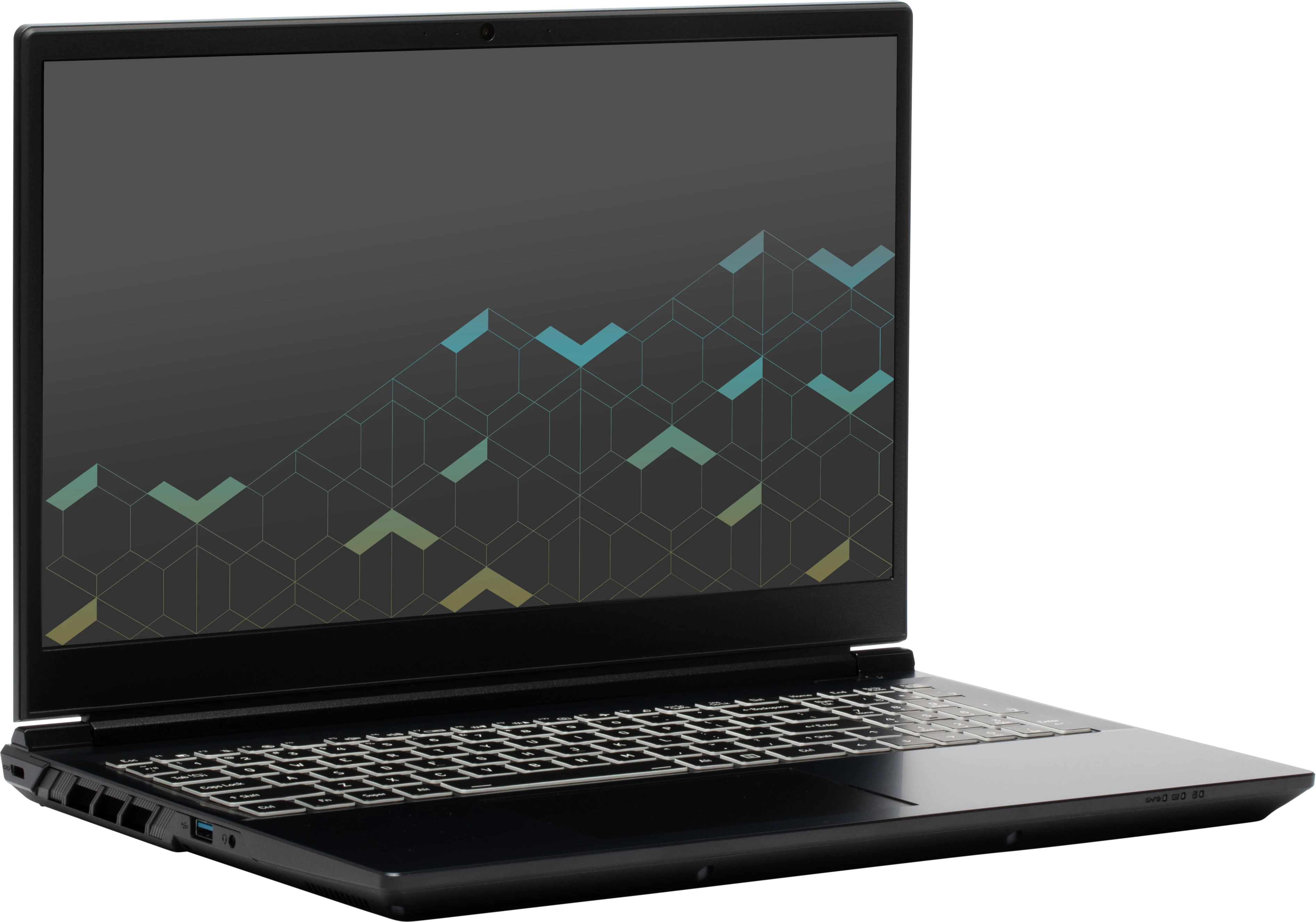
The System76 Adder WS is a laptop with the following specifications:
- CPU
- Supports Intel Core Ultra 2nd generation (Arrow Lake) CPUs
- Chipset
- BIOS
- Puya PY25F256LC4L1TS1A flash chip (or equivalent)
- WSON-8 form factor
- Programmed with System76 firmware (non-open)
- Puya PY25F256LC4L1TS1A flash chip (or equivalent)
- EC
- ITE IT5570E
- Programmed with non-open EC firmware
- Graphics
- GPU options:
- 15" model:
- NVIDIA GeForce RTX 5060
- NVIDIA GeForce RTX 5050
- 17" model:
- NVIDIA GeForce RTX 5070
- NVIDIA GeForce RTX 5060
- 15" model:
- eDP display options:
- 15.6" 1920x1080@144Hz LCD
- LCD panel: Innolux N156HMA-GA1 (or equivalent)
- Brightness: 250 nits (cd/m²)
- Color coverage:
- DCI-P3: 74%
- sRGB: 100%
- sRGB color coverage: 100
- LCD panel: Innolux N156HMA-GA1 (or equivalent)
- 17.3" 1920x1080@144Hz LCD
- LCD panel: Innolux N173HCE-G33 (or equivalent)
- Brightness: 300 nits (cd/m²)
- Color coverage:
- DCI-P3: 74%
- sRGB: 100%
- LCD panel: Innolux N173HCE-G33 (or equivalent)
- 15.6" 1920x1080@144Hz LCD
- External video outputs:
- 1x HDMI 2.1
- 2x DisplayPort 2.1 over USB-C
- GPU options:
- Memory
- Up to 96GB (2x48GB) dual-channel DDR5 SO-DIMMs @ 5600 MHz
- Networking
- 2.5-Gigabit Ethernet
- M.2 PCIe/CNVi WiFi/Bluetooth:
- Intel Wi-Fi 7 BE200
- Bluetooth 5.4
- Intel Wi-Fi 7 BE200
- Power
- 230W (20V, 11.5A) DC-in port
- Barrel size: 5.5mm (outer), 2.5mm (inner)
- 73Wh 4-cell Lithium-Ion battery
- 230W (20V, 11.5A) DC-in port
- Sound
- Internal speakers & microphone
- Combined headphone & microphone 3.5mm jack
- HDMI, USB-C DisplayPort audio
- Storage
- 3x M.2 PCIe NVMe Gen 4
- USB
- 2x USB 3.2 Gen 2 Type-C
- Both ports support DisplayPort over USB-C
- Right-side port supports USB-C charging (USB-PD)
- 1x USB 3.2 Gen 2 Type-A
- 1x USB 3.2 Gen 1 Type-A
- 2x USB 3.2 Gen 2 Type-C
- Dimensions
- 15" model: 36.1cm x 24.85cm x 2.89cm, 2.4kg
- 17" model: 39.7cm x 26.51cm x 2.86cm, 2.8kg
Adder WS (External Overview)
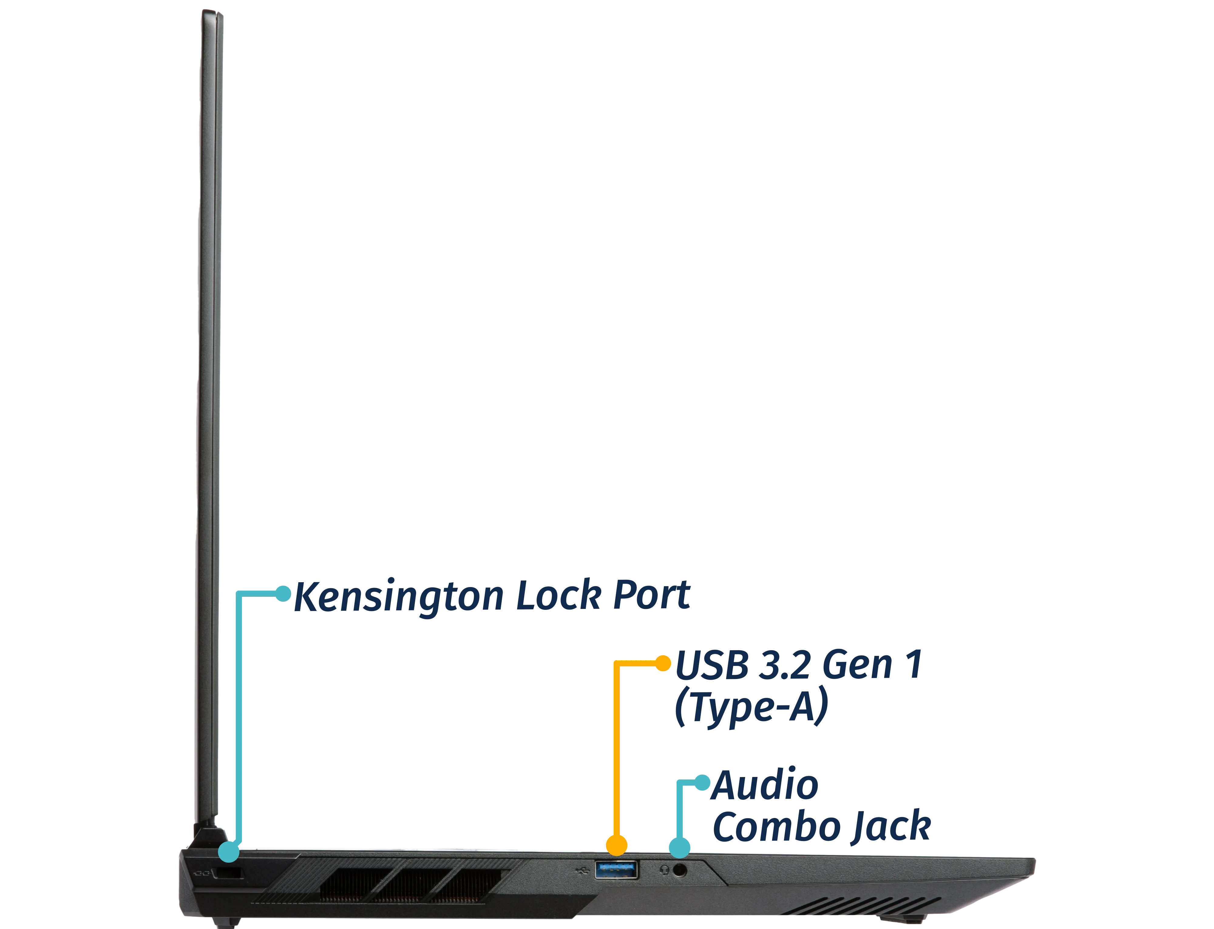
Left side:
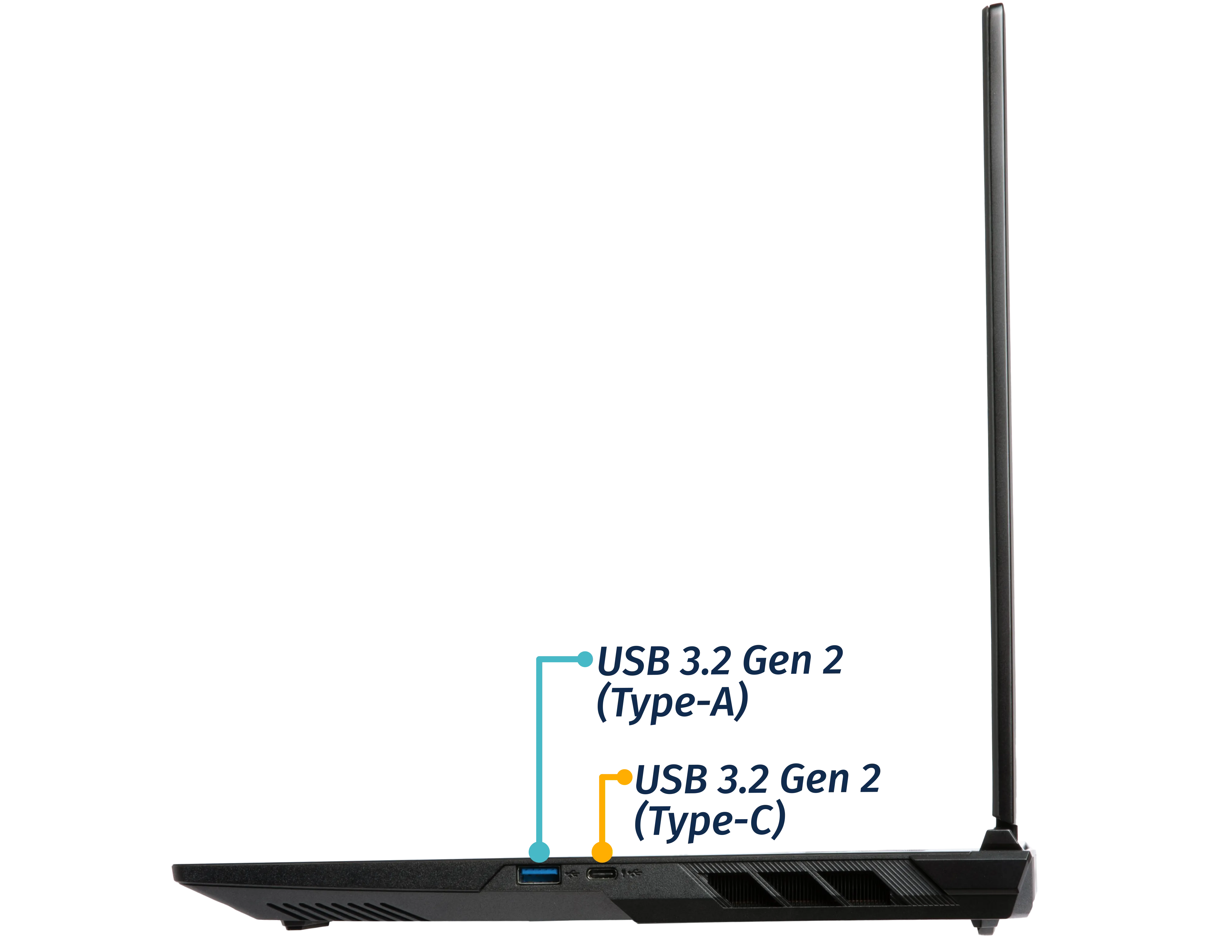
Right side:
Front side:

Back side:

Keyboard & touchpad:
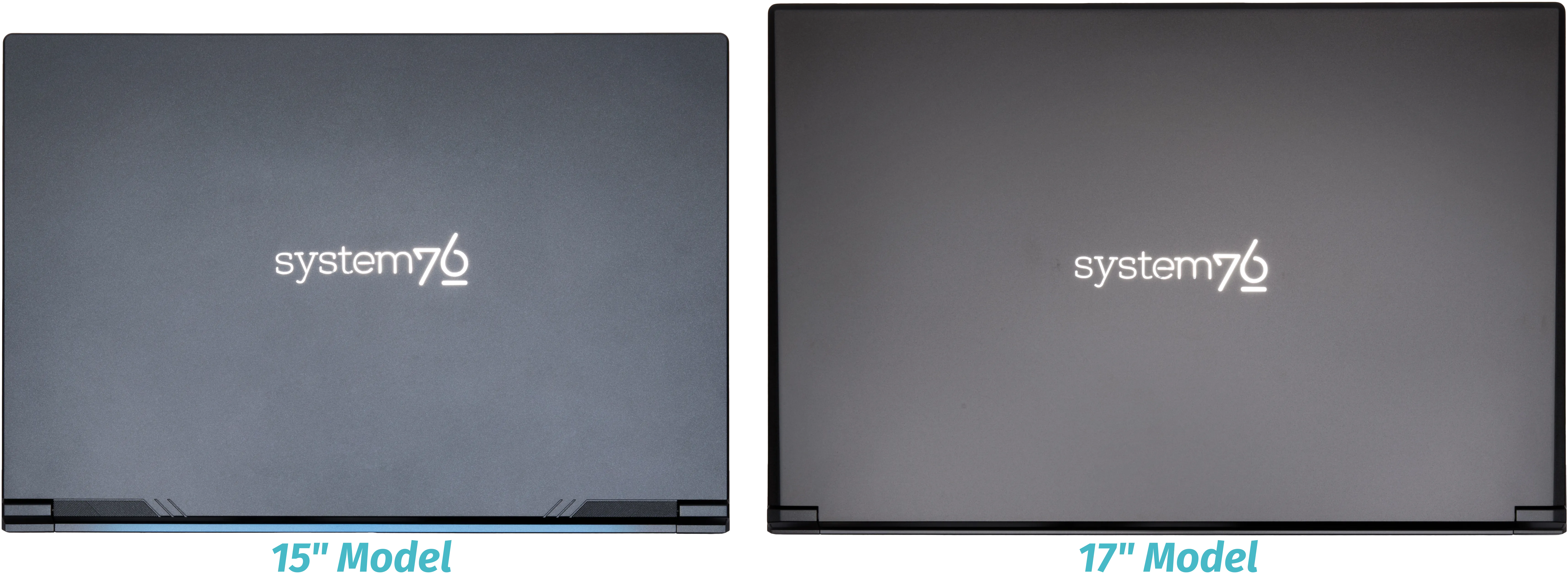
15" model:

Lid:
Materials:
15" model:
| Part | Material | Part Number |
|---|---|---|
| LCD back cover (lid) | Plastic | 6-39-V3501-022 |
| LCD front cover (bezel) | Plastic | 6-39-V3501-012 |
| Top case (palm rests/port covers) | Plastic | 6-39-V3502-012 |
| Bottom panel | Plastic | 6-39-V35W3-011 |
17" model:
| Part | Material | Part Number |
|---|---|---|
| LCD back cover (lid) | Aluminum | 6-39-V37S1-022 |
| LCD front cover (bezel) | Plastic | 6-39-V37S1-012 |
| Top case (palm rests/port covers) | Plastic | 6-39-V37S2-N11 |
| Bottom panel | Plastic | 6-39-V37W3-011 |
LED indicators
The Adder WS has the following LED indicators:
| Icon | Color | Description |
|---|---|---|
 | Orange | Powered off, DC power plugged in |
| Green | Powered on | |
| Blinking green | Sleeping (suspended) | |
 | Orange | Battery charging |
| Green | Battery fully charged | |
| Blinking orange | Battery critically low | |
 | Green | Storage drive activity |
Keyboard Shortcuts
The Adder WS has the following actions available using the Fn and Function keys:
| Key | Shortcut | Action |
|---|---|---|
 | Fn+F1 | Toggle trackpad |
 | Fn+F2 | Mute/unmute microphone |
 | Fn+F3 | Mute/unmute speakers |
 | Fn+F5 | Volume down |
 | Fn+F6 | Volume up |
 | Fn+F7 | Toggle displays |
 | Fn+F8 | Screen brightness down |
 | Fn+F9 | Screen brightness up |
 | Fn+F10 | Toggle webcam |
 | Fn+F11 | Toggle airplane mode |
 | Fn+F12 | Suspend |
 | Fn+` | Play/Pause |
 | Fn+* | Toggle keyboard backlight |
 | Fn+/ | Cycle keyboard color |
 | Fn+- | Decrease keyboard brightness |
 | Fn++ | Increase keyboard brightness |
| 1 | Fn+1 | Toggle fan between max/automatic |
Adder WS (Internal Overview)
Bottom components and connectors:
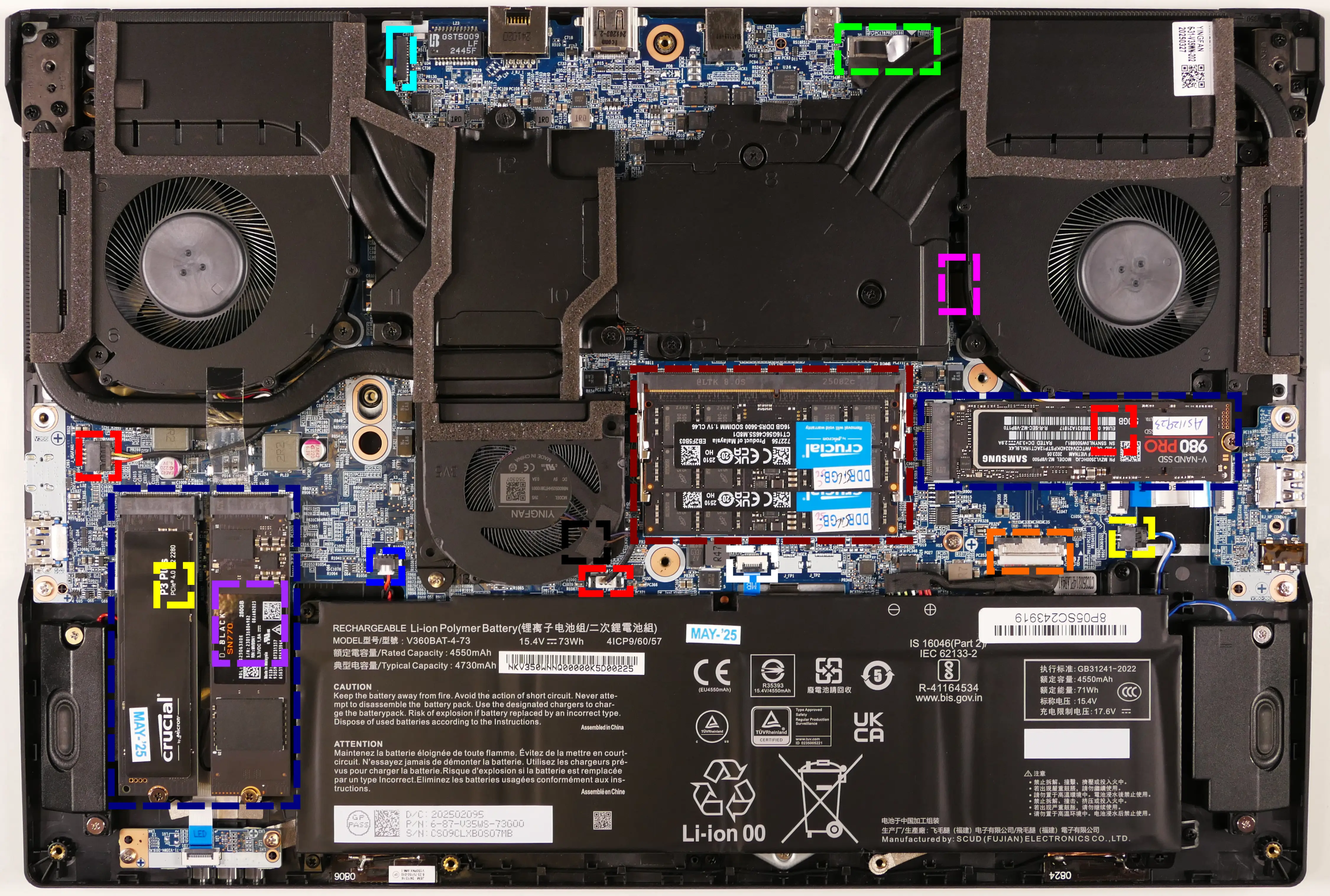
- LCD panel connector is highlighted in light green
- LCD panel connector is partially below the heatsink
- Keyboard adhesive access point is highlighted in pink
- RAM slots are highlighted in maroon
- M.2 SSDs are highlighted in navy
- All slots support PCIe NVMe Gen 4
- Fan connectors are highlighted in red
- Left fan connector (on the right) is below SSD slot #3
- Speaker connectors are highlighted in yellow
- Right speaker connector (on the left) is below SSD slot #2
- Webcam/microphone connector is highlighted in cyan
- Wireless card is highlighted in purple
- Wireless card is below SSD slot #1
- CMOS battery connector is highlighted in blue
- CMOS battery is below the main battery
- Touchpad connector is highlighted in white
- Main battery connector is highlighted in orange
- BIOS flash chip (U62) is highlighted in black
- BIOS chip is below the middle fan
Under-keyboard components and connectors:
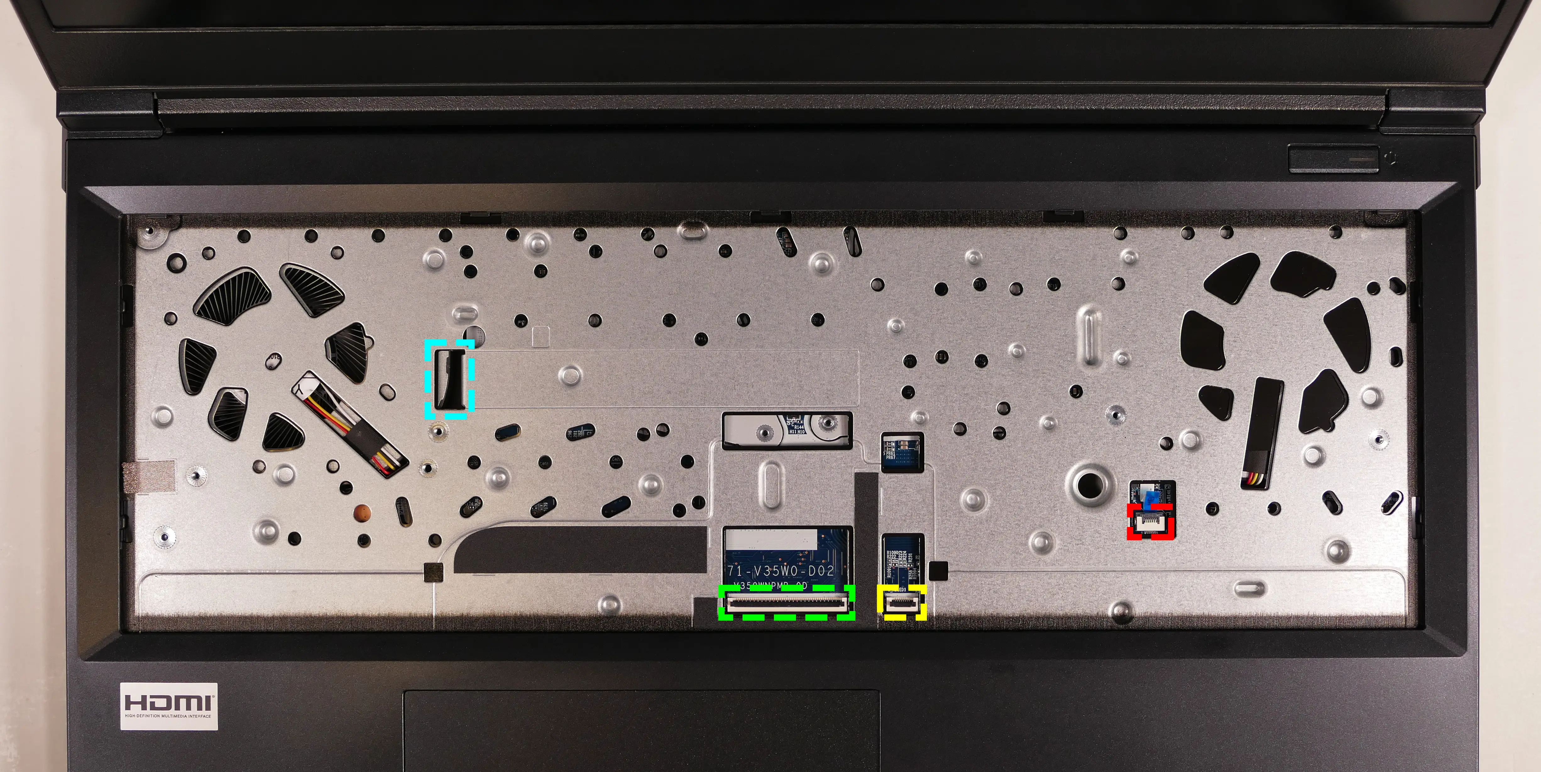
- Keyboard adhesive strip access point is highlighted in cyan
- Keyboard connector is highlighted in green
- Keyboard backlight connector is highlighted in yellow
- Power button/LED connector is highlighted in red
Adder WS (Parts & Repairs)
Many components in your Adder WS can be upgraded or replaced as necessary.
This page contains photos and part numbers for both the 15" model and the 17" model of the Adder WS 5 (addw5). Unless otherwise noted, photos are of the 15" model, and general component locations are the same between both models.
Follow these step-by-step guides for instructions:
- Removing the bottom cover
- Replacing the RAM
- Replacing an M.2/NVMe SSD
- Replacing the battery
- Replacing the CMOS battery
- Replacing the WiFi/Bluetooth module
- Replacing the fans/heatsink/thermal paste
- Replacing the keyboard
- Replacing the speakers
Removing the bottom cover:
Removing the cover is required to access the internal components. Prior to removing the cover, ensure the AC power is unplugged and all peripherals (such as USB drives) are unplugged or removed from the system.
Part numbers:
- Bottom panel:
- 15" model:
6-39-V35W3-011 - 17" model:
6-39-V37W3-011
- 15" model:
Tools required: Cross-head (Phillips) screwdriver
Time estimate: 5 minutes
Difficulty: Easy ●
Steps to remove the bottom cover:
- Place the machine lid-side down.
- Use a soft surface (such as a towel) to avoid scratches.
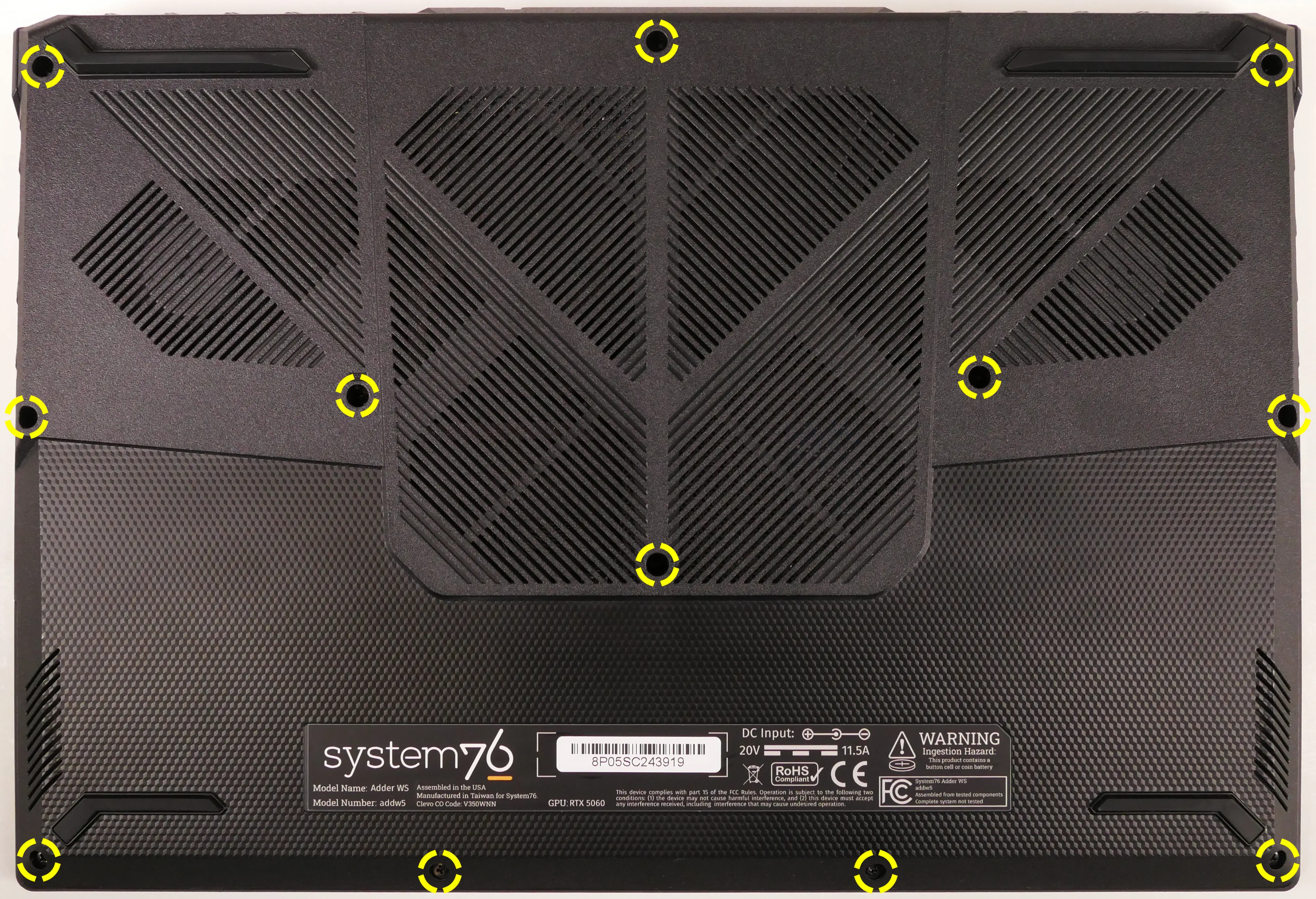
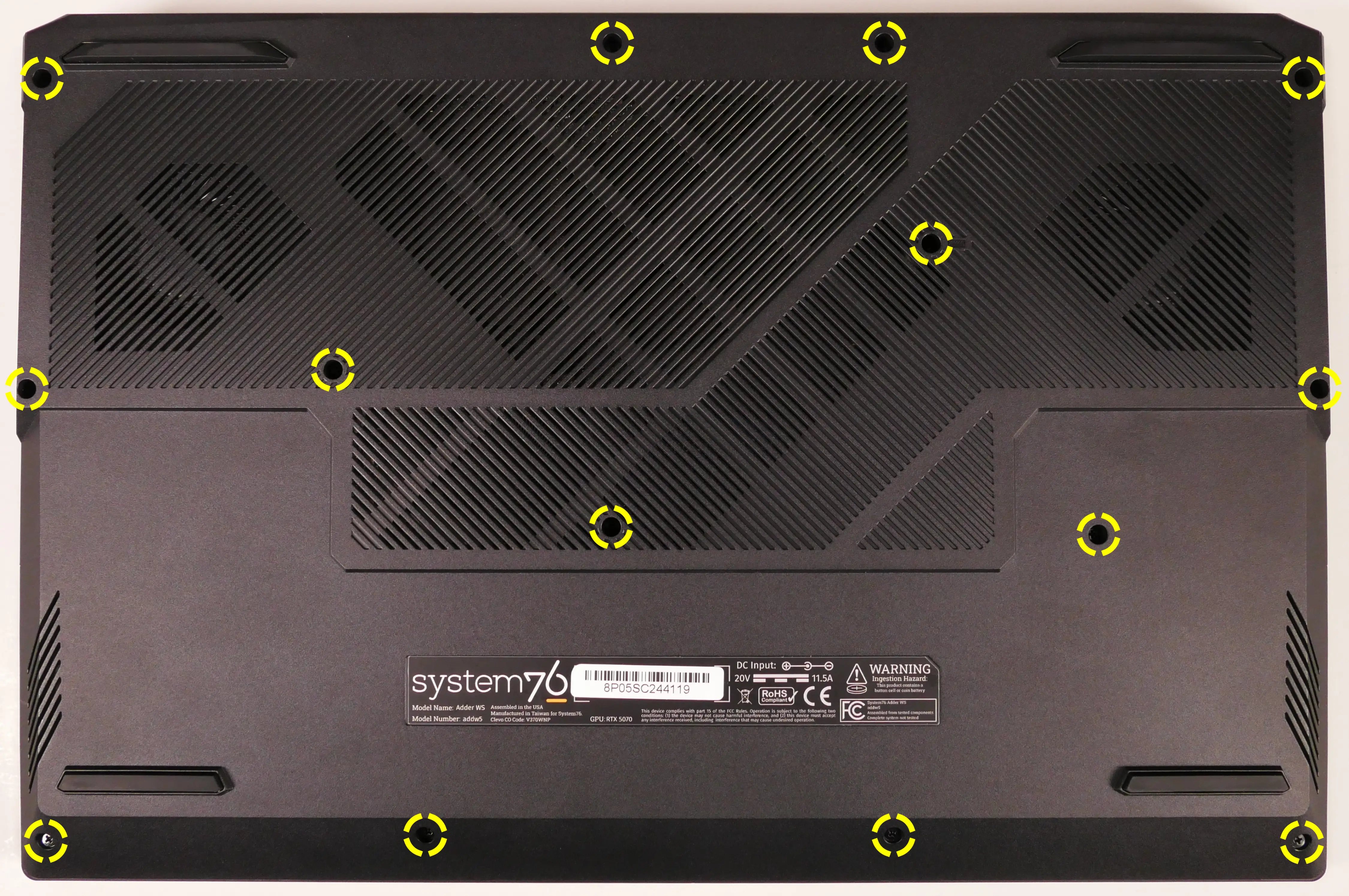
- Remove the bottom panel screws.
- The 15" model (top) has 12 bottom panel screws.
- The 17" model (bottom) has 14 bottom panel screws.
- Pull the bottom panel off, starting from the hinges in the back.
Replacing the RAM:
The Adder WS 5 supports up to 96GB (2x48GB) of DDR5 SO-DIMMs running at 5600MHz. If you've purchased new RAM, need to replace your RAM, or are reseating your RAM, follow these steps.
Tools required: Cross-head (Phillips) screwdriver
Time estimate: 10 minutes
Difficulty: Easy ●
Steps to replace the RAM:
- Follow the steps above to remove the bottom cover.
- Press the small tabs on both sides of the RAM simultaneously. The RAM should spring up to an angle.
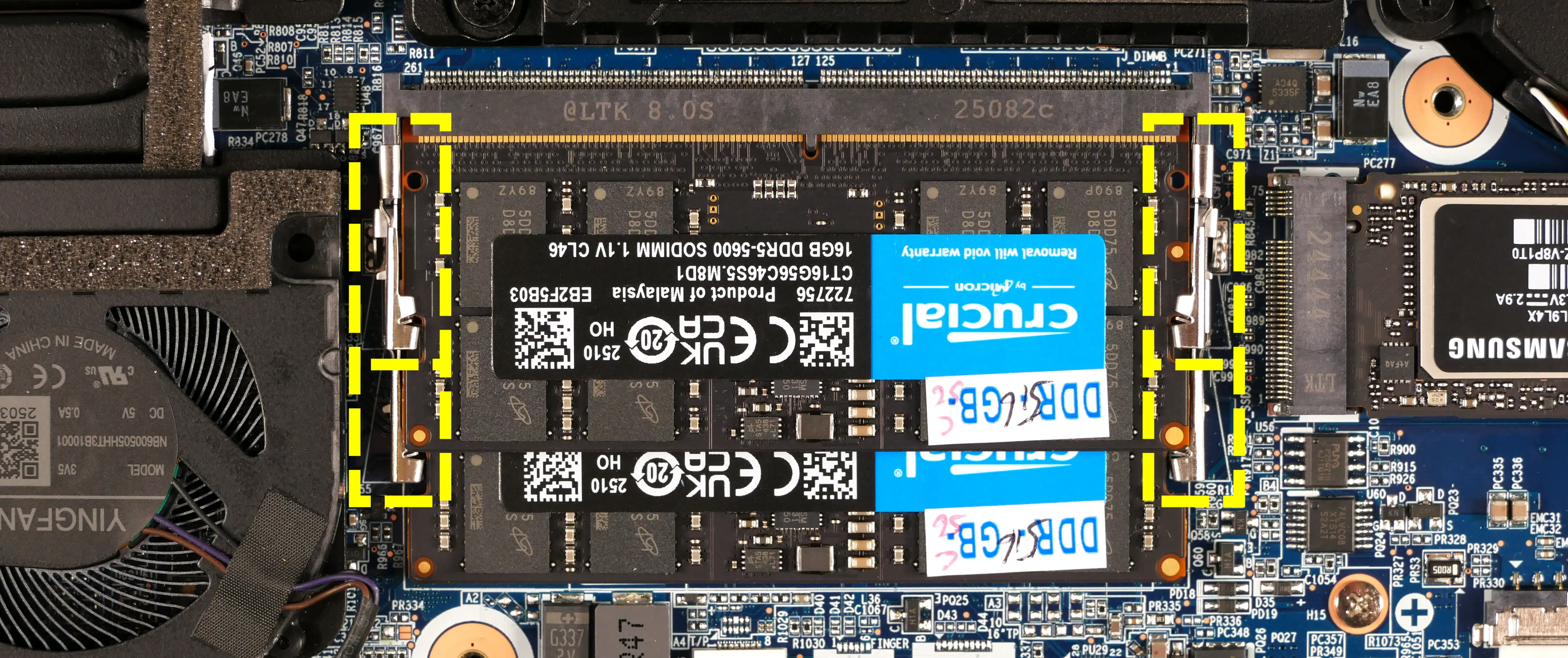
- Remove the RAM from the slot.
- Insert the new RAM (or reseat the existing RAM) by placing it in the keyed slot and pressing down on the RAM until it clicks into place.
Replacing an M.2/NVMe SSD:
This model supports up to three M.2 SSDs. All M.2 slots are size 2280 and support PCIe NVMe Generation 4.
Tools required: Cross-head (Phillips) screwdriver
Time estimate: 10 minutes
Difficulty: Easy ●
Steps to replace the M.2 drive:
- Follow the steps above to remove the bottom cover.
- Unscrew the retainer screw opposite the M.2 slot.
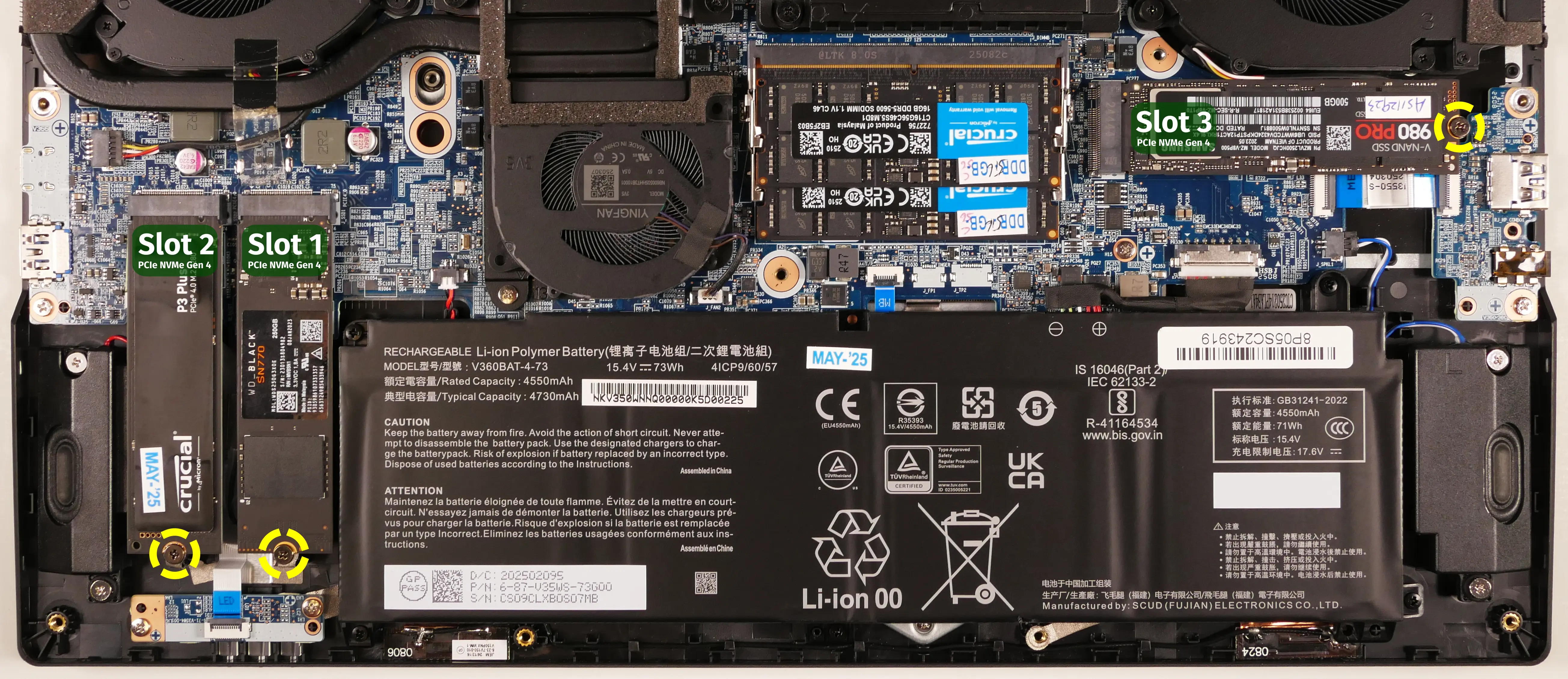
- Remove the existing M.2 drive by pulling it out of the slot.
- Insert the new M.2 drive into the slot and hold it in place.
- Replace the retainer screw.
Replacing the battery:
The battery provides primary power whenever the system is unplugged.
Part numbers:
- The battery's model number is
V360BAT-4-73, and the original part number is6-87-V35WS-73G00.- Third-party battery sellers may list one or both of these numbers, and may offer other compatible part numbers with the same model number.
- You can also contact System76 to purchase a replacement battery.
Tools required: Cross-head (Phillips) screwdriver
Time estimate: 10 minutes
Difficulty: Easy ●
Steps to replace the battery:
- Follow the steps above to remove the bottom cover.
- Remove the battery screws.
- The 17" model has four battery screws (one at each corner).
- The 15" model has a fifth battery screw (in the bottom center).

- Unplug the white connector connecting the battery to the motherboard.
- Remove and replace the battery.
- When plugging in the new battery, the red wire on the connector goes on the left, and the black wire goes on the right.
Replacing the CMOS battery:
The CMOS battery supplies power to the system's CMOS chip. UEFI settings and the computer's hardware clock are stored on the CMOS. If your system doesn't boot, you can reset the CMOS to force a low-level hardware reset. If your clock is constantly resetting, it's likely your CMOS battery needs to be replaced.
Warning (ingestion hazard): Keep batteries out of reach of children. Death or serious injury can occur if ingested. If a battery is suspected to be swallowed or inserted inside any part of the body, seek immediate medical attention. In the US, you can also call the National Battery Ingestion Hotline for guidance: +1 (800) 498-8666
Part numbers:
- The CMOS battery is a standard 3V KTS CR2032W battery.
Tools required: Cross-head (Phillips) screwdriver
Time estimate: 15 minutes
Difficulty: Medium ●
Steps to replace the CMOS battery:
- Follow the steps above to remove the bottom cover and remove the main battery.
- If you are not replacing the CMOS battery, then removing the main battery is optional.
- Unplug the small white connector that connects the CMOS battery to the motherboard. If you are replacing the battery, gently pull from the sides to pry it up from where it's stuck to the case.
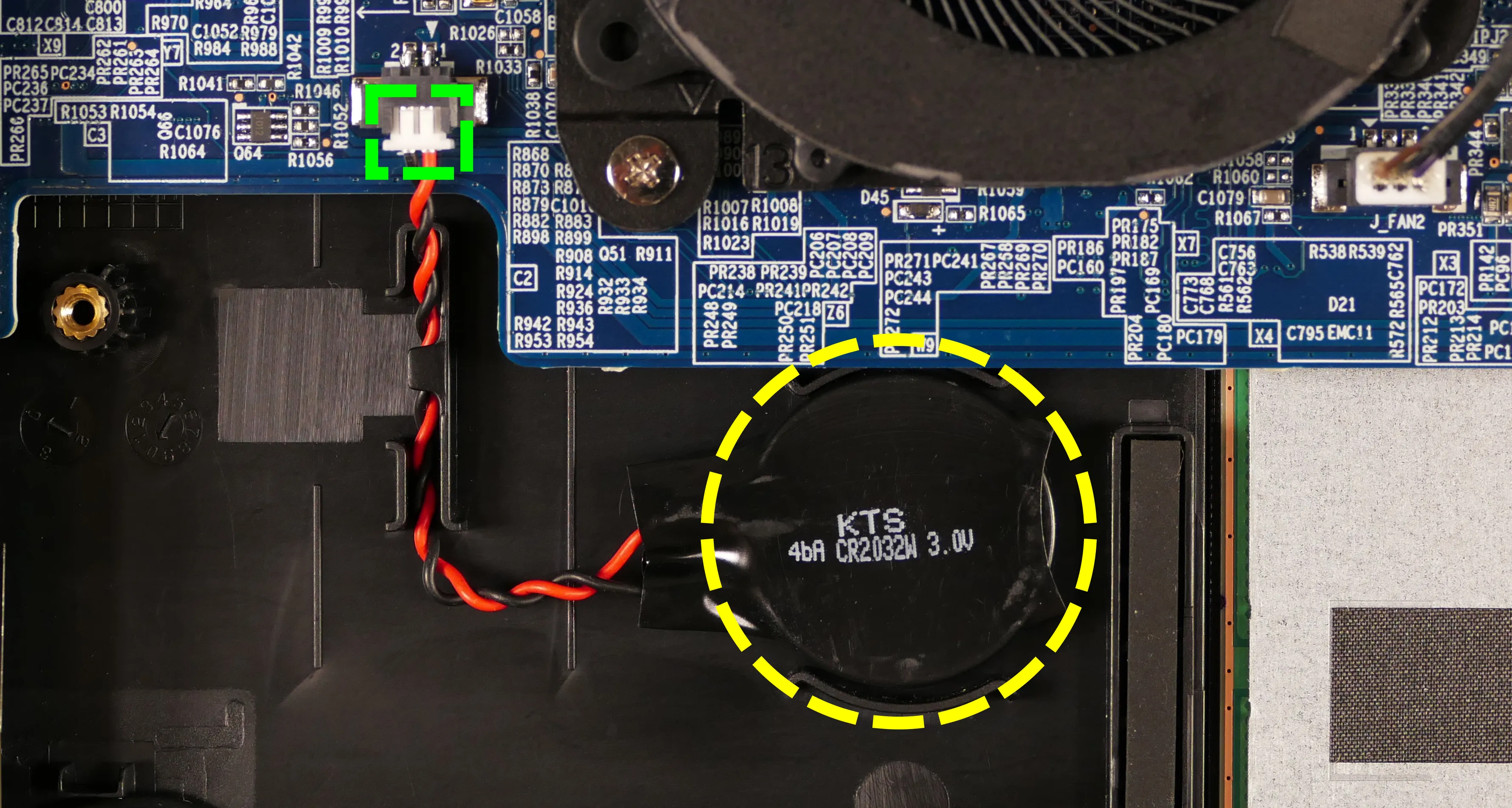
- To clear the CMOS, disconnect the main battery (if it's still installed), open the lid of the machine, and hold down the power button for at least 15 seconds to discharge any residual energy in the system.
- Reconnect the CMOS battery and reinstall the main battery.
- Replace the bottom panel and power up the Adder WS. The system may power itself off and on after initial boot; this is normal behavior when the CMOS has been reset.
Replacing the wireless card:
Your Adder WS's WiFi and Bluetooth are both handled by the same module. It is a standard M.2 2230 slot with PCIe and USB interfaces (E-key).
Part number:
- The standard wireless card is an Intel
BE200.
Tools required: Cross-head (Phillips) screwdriver
Time estimate: 10 minutes
Difficulty: Medium ●
Steps to replace the WiFi/Bluetooth module:
- Follow the steps above to remove the bottom cover and remove the SSD from slot 1 (the innermost slot), if installed.
- You can optionally remove the SSD from slot 2 for easier access.
- Locate the wireless card. Remove any black tape covering the card.
- Unscrew the wireless card screw holding the card and its wire bracket in place.
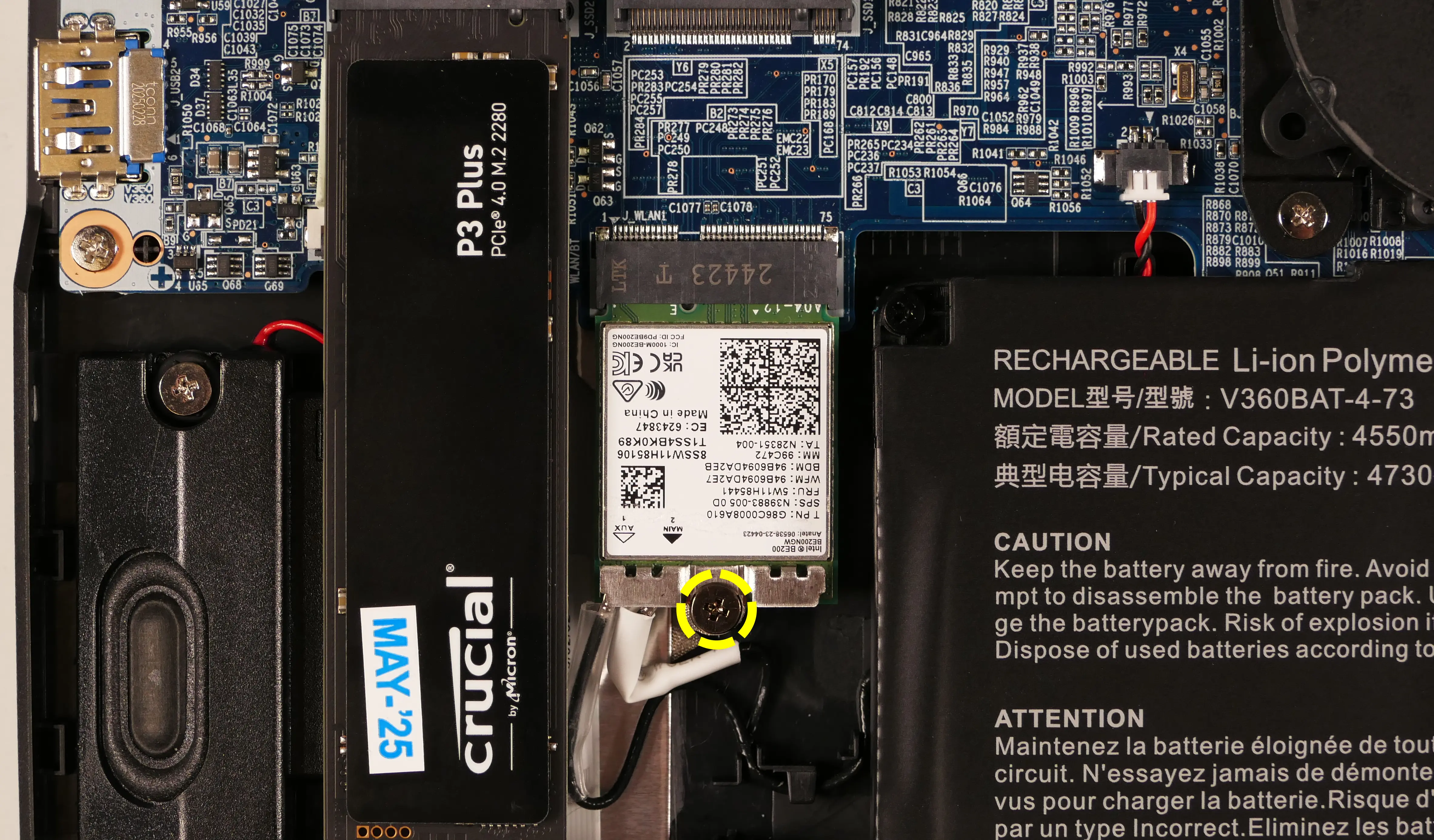
- Remove the metal bracket that holds the wires onto the card.
- Gently remove the two antennas (highlighted red below) by pulling them up and away from the wireless card.
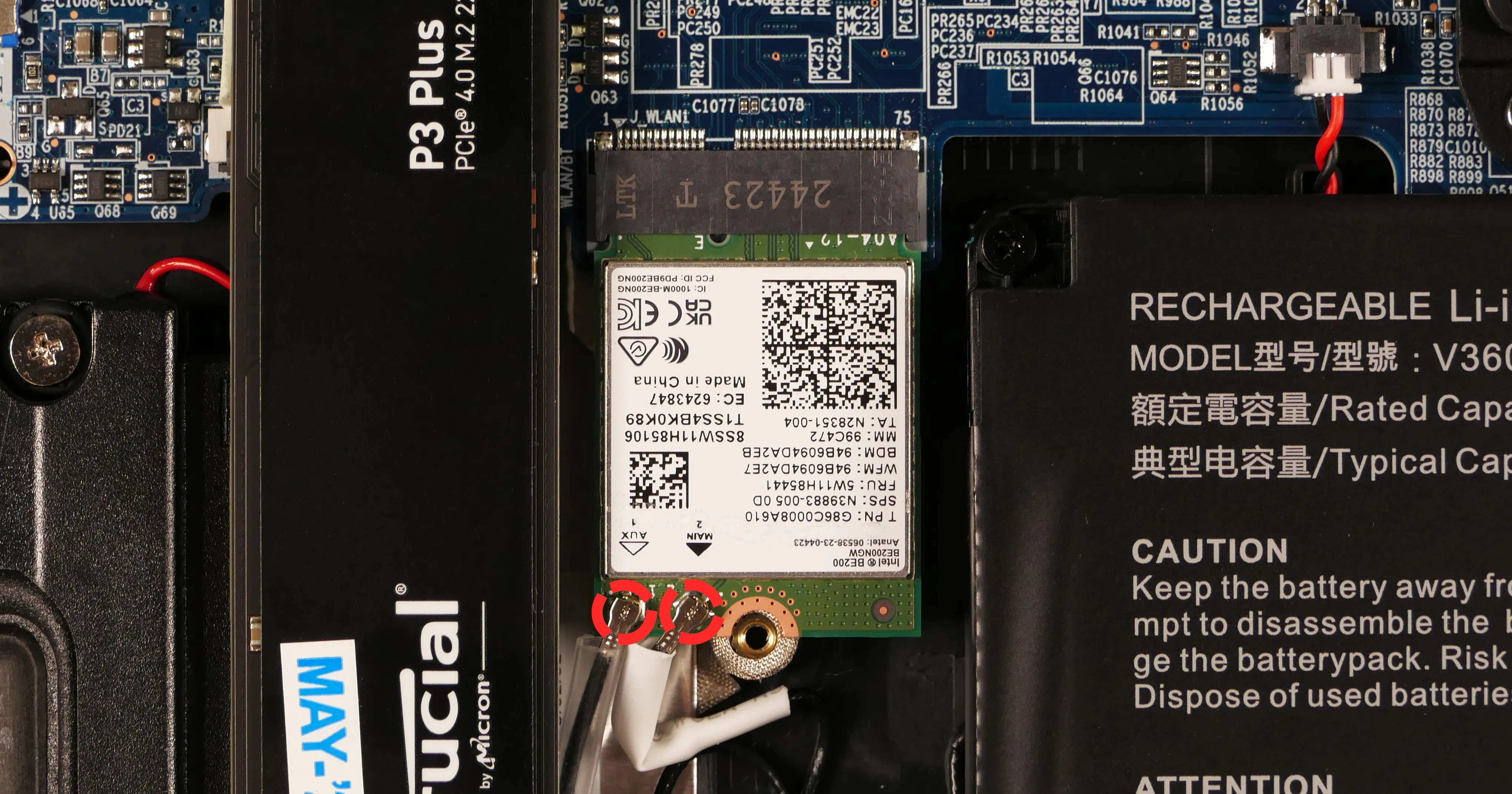
- Keeping the wireless card parallel with the motherboard, slide the card out of the M.2 slot.
- Insert the new wireless card into the M.2 slot.
- Attach the two antennas by aligning the circular fittings and pressing onto the wireless card. The connectors will snap into place. Use caution when attaching the connectors; the pins can bend, break, or snap.
- Replace the metal bracket and the retaining screw.
- Replace the M.2 SSD in slot 1 (if necessary) and bottom panel.
Replacing the cooling system:
The Adder WS 5 has a single heatsink assembly with three fans. This assembly cools the CPU and GPU.
If the fans become noisy and cleaning them out doesn't fix the issue, you may need a new fan. Contact support to start a warranty claim or parts purchase. These instructions can also be used if physical damage to the heatsink necessitates its replacement.
Thermal paste helps facilitate effective heat transfer between the CPU/GPU and the cooling equipment; depending on your climate and the age of the machine, replacing the thermal paste may improve cooling performance. The thermal paste should generally be replaced whenever the heatsink is removed.
Thermal putty (thicker than thermal paste) is used to bridge the gap between the VRAM chips and the heatsink. Replacing the thermal putty is optional when removing the heatsink. System76 suggests Thermal Grizzly Putty Basic (available at various retailers) or a similar alternative.
Part numbers:
- Fan/heatsink assembly:
- 15": Yingfan
6-31-V35WN-202 - 17": Yingfan
6-31-V37WN-202
- 15": Yingfan
- Left fan: Yingfan
5V6 - Middle/bottom fan: Yingfan
3V5 - Right fan: Yingfan
5V7
Tools required: Cross-head (Phillips) screwdriver, thermal putty spreader (flat plastic tool)
Time estimate: 25 minutes
Difficulty: High ●
Steps to replace the heatsink/thermal paste:
- Follow the steps above to remove the bottom cover and remove the SSD from slot 3 (if installed).
- Remove any clear tape that is securing the fan wires.
- Remove the thirteen heatsink and fan screws in order of the stamped numbers, starting with #1, then #2, and continuing until you have removed #13.
- The black screws (#1-#12) are held captive, and will not completely detatch from the heatsink/fans. The silver screw (#13) is not held captive, and will come loose when untightened.
- Do not remove the smaller black screws holding the fan covers onto the fans.
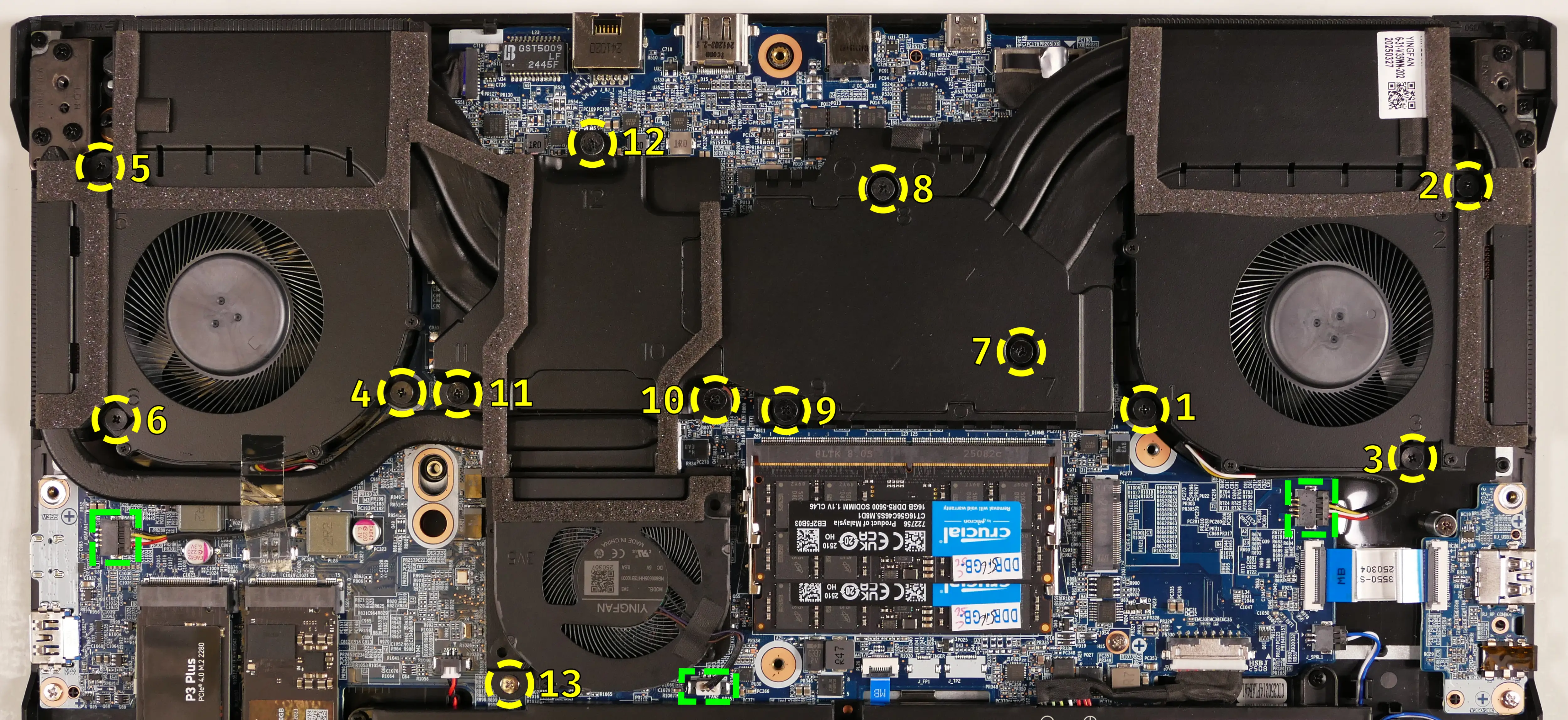
- Unplug the three fan connectors from the motherboard (highlighted green above).
- Remove the heatsink/fans from the case, being careful not to bend the heatsink pipes. It may take some pressure to break the seal of the thermal paste.
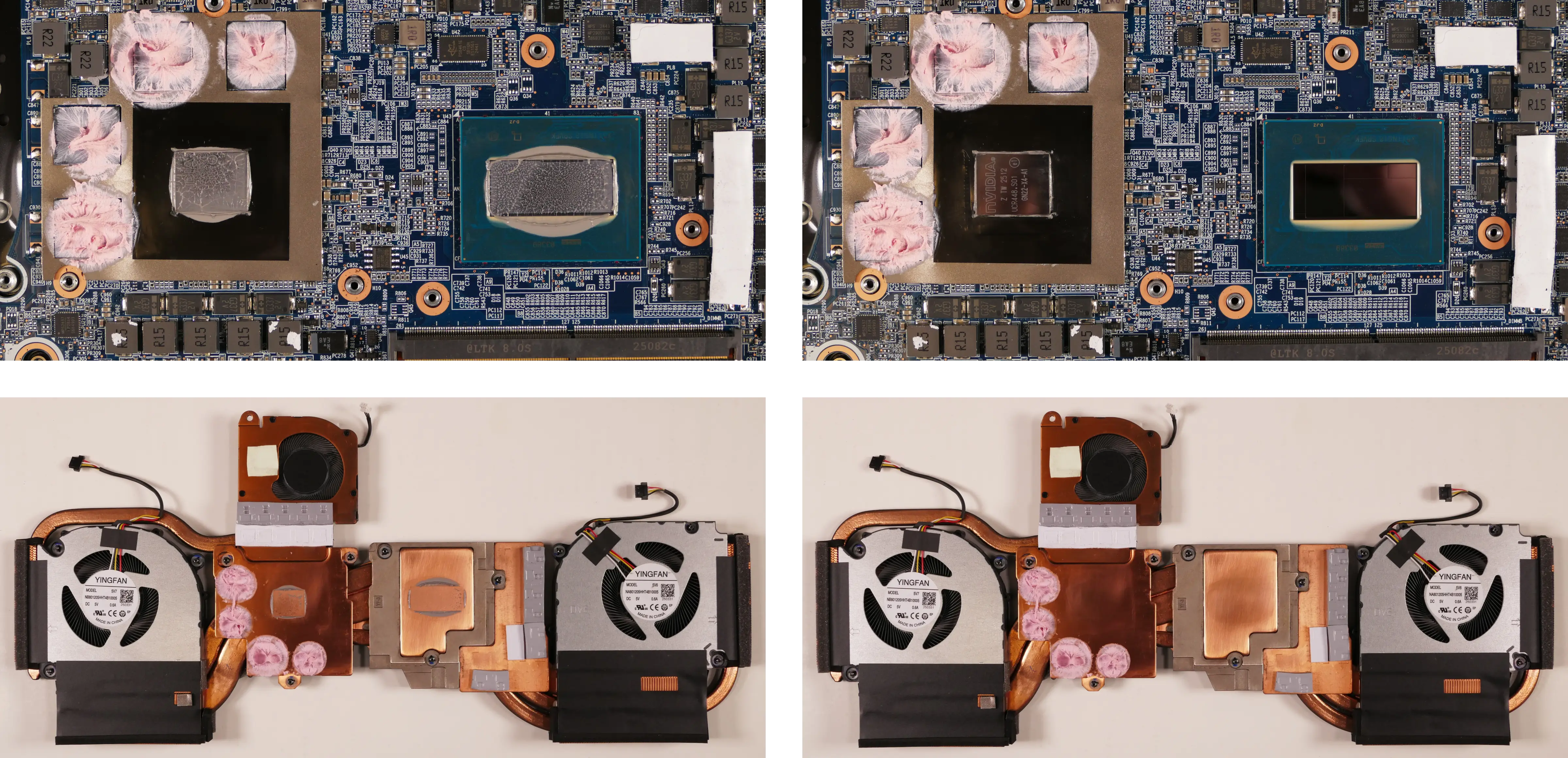
- Using a paper towel, remove the existing thermal paste from the CPU, GPU, and heatsink. You may also use a small amount of rubbing alcohol if the old paste is dried or difficult to remove.
- You can optionally remove the thermal putty from the four VRAM chips surrounding the GPU chip if you have replacement thermal putty to install.
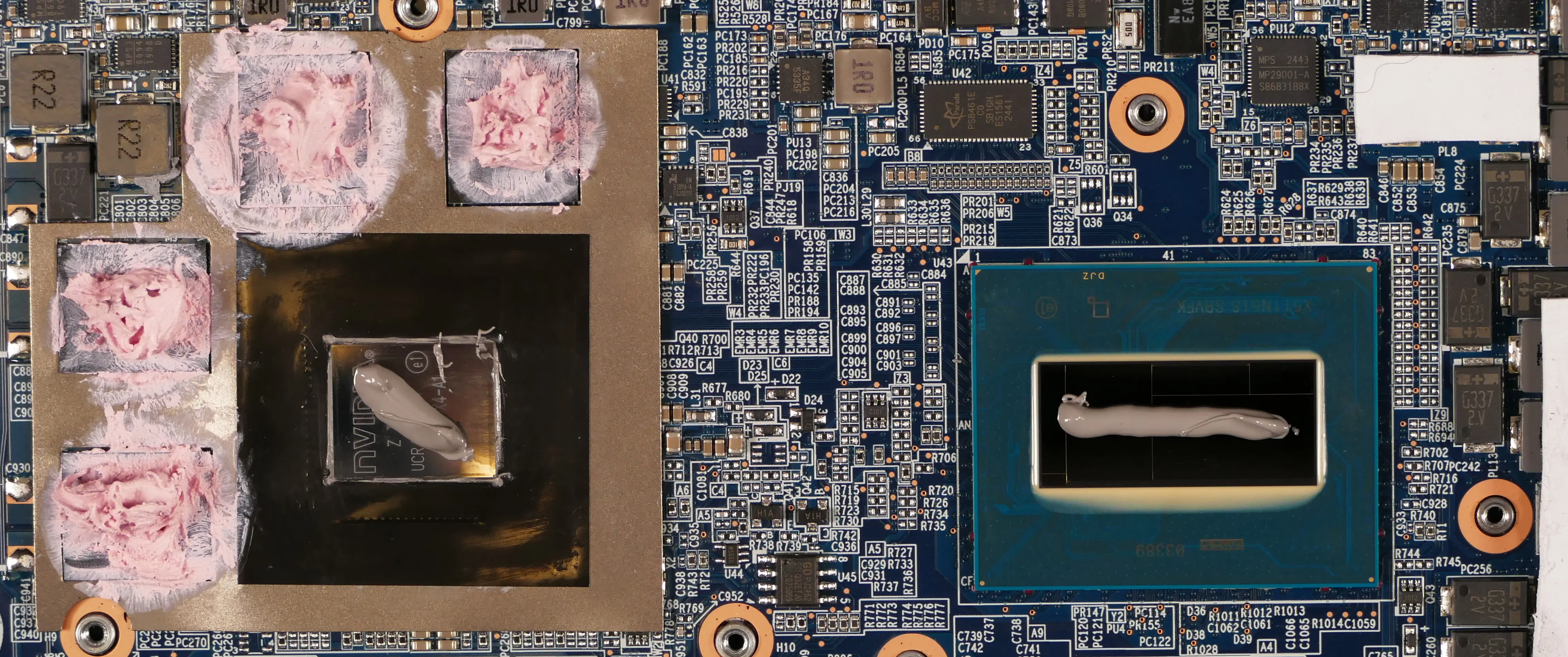
- Apply a small line of thermal paste directly onto the CPU chip and the GPU chip.
- If you're also replacing the thermal putty, apply the new putty to the four VRAM chips.
- If you aren't replacing the thermal putty, scoop the existing putty (from the VRAM chip and the corresponding location on the heatsink) into the center of each VRAM chip using a flat plastic tool.
- Carefully replace the heatsink.
- Replace the fan and heatsink screws, starting with #1, then #2, and so on until #13.
- Plug the two white fan connectors back into the motherboard.
Replacing the keyboard:
The keyboard can be replaced if its switches or electronics have been damaged.
Warning: The keyboard is held in by a strip of adhesive in addition to one of the bottom panel screws and the perimeter clips. The adhesive may be difficult to remove from the keyboard and/or case, and while the keyboard should still be functional if removed carefully, it is possible that permanent aesthetic damage will occur to the bottom side of the keyboard during removal. Removal is not recommended unless the keyboard is malfunctioning.
Part numbers:
- The keyboard's model number is
CVM22K33US943001, and its part number is6-80-PE610-01A-1M1, also known as6-V355SNP-KB-MCL-US.- Keyboards shipped by System76 include a custom-printed Super key.
Tools required: Cross-head (Phillips) screwdriver, tweezers, spudger tool (optional)
Time estimate: 20 minutes
Difficulty: Hard ●
Steps to replace the keyboard:
- Follow the steps above to remove the bottom cover.
- Pull the keyboard adhesive out of the machine to detatch it from the keyboard.
- The adhesive strip access point is highlighted green below (top: 15"; bottom: 17").
- On the 15" model, if the end of the keyboard adhesive strip is tucked behind the fan, it can be pulled out using tweezers or a small screwdriver, or the thermal system can be removed to expose it.
- Replacing the thermal paste is recommended if the thermal system is removed.
- Pull the adhesive strip slowly to avoid breaking it. Grasp farther down the strip as it comes out of the machine (don't pull the end far away from the machine.)
- If the adhesive strip breaks, remove as much of it as possible. The keyboard can be reinstalled without the adhesive strip.
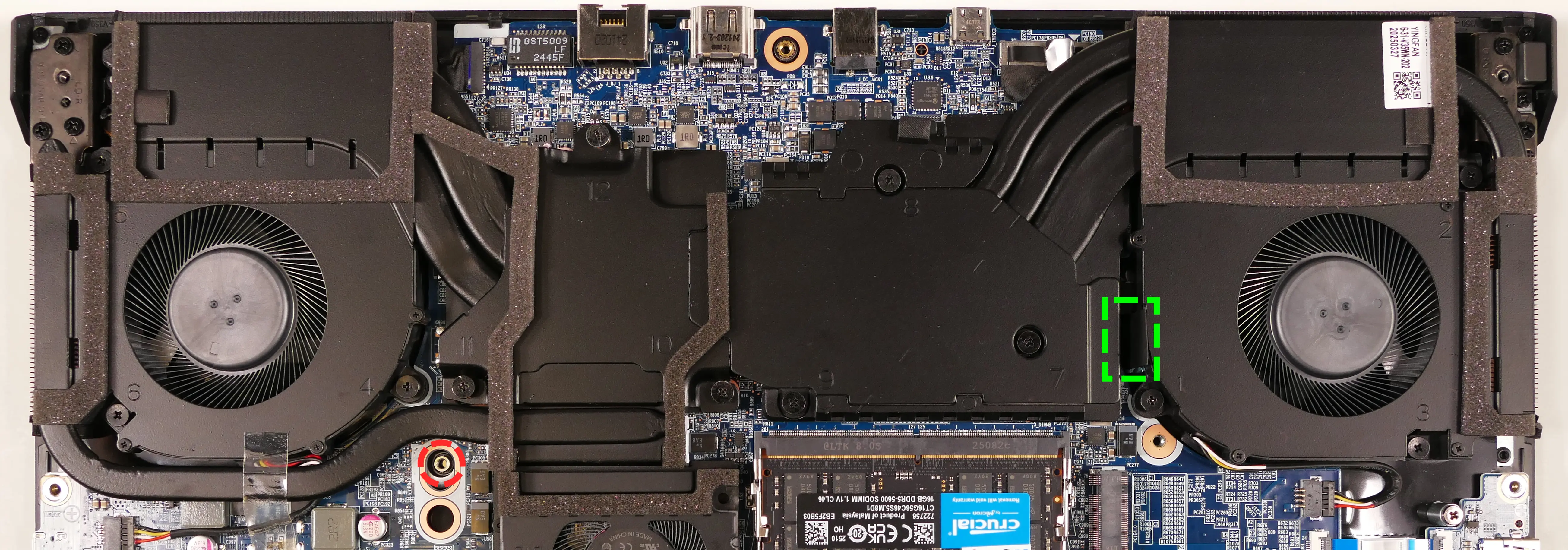

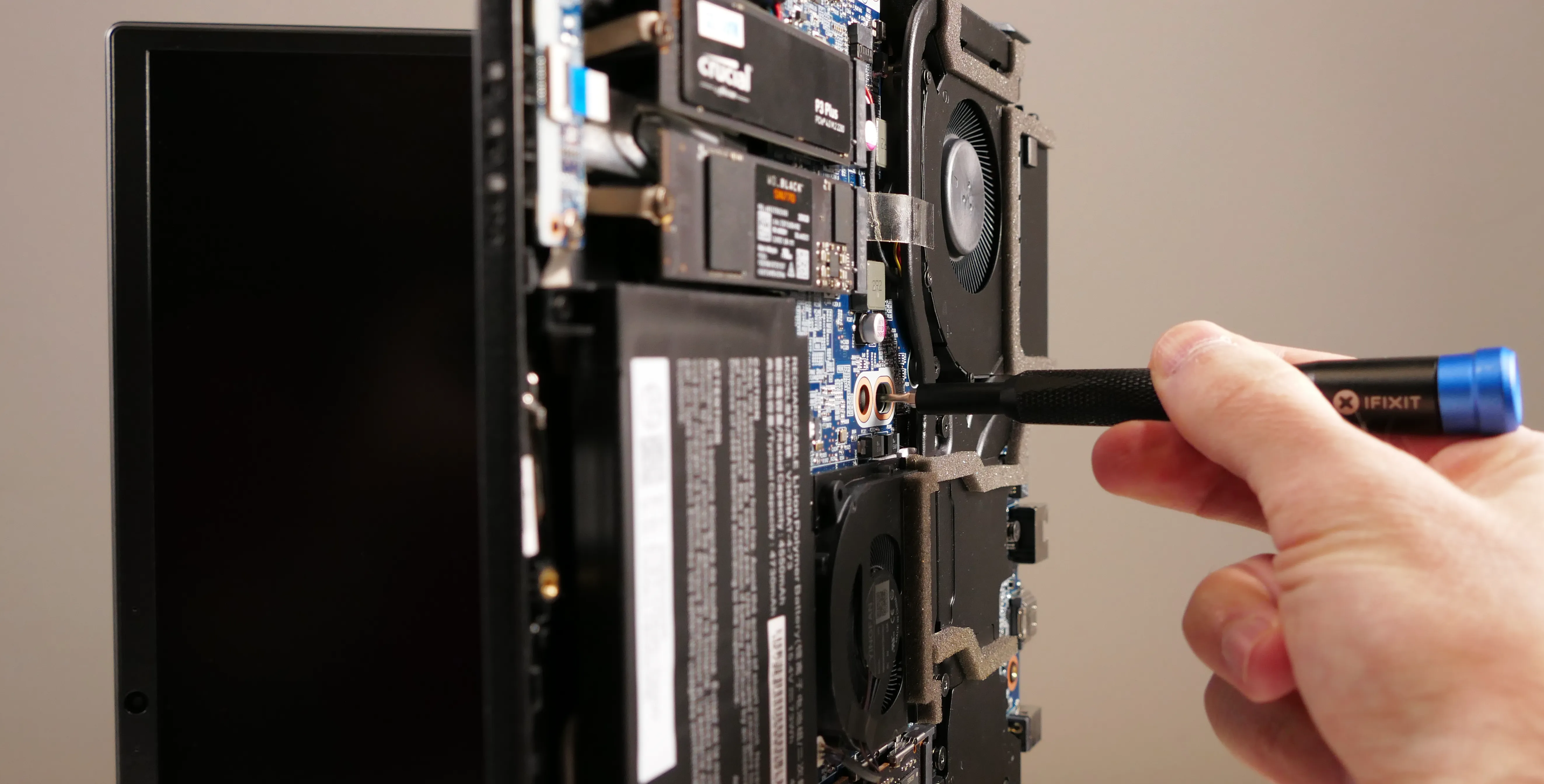
- Open the lid slightly and place the machine on its side.
- Push the screwdriver into the keyboard push point (highlighted red above) until the keyboard pops out.
- Set the machine back down and raise the keyboard away from the chassis. The larger ribbon cable is for the keyboard, while the smaller ribbon cable is for the keyboard backlight.
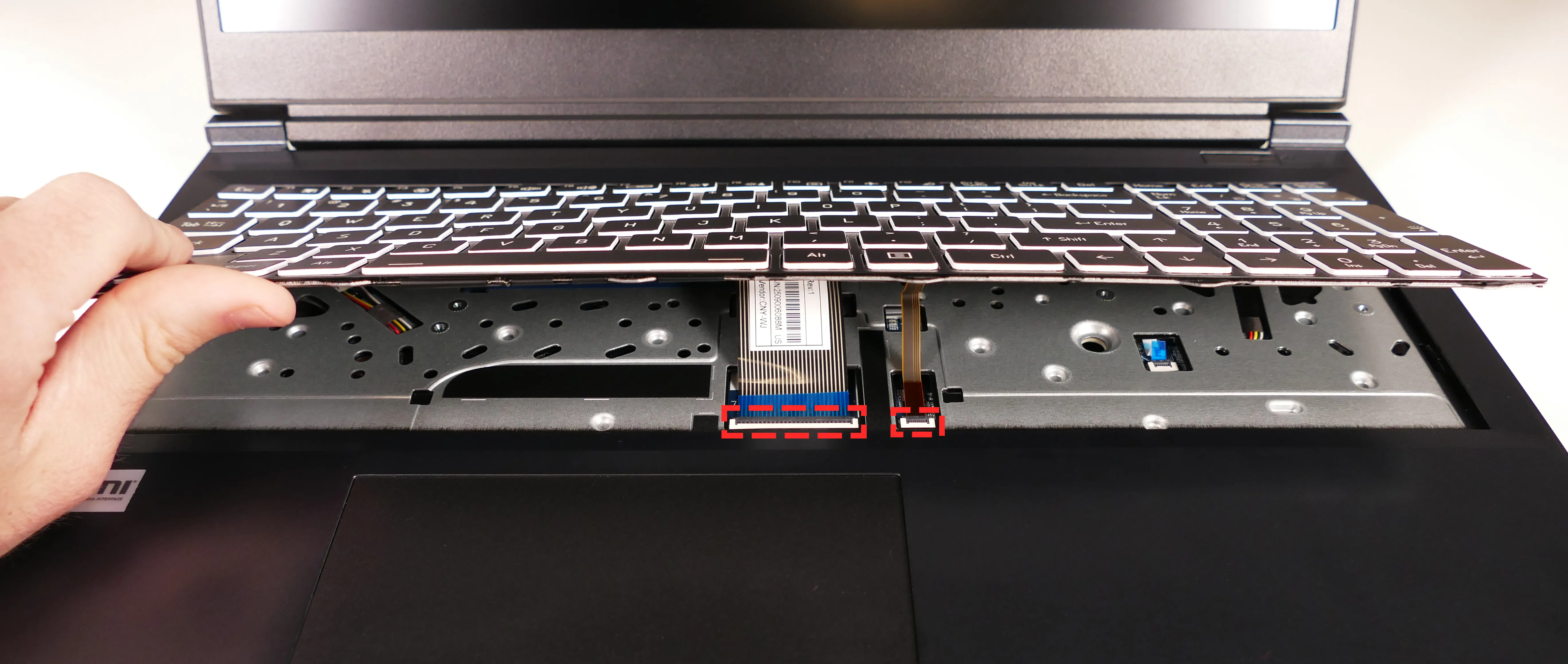
- Flip the black latches upwards to free the ribbon cables.
- Pull the ribbon cables out of the connectors.
- Remove the keyboard and replace it with the new one.
- Carefully slide both ribbon cables into their connectors.
- Flip the black latches back into place to secure the ribbon cables.
- (Optional) Replace the keyboard adhesive strip on the chassis.
- Place the keyboard back into position, starting with the tabs on the bottom edge.
- Secure the rest of the keyboard by pressing down on each of its edges.
- Turn the machine lid-side down again.
- Replace the bottom panel.
Replacing the speakers:
The system has two bottom-firing speakers, which can be removed and replaced individually.
Part numbers:
- The left speaker's model number is
V350-L-BASS, and its part number is6-23-5V350-0L0. - The right speaker's model number is
V350-R-BASS, and its part number is6-23-5V350-0R0.
Tools required: Cross-head (Phillips) screwdriver
Time estimate: 10 minutes
Difficulty: Easy ●
Steps to replace the speakers:
- Follow the steps above to remove the bottom cover.
- For the right speaker, also remove the SSD from slot 2 (the outermost slot), if installed.
- For the left speaker, you can optionally remove the main battery to make it easier to free the wire from the channels in the chassis.
- Unscrew the silver screws holding the speaker in place.
- The right speaker is secured by three screws; the left speaker is secured by two screws.
- The screws are surrounded by rubber stabilizer rings, which may hold the screws in place after they're fully unscrewed.
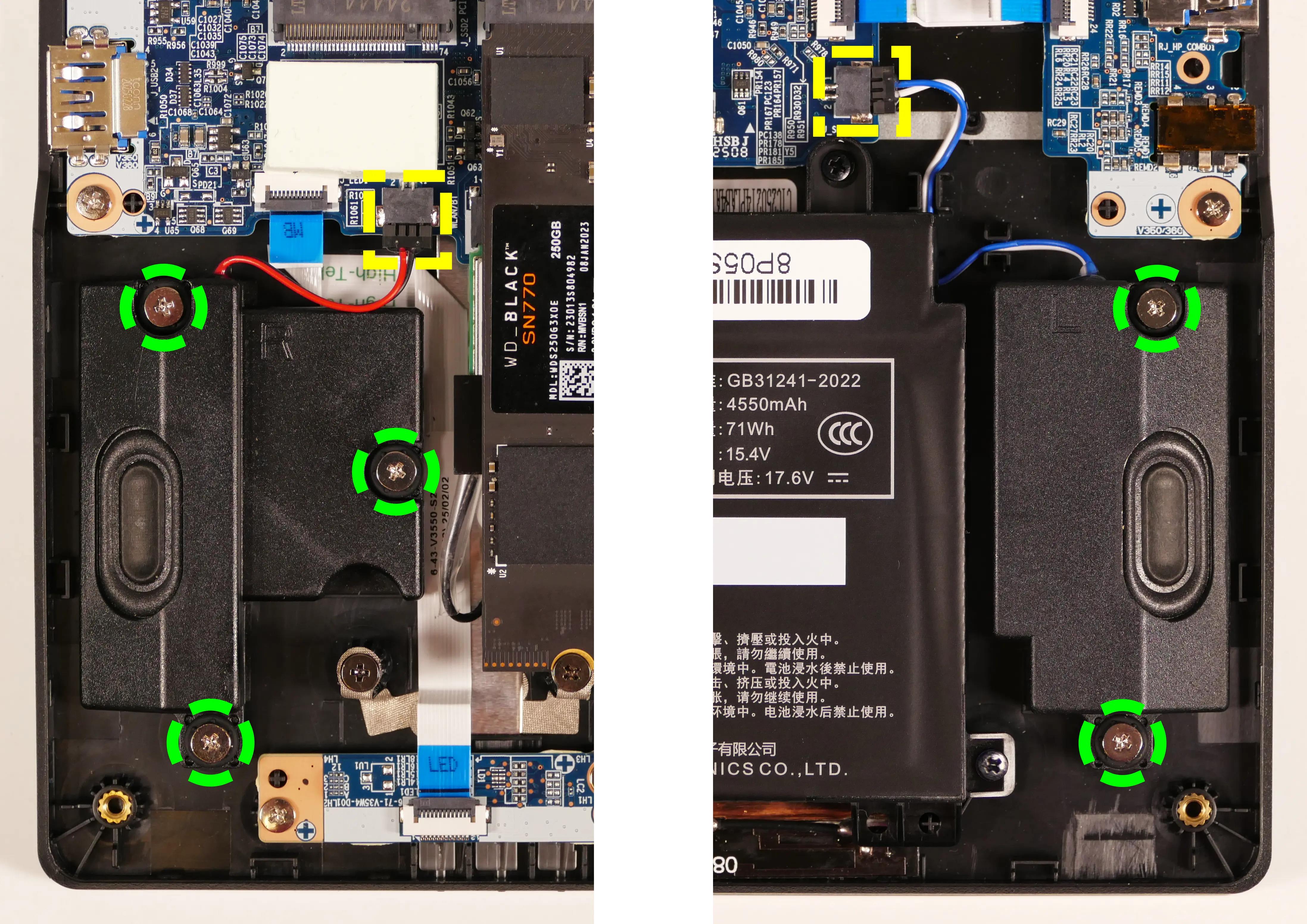
- Disconnect the speaker connector from the motherboard.
- Connect the new speaker to the motherboard and screw it into the chassis.
- Replace the outermost SSD (if necessary) and bottom cover.
Bonobo WS (bonw16)
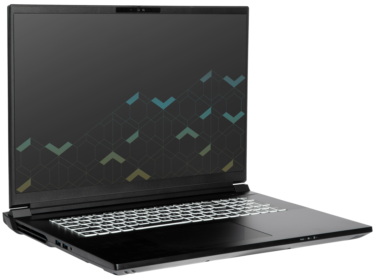
The System76 Bonobo WS is a laptop with the following specifications:
- CPU
- Supports Intel Core Ultra 2nd generation (Arrow Lake) CPUs
- Chipset
- BIOS
- Macronix MX25U25671GZ4I4G flash chip
- WSON-8 form factor
- Programmed with System76 firmware (non-open)
- Macronix MX25U25671GZ4I4G flash chip
- EC
- ITE IT5570E
- Programmed with non-open EC firmware
- Graphics
- GPU options:
- NVIDIA GeForce RTX 5090
- NVIDIA GeForce RTX 5080
- eDP display options:
- 18" 3840x2400@200Hz LCD
- LCD panel: Sharp LQ180D1JW01 (or equivalent)
- Brightness: 400 nits (cd/m²)
- DCI-P3 color coverage: 100%
- LCD panel: Sharp LQ180D1JW01 (or equivalent)
- 18" 2560x1600@240Hz LCD
- LCD panel: Sharp LQ180R1JW01 or BOE NE180QDM-NZ2 (or other equivalent)
- Brightness: 500 nits (cd/m²)
- DCI-P3 color coverage: 100%
- LCD panel: Sharp LQ180R1JW01 or BOE NE180QDM-NZ2 (or other equivalent)
- 18" 3840x2400@200Hz LCD
- External video outputs:
- 1x HDMI 2.1
- 2x DisplayPort 2.1 over USB-C
- GPU options:
- Memory
- Up to 192GB (4x48GB) dual-channel DDR5 SO-DIMMs
- Single-rank RAM and 1x dual-rank RAM speed: 4400MHz
- 2x/3x/4x dual-rank RAM speed: 4000MHz
- Up to 192GB (4x48GB) dual-channel DDR5 SO-DIMMs
- Networking
- 2.5-Gigabit Ethernet
- M.2 PCIe/CNVi WiFi/Bluetooth:
- Intel Wi-Fi 7 BE200
- Bluetooth 5.4
- Intel Wi-Fi 7 BE200
- Power
- 330W (20V, 16.5A) DC-in port
- Barrel size: 5.5mm (outer), 2.5mm (inner)
- Included AC adapter: FSP FSP330-ACAU3
- 98Wh 8-cell Lithium-Ion battery
- Model number: X580BAT-8-98
- 330W (20V, 16.5A) DC-in port
- Sound
- Internal speakers & microphone
- Combined headphone & microphone 3.5mm jack
- Combined microphone & S/PDIF (optical) 3.5mm jack
- HDMI, USB-C DisplayPort audio
- Storage
- 1x M.2 PCIe NVMe Gen 5
- 3x M.2 PCIe NVMe Gen 4
- USB
- 2x USB Type-C with Thunderbolt 5
- Both ports support DisplayPort over USB-C
- Back port supports USB-C charging (USB-PD)
- 2x USB 3.2 Gen 2 Type-A
- 2x USB Type-C with Thunderbolt 5
- Dimensions
- 40.208cm x 32.004cm x 2.794cm, 3.90kg
Bonobo WS (External Overview)
Left side:
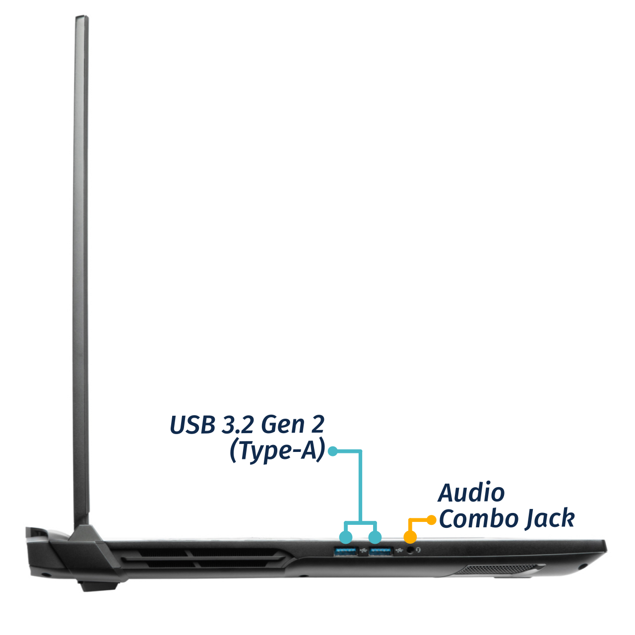
Right side:
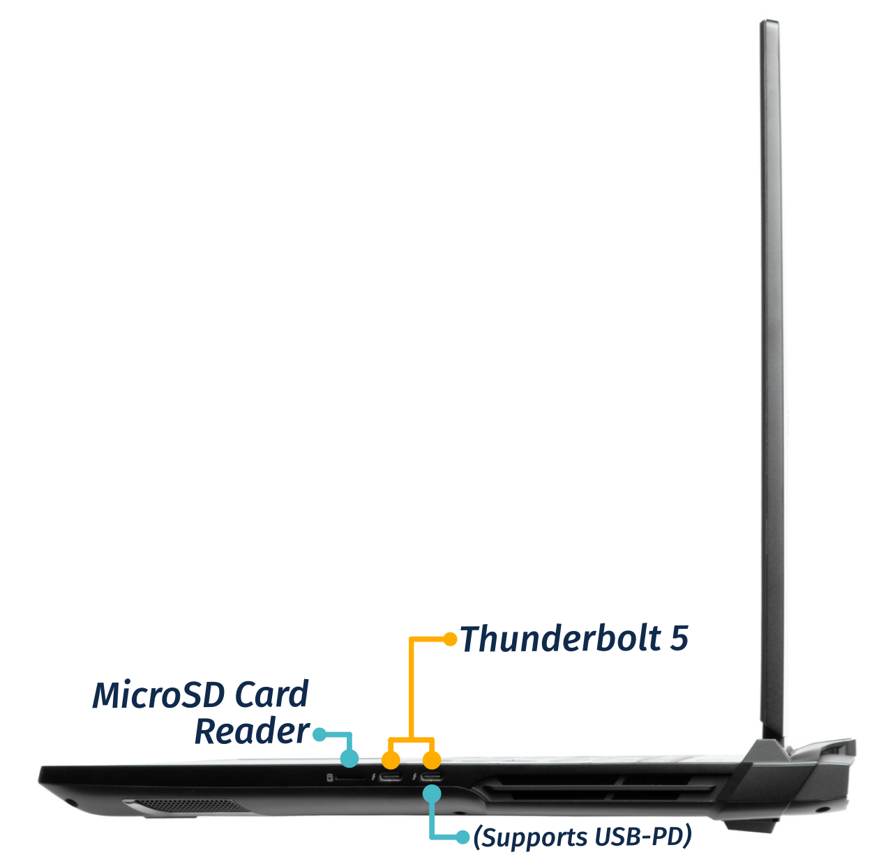
Front side:

Back side:
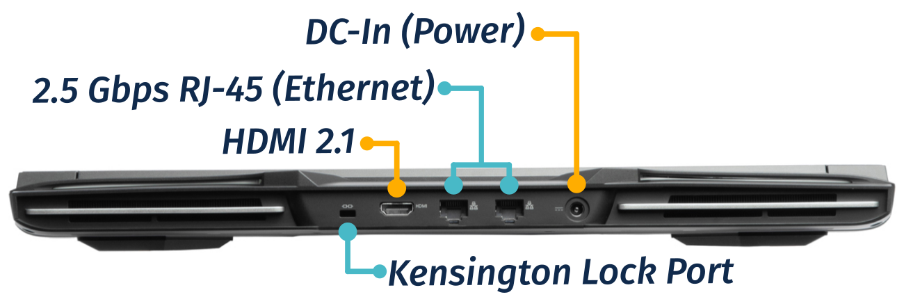
Keyboard & touchpad:
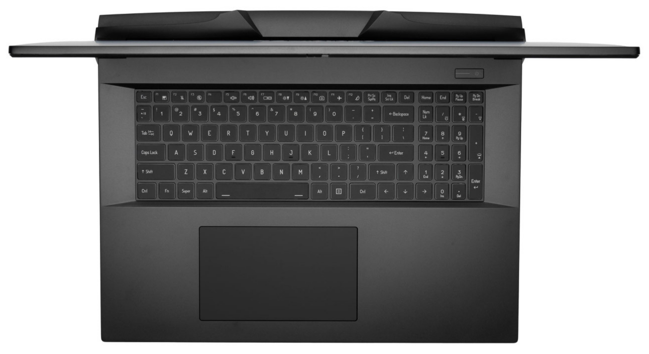
Lid:
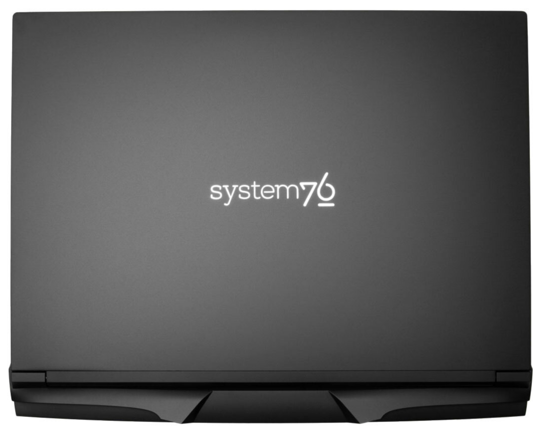
Materials:
| Part | Material | Part Number |
|---|---|---|
| LCD back cover (lid) | Aluminum | 6-39-X5801-023 |
| LCD front cover (bezel) | Plastic | 6-39-X5801-013 |
| Top case (palm rests/port covers) | Aluminum | 6-39-X5802-013 or 6-39-X5802-011-L |
| Bottom panel | Aluminum | 6-39-X5803-013 |
LED indicators
The Bonobo WS has the following LED indicators:
| Icon | Color | Description |
|---|---|---|
 | Orange | Powered off, DC power plugged in |
| Green | Powered on | |
| Blinking green | Sleeping (suspended) | |
 | Orange | Battery charging |
| Green | Battery fully charged | |
| Blinking orange | Battery critically low | |
 | Green | Storage drive activity |
Keyboard Shortcuts
The Bonobo WS has the following actions available using the Fn and Function keys:
| Key | Shortcut | Action |
|---|---|---|
 | Fn+F1 | Toggle trackpad |
 | Fn+F2 | Toggle microphone mute |
 | Fn+F3 | Mute |
 | Fn+F5 | Volume down |
 | Fn+F6 | Volume up |
 | Fn+F7 | Toggle displays |
 | Fn+F8 | Screen brightness down |
 | Fn+F9 | Screen brightness up |
 | Fn+F10 | Toggle webcam |
 | Fn+F11 | Toggle airplane mode |
 | Fn+F12 | Suspend |
 | Fn+` | Play/Pause |
 | Fn+* | Toggle keyboard backlight |
 | Fn+/ | Cycle keyboard color |
 | Fn+- | Decrease keyboard brightness |
 | Fn++ | Increase keyboard brightness |
| 1 | Fn+1 | Toggle fan between max/automatic |
Bonobo WS (Internal Overview)
Bottom components and connectors:

- LCD panel connector is highlighted in light green
- Webcam/microphone connector (under the heatsink) is highlighted in brown
- Keyboard adhesive access point is highlighted in pink
- M.2 SSDs are highlighted in dark green
- Slot 1 (closest to the fan, shown on the top-right) supports PCIe NVMe Gen 5
- Slots 2-4 support PCIe NVMe Gen 4
- Wireless card (under SSD slot 4) is highlighted in cyan
- Fan connectors are highlighted in orange
- CPU fan connector is located under SSD slot 1
- CMOS battery connector is highlighted in purple
- Speaker connectors are highlighted in yellow
- Right speaker connector (on the left) is partially under SSD slot 4
- BIOS flash chip (U98) is highlighted in black
- Main battery connector is highlighted in red
- Touchpad connector is highlighted in white
- RAM is highlighted in maroon
Under-keyboard components and connectors:

- Keyboard connector is highlighted in yellow
- Keyboard backlight connectors are highlighted in green
- Back light bar connector is highlighted in cyan
- Power button/LED connector is highlighted in red
Bonobo WS (Parts & Repairs)
Many components in your Bonobo WS can be upgraded or replaced as necessary. Follow these step-by-step guides for instructions:
- Removing the bottom cover
- Replacing the battery
- Replacing the RAM
- Replacing an M.2/NVMe SSD
- Replacing the WiFi/Bluetooth module
- Replacing the CMOS battery
- Replacing the speakers
- Replacing the fans/heatsink/thermal paste
- Replacing the keyboard
Removing the bottom cover:
Removing the cover is required to access the internal components. Prior to removing the cover, ensure the AC power is unplugged and all peripherals (such as USB drives or Kensington locks) are unplugged or removed from the system.
Part numbers:
- Bottom panel:
6-39-X5803-013
Tools required: Cross-head (Phillips) screwdriver
Time estimate: 5 minutes
Difficulty: Easy ●
Steps to remove the bottom cover:
- Place the machine lid-side down.
- Use a soft surface (such as a towel) to avoid scratches.
- Remove the 14 bottom panel screws.
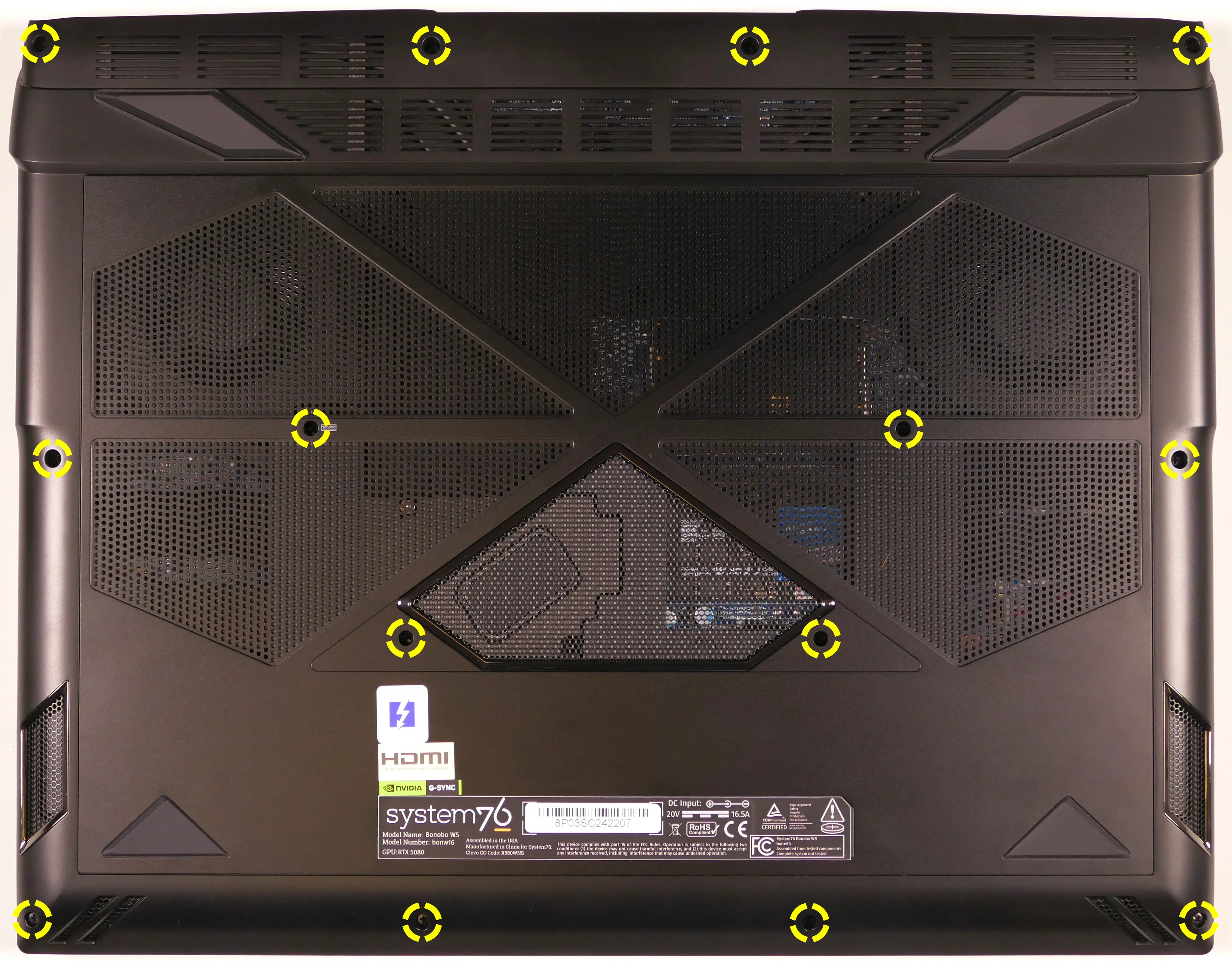
- Pull the bottom panel off, starting from the back.
Replacing the battery:
The battery provides primary power whenever the system is unplugged.
Part numbers:
- The battery's model number is
X580BAT-8-98. - The battery's original part number is
6-87-X580S-94J01. - Third-party battery sellers may list one or both of these numbers, and may offer other compatible part numbers with the same model number. You can also contact System76 to purchase a replacement battery.
Tools required: Cross-head (Phillips) screwdriver
Time estimate: 10 minutes
Difficulty: Easy ●
Steps to replace the battery:
- Follow the steps above to remove the bottom cover.
- Remove the four screws along the top of the battery.

- Unplug the white connector connecting the battery to the motherboard.
- Remove the battery, starting from the top edge with screw holes.
- When putting in the new battery, start with the plastic tabs along the bottom edge (opposite from the screw holes.)
- When plugging in the new battery, the red wire on the connector goes on the left, and the black wire goes on the right.
Replacing the RAM:
The Bonobo WS 16 supports up to 192GB (4x48GB) of DDR5 SO-DIMMs running in dual-channel configuration. The RAM speed depends on the rank and number of SO-DIMMs:
- Any number of single-rank SO-DIMMs will run at a speed of 4400MHz.
- The 2x16GB (32GB total) factory configuration runs at this speed.
- A single dual-rank SO-DIMM will run at 4400MHz.
- This configuration is not recommended because running in single-channel mode will result in lower performance than the equivalent capacity running in dual-channel mode at a slightly lower speed.
- More than one dual-rank SO-DIMM will run at 4000MHz.
- All other factory configurations run at this speed.
If you've purchased new RAM, need to replace your RAM, or are reseating your RAM, follow these steps.
Tools required: Cross-head (Phillips) screwdriver
Time estimate: 10 minutes
Difficulty: Easy ●
Steps to replace the RAM:
- Follow the steps above to remove the bottom cover.
- Press the small tabs on both sides of the RAM apart from each other simultaneously. The RAM should spring up to an angle.

- Remove the RAM from the slot.
- Insert the new RAM (or reseat the existing RAM) by placing it in the keyed slot and pressing down on the RAM until it clicks into place.
- Either two or four SO-DIMMs (RAM sticks) are required. Using one or three SO-DIMMs is not supported.
- If you're installing only two SO-DIMMs, place them on top of each other (within the same colored box as shown above)-- i.e. in slots 1 and 2 (highlighted yellow), or in slots 3 and 4 (highlighted cyan).
Replacing an M.2/NVMe SSD:
This model supports up to four M.2 SSDs of size 2280. Slot 1 (nearest the fan) supports PCIe NVMe Gen 5; the other slots support PCIe NVMe Gen 4.
Tools required: Cross-head (Phillips) screwdriver
Time estimate: 10 minutes
Difficulty: Easy ●
Steps to replace the M.2 drive:
- Follow the steps above to remove the bottom cover.
- Unscrew the retainer screw opposite the M.2 slot.

- Remove the existing M.2 drive by pulling it out of the slot.
- Insert the new M.2 drive into the slot and hold it in place.
- Replace the retainer screw.
Replacing the wireless card:
Your Bonobo WS's WiFi and Bluetooth are both handled by the same module. It is a standard M.2 2230 slot with PCIe and USB interfaces (E-key).
Part numbers:
- Default wireless card: Intel
BE200
Tools required: Cross-head (Phillips) screwdriver
Time estimate: 10 minutes
Difficulty: Medium ●
Steps to replace the WiFi/Bluetooth module:
- Follow the steps above to remove the bottom cover and remove the M.2 SSD from slot 4 (if installed).
- Unscrew the wireless card screw holding the card and its wire bracket in place.
- The card will lift up at an angle once unscrewed.

- Remove the metal bracket that holds the wires onto the card.
- Gently remove the two antennas (highlighted red below) by pulling them up and away from the wireless card.

- Remove the card from the M.2 slot.
- Insert the new wireless card into the M.2 slot at an angle.
- Hold the card down and attach the two antennas by aligning the circular fittings and pressing onto the wireless card. The connectors will snap into place. Use caution when attaching the connectors; the pins can bend, break, or snap.
- Replace the metal bracket and the retaining screw.
- Replace the M.2 SSD in slot 4 (if necessary) and bottom panel.
Replacing the CMOS battery:
The CMOS battery supplies power to the system's CMOS chip. UEFI settings and the comptuer's hardware clock are stored on the CMOS. If your system doesn't boot, you can reset the CMOS to force a low-level hardware reset. If your clock is constantly resetting, it's likely your CMOS battery needs to be replaced.
Warning (ingestion hazard): Keep batteries out of reach of children. Death or serious injury can occur if ingested. If a battery is suspected to be swallowed or inserted inside any part of the body, seek immediate medical attention. In the US, you can also call the National Battery Ingestion Hotline for guidance: +1 (800) 498-8666
Part numbers:
- The CMOS battery is a standard 3V KTS CR2032W battery.
Tools required: Cross-head (Phillips) screwdriver
Time estimate: 10 minutes
Difficulty: Easy ●
Steps to replace the CMOS battery:
- Follow the steps above to remove the bottom cover.
- If you're clearing the CMOS, also unplug the main battery.
- Unplug the white connector that connects the CMOS battery to the motherboard's
J_RTC1port (near SSD slot 2).- If you're replacing the battery, gently pull it up from where it's stuck to the case.

- To clear the CMOS, open the lid of the machine and hold down the power button for at least 15 seconds to discharge any residual energy in the system.
- Re-connect the CMOS battery and the main battery.
- Power up the Bonobo WS. The system may power itself off and on after initial boot; this is normal behavior when the CMOS has been reset.
Replacing the speakers:
The system has three bottom-firing speakers, which can be removed and replaced individually.
Part numbers:
- Subwoofer:
6-23-5X580-0W2 - Left speaker:
6-23-5X580-0L2 - Right speaker:
6-23-5X580-0R2
Tools required: Cross-head (Phillips) screwdriver
Time estimate: 10 minutes
Difficulty: Medium ●
Steps to replace the subwoofer:
- Follow the steps above to remove the bottom cover.
- Remove the four silver screws holding the subwoofer onto the heatsink.
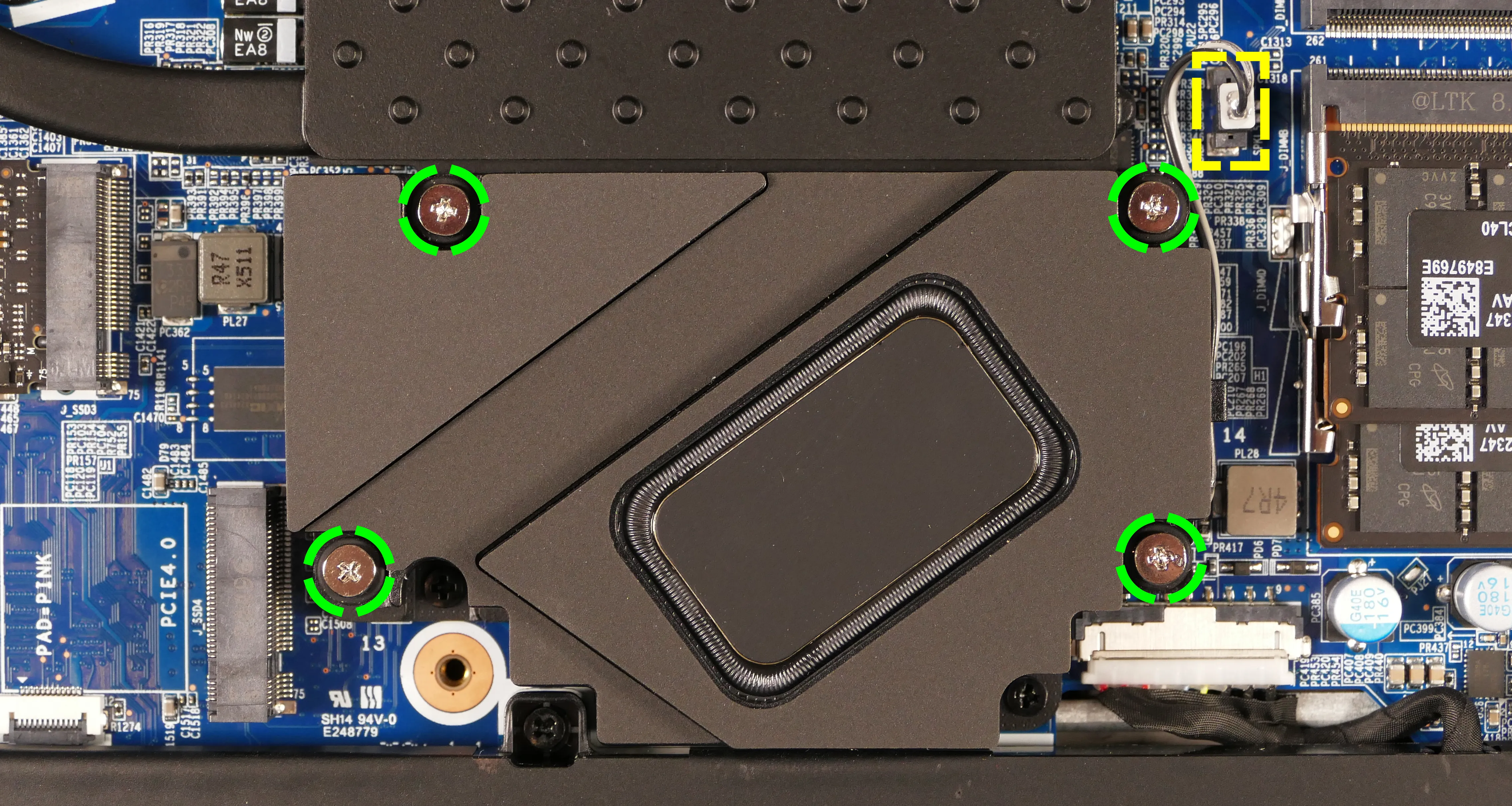
- Unplug the subwoofer from the
J_SPKL5port on the motherboard and remove it from the chassis. - Replace the subwoofer and bottom cover.
Steps to replace the left and right speakers:
- Follow the steps above to remove the bottom cover.
- For the right speaker, also remove the M.2 SSD from slot 4 (if installed).
- Pull the speaker(s) off of the plastic posts.
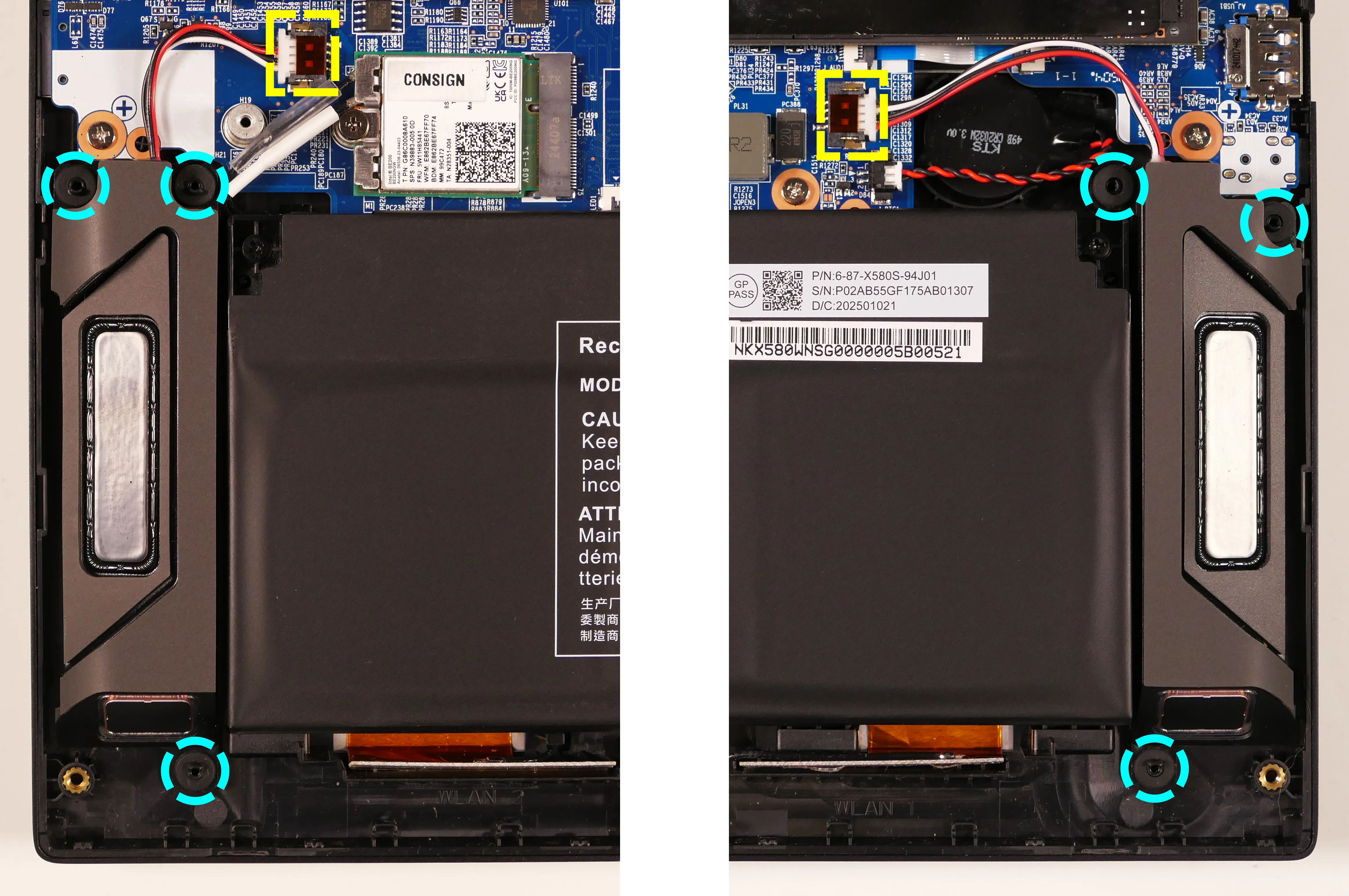
- Disconnect the speaker connector(s) from the motherboard.
- The left speaker (pictured on the right above) connects to
J_SPK1. - The right speaker (pictured on the left) connects to
J_SPK2.
- The left speaker (pictured on the right above) connects to
- Replace the speaker(s) and bottom cover.
Replacing the cooling system:
The Bonobo WS 16 has a single heatsink assembly with two fans. This assembly cools the CPU and GPU.
If the fans become noisy and cleaning them out doesn't fix the issue, you may need a new fan. Contact support to start a warranty claim or parts purchase. These instructions can also be used if physical damage to the heatsink necessitates its replacement.
Thermal paste helps facilitate effective heat transfer between the CPU/GPU and the cooling equipment; depending on your climate and the age of the machine, replacing the thermal paste may improve cooling performance. The thermal paste should generally be replaced whenever the heatsink is removed.
Thermal putty (thicker than thermal paste) is used to bridge the gap between the VRAM chips and the heatsink. Replacing the thermal putty is optional when removing the heatsink. System76 suggests Thermal Grizzly Putty Basic (available at various retailers) or a similar alternative.
Part numbers:
- Heatsink/fan assembly:
6-31-X580N-101 - Individual fans (may not be available separately):
- Left fan: Yingfan
NA901212HHT4B10001 DX1 - Right fan: Yingfan
NB901212HHT4B0001 DX2
- Left fan: Yingfan
Tools required: Cross-head (Phillips) screwdriver, thermal putty spreader (flat plastic tool)
Time estimate: 15 minutes
Difficulty: High ●
Steps to replace the heatsink/thermal paste:
- Follow the steps above to remove the bottom cover and remove the SSD from slot 1 (if installed).
- Disconnect the subwoofer from the motherboard's
J_SPKL5header.- You can optionally remove the subwoofer. In the photo below, the subwoofer has been removed to better illustrate the location of the heatsink screws.
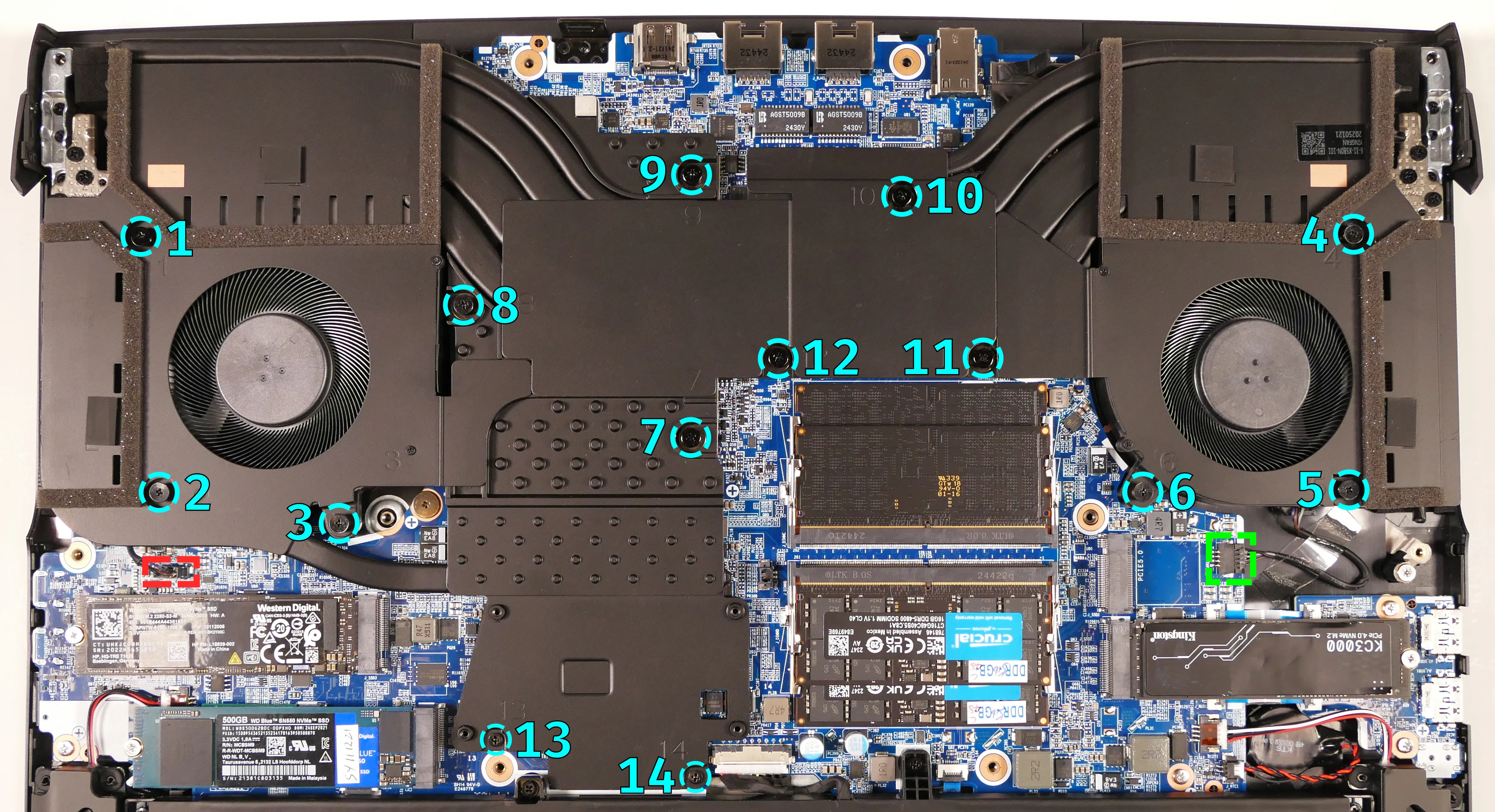
- Remove the fourteen heatsink and fan screws in order of the stamped numbers, starting with #1, then #2, and continuing until you have removed #14.
- Screws #1-#12 are held captive, and will not completely detatch from the heatsink/fans.
- Screws #13 and #14 are slightly smaller than the rest of the screws, and are not held captive.
- Do not remove the smaller screws holding the fan covers onto the fans.
- Remove any clear tape covering the fan wires.
- Unplug the black fan connectors from the motherboard's fan headers,
J_VGAFAN1(highlighted red above) andJ_CPUFAN1(highlighted green). - Remove the heatsink/fans from the case, being careful not to bend the heatsink pipes. It may take some pressure to break the seal of the thermal paste.
- Using a paper towel, remove the existing thermal paste from the CPU, GPU, and heatsink. You may also use a small amount of rubbing alcohol if the old paste is dried or difficult to remove.
- In the below photos, the subwoofer is screwed into the heatsink, so its cable is visible in addition to the fan cables.
- You can optionally remove the thermal putty from the eight VRAM chips surrounding the GPU chip if you have replacement thermal putty to install.

- Apply a small line of thermal paste directly onto the CPU chip and the GPU chip.
- If you're also replacing the thermal putty, apply the new putty to the eight VRAM chips.
- If you aren't replacing the thermal putty, scoop the existing putty (from the VRAM chip and the corresponding location on the heatsink) into the center of each VRAM chip using a flat plastic tool.

- Carefully replace the heatsink.
- Make sure the tab on the end of the keyboard adhesive strip (highlighted green above) is fed through the slot in the heatsink (next to the GPU fan).
- Tighten the fan and heatsink screws from #1 to #12, then reinstall the final two heatsink screws (#13 and #14).
- Plug the black fan connectors back into the motherboard and (optionally) replace the clear tape holding down the CPU fan's cable.
Replacing the keyboard:
The keyboard includes per-key RGB LED backlighting, and can be replaced using the instructions below.
Warning: Removing the keyboard may cause permanent aesthetic damage to the underside of the keyboard, particularly if the adhesive strip is not fully removed first. Removal is not recommended unless the keyboard is malfunctioning.
Part numbers:
- Keyboard:
- Model number:
6-X580[D]WNT-G-KB-LPK-US, also known asCVM18H93US9430FA - Part number:
6-80-PC510-013-1MD
- Model number:
Tools required: Cross-head (Phillips) screwdriver; tweezers (optional)
Time estimate: 10 minutes
Difficulty: High ●
Steps to replace the keyboard:
- Follow the steps above to remove the bottom cover.
- Pull the keyboard adhesive out of the machine to detatch it from the keyboard.
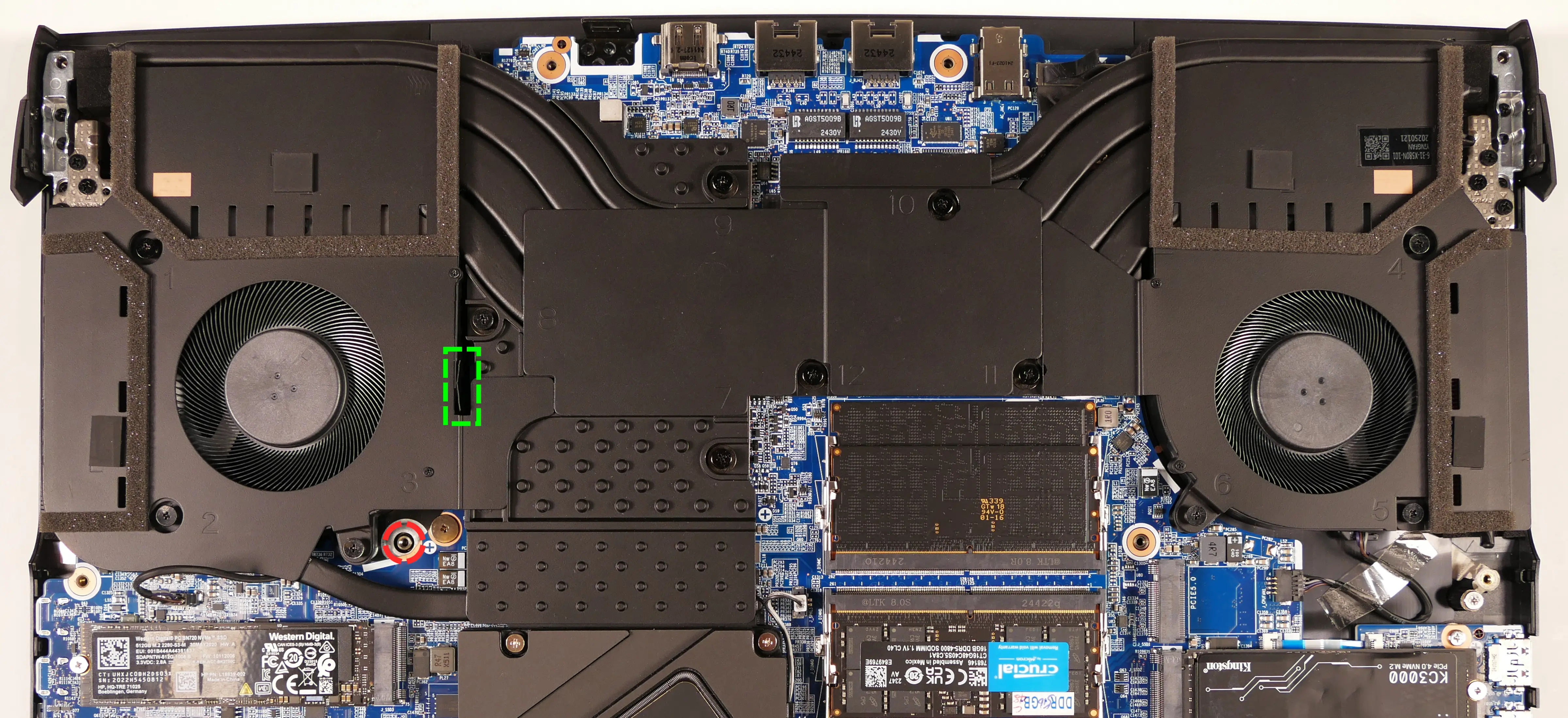
- The adhesive strip access point is highlighted green below.
- If the end of the keyboard adhesive strip is tucked behind the fan, it can be pulled out using tweezers or a small screwdriver, or the thermal system can be removed to expose it.
- Replacing the thermal paste is recommended if the thermal system is removed.
- If the adhesive strip breaks, remove as much of it as possible. The keyboard can be reinstalled without the adhesive strip.
- Open the lid slightly and place the machine on its side.
- Push a screwdriver into the keyboard push point (highlighted red above) until the keyboard pops out.

- Set the machine back down and raise the keyboard away from the chassis. The largest ribbon cable is for the keyboard, while the smaller ribbon cables are for the keyboard backlight.

- Flip the black latches upwards to free the ribbon cables.
- Pull the ribbon cables out of the connectors.
- Remove the keyboard and replace it with the new one.
- Carefully slide all three ribbon cables into their connectors.
- Flip the black latches back into place to secure the ribbon cables.
- (Optional) Replace the keyboard adhesive strip on the chassis, sliding the tab at the end through the adhesive strip access point.
- Place the keyboard back into position, starting with the tabs on the bottom edge.
- Secure the rest of the keyboard by pressing down on each of its edges.
- Turn the machine lid-side down again.
- Replace the bottom cover.
Darter Pro (darp11 & darp11-b)
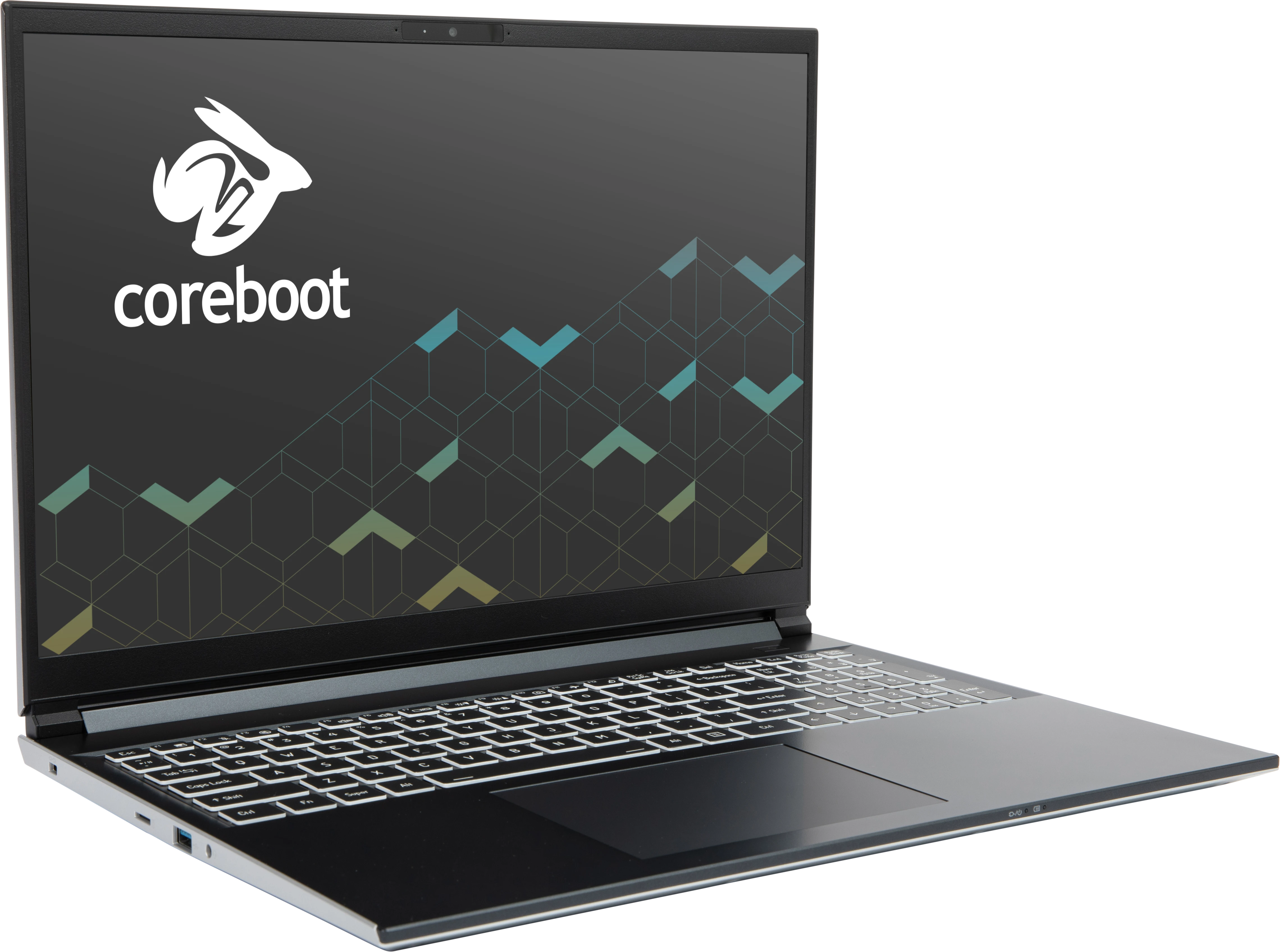
The System76 Darter Pro is a laptop with the following specifications:
- CPU
- Supports Intel Core Ultra 2nd generation (Arrow Lake) CPUs
- BIOS
- XMC XM25QU256CXIQT08S flash chip
- WSON-8 form factor
- Programmed with System76 Open Firmware
- Motherboard part number:
- 16" (darp11):
6-77-V560TU00-D02-4F#10 - 14" (darp11-b):
6-77-V540TU10-D02-2F#10
- 16" (darp11):
- XMC XM25QU256CXIQT08S flash chip
- EC
- ITE IT5570E
- Programmed with System76 EC
- Graphics
- GPU: Intel Arc Graphics (dependent on CPU)
- Core Ultra 7-255H: Intel Arc 140T GPU
- Core Ultra 5-225H: Intel Arc 130T GPU
- eDP display:
- 16" 1920x1200@60Hz LCD (darp11)
- LCD panel: AUO B160UAN03.0 (or equivalent)
- Brightness: 250 nits (cd/m²)
- sRGB color coverage: 65%
- LCD panel: AUO B160UAN03.0 (or equivalent)
- 14" 1920x1200@60Hz LCD (darp11-b)
- LCD panel: Innolux N140JCA-ELL (or equivalent)
- Brightness: 300 nits (cd/m²)
- sRGB color coverage: 66%
- LCD panel: Innolux N140JCA-ELL (or equivalent)
- 16" 1920x1200@60Hz LCD (darp11)
- External video outputs:
- 1x HDMI 2.1
- 1x DisplayPort 2.1 over USB-C
- GPU: Intel Arc Graphics (dependent on CPU)
- Memory
- Up to 96GB (2x48GB) dual-channel DDR5 SO-DIMMs @ 5600 MHz
- Networking
- Gigabit Ethernet
- M.2 PCIe/CNVi WiFi/Bluetooth:
- Intel Wi-Fi 7 BE200
- Bluetooth 5.4
- Intel Wi-Fi 7 BE200
- Power
- 90W (19V, 4.74A) DC-in port
- Barrel size: 5.5mm (outer), 2.5mm (inner)
- Included AC adapter: Chicony A16-090P1A
- AC power cord type: IEC C5
- USB-C charging compatible with 90W+ charger
- 73Wh 4-cell Lithium-ion battery
- Model number: V540BAT-4-73
- 90W (19V, 4.74A) DC-in port
- Sound
- Internal speakers & microphone
- Combined headphone & microphone 3.5mm jack
- HDMI, USB-C DisplayPort audio
- Storage
- 2x M.2 (PCIe NVMe Gen 4)
- MicroSD card reader
- USB
- 1x USB Type-C with Thunderbolt 4
- Supports DisplayPort over USB-C
- Supports USB-C charging (USB-PD)
- 1x USB 3.2 Gen 2 Type-C
- 1x USB 3.2 Gen 2 Type-A
- 1x USB 3.2 Gen 1 Type-A
- 1x USB Type-C with Thunderbolt 4
- Dimensions
- 16" model (darp11): 1.8cm x 35.8cm x 25.86cm, 1.93kg
- 14" model (darp11-b): 1.8cm x 31.7cm x 23.5cm, 1.59kg
Darter Pro (External Overview)
Left side:
16" model (darp11):
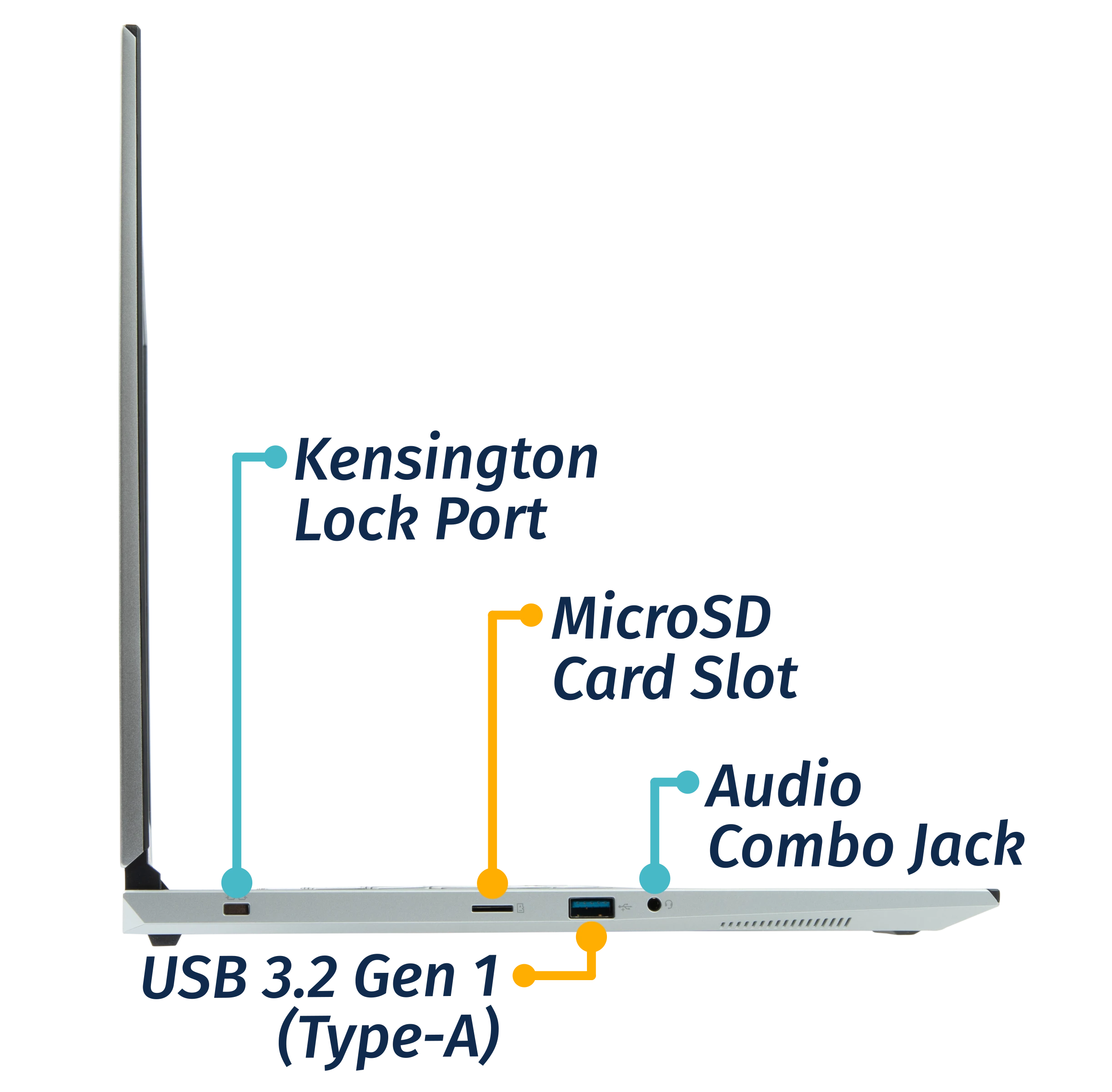
14" model (darp11-b):
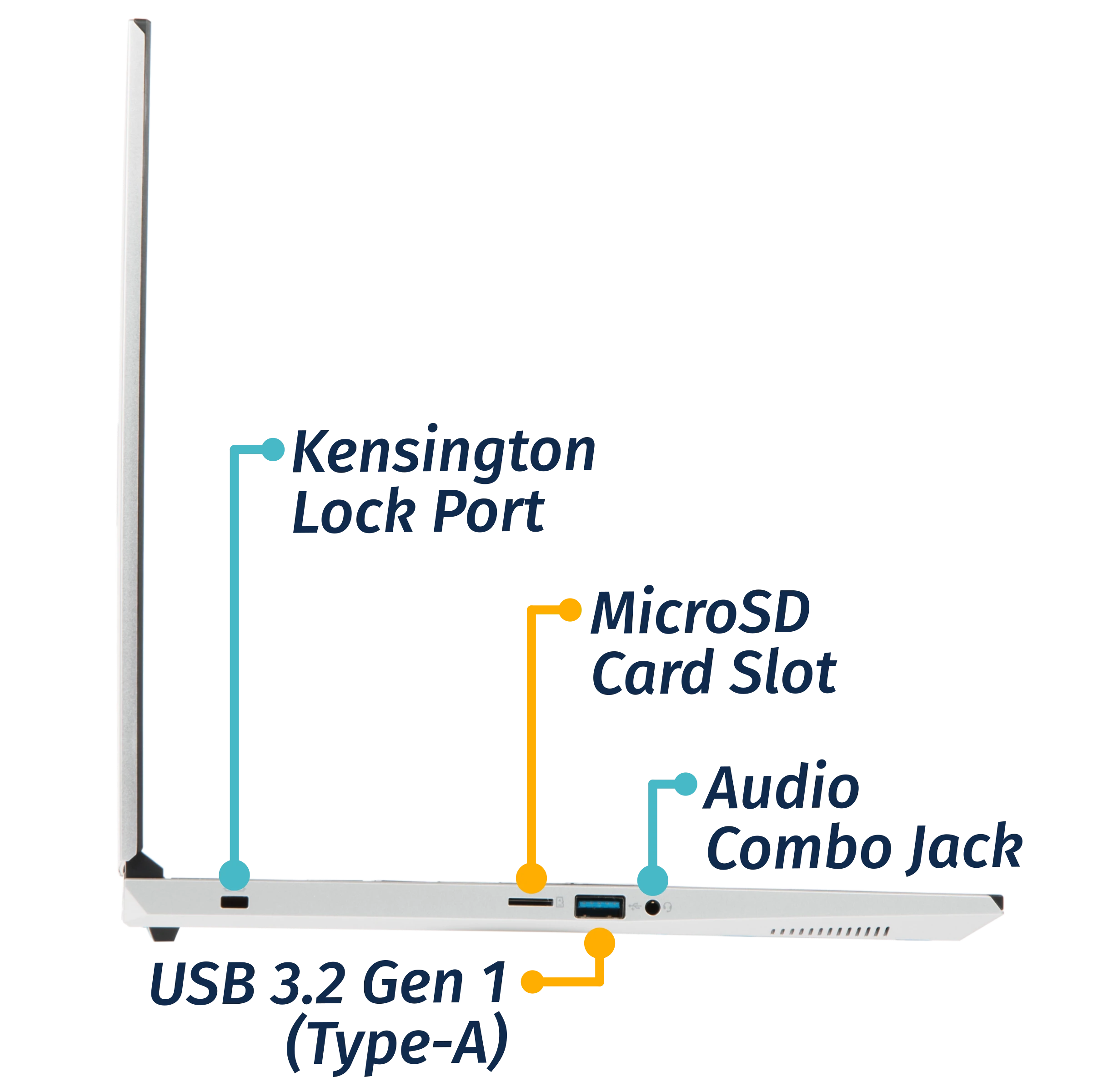
Right side:
16" model (darp11):
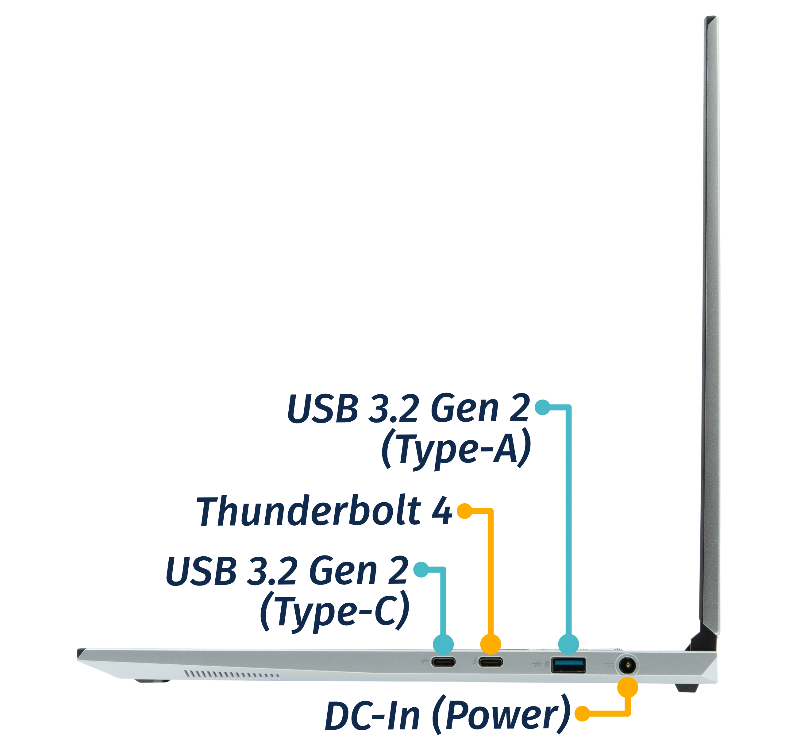
14" model (darp11-b):
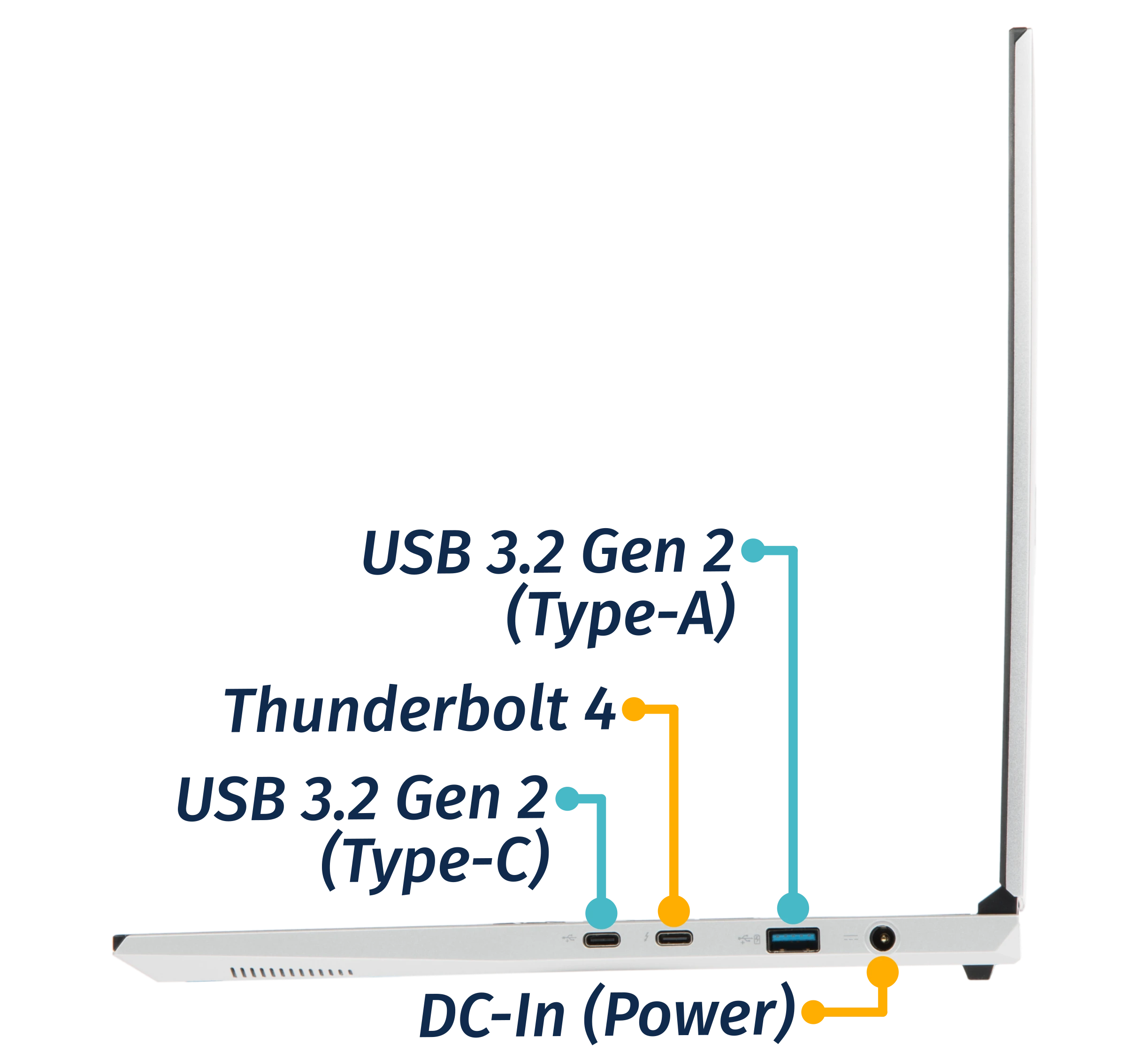
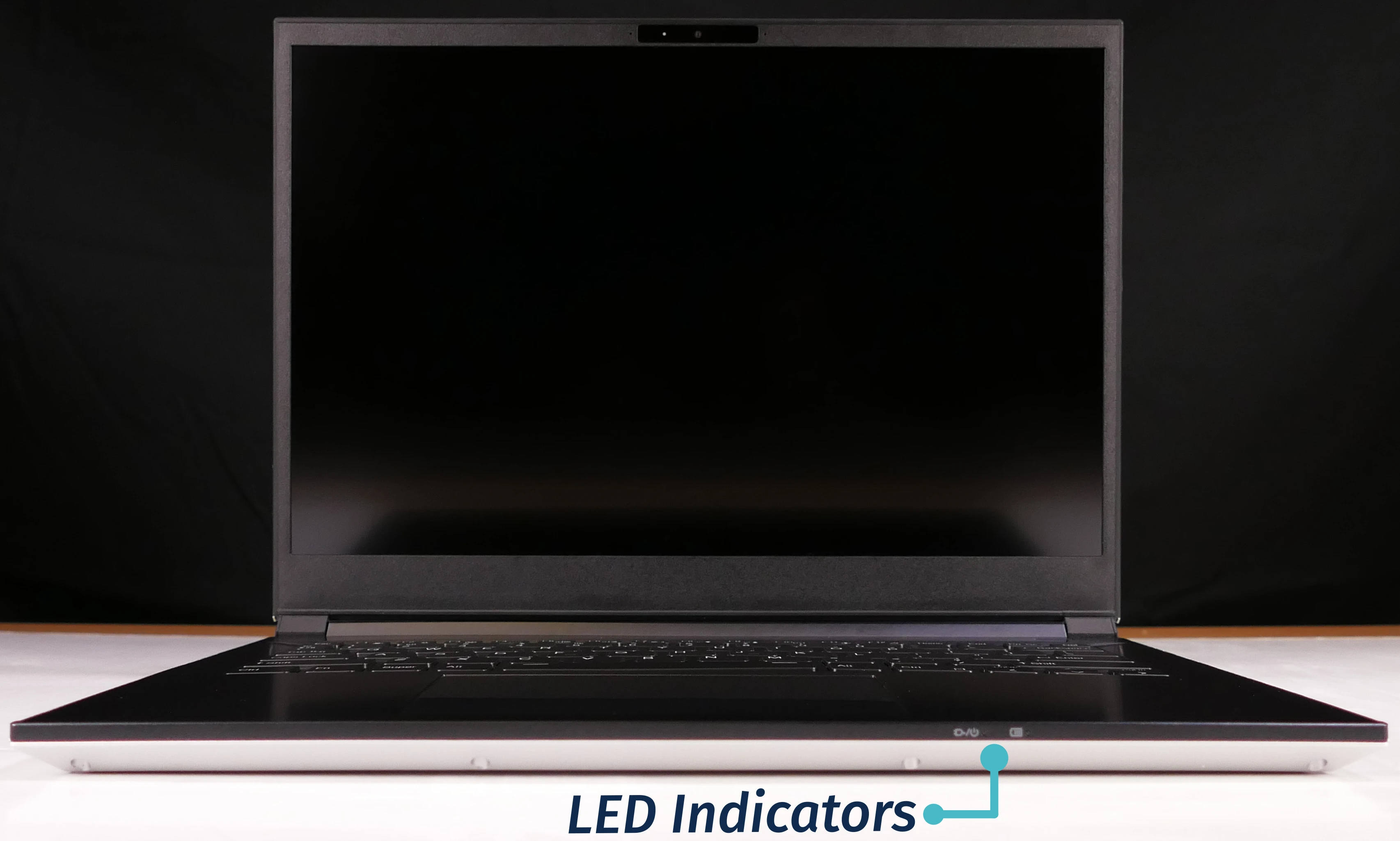
Front side:
16" model (darp11):

14" model (darp11-b):
Back side:
16" model (darp11):

14" model (darp11-b):

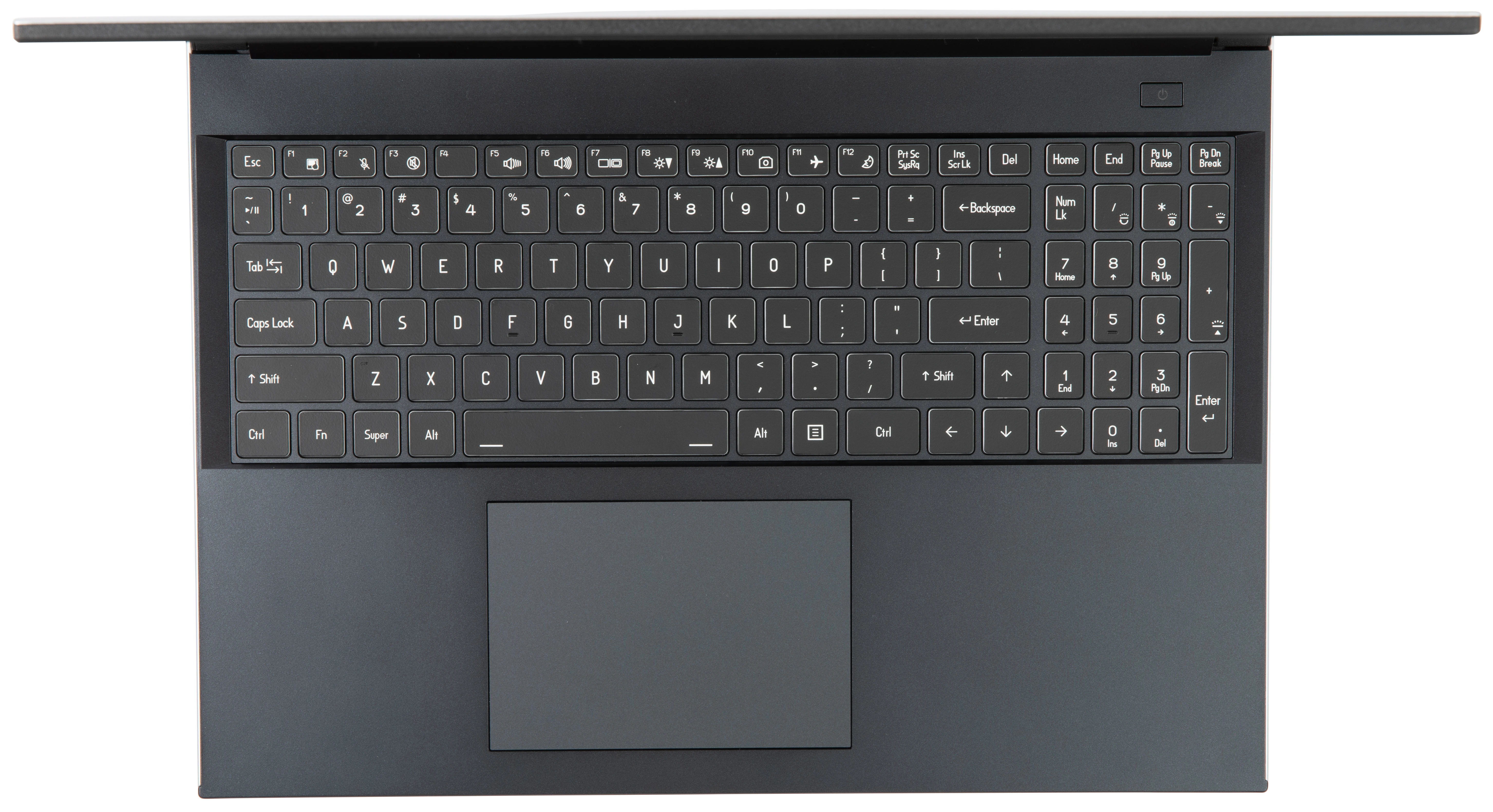
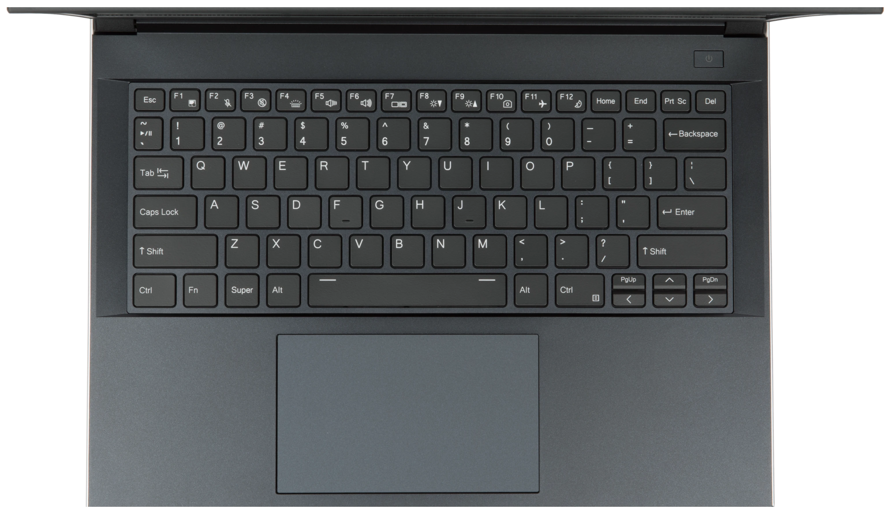
Keyboard & touchpad:
16" model (darp11):
14" model (darp11-b):
Lid:

Materials:
| Part | Material | Part Number |
|---|---|---|
| LCD back cover (lid) | Aluminum | 16" (darp11): 6-39-V56T1-022 14" (darp11-b): 6-39-V54T1-022 |
| LCD front cover (bezel) | Plastic | 16" (darp11): 6-39-V5601-012 14" (darp11-b): 6-39-V5401-012 |
| Top case (palm rests/port covers) | Plastic | 16" (darp11): 6-39-V5602-012 14" (darp11-b): 6-39-V5402-012 |
| Bottom panel | Aluminum | 16" (darp11): 6-39-V56T3-012 14" (darp11-b): 6-39-V54T3-012 |
LED indicators:
| Icon | Color | Description |
|---|---|---|
 | Orange | Powered off, DC power plugged in |
| Green | Powered on | |
| Blinking green | Sleeping (suspended) | |
 | Orange | Battery charging |
| Green | Battery fully charged |
Keyboard shortcuts:
| Key | Shortcut | Action |
|---|---|---|
 | Fn+F1 | Toggle trackpad |
 | Fn+F2 | Mic mute |
 | Fn+F3 | Mute |
 | Fn+F4 | 14" model (darp11-b): Toggle keyboard backlight |
 | Fn+F5 | Volume down |
 | Fn+F6 | Volume up |
 | Fn+F7 | Toggle displays |
 | Fn+F8 | Screen brightness down |
 | Fn+F9 | Screen brightness up |
 | Fn+F10 | Toggle webcam |
 | Fn+F11 | Toggle airplane mode |
 | Fn+F12 | Suspend |
 | Fn+` | Play/Pause |
 | Fn+* | 16" model (darp11): Toggle keyboard backlight |
 | Fn+/ | 16" model (darp11): Cycle keyboard brightness levels |
 | Fn+- | 16" model (darp11): Decrease keyboard brightness |
 | Fn++ | 16" model (darp11): Increase keyboard brightness |
| 1 | Fn+1 | Toggle fan between max/automatic |
Darter Pro (Internal Overview)
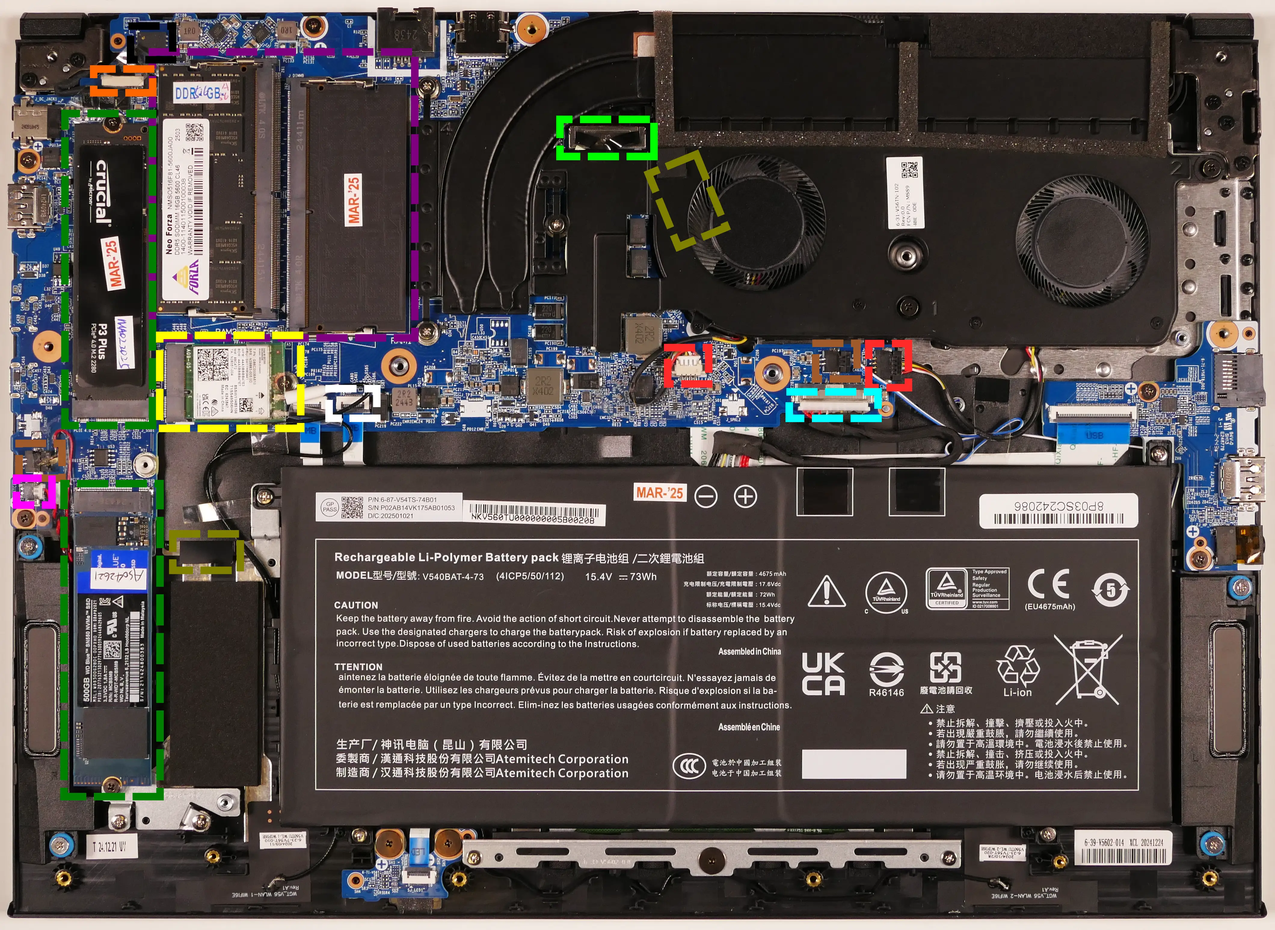
Bottom components and connectors:
16" model (darp11):
14" model (darp11-b):
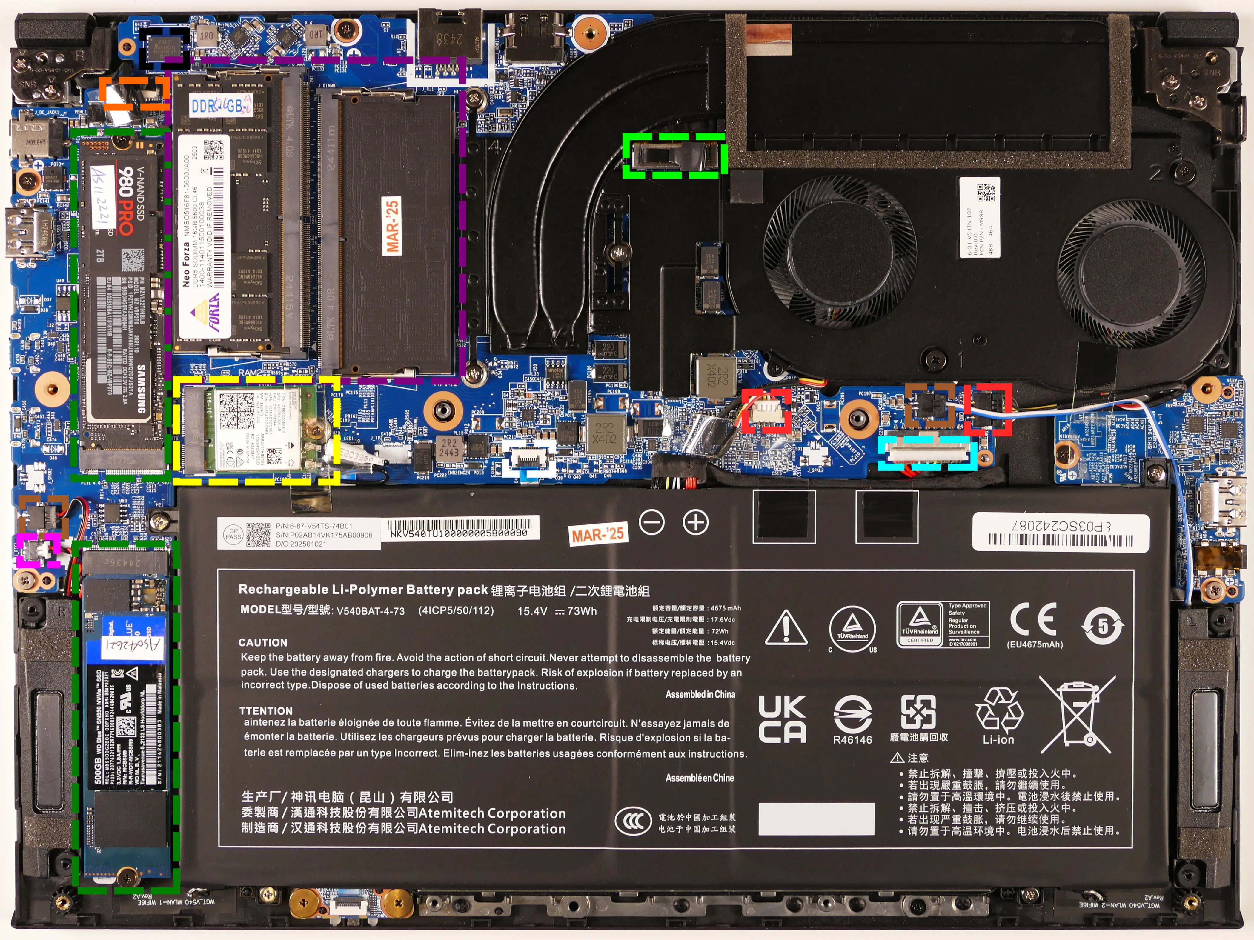
- RAM slots are highlighted in purple
- Wireless card is highlighted in yellow
- Fan connectors are highlighted in red
- Webcam/microphone connector is highlighted in orange
- M.2 SSDs are highlighted in dark green
- Both slots support PCIe NVMe Gen 4
- CMOS battery connector is highlighted in pink
- Main battery connector is highlighted in cyan
- LCD panel connector is highlighted in light green
- Speaker connectors are highlighted in brown
- Touchpad connector is highlighted in white
- Keyboard adhesive strip access slots are highlighted in olive (16" model only)
- Rightmost slot is underneath the fan/heatsink assembly
- BIOS flash chip (U43) is highlighted in black
Under-keyboard components and connectors:
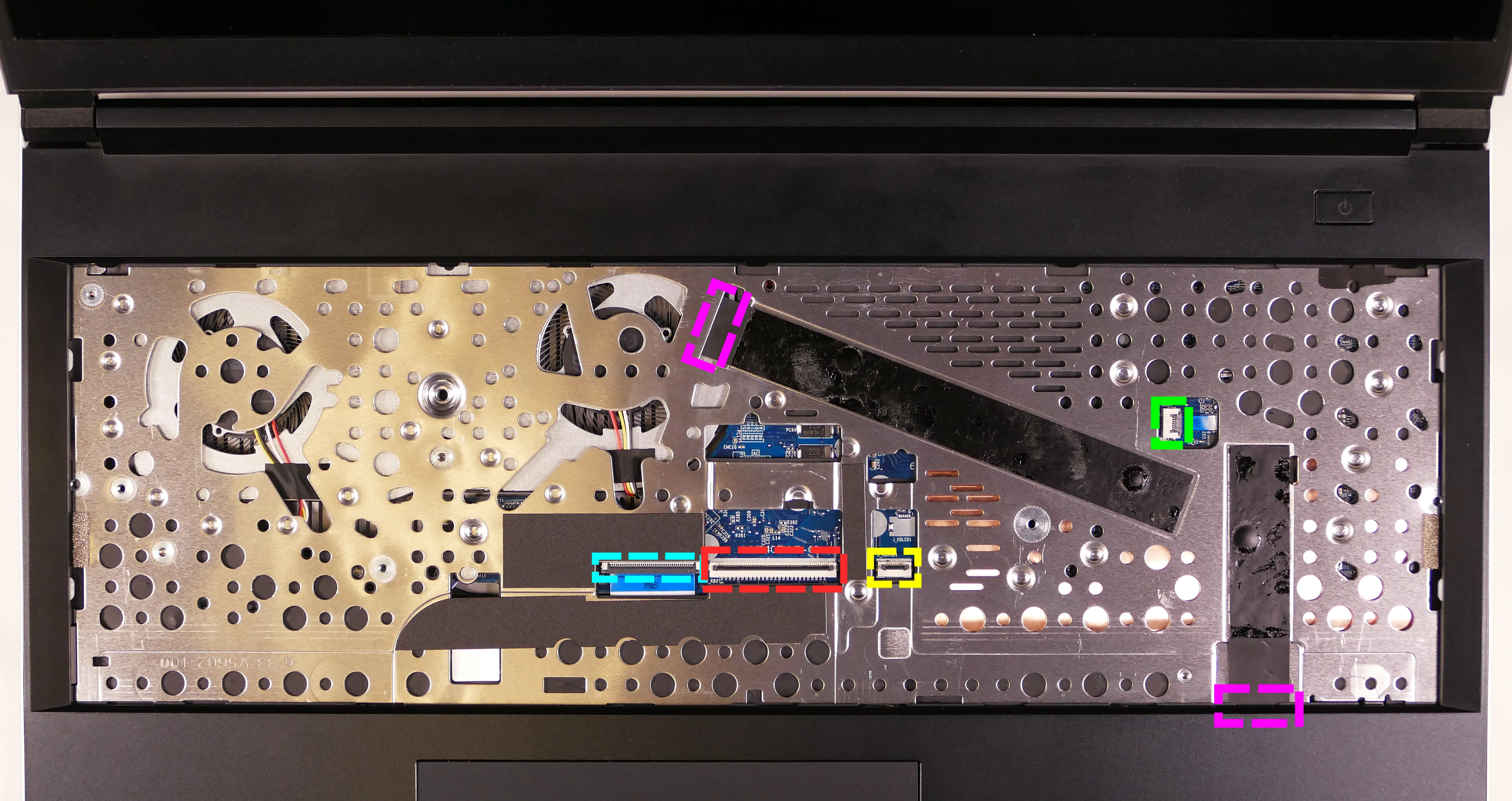
16" model (darp11):
14" model (darp11-b):
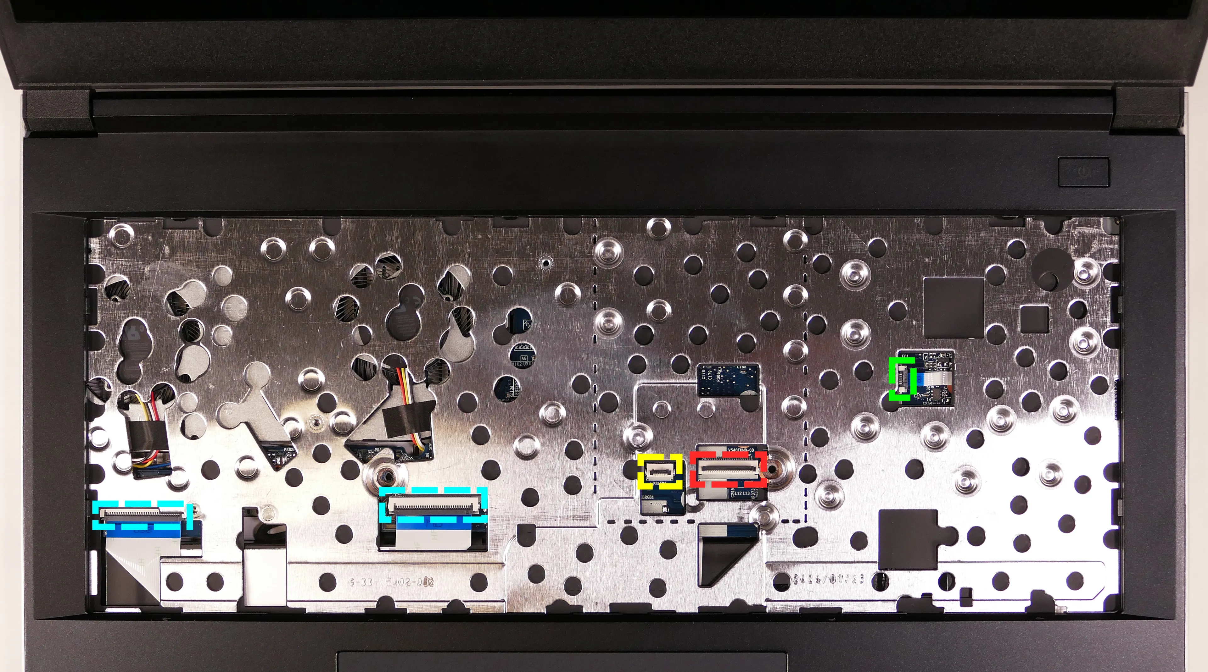
- Keyboard connector is highlighted in red
- Keyboard backlight connector is highlighted in yellow
- Audio/USB board connectors are highlighted in cyan
- Power button/LED connector is highlighted in green
- Adhesive strip access slots are highlighted in pink (16" model only)
Darter Pro (Parts & Repairs)
Many components in your Darter Pro can be upgraded or replaced as necessary.
This page contains photos and part numbers for both the 16" model (darp11) and the 14" model (darp11-b). Unless otherwise noted, photos are of the 14" model (darp11-b), and general component locations are the same between both models.
Follow these step-by-step guides for instructions:
- Removing the bottom cover
- Replacing the RAM
- Replacing an M.2/NVMe SSD
- Replacing the WiFi/Bluetooth module
- Replacing the CMOS battery
- Replacing the fans/heatsink/thermal paste
- Replacing the speakers
- Replacing the keyboard
- Replacing the battery
Removing the bottom cover:
Removing the cover is required to access the internal components. Prior to removing the cover, ensure the AC power is unplugged and all peripherals (including SD cards and USB drives) are unplugged or removed from the system.
Part numbers:
- 16" (darp11) bottom panel:
6-39-V56T3-012 - 14" (darp11-b) bottom panel:
6-39-V54T3-012
Tools required: Cross-head (Phillips) screwdriver
Time estimate: 7 minutes
Difficulty: Easy ●
Steps to remove the bottom cover:
- Place the machine lid-side down.
- Use a soft surface (such as a towel) to avoid scratches.
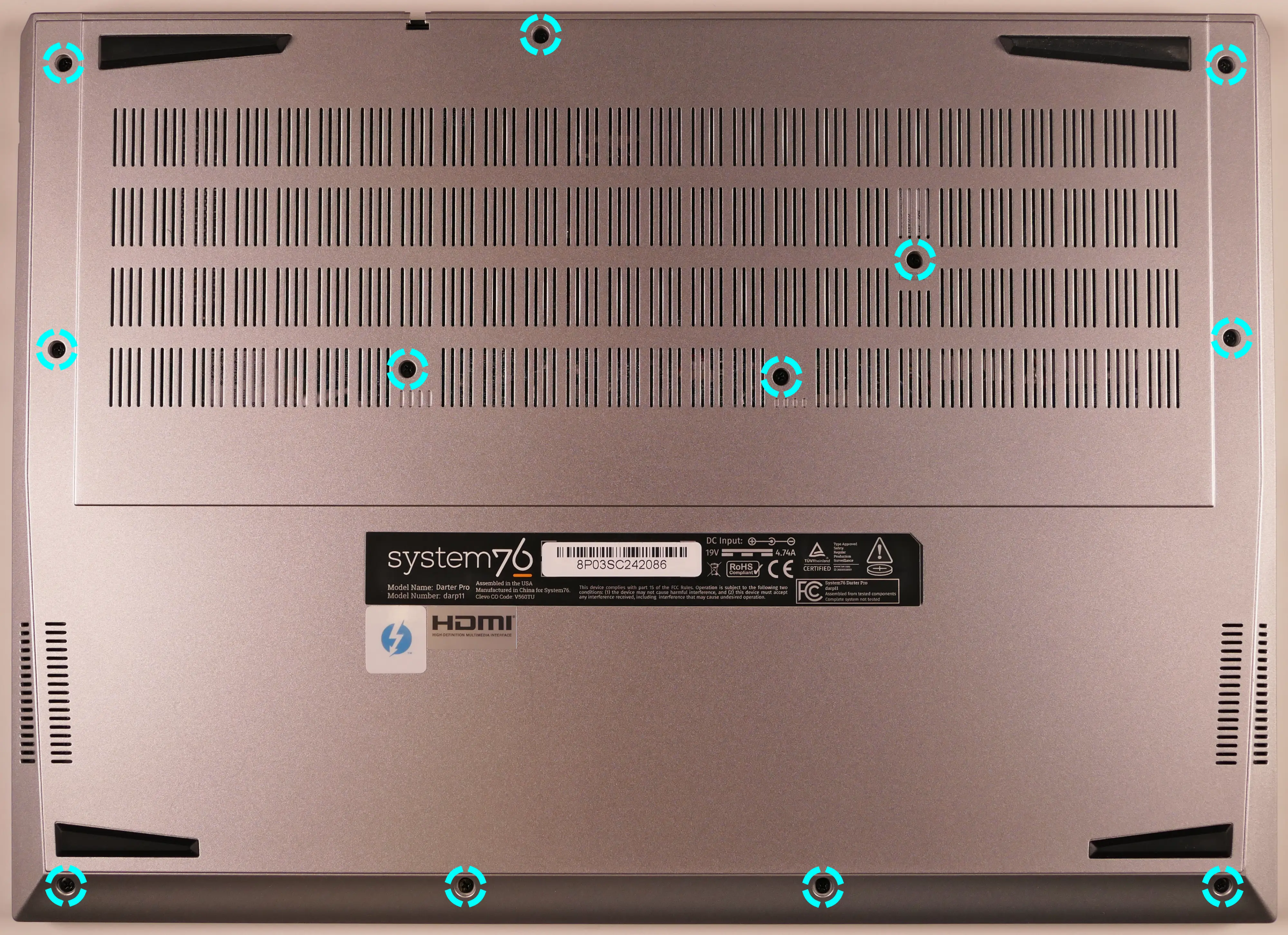
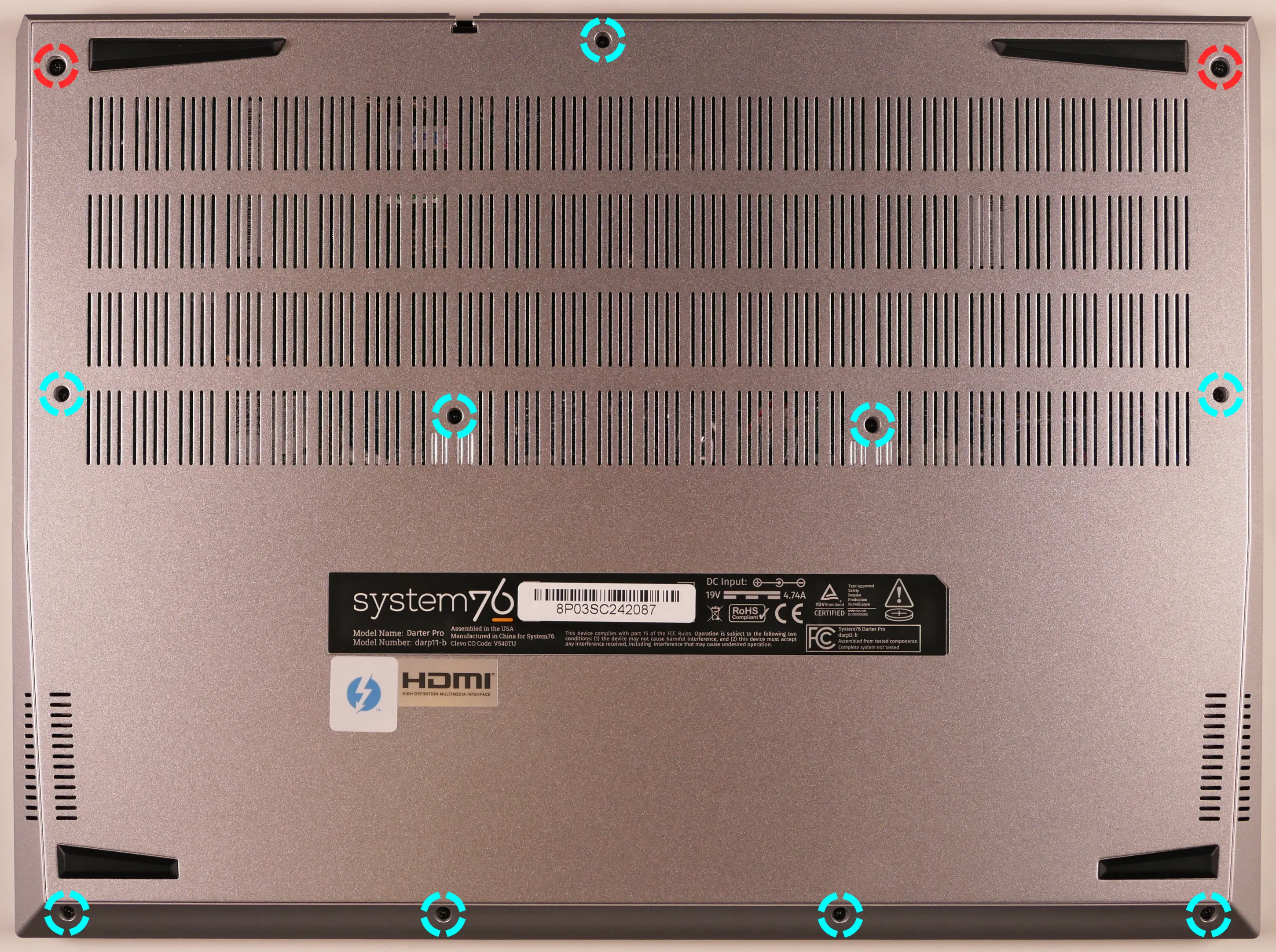
- Remove the bottom panel screws.
- On the 16" model (darp11), there are 13 screws of the same size.
- On the 14" model (darp11-b), there are 11 screws; the back corner screws are slightly larger.
- On the 16" model (darp11), there are 13 screws of the same size.
- Pull the bottom panel off, starting from the hinges in the back.

Replacing the RAM:
The Darter Pro 10 supports up to 96GB (2x48GB) of DDR5 SO-DIMMs running at 5600MHz. If you've purchased new RAM, need to replace your RAM, or are reseating your RAM, follow these steps.
Tools required: Cross-head (Phillips) screwdriver
Time estimate: 10 minutes
Difficulty: Easy ●
Steps to replace the RAM:
- Follow the steps above to remove the bottom cover.
- Press the small tabs on both sides of the RAM simultaneously. The RAM should spring up to an angle.

- Remove the RAM from the slot.
- Insert the new RAM (or reseat the existing RAM) by placing it into the keyed slot and pressing down until it clicks into place.
Replacing an M.2/NVMe SSD:
This model supports two M.2 SSDs. Both slots are size 2280 and support PCIe NVMe Generation 4.
Tools required: Cross-head (Phillips) screwdriver
Time estimate: 10 minutes
Difficulty: Easy ●
Steps to replace the M.2 drive:
- Follow the steps above to remove the bottom cover.
- Unscrew the retainer screw opposite the M.2 slot.
- SSD-1 is closest to the RAM (pictured on the top.)
- SSD-2 is closest to the battery (on the bottom.)

- Remove the existing M.2 drive by pulling it out of the slot.
- The SSD-1 slot allows lifting the drive up at an angle before removing (or re-inserting) it.
- The SSD-2 slot requires sliding the drive out of (or into) the slot parallel to the motherboard.
- Insert the new M.2 drive into the slot and hold it in place.
- Replace the retainer screw.
- If a square thermal pad was present on the old drive, transfer it to the new drive.
- If you are using a slot for the first time, you can optionally place a rectangle thermal pad adjacent to the SSD slot on the bottom panel. Peel off the blue and clear plastic backings from either side of the thermal pad before applying it.
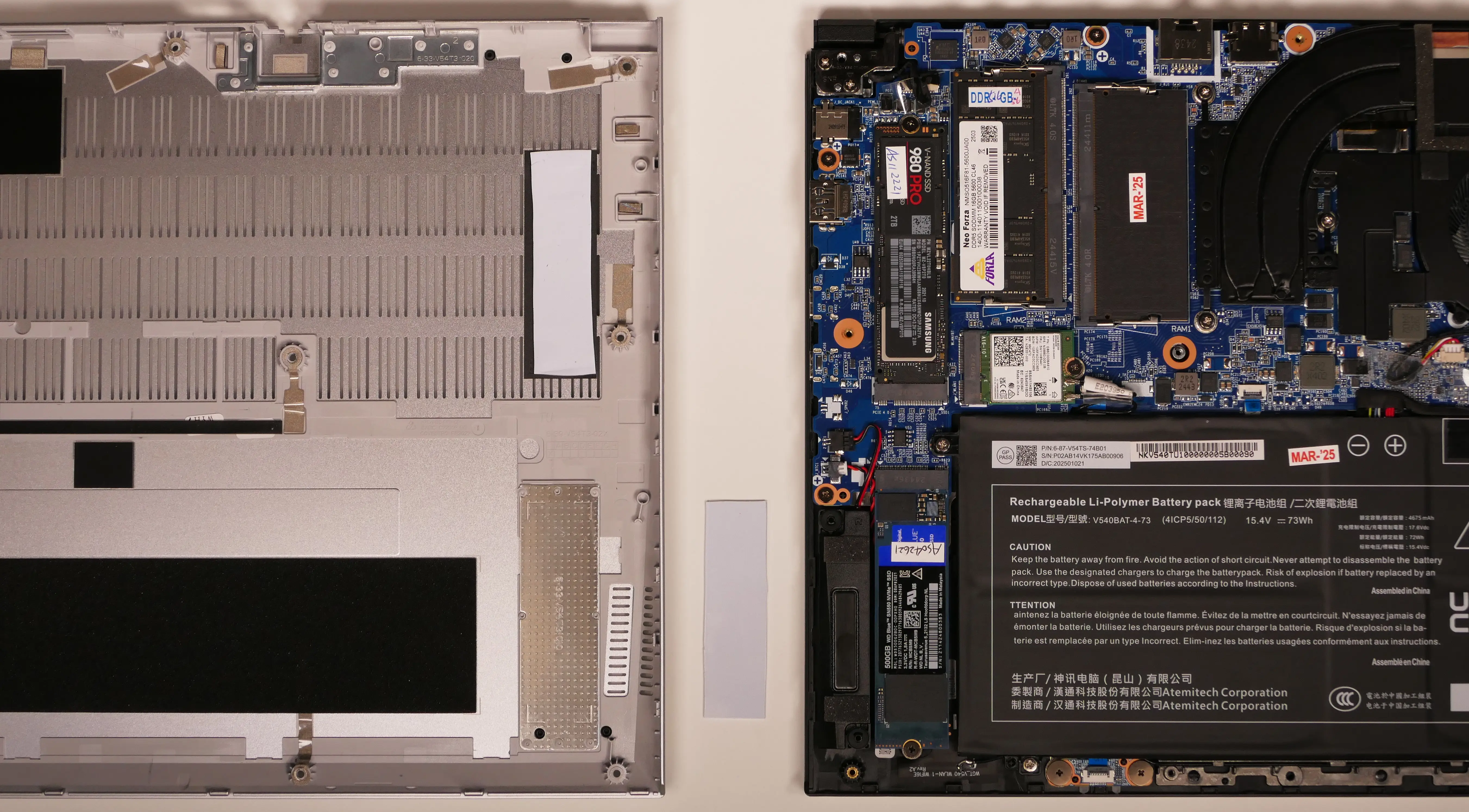
- If you are using a slot for the first time, you can optionally place a rectangle thermal pad adjacent to the SSD slot on the bottom panel. Peel off the blue and clear plastic backings from either side of the thermal pad before applying it.
Replacing the wireless card:
Your Darter Pro's WiFi and Bluetooth are both handled by the same module. It is a standard M.2 2230 slot with PCIe and USB interfaces (E-key).
Part numbers:
- The standard wireless card is an Intel
BE200.
Tools required: Cross-head (Phillips) screwdriver
Time estimate: 12 minutes
Difficulty: Medium ●
Steps to replace the WiFi/Bluetooth module:
- Follow the steps above to remove the bottom cover.
- Locate the wireless module. Remove any clear tape that is securing the wires.
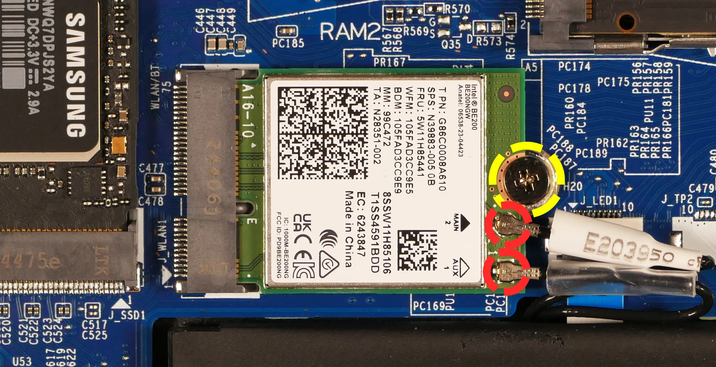
- Gently remove the two antennas (highlighted red above) by pulling them up and away from the wireless card.
- Remove the retaining screw opposite the M.2 slot, highlighted yellow above.
- The wireless card will pop up at an angle. Remove the card from the M.2 slot.
- Insert the new wireless card into the M.2 slot at an angle.
- Replace the retaining screw.
- Attach the two antennas by aligning the circular fittings and pressing onto the wireless card. The connectors will snap into place. Use caution when attaching the connectors; the pins can bend, break, or snap.
Replacing the CMOS battery:
The CMOS battery supplies power to the system's CMOS chip. UEFI settings and the computer's hardware clock are stored on the CMOS. If your system doesn't boot, you can reset the CMOS to force a low-level hardware reset. If your clock is constantly resetting, it's likely your CMOS battery needs to be replaced.
Warning (ingestion hazard): Keep batteries out of reach of children. Death or serious injury can occur if ingested. If a battery is suspected to be swallowed or inserted inside any part of the body, seek immediate medical attention. In the US, you can also call the National Battery Ingestion Hotline for guidance: 1 (800) 498-8666
Part numbers:
- The CMOS battery is a standard 3V KTS CR2032W battery.
Tools required: Cross-head (Phillips) screwdriver
Time estimate: 12 minutes
Difficulty: Easy ●
Steps to replace the CMOS battery:
- Follow the steps above to remove the bottom cover.
- If you are replacing the CMOS battery, remove SSD-2 to expose the CMOS battery, then pull it away from the adhesive holding it to the case.
- Unplug the white connector attaching the CMOS battery to the motherboard (highlighted green below).

- To clear the CMOS, disconnect the main battery, open the lid of the machine, and hold down the power button for at least 15 seconds to discharge any residual energy in the system.
- Re-connect the CMOS battery and the main battery, and replace the SSD and bottom panel.
- Power up the machine. The system may power itself off and on after initial boot; this is normal behavior when the CMOS has been reset.
Replacing the cooling system:
The Darter Pro 10 has a dual-fan heatsink assembly. If a fan becomes noisy and cleaning it out doesn't fix the issue, you may need a new fan. Contact support to start a warranty claim or parts purchase.
Depending on your climate and the age of the machine, it may be necessary to apply new thermal paste between the CPU and the heatsink. Thermal paste helps facilitate effective heat transfer between the CPU and the cooling equipment. These instructions can also be used in the unlikely event your heatsink needs to be replaced.
Part numbers:
- 16" model (darp11):
- Heatsink assembly:
6-31-V56TN-102, also known as the FCNMSS9 4BE 0DE. - Inner fan:
FSMF DFS5L22H15B853 EP(DC 5V 0.8A) - Outer fan:
FSMD DFS5L22H05B853 EP(DC 5V 0.8A)
- Heatsink assembly:
- 14" model (darp11-b):
- Heatsink assembly:
6-31-V54TN-102, also known as the FCNMSS8 4B8 464. - Inner fan:
FSMC DFS5L22H15B851 EP(DC 5V 0.8A) - Outer fan:
FSMB DFS5L22H05B851 EP(DC 5V 0.8A)
- Heatsink assembly:
Tools required: Cross-head (Phillips) screwdriver, thermal paste
Time estimate: 20 minutes
Difficulty: High ●
Steps to replace the fan/heatsink/thermal paste:
- Follow the steps above to remove the bottom cover.
- Remove any clear tape that is securing the fan wires.
- Unplug the two fan connectors, highlighted yellow below.
- This can alternatively be done after the fan/heatsink assembly is removed.

- Remove the five heatsink/fan screws in the order of the stamped numbers, starting with #1.
- The black fan screws (#1 and #2) are held captive and will not fully come out of the fan/heatsink assembly.
- Do not remove the smaller black screws holding the fan cover onto the fans.
- Remove the fan and heatsink from the system, being careful not to bend the heatsink pipe. It may take some pressure to break the seal of the thermal paste.
- Using a paper towel, remove the existing thermal paste. You may also use a small amount of rubbing alcohol if the old paste is dried or difficult to remove.

- After cleaning the CPU and heatsink, apply a small line of thermal paste directly onto the CPU chip.

- Carefully replace the heatsink.
- Replace the seven heatsink/fan screws in order, starting with #1, then #2, and so on until #7.
Replacing the speakers:
The system has two bottom-firing speakers, which can be replaced individually.
Part numbers:
- 16" model (darp11):
- Left speaker:
- Model number:
V560TU-L - Part number:
6-23-5V56T-0L1
- Model number:
- Right speaker:
- Model number:
V560TU-R - Part number:
6-23-5V56T-0R1
- Model number:
- Left speaker:
- 14" model (darp11-b):
- Left speaker:
- Model number:
V540TU-L - Part number:
6-23-5V54T-0L1
- Model number:
- Right speaker:
- Model number:
V540TU-R - Part number:
6-23-5V54T-0R0
- Model number:
- Left speaker:
Tools required: Cross-head (Phillips) screwdriver
Time estimate: 10 minutes
Difficulty: Medium ●
Steps to replace the speakers:
- Follow the steps above to remove the bottom cover.
- Remove any clear tape securing the speaker wires.
- Disconnect the black speaker connectors from the motherboard.
- This can alternatively be done after freeing the speakers.
- Remove the speakers from the chassis.
- For the 16" model (darp11), unscrew the speakers. To help free the left speaker, remove the main battery.
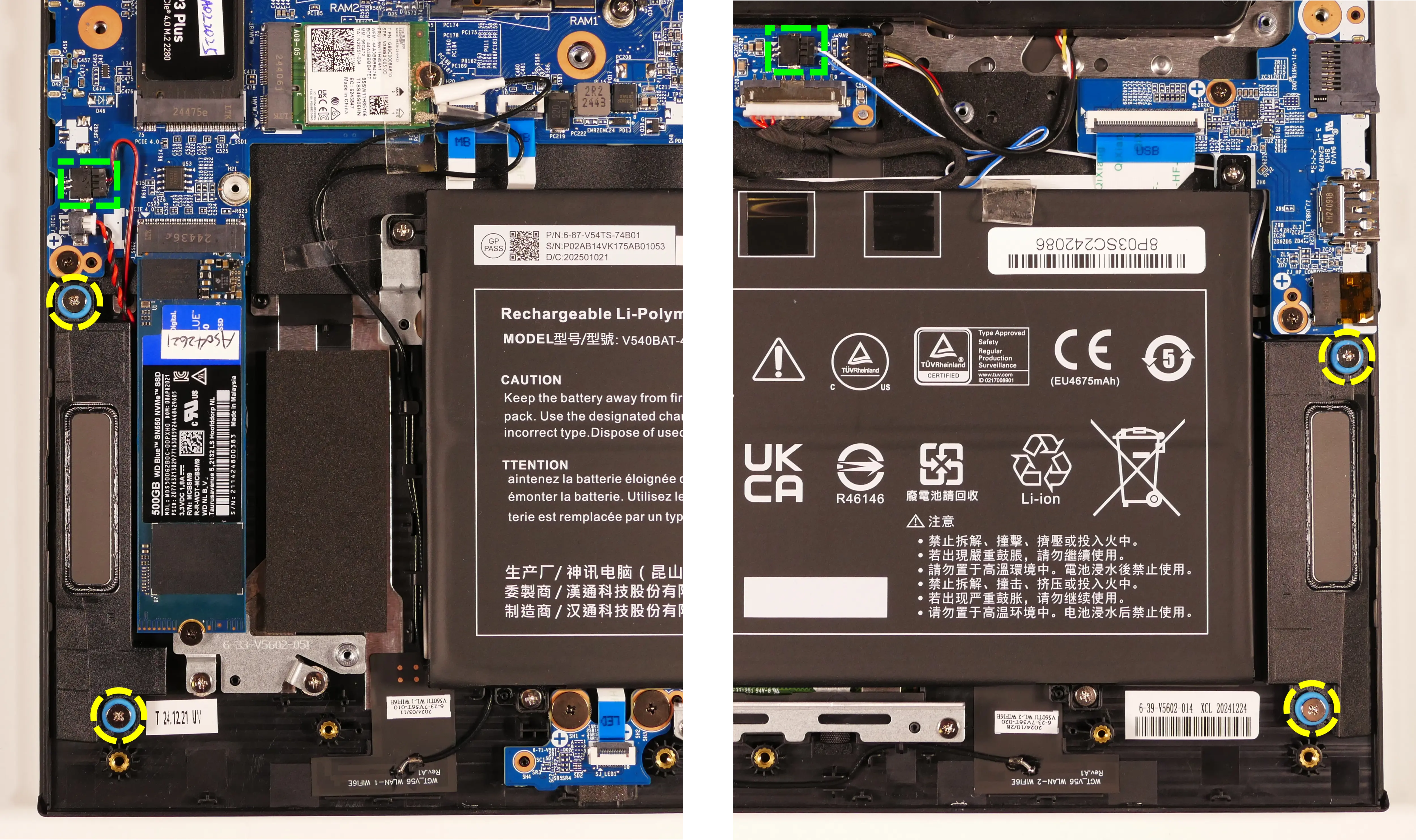
- For the 14" model (darp11-b), lift the speakers up and off of the plastic posts.
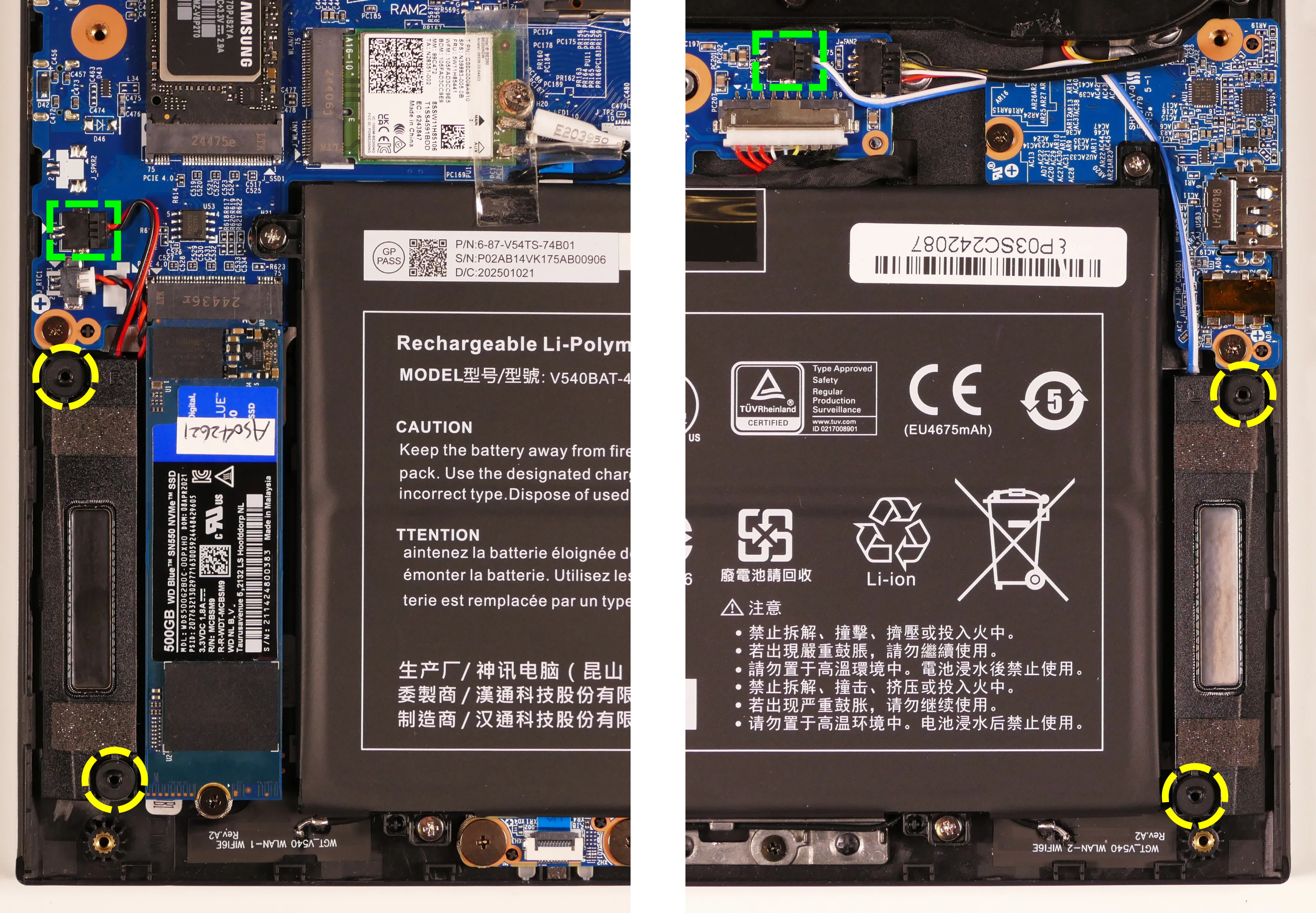
- For the 16" model (darp11), unscrew the speakers. To help free the left speaker, remove the main battery.
- Slide the new speakers onto the plastic posts and connect them to the motherboard.
- The left speaker's wire can be run through the channel in the chassis before or after plugging it in.
Replacing the keyboard:
The keyboard can be replaced if its switches or electronics have been damaged.
Part numbers:
- 16" (darp11) keyboard:
6-23-RV56T-011 - 14" (darp11-b) keyboard:
6-23-RL245-010-1 - Keyboards shipped by System76 include a custom-printed Super key.
Tools required: Cross-head (Phillips) screwdriver
Time estimate: 10 minutes
Difficulty: Medium ●
Steps to replace the keyboard:
- Place the machine lid-side down.
- Use a soft surface (such as a towel) to avoid scratches.
- Remove the keyboard screws (highlighted yellow below).
- On the 16" model (darp11), there is one keyboard screw.
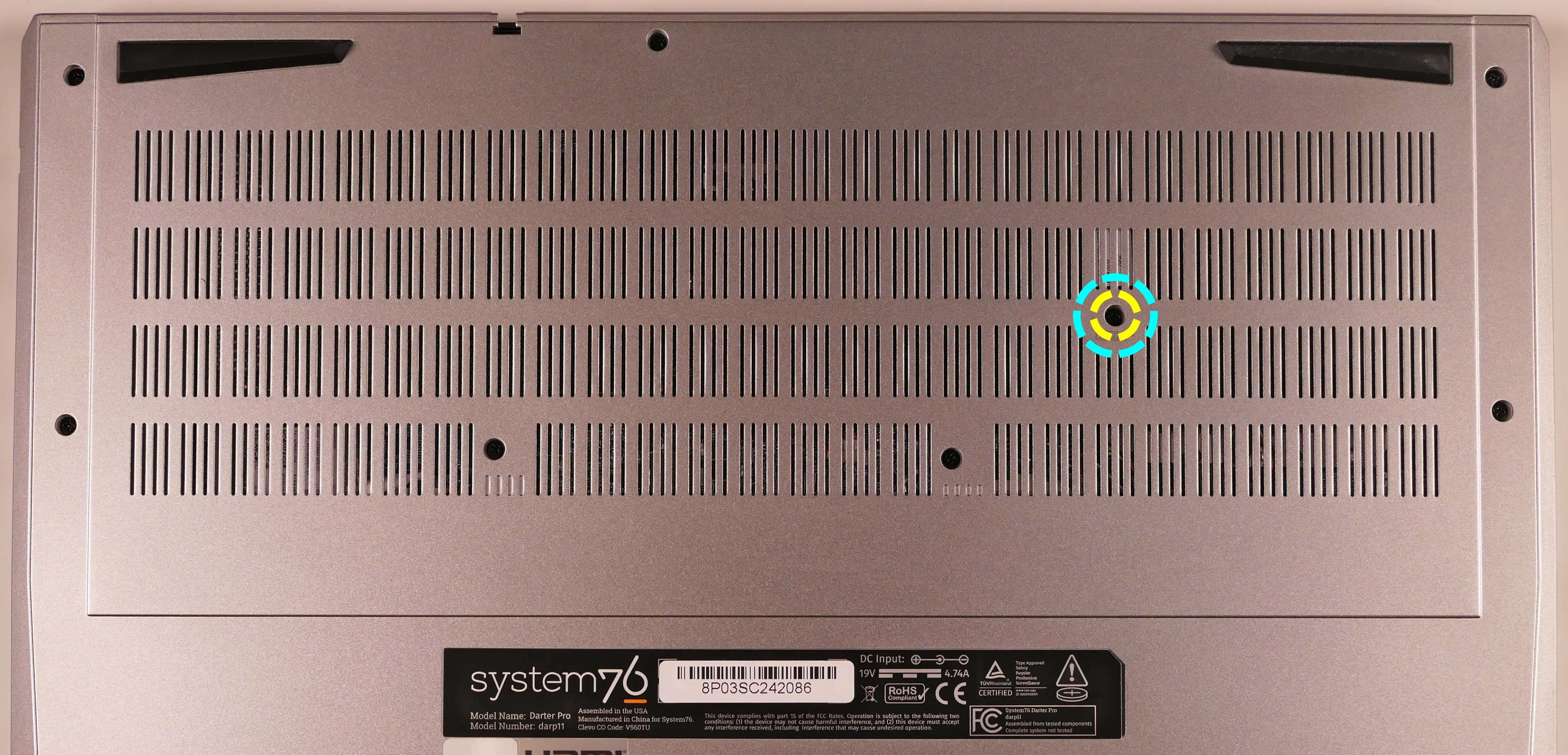
- On the 14" model (darp11-b), there are two keyboard screws.
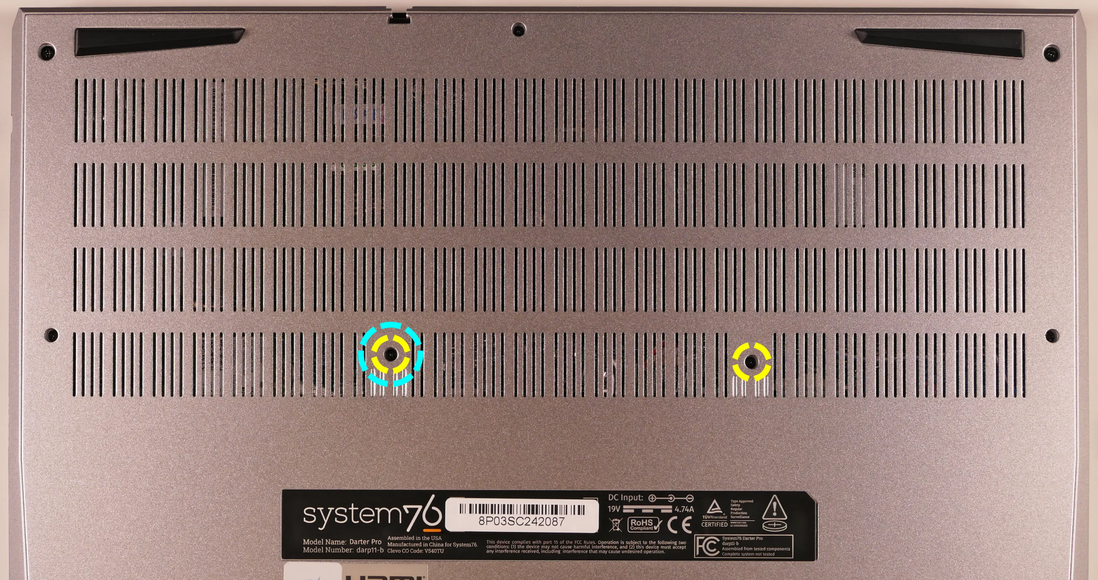
- On the 16" model (darp11), there is one keyboard screw.
- For the 16" model (darp11) only, you can optionally remove the bottom panel, remove the heatsink, and slowly pull the tabs highlighted below to remove the two keyboard adhesive strips.
- If you skip this step, pull the keyboard out slowly to avoid tearing its material on the adhesive, and be careful not to yank the keyboard away from the chassis before the ribbon cables have been detatched.
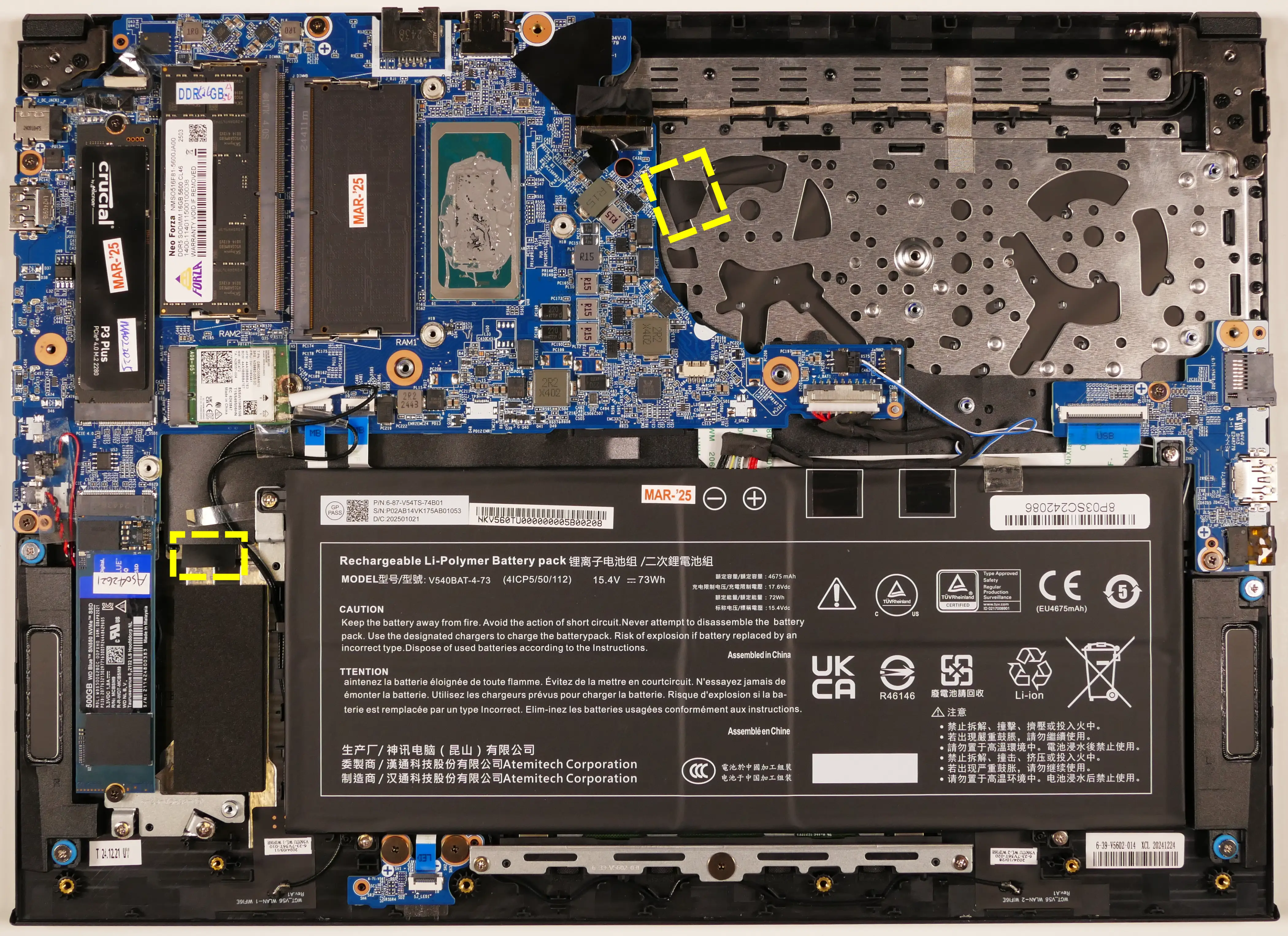
- If you skip this step, pull the keyboard out slowly to avoid tearing its material on the adhesive, and be careful not to yank the keyboard away from the chassis before the ribbon cables have been detatched.
- Open the lid slightly and place the machine on its side.
- Push the screwdriver into the keyboard push point (highlighted cyan above) until the keyboard pops out.

- Set the machine back down and raise the keyboard away from the chassis. The larger ribbon cable is for the keyboard, while the smaller ribbon cable is for the keyboard backlight.
- On the 16" model (darp11), the keyboard backlight cable is to the right of the main cable.
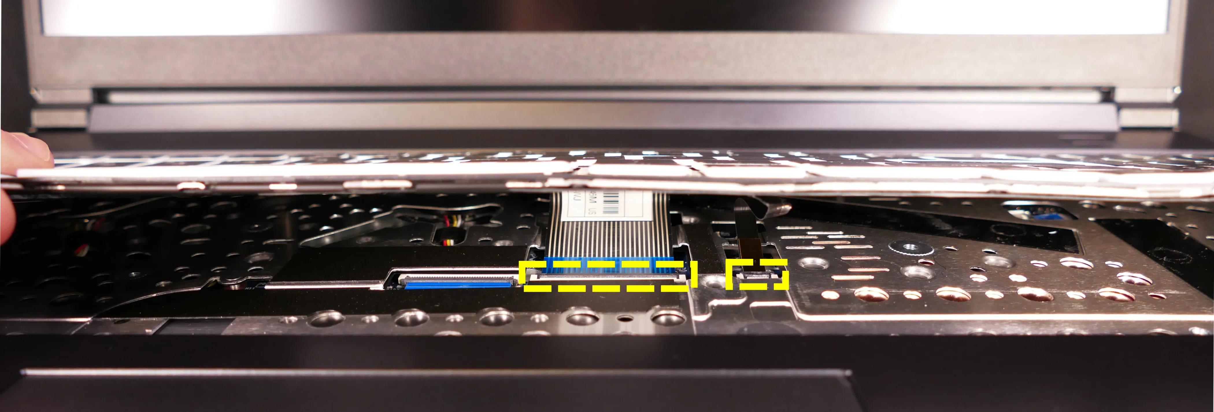
- On the 14" model (darp11-b), the keyboard backlight cable is to the left of the main cable.
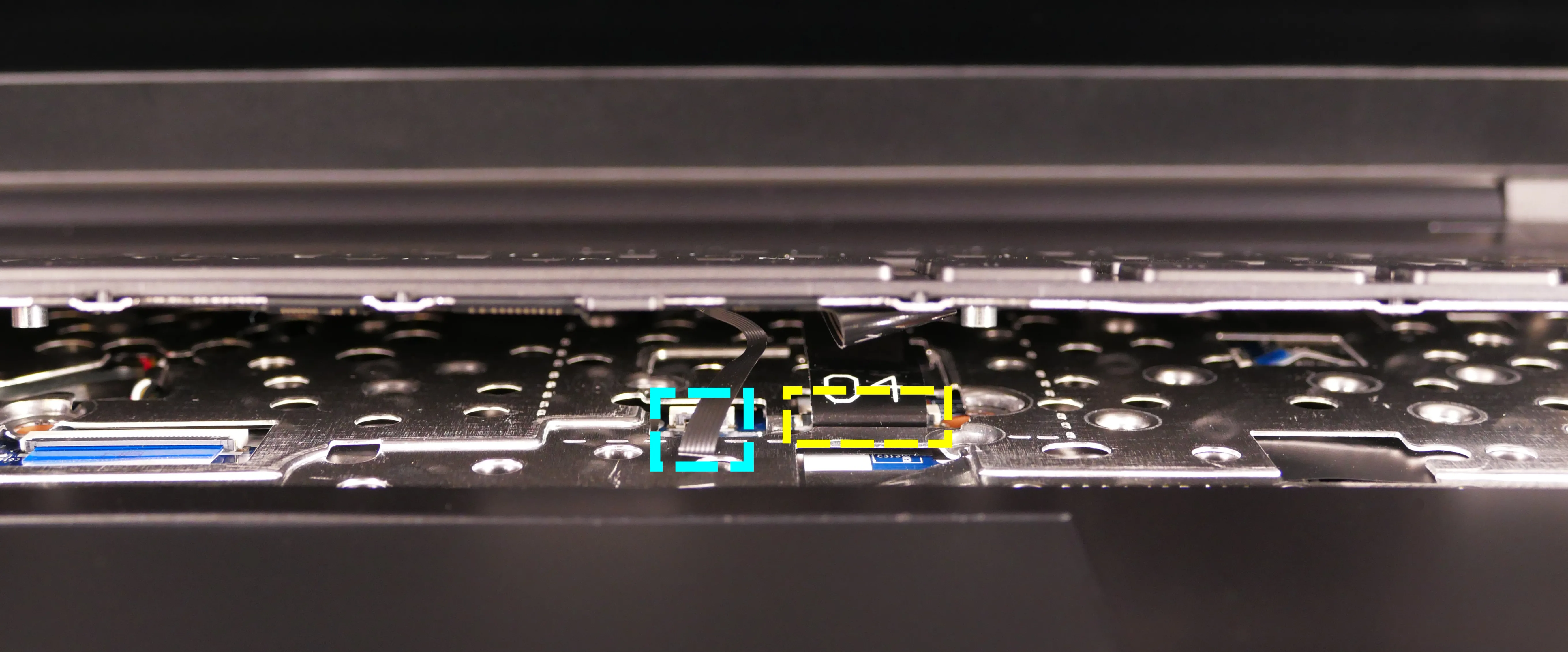
- On the 16" model (darp11), the keyboard backlight cable is to the right of the main cable.
- Flip the black latches upwards to free the ribbon cables.
- Pull the ribbon cables out of the connectors.
- Remove the keyboard and replace it with the new one.
- Carefully slide both ribbon cables into their connectors.
- Flip the black latches back into place to secure the ribbon cables.
- For the 16" model (darp11) only, optionally replace the keyboard adhesive strips (if they were removed earlier).
- The keyboard can be installed without adhesive strips if they're no longer usable.
- Place the keyboard back into position, starting with the tabs on the bottom edge.
- Secure the rest of the keyboard by pressing down on each of its edges.
- Turn the machine lid-side down again and replace the two keyboard screws.
Replacing the battery:
The battery provides primary power whenever the system is unplugged.
Part numbers:
- The battery's model number is
V540BAT-4-73. - The battery's original part number is
6-87-V54TS-74B01. - Third-party battery sellers may list one or both of these numbers, and may offer other compatible part numbers with the same model number. You can also contact System76 to purchase a replacement battery.
Tools required: Cross-head (Phillips) screwdriver
Time estimate: 15 minutes
Difficulty: Easy ●
Steps to replace the battery:
- Follow the steps above to remove the bottom cover.
- Remove any clear tape holding other wires down to the battery.
- Unscrew the four screws holding the battery into the chassis.
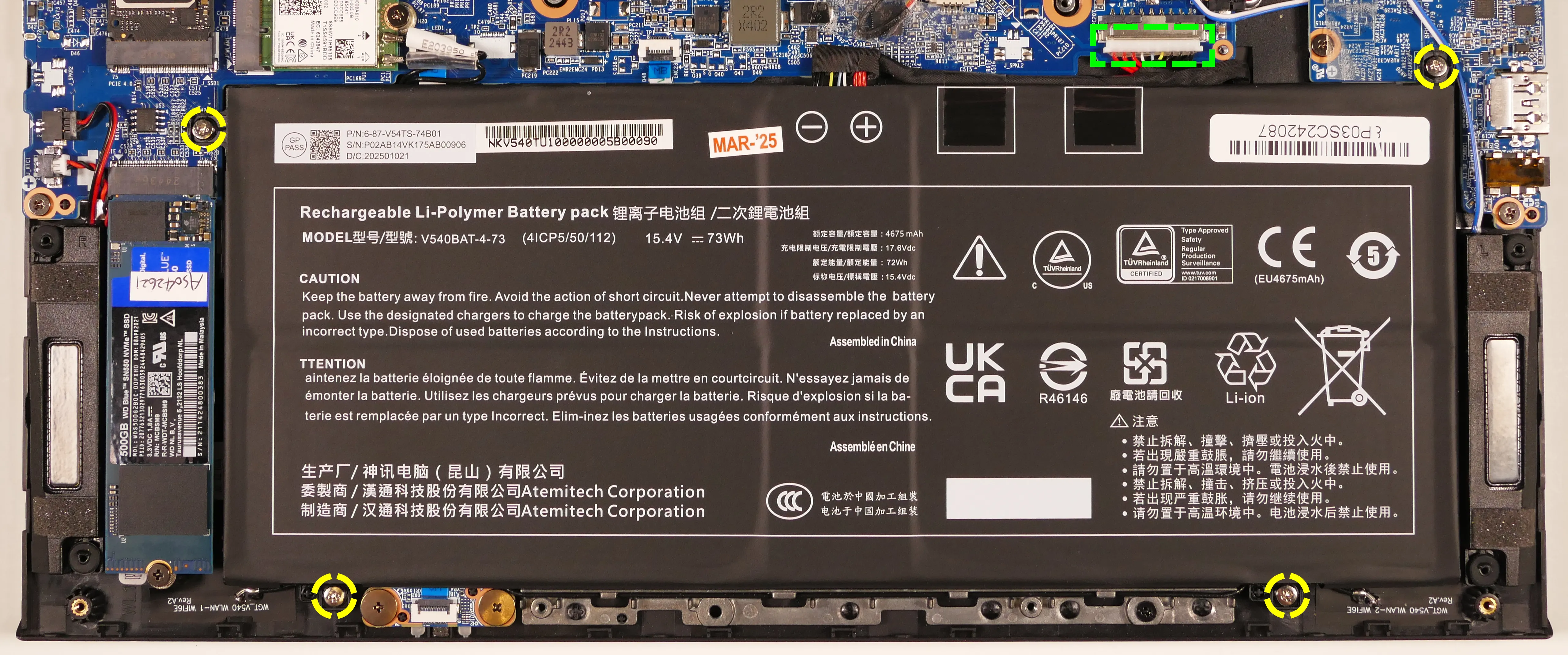
- Unplug the white connector that connects the battery to the motherboard.
- Remove and replace the battery.
Eland 1U (elan1-r3)

The System76 Eland 1U is a rack-mounted server. The R3 model code indicates the third revision based on an AMD platform. This model has the following specifications:
- Chassis (depending on configuration)
- CPU options
- Supports 1x AMD EPYC 9004-series processor
- Memory
- Up to 1536GB (24x64GB) ECC DDR4 @ 4800 MHz
- Storage
- RS12U model:
- 12 x 2.5" SATA/NVMe hot-swappable HDD/SSD bays
- RS4U model:
- 4 x 3.5" SATA/NVMe hot-swappable HDD/SSD bays
- RS12U model:
- Networking
- 2x 1GbE LAN ports (1 x Intel® I350-AM2)
- 1x 1GbE management LAN
- Expansion
- 1x PCIe 5.0 x16 slot (full-height, half-length)
- 1x PCIe 5.0 x16 slot (half-height, half-length)
- 1x PCIe 5.0 x8 slot (half-height, half-length)
- 1x OCP 3.0 5.0 x16 socket
- Front I/O
- 2x USB 3.2 Gen1
- 1x VGA port
- 1x Power Button/LED
- 1x Location Button/LED
- 1x Message LED
- 1x HDD LED
- 4x LAN LEDs
- 1-2: On-board LAN
- 3-4: OCP socket LAN
- Back I/O
- 2x USB 3.2 Gen1
- 1x VGA port
- 1x Management LAN
- 2x RJ45 (Ethernet)
- 1x Port80 LED (Q-Code)
- 1x Power Button/LED
- 1x Location Button/LED
- 1x Message LED
- Power Supply
- 2x 1600W redundant 80+ Titanium PSUs
- AC Input: 100-240 12-7A, 50-60Hz
- Dimensions
- 44.9cm × 84.25cm × 4.39cm
- Weight
- 14.16kg
Eland Pro 2U (elap2-r3)
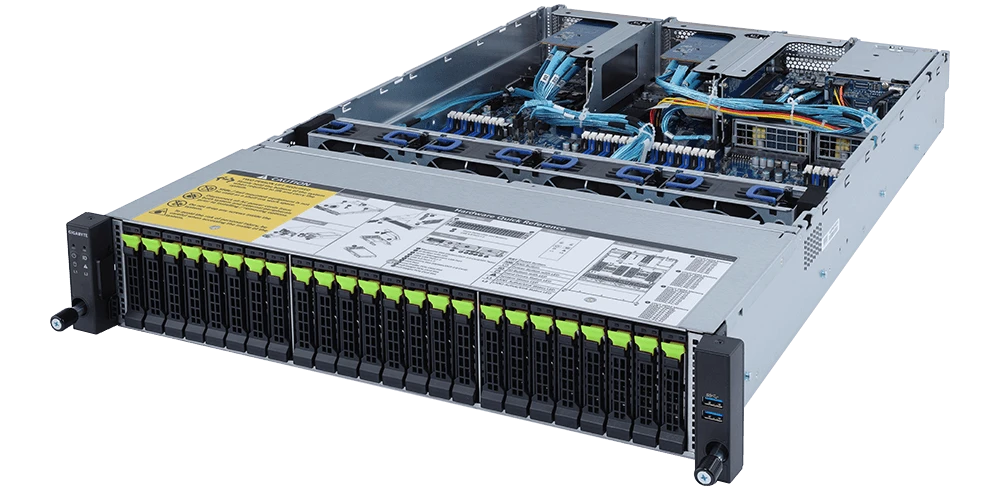
The System76 Eland Pro 2U is a rack-mounted server. The R3 model code indicates the third revision based on an AMD platform. This model has the following specifications:
- Chassis
- CPU options
- Supports 2x AMD EPYC 7003-series or 7002-series processors
- Memory
- Up to 8192GB (32x256GB) ECC DDR4 @ 3200 MHz
- Storage
- Front: 24x 2.5" U.2 NVMe Gen 4 hot-swappable HDD/SSD bays
- Back: 2x 2.5" SATA/SAS hot-swappable HDD/SSD bays
- Internal: 1x M.2 PCIe NVMe Gen 4 x4 slot
- CPU TDP limited to 225W if M.2 slot is occupied
- Networking
- 2x 1GbE LAN ports (1 x Intel I350-AM2)
- 1x 1GbE management LAN
- Expansion
- Riser Card 2015 (CPU 1):
- 1x PCIe Gen 4 x16 (full-height, half-length)
- Occupied by CNV3134 (4x NVMe adapter)
- 1x PCIe Gen 4 x16 (full-height, half-length)
- Riser Card CRS2033 (CPU 0):
- 1x PCIe Gen 4 x16 (full-height, half-length)
- 2x PCIe Gen 4 x8 (full-height, half-length)
- Occupied by 2x CNV3132 (2x NVMe adapter)
- Riser Card CRS2033 (CPU 1):
- 1x PCIe Gen 4 x16 (full-height, half-length)
- 2x PCIe Gen 4 x8 (full-height, half-length)
- Occupied by 2x CNV3132 (2x NVMe adapter)
- Riser Card 2015 (CPU 1):
- Front I/O
- 2x USB 3.0
- 1x Power button with LED
- 1x ID button with LED
- 1x Reset button
- 1x NMI button
- 1x System status LED
- 1x HDD activity LED
- 2x LAN activity LEDs
- Back I/O
- 2x USB 3.0
- 1x VGA
- 2x RJ45 (Ethernet)
- 1x Management LAN
- 1x ID button with LED
- Power Supply
- 2x 1600W redundant 80+ Platinum PSUs
- AC Input: 100-240V 12-10A, 50-60Hz
- Dimensions
- 43.8cm × 73.0cm × 8.7cm
- Weight
- 25.5kg
Galago Pro (galp7)
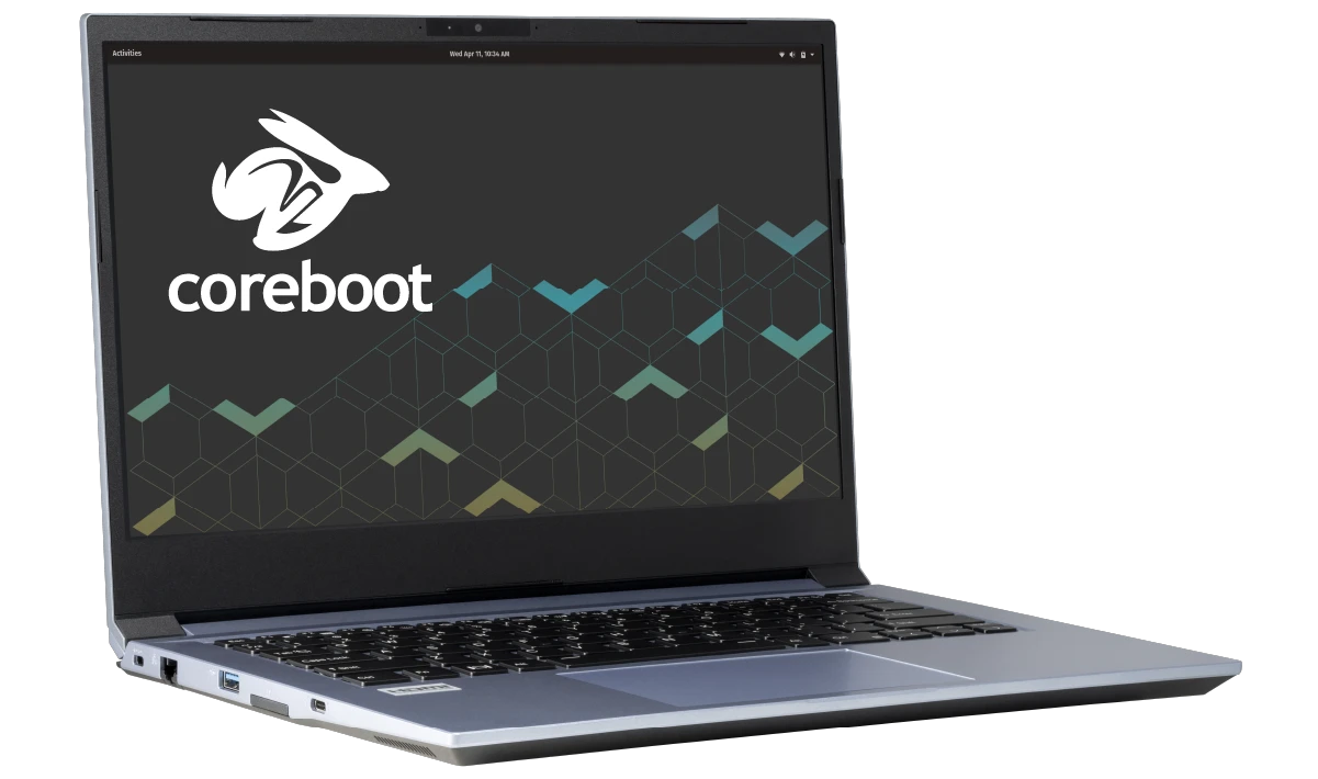
The System76 Galago Pro is a laptop with the following specifications:
- CPU
- Supports Intel 13th Generation (Raptor Lake-H) CPUs
- BIOS
- Macronix flash chip
- WSON-8 form factor
- Programmed with System76 Open Firmware
- Macronix flash chip
- EC
- ITE IT5570E
- Programmed with System76 EC
- Graphics
- GPU options:
- Intel Iris Xe Graphics
- eDP display: 14.1" 1920x1080@144Hz LCD
- LCD panel: Sharp LQ140M1JW49 (or equivalent)
- External video outputs:
- 1x HDMI 2.1
- 1x DisplayPort 1.4 over USB-C
- GPU options:
- Memory
- Up to 64GB (2x32GB) dual-channel DDR4 SO-DIMMs @ 3200 MHz
- Networking
- Gigabit Ethernet
- M.2 PCIe/CNVi WiFi/Bluetooth
- Intel Wi-Fi 6E AX210/AX211
- Bluetooth 5.3
- Intel Wi-Fi 6E AX210/AX211
- Power
- 90W (19V, 4.74A) DC-in port
- Barrel size: 5.5mm (outer), 2.5mm (inner)
- Included AC adapter: Chicony A16-090P1A
- AC power cord type: IEC C5
- USB-C charging compatible with 90W+ charger
- 53Wh 4-cell Lithium-Ion battery
- Model number: NV40BAT-4-53
- 90W (19V, 4.74A) DC-in port
- Sound
- Internal speakers & microphone
- 3.5mm headphone/microphone combo jack
- HDMI, USB-C DisplayPort audio
- Storage
- 1x M.2 (PCIe NVMe Gen 4) SSD
- SD card reader
- USB
- 1x USB Type-C with Thunderbolt 4
- Supports DisplayPort over USB-C
- Supports USB-C charging (USB-PD)
- 1x USB 3.2 (Gen 2) Type-C
- 2x USB 3.2 (Gen 1) Type-A
- 1x USB Type-C with Thunderbolt 4
- Dimensions
- 32.49cm x 22.5cm x 1.82cm, 1.45kg
Galago Pro (External Overview)
Left side overview:

Right side overview:

Front side overview:

Back side overview:

Keyboard & touchpad overview:
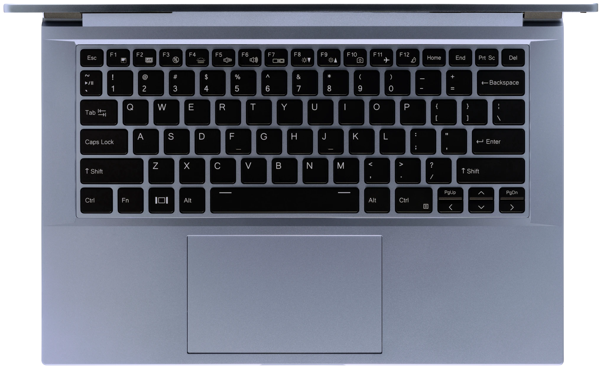
Materials:
| Part | Material | Part Number |
|---|---|---|
| LCD back cover (lid) | Aluminum | 6-39-NV411-023 |
| LCD front cover (bezel) | Plastic | 6-40-NV401-011 |
| Top case (palm rests/port covers) | Plastic | 6-78-NV41RZ02-010 |
| Bottom panel | Plastic | 6-39-NV4K3-011 |
LED indicators
The Galago Pro has the following LED indicators:
| Icon | Color | Description |
|---|---|---|
 | Orange | Powered off, DC power plugged in |
| Green | Powered on | |
| Blinking green | Sleeping (suspended) | |
 | Orange | Battery charging |
| Green | Battery fully charged | |
| Blinking orange | Battery critically low |
Keyboard Shortcuts
The Galago Pro has the following actions available using the Fn and Function keys:
| Key | Shortcut | Action |
|---|---|---|
 | Fn+F1 | Toggle trackpad |
 | Fn+F2 | Toggle built-in LCD |
 | Fn+F3 | Mute |
 | Fn+F4 | Cycle keyboard backlight brightness |
 | Fn+F5 | Volume down |
 | Fn+F6 | Volume up |
 | Fn+F7 | Toggle displays |
 | Fn+F8 | Screen brightness down |
 | Fn+F9 | Screen brightness up |
 | Fn+F10 | Toggle webcam |
 | Fn+F11 | Toggle airplane mode |
 | Fn+F12 | Suspend |
 | Fn+` | Play/Pause |
| 1 | Fn+1 | Toggle fan between max/automatic |
Galago Pro (Internal Overview)
Bottom components and connectors:

- RAM slots are highlighted in purple
- M.2 SSD is highlighted in maroon
- Wireless card is highlighted in yellow
- CMOS battery connector is highlighted in pink
- Webcam/microphone connector is highlighted in cyan
- BIOS flash chip (U43) is highlighted in black
- Fan connectors are highlighted in red
- Speaker connectors are highlighted in dark green
- Main battery connector is highlighted in orange
- Touchpad connector is highlighted in white
- LCD panel connector is highlighted in light green
Under-keyboard components and connectors:

- Keyboard connector is highlighted in green
- Keyboard backlight connector is highlighted in red
- EC chip is highlighted in cyan
- ITE IT5570E-128
Galago Pro (Parts & Repairs)
Many components in your Galago Pro can be upgraded or replaced as necessary. Follow these step-by-step guides for instructions:
- Removing the bottom cover
- Removing the battery
- Replacing the RAM
- Replacing an M.2/NVMe SSD
- Replacing the WiFi/Bluetooth module
- Replacing the CMOS battery
- Replacing the speakers
- Replacing the fans/heatsink/thermal paste
- Replacing the keyboard
Removing the bottom cover:
Removing the cover is required to access the internal components. Prior to removing the cover, ensure the AC power is unplugged and all peripherals (including SD cards and USB drives) are unplugged or removed from the system.
Tools required: Cross-head (Phillips) screwdriver
Time estimate: 5 minutes
Difficulty: Easy ●
Steps to remove the bottom cover:
- Place the machine lid-side down.
- Use a soft surface (such as a towel) to avoid scratches.
- Remove the 14 bottom panel screws.
- The two hinge corner screws (highlighted red below) are slightly thicker than the rest.

- Pull the bottom panel off, starting from the hinges and vents in the back.
Removing the battery:
The battery provides primary power whenever the system is unplugged.
The model number for the Galago Pro 7's battery is NV40BAT-4-53, and the original part number is 6-87-NV4PS-54B01. Third-party battery sellers may list one or both of these numbers, and may offer other compatible part numbers with the same model number. You can also contact System76 to purchase a replacement battery.
Tools required: Cross-head (Phillips) screwdriver
Time estimate: 10 minutes
Difficulty: Easy ●
Steps to remove the battery:
- Follow the steps above to remove the bottom cover.
- Remove the five battery screws, highlighted green below.

- Unplug the battery connector (highlighted yellow above) and lift the battery out of the chassis.
Replacing the RAM:
The Galago Pro 7 supports up to 64GB (2x32GB) of DDR4 SO-DIMMs running at 3200MHz. If you've purchased new RAM, need to replace your RAM, or are reseating your RAM, follow these steps.
Tools required: Cross-head (Phillips) screwdriver
Time estimate: 10 minutes
Difficulty: Easy ●
Steps to replace the RAM:
- Follow the steps above to remove the bottom cover.
- Press the small tabs on both sides of the RAM simultaneously. The RAM should spring up to an angle.

- Remove the RAM from the slot.
- Insert the new RAM (or reseat the existing RAM) by placing it in the keyed slot and pressing down until it clicks into place.
Replacing an M.2/NVMe SSD:
This model supports one M.2 SSD of size 2280 with a PCIe NVMe Generation 4 interface.
Tools required: Cross-head (Phillips) screwdriver
Time estimate: 10 minutes
Difficulty: Easy ●
Steps to replace the M.2 drive:
- Follow the steps above to remove the bottom cover.
- Unscrew the retainer screw opposite the M.2 slot.
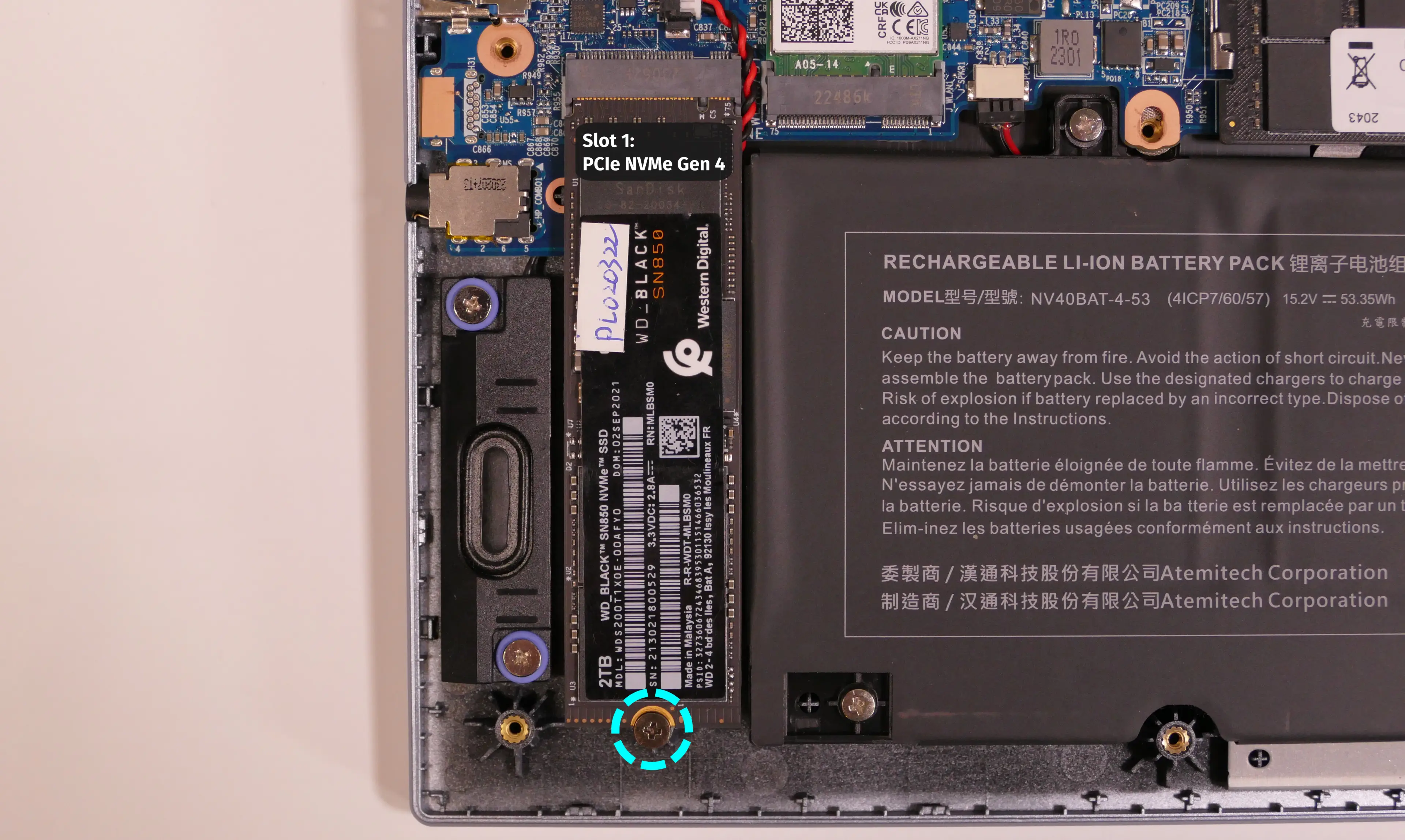
- Remove the existing M.2 drive by pulling it out of the slot.
- Insert the new M.2 drive into the slot and hold it in place.
- Replace the retainer screw.
Replacing the wireless card:
Your Galago Pro's WiFi and Bluetooth are both handled by the same module. It is a standard M.2 2230 slot with PCIe and USB interfaces (E-key).
Tools required: Cross-head (Phillips) screwdriver
Time estimate: 12 minutes
Difficulty: Medium ●
Steps to replace the WiFi/Bluetooth module:
- Follow the steps above to remove the bottom cover.
- Locate the wireless module. Remove any clear tape that is securing the wires.

- Gently remove the two antennas (highlighted red above) by pulling them up and away from the wireless card.
- Remove the retaining screw opposite the M.2 slot, highlighted yellow above.
- The wireless card will pop up at an angle. Remove the card from the M.2 slot.
- Insert the new wireless card into the M.2 slot at an angle.
- Replace the retaining screw.
- Attach the two antennas by aligning the circular fittings and pressing onto the wireless card. The connectors will snap into place. Use caution when attaching the connectors; the pins can bend, break, or snap.
Replacing the CMOS battery:
The CMOS battery supplies power to the system's CMOS chip. UEFI settings and the computer's hardware clock are stored on the CMOS. If your system doesn't boot, you can reset the CMOS to force a low-level hardware reset. If your clock is constantly resetting, it's likely your CMOS battery needs to be replaced.
Warning (ingestion hazard): Keep batteries out of reach of children. Death or serious injury can occur if ingested. If a battery is suspected to be swallowed or inserted inside any part of the body, seek immediate medical attention. In the US, you can also call the National Battery Ingestion Hotline for guidance: 1 (800) 498-8666
Tools required: Cross-head (Phillips) screwdriver
Time estimate: 15 minutes
Difficulty: Medium ●
Steps to replace the CMOS battery:
- Follow the steps above to remove the bottom cover.
- Follow the steps above to remove the M.2 drive, then pull the battery away from the adhesive holding it to the case.
- If you are not replacing the CMOS battery, this step is optional, but will make it easier to unplug the CMOS battery connector.

- Unplug the white connector attaching the CMOS battery to the motherboard (highlighted green above.)
- To clear the CMOS, disconnect the main battery, open the lid of the machine, and hold down the power button for at least 15 seconds to discharge any residual energy in the system.
- Re-connect the CMOS battery and main battery, and replace the M.2 drive and bottom panel.
- Power up the machine. The system may power itself off and on after initial boot; this is normal behavior when the CMOS has been reset.
Replacing the speakers:
The system has two bottom-firing speakers, which can be removed and replaced individually.
Tools required: Cross-head (Phillips) screwdriver
Time estimate: 15 minutes
Difficulty: Easy ●
Steps to replace the speakers:
- Follow the steps above to remove the bottom cover. For the right speaker, also remove the battery and remove the SSD.
- Unscrew the speaker screws.
- Each speaker has two screws, which are set inside of rubber rings to reduce vibration.

- Disconnect the speaker wire from the motherboard and lift the speaker out of the machine.
- The speaker wire may be partially routed behind other components or tape; be careful when removing it.
- Place the new speaker in the machine, plug in the connector, replace the screws, and reinstall the SSD and battery (if necessary) and bottom panel.
Replacing the cooling system:
The Galago Pro 7 has a single heatsink with two fans for the CPU and integrated GPU. One fan is attached to the heatsink, while the other can be replaced independently.
If a fan becomes noisy and cleaning it out doesn't fix the issue, you may need a new fan. Contact support to start a warranty claim or parts purchase.
Depending on your climate and the age of the machine, it may be necessary to apply new thermal paste between the CPU and the heatsink. Thermal paste helps facilitate effective heat transfer between the CPU and the cooling equipment. These instructions can also be used in the unlikely event that your heatsink needs to be replaced.
Tools required: Cross-head (Phillips) screwdriver, thermal paste
Time estimate: 20 minutes
Difficulty: High ●
Steps to replace the additional fan:
- Follow the steps above to remove the bottom cover.
- Remove any clear tape that is securing the fan wire.
- Unplug the white fan connector for the additional fan, highlighted green below.
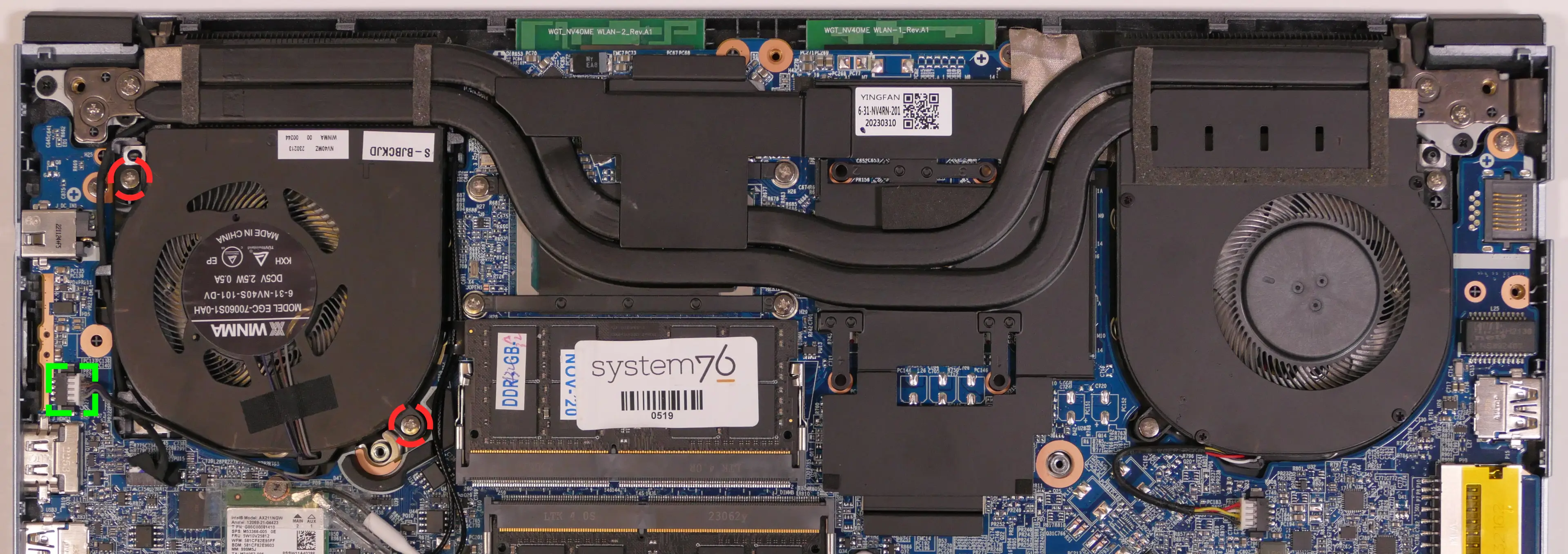
- Remove the two fan screws, highlighted red above.
- Replace the fan, screw in the two fan screws, and plug the white fan connector into the system.
Steps to replace the heatsink/thermal paste:
- Follow the steps above to remove the bottom cover and remove the additional fan.
- Removing the additional fan is optional, but is recommended to ensure the fan properly overlaps the heatsink's air guide after reinstallation.
- Unplug the remaining fan connector, highlighted green below.
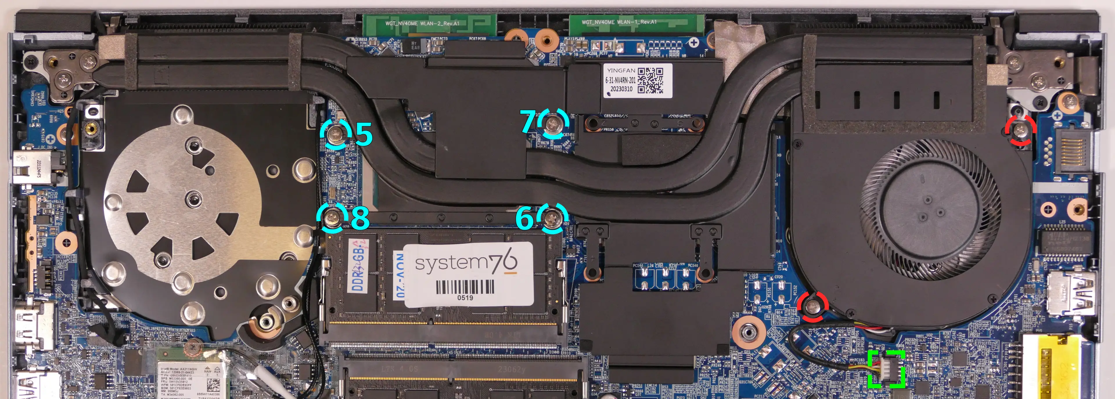
- Remove the two fan screws for the remaining fan, highlighted red above.
- Remove the four heatsink screws (highlighted cyan above) in order, starting with #5, then #6, and continuing until #8.
- Screws #1-4 are for the dedicated GPU portion of the heatsink, and are not installed on the Galago Pro 7.
- Remove the heatsink from the system, being careful not to bend the heatsink pipes. It may take some pressure to break the seal of the thermal paste.
- Using a paper towel, remove the existing thermal paste. You may also use a small amount of rubbing alcohol if the old paste is dried or difficult to remove.

- After cleaning the CPU and heatsink, apply a small line of thermal paste directly onto each die of the CPU chip.

- Carefully replace the heatsink.
- Replace the four heatsink screws, starting with #5, then #6, and continuing until #8.
- Screw in the attached fan and plug its connector back into the motherboard.
- Replace the additional fan and bottom panel.
Replacing the keyboard:
The keyboard can be replaced using the instructions below.
Tools required: Cross-head (Phillips) screwdriver
Time estimate: 5 minutes
Difficulty: Easy ●
Steps to replace the keyboard:
- Place the machine lid-side down.
- Use a soft surface (such as a towel) to avoid scratches.
- Remove the two keyboard screws, highlighted green below.

- Open the lid slightly and place the machine on its side.
- Push the screwdriver into the keyboard push point (highlighted red above) until the keyboard pops out.

- Set the machine upright and flip the keyboard down onto the touchpad. The larger ribbon cable is for the keyboard, while the smaller ribbon cable is for the keyboard backlight.

- Flip the black latches away from the white connectors to free the ribbon cables.
- Pull the ribbon cables out of the connectors.
- Remove the keyboard and replace it with the new one.
- Carefully slide both ribbon cables into their connectors.
- Flip the black latches back into place to secure the ribbon cables.
- Place the keyboard back into position, starting with the tabs on the bottom edge.
- Secure the rest of the keyboard by pressing down on each of its edges.
- Turn the machine lid-side down again and replace the two keyboard screws.
Gazelle (gaze20)
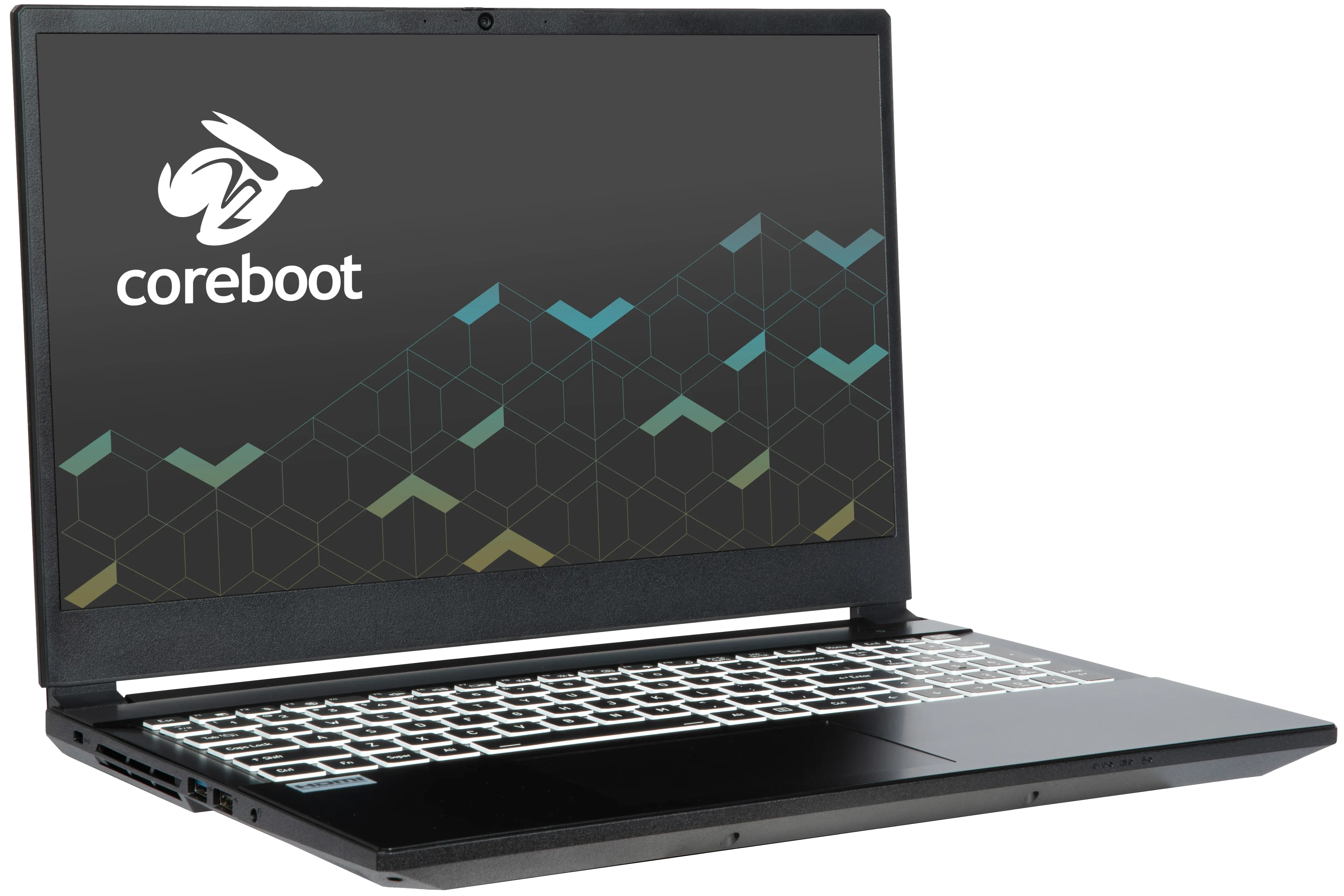
The System76 Gazelle is a laptop with the following specifications:
- CPU
- Supports Intel Core 2nd generation (Arrow Lake) CPUs
- Chipset
- BIOS
- GigaDevice GD25B256EYIGR flash chip
- WSON-8 form factor
- Programmed with System76 Open Firmware or non-open firmware
- GigaDevice GD25B256EYIGR flash chip
- EC
- ITE IT5570E
- Programmed with System76 EC or non-open EC firmware
- Graphics
- GPU: NVIDIA GeForce RTX 5050
- eDP display: 15.6" 1920x1080@144Hz LCD
- LCD panel: Innolux N156HRA-EA1 (or equivalent)
- Brightness: 250 nits (cd/m²)
- Color coverage:
- DCI-P3: 49%
- sRGB: 66%
- sRGB color coverage: 100
- LCD panel: Innolux N156HRA-EA1 (or equivalent)
- External video outputs:
- 1x HDMI 2.1
- 1x Mini DisplayPort 1.4
- 1x DisplayPort 1.4 over USB-C
- Memory
- Up to 64GB (2x32GB) dual-channel DDR5 SO-DIMMs @ 5600 MHz
- Networking
- Gigabit Ethernet
- M.2 PCIe/CNVi Wireless: Intel BE200
- WiFi 7
- Bluetooth 5.4
- Power
- 180W DC-in port
- Barrel size: 5.5mm (outer), 2.5mm (inner)
- Included AC adapter: LiteOn PA-1181-76
- AC power cord type: IEC C5
- 73Wh 4-cell Lithium-Ion battery
- Model number: V360BAT-4-73
- 180W DC-in port
- Sound
- Internal speakers & microphone
- Combined headphone & microphone 3.5mm jack
- HDMI, USB-C DisplayPort audio
- Storage
- 2x M.2 PCIe NVMe Gen 4
- USB
- 1x USB 3.2 Gen 2 Type-C
- Supports DisplayPort over USB-C
- Does not support USB-C charging (USB-PD)
- 1x USB 3.2 Gen 2 Type-A
- 1x USB 3.2 Gen 1 Type-A
- 1x USB 2.0 Type-A
- 1x USB 3.2 Gen 2 Type-C
- Dimensions
- 36.09cm x 24.69cm x 2.46cm, 2.25kg
Gazelle (External Overview)
Left side:
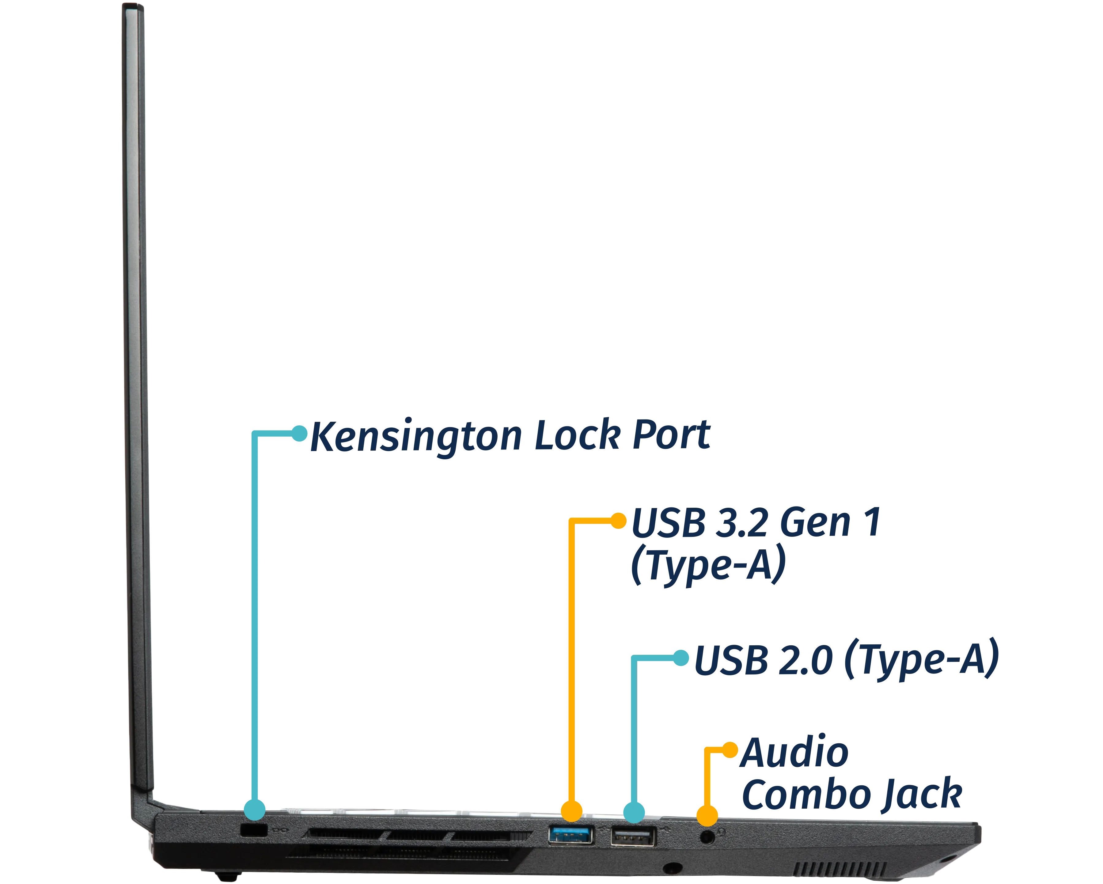
Right side:
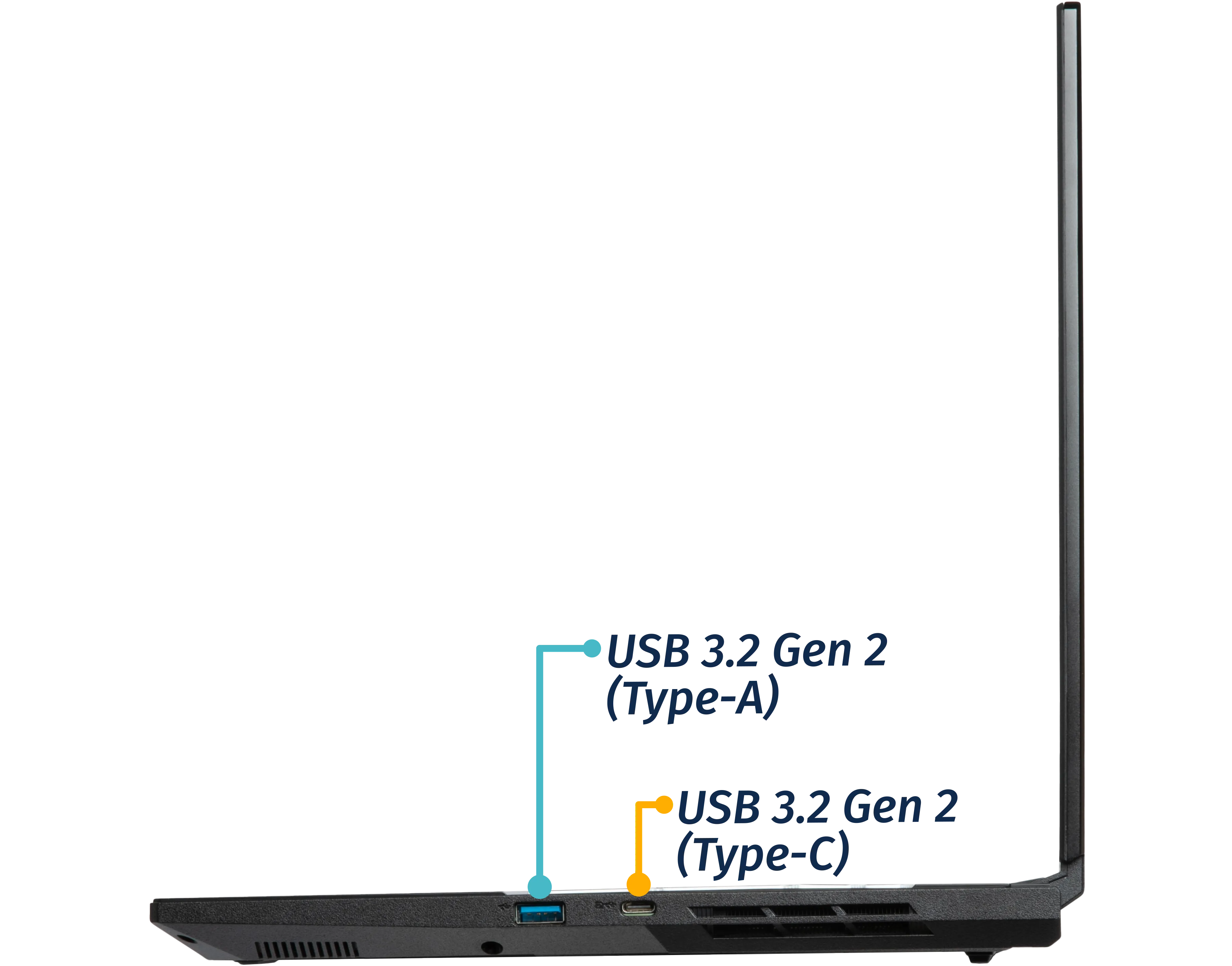
Front side:

Back side:

Keyboard & touchpad:

Lid:

Materials:
| Part | Material | Part Number |
|---|---|---|
| LCD back cover (lid) | Aluminum | 6-39-V2551-022 |
| LCD front cover (bezel) | Plastic | 6-39-V2551-012 |
| Top case (palm rests/port covers) | Plastic | 6-39-V2552-012 |
| Bottom panel | Plastic | 6-39-V2553-012 |
LED indicators:
The Gazelle has the following LED indicators:
| Icon | Color | Description |
|---|---|---|
 | Orange | Powered off, DC power plugged in |
| Green | Powered on | |
| Blinking green | Sleeping (suspended) | |
 | Orange | Battery charging |
| Green | Battery fully charged | |
| Blinking orange | Battery critically low | |
 | Green | Storage drive activity |
Keyboard shortcuts:
The Gazelle has the following actions available using the Fn and Function keys:
| Key | Shortcut | Action |
|---|---|---|
 | Fn+F1 | Toggle trackpad |
 | Fn+F2 | Mute/unmute microphone |
 | Fn+F3 | Mute/unmute speakers |
 | Fn+F5 | Volume down |
 | Fn+F6 | Volume up |
 | Fn+F7 | Toggle displays |
 | Fn+F8 | Screen brightness down |
 | Fn+F9 | Screen brightness up |
 | Fn+F10 | Toggle webcam |
 | Fn+F11 | Toggle airplane mode |
 | Fn+F12 | Suspend |
 | Fn+` | Play/Pause |
 | Fn+* | Toggle keyboard backlight |
 | Fn+/ | Cycle keyboard color |
 | Fn+- | Decrease keyboard brightness |
 | Fn++ | Increase keyboard brightness |
| 1 | Fn+1 | Toggle fan between max/automatic |
Gazelle (Internal Overview)
Bottom components and connectors:

- LCD panel connector is highlighted in light green
- Webcam/microphone connector is highlighted in cyan
- Keyboard adhesive access point is highlighted in pink
- Keyboard adhesive access point is under the heatsink
- Fan connectors are highlighted in red
- Speaker connectors are highlighted in yellow
- CMOS battery connector is highlighted in purple
- Wireless card is highlighted in blue
- Main battery connector is highlighted in orange
- RAM is highlighted in maroon
- BIOS flash chip (U46) is highlighted in black
- Touchpad connector is highlighted in white
- M.2 SSDs are highlighted in dark green
- Both slots support PCIe NVMe Gen 4
Under-keyboard components and connectors:

- Keyboard adhesive access point is highlighted in green
- Keyboard connector is highlighted in yellow
- Keyboard backlight connector is highlighted in cyan
- Power button/LED connector is highlighted in red
Gazelle (Parts & Repairs)
Many components in your Gazelle can be upgraded or replaced as necessary. Follow these step-by-step guides for instructions:
- Removing the bottom cover
- Replacing the RAM
- Replacing an M.2/NVMe SSD
- Replacing the WiFi/Bluetooth module
- Replacing the battery
- Replacing the CMOS battery
- Replacing the fans/heatsink/thermal paste
- Replacing the keyboard
- Replacing the speakers
Removing the bottom cover:
Removing the cover is required to access the internal components. Prior to removing the cover, ensure the AC power is unplugged and all peripherals (including SD cards and USB drives) are unplugged or removed from the system.
Part numbers:
- Bottom cover:
6-39-V2553-012
Tools required: Cross-head (Phillips) screwdriver
Time estimate: 5 minutes
Difficulty: Easy ●
Steps to remove the bottom cover:
- Place the machine lid-side down.
- Use a soft surface (such as a towel) to avoid scratches.
- Remove the 13 bottom panel screws.

- Pull the bottom panel off, starting from over the ports in the back.
Replacing the RAM:
The Gazelle 20 supports up to 64GB (2x32GB) of DDR5 SO-DIMMs running at 5600MHz. If you've purchased new RAM, need to replace your RAM, or are reseating your RAM, follow these steps.
Tools required: Cross-head (Phillips) screwdriver
Time estimate: 7 minutes
Difficulty: Easy ●
Steps to replace the RAM:
- Follow the steps above to remove the bottom cover.
- Pull the small tabs on both sides of the RAM simultaneously. The RAM should spring up to an angle.

- Remove the RAM from the slot.
- Insert the new RAM (or reseat the existing RAM) by placing it in the keyed slot and pressing down until it clicks into place.
Replacing an M.2/NVMe SSD:
This model supports up to two M.2 SSDs. Both M.2 slots are size 2280 and support PCIe NVMe Generation 4.
Tools required: Cross-head (Phillips) screwdriver
Time estimate: 10 minutes
Difficulty: Easy ●
Steps to replace the M.2 drive:
- Follow the steps above to remove the bottom cover.
- Unscrew the retainer screw opposite the M.2 slot.

- Remove the existing M.2 drive by pulling it out of the slot.
- Insert the new M.2 drive into the slot and hold it in place.
- Replace the retainer screw.
Replacing the wireless card:
Your Gazelle's WiFi and Bluetooth are both handled by the same module. It is a standard M.2 2230 slot with PCIe and USB interfaces (E-key).
Part number:
- The standard wireless card is an Intel
BE200.
Tools required: Cross-head (Phillips) screwdriver
Time estimate: 10 minutes
Difficulty: Medium ●
Steps to replace the WiFi/Bluetooth module:
- Follow the steps above to remove the bottom cover.
- Unscrew the wireless card screw holding the card and its wire bracket in place.

- Remove the metal bracket that holds the wires onto the card. The wireless card will pop up at an angle.
- Gently remove the two antennas (highlighted red below) by pulling them up and away from the wireless card.

- Remove the card from the M.2 slot.
- Insert the new wireless card into the M.2 slot at an angle.
- Attach the two antennas by aligning the circular fittings and pressing onto the wireless card. The connectors will snap into place.
- Use caution when attaching the connectors; the pins can bend, break, or snap.
- While holding the end of the card down, replace the metal bracket and the retaining screw.
- Replace the bottom cover.
Replacing the battery:
The battery provides primary power whenever the system is unplugged.
Part numbers:
- The battery's model number is
V360BAT-4-73, and the original part number is6-87-V35WS-73G00.- Third-party battery sellers may list one or both of these numbers, and may offer other compatible part numbers with the same model number.
- You can also contact System76 to purchase a replacement battery.
Tools required: Cross-head (Phillips) screwdriver
Time estimate: 8 minutes
Difficulty: Easy ●
Steps to replace the battery:
- Follow the steps above to remove the bottom cover.
- Remove the five battery screws, highlighted yellow below.

- Unplug the battery connector (highlighted red above) and lift the battery out of the chassis.
- Install the new battery and replace the bottom cover.
Replacing the CMOS battery:
The CMOS battery supplies power to the system's CMOS chip. UEFI settings and the computer's hardware clock are stored on the CMOS. If your system doesn't boot, you can reset the CMOS to force a low-level hardware reset. If your clock is constantly resetting, it's likely your CMOS battery needs to be replaced.
Warning (ingestion hazard): Keep batteries out of reach of children. Death or serious injury can occur if ingested. If a battery is suspected to be swallowed or inserted inside any part of the body, seek immediate medical attention. In the US, you can also call the National Battery Ingestion Hotline for guidance: +1 (800) 498-8666
Part numbers:
- The CMOS battery is a standard 3V KTS CR2032W battery.
Tools required: Cross-head (Phillips) screwdriver
Time estimate: 15 minutes
Difficulty: Medium ●
Steps to replace the CMOS battery:
- Follow the steps above to remove the bottom cover.
- If you're replacing the CMOS battery, remove the main battery.
- If you're clearing the CMOS without replacing the CMOS battery, you still need to unplug the main battery, but don't need to remove it.
- Unplug the white connector (labeled
RTC) that connects the CMOS battery to the motherboard.

- If you are replacing the CMOS battery, gently pull from the sides to pry it up from where it's stuck to the case.
- To clear the CMOS, open the lid of the machine and hold down the power button for at least 15 seconds to discharge any residual energy in the system.
- Stick the new CMOS battery onto the chassis (if necessary) and reconnect the CMOS battery to the motherboard.
- Reinstall/reconnect the main battery and replace the bottom cover.
- Power up the Gazelle. The system may power itself off and on after initial boot; this is normal behavior when the CMOS has been reset.
Replacing the cooling system:
The Gazelle 20 has a single heatsink assembly with two fans. This assembly cools the CPU and GPU.
If the fans become noisy and cleaning them out doesn't fix the issue, you may need a new fan. Contact support to start a warranty claim or parts purchase. These instructions can also be used if physical damage to the heatsink necessitates its replacement.
Thermal paste helps facilitate effective heat transfer between the CPU/GPU and the cooling equipment; depending on your climate and the age of the machine, replacing the thermal paste may improve cooling performance. The thermal paste should generally be replaced whenever the heatsink is removed.
Thermal putty (thicker than thermal paste) is used to bridge the gap between the VRAM chips and the heatsink. Replacing the thermal putty is optional when removing the heatsink. System76 suggests Thermal Grizzly Putty Basic (available at various retailers) or a similar alternative.
Part numbers:
- Fan/heatsink assembly:
6-31-V25RN-202 - Left fan: Yingfan
5V2 - Right fan: Yingfan
DV3
Tools required: Cross-head (Phillips) screwdriver
Time estimate: 20 minutes
Difficulty: High ●
Steps to replace the fans/heatsink/thermal paste:
- Follow the steps above to remove the bottom cover.
- It's also recommended to remove the M.2 drive from slot 2 (if installed) for easier access to the fan wire.
- Remove any clear tape that is securing the fan wires.
- Remove the thirteen heatsink and fan screws.
- The 11 numbered screws should be unscrewed in order of the stamped numbers, starting with #1, then #2, and continuing until you have removed #11. The two unnumbered fan screws (marked
3V3and5V2) can be removed in any order. - The silver screw (#11) and the unnumbered fan screws will detatch when fully loosened. Screws #1-10 are held captive and will not completely detatch from the heatsink/fans.
- Do not remove the smaller black screws holding the fan covers onto the fans.
- The 11 numbered screws should be unscrewed in order of the stamped numbers, starting with #1, then #2, and continuing until you have removed #11. The two unnumbered fan screws (marked

- Unplug the two white fan connectors from the motherboard (highlighted green above).
- Remove the heatsink/fans from the case, being careful not to bend the heatsink pipes. It may take some pressure to break the seal of the thermal paste.
- Using a paper towel, remove the existing thermal paste. You may also use a small amount of rubbing alcohol if the old paste is dried or difficult to remove.
- You can optionally remove the thermal putty from the four VRAM chips surrounding the GPU chip if you have replacement thermal putty to install.

- After cleaning the CPU, GPU, and heatsink, apply a small line of thermal paste directly onto both CPU chips and the GPU chip.
- If you aren't replacing the thermal putty, scoop the existing putty (from the VRAM chip and the corresponding location on the heatsink) into the center of each VRAM chip using a flat plastic tool.

- Carefully replace the heatsink.
- Replace the heatsink and fan screws, starting with #1, then #2, and so on until #11; also replace the two unnumbered fan screws.
- Plug the two white fan connectors back into the motherboard.
Replacing the keyboard:
The keyboard can be replaced if its switches or electronics have been damaged.
Part numbers:
- The keyboard's model number is
CVM18H03US930FA, and its part number is6-80-PC510-013-1MD, also known as6-V256RNP-KB-MCL-US.- Keyboards shipped by System76 include a custom-printed Super key.
Tools required: Cross-head (Phillips) screwdriver, tweezers (optional)
Time estimate: 10 minutes
Difficulty: High ●
Steps to replace the keyboard:
- Follow the steps above to remove the bottom cover and remove the heatsink.
- Removing the heatsink isn't required if the adhesive is fed between the motherboard and the fan; by default, the adhesive is not fed through (meaning heatsink removal is required) due to its shape and size.
- Replacing the thermal paste is recommended whenever the heatsink is removed.
- Pull the keyboard adhesive out of the machine to detatch it from the keyboard.
- Pull the adhesive strip slowly to avoid breaking it. Grasp farther down the strip as it comes out of the machine (don't pull the end far away from the machine.)
- If the adhesive strip breaks, remove as much of it as possible. The keyboard can be reinstalled without the adhesive strip.
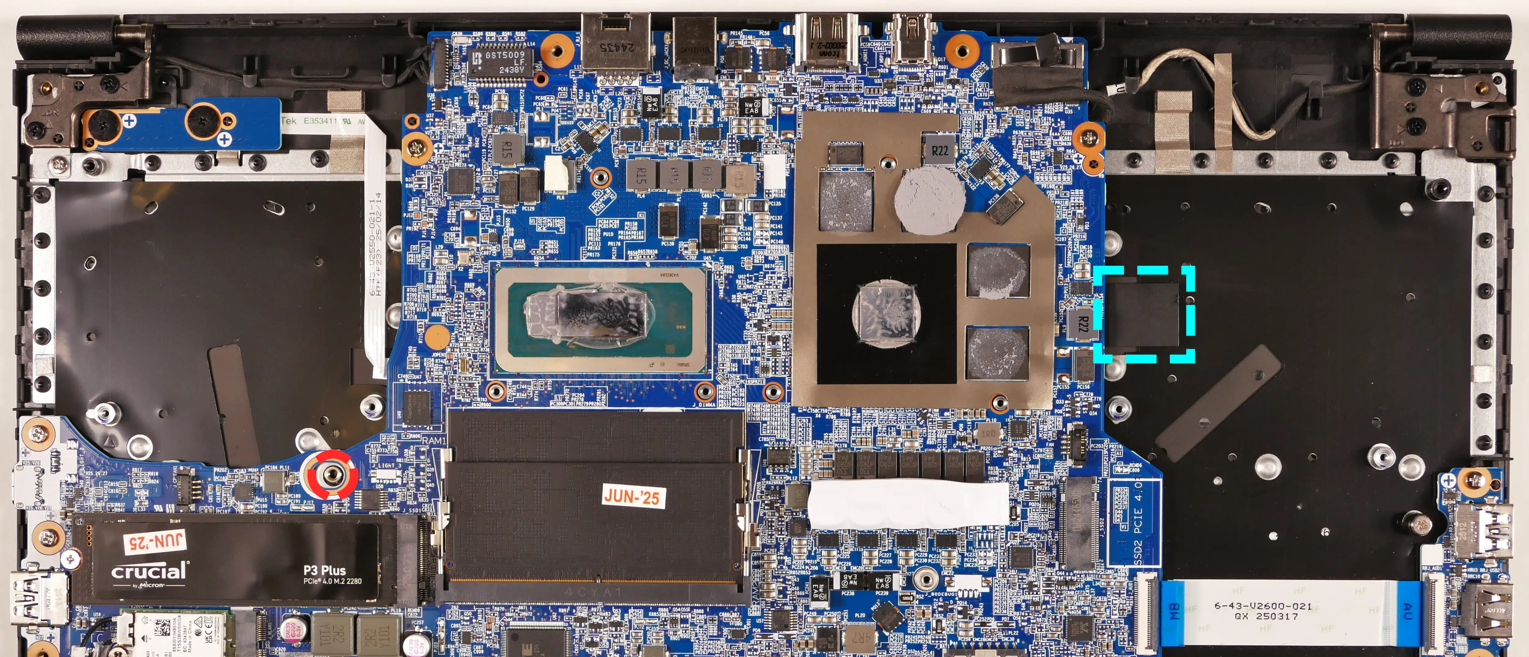
- Open the lid slightly and place the machine on its side.
- Push a screwdriver into the keyboard push point (highlighted red above) until the keyboard pops out.

- Set the machine back down and raise the keyboard away from the chassis. The larger ribbon cable is for the keyboard, while the smaller ribbon cable is for the keyboard backlight.

- Flip the black latches upwards to free the ribbon cables.
- Pull the ribbon cables out of the connectors.
- Remove the keyboard and replace it with the new one.
- Carefully slide both ribbon cables into their connectors.
- Flip the black latches back into place to secure the ribbon cables.
- (Optional) Replace the keyboard adhesive strip on the chassis.
- Place the keyboard back into position, starting with the tabs on the bottom edge.
- Secure the rest of the keyboard by pressing down on each of its edges.
- Turn the machine lid-side down again and replace the bottom cover.
Replacing the speakers:
The system has two bottom-firing speakers, which can be removed and replaced individually.
Part numbers:
- Left speaker:
6-23-5V25K-0L0 - Right speaker:
6-23-5V25K-0R0
Tools required: Cross-head (Phillips) screwdriver
Time estimate: 10 minutes
Difficulty: Easy ●
Steps to replace the speakers:
- Follow the steps above to remove the bottom cover.
- Disconnect the speaker wire from the motherboard.

- Unscrew the speaker screws (two per speaker) and lift the speaker out of the machine.
- The left speaker wire (pictured on the right) is partially routed through channels in the chassis; be careful when removing it.
- Place the new speaker in the machine.
- Plug in the connector, securing the wire in the chassis channels (for the left speaker).
- Replace the screws
- Reinstall the bottom panel.
Ibex Pro 2U (ibep2-b1)
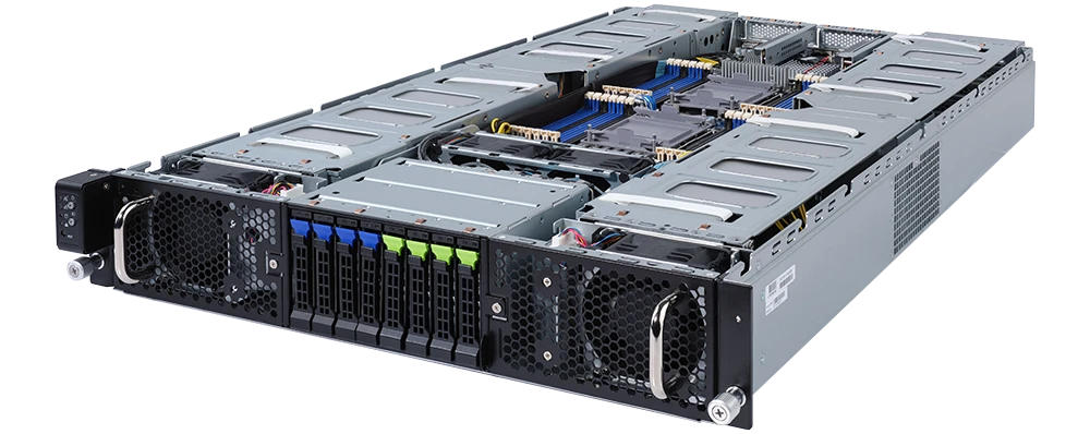
The System76 Ibex Pro 2U is a rack-mounted server. The B1 model code indicates the first revision based on an Intel platform. This model has the following specifications:
- Chassis
- CPU options
- Supports 2x Intel Xeon Scalable 3rd-generation processors
- Memory
- Up to 6144GB (24x256GB) ECC DDR4 @ 3200 MHz
- Storage
- 4x 2.5" NVMe Gen 4/SATA/SAS hot-swappable HDD/SSD bays
- 4x 2.5" SATA/SAS hot-swappable HDD/SSD bays
- Networking
- 2x 10GbE LAN ports (Intel X710-AT2)
- 1x 1GbE management LAN
- Expansion
- 8x PCIe Gen 4 x16 (full-height, full-length)
- 2x PCIe Gen 4 x16 (half-height, half-length)
- Front I/O
- 1x Power button with LED
- 1x ID button with LED
- 1x Reset button
- 1x System status LED
- 1x HDD activity LED
- 2x LAN activity LEDs
- Back I/O
- 2x USB 3.0
- 1x VGA
- 2x RJ45 (Ethernet)
- 1x Management LAN
- 1x Power button with LED
- 1x ID button with LED
- 1x Reset button
- 1x NMI button
- 1x System status LED
- Power Supply
- 2x 1200W redundant 80+ Platinum PSUs
- AC Input: 100-240V 16-14A, 50-60Hz
- Dimensions
- 44.8cm x 80.0cm x 8.75cm, 36kg
Ibex Pro 2U (ibep2-r1)
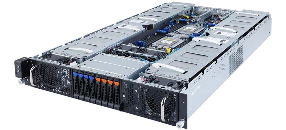
The System76 Ibex Pro 2U is a rack-mounted server. The R1 model code indicates the first revision based on an AMD platform. This model has the following specifications:
- Chassis
- CPU options
- Supports 2x AMD EPYC 7003-series or 7002-series processors
- Memory
- Up to 4096GB (16x256GB) ECC DDR4 @ 3200 MHz
- Storage
- 4x 2.5" NVMe Gen 3/SATA/SAS hot-swappable HDD/SSD bays
- 4x 2.5" SATA/SAS hot-swappable HDD/SSD bays
- Networking
- 2x 10GbE LAN ports (1x Intel X550-AT2)
- 1x 1GbE management LAN
- Expansion
- 8x PCIe Gen 4 x16 (full-height, full-length)
- 2x PCIe Gen 4 x16 (half-height, half-length)
- Front I/O
- 1x Power button with LED
- 1x ID button with LED
- 1x Reset button
- 1x System status LED
- 1x HDD activity LED
- 2x LAN activity LEDs
- Back I/O
- 2x USB 3.0
- 1x VGA
- 2x RJ45 (Ethernet)
- 1x Management LAN
- 1x Power button with LED
- 1x ID button with LED
- 1x Reset button
- 1x NMI button
- 1x System status LED
- Power Supply
- 2x 1200W redundant 80+ Platinum PSUs
- AC Input: 100-240V 14-12A, 50-60Hz
- Dimensions
- 44.8cm x 80.0cm x 8.75cm, 36kg
Jackal Pro 1U (jacp1-b2)
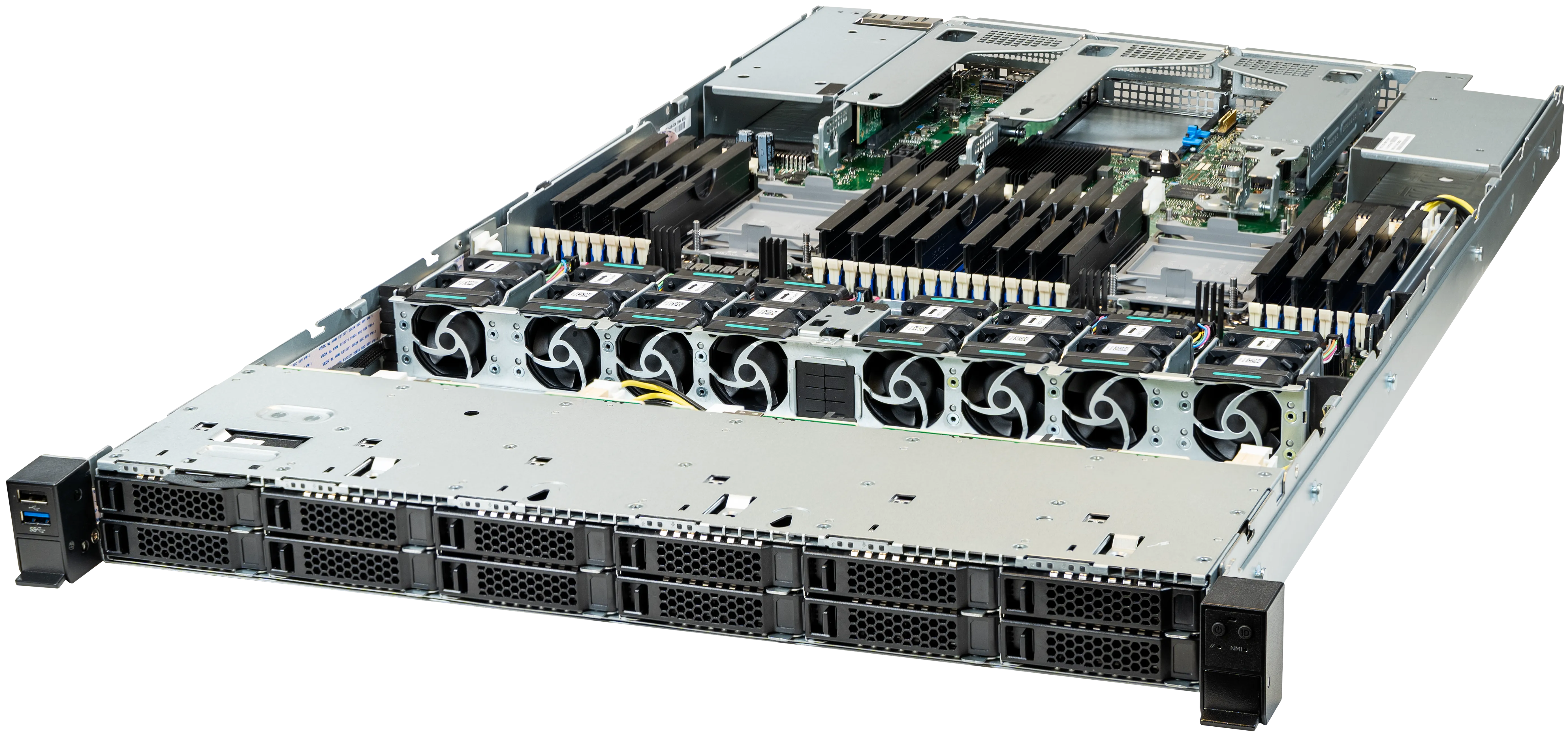
The System76 Jackal Pro 1U is a rack-mounted server. The B2 model code indicates the second revision based on an Intel platform. This model has the following specifications:
- Chassis
- CPU options
- Supports 2x Intel Xeon Scalable 3rd-generation processors
- Memory
- Up to 8192GB (32x256GB) ECC DDR4 @ 3200 MHz
- Storage
- Front:
- 12x 2.5" SATA/SAS hot-swappable HDD/SSD bays
- Internal:
- 2x M.2 PCIe NVMe Gen 3 slots
- Front:
- Networking
- 2x 1GbE LAN ports
- Expansion
- Riser Slot 1: PCIe 4.0, 32 lanes
- Preinstalled riser card: x16 slot
- Riser Slot 2: PCIe 4.0, 32 lanes
- Preinstalled riser card options:
- Option 1: x16 slot
- Option 2: x16 slot and x8 slot
- Preinstalled riser card options:
- Riser Slot 3: PCIe 4.0, 16 lanes
- Preinstalled riser card: two x8 slots
- Riser Slot 1: PCIe 4.0, 32 lanes
- Front I/O
- 1x USB 3.0
- 1x USB 2.0
- 1x Power button with LED
- 1x ID button with LED
- 1x Cold reset button (tool required)
- 1x NMI button (tool required)
- 1x System status LED
- 1x Drive activity LED
- Back I/O
- 3x USB 3.0
- 1x VGA
- 2x RJ45 (Ethernet)
- 1x Management LAN
- 1x RJ45 (Serial)
- Power Supply
- 1x 1300W High Efficiency PSU
- Optional second (redundant) PSU
- 1x 1300W High Efficiency PSU
- Dimensions
- 43.8cm x 78.1cm x 4.3cm, 17.24kg
Jackal Pro 2U (jacp2-b2)
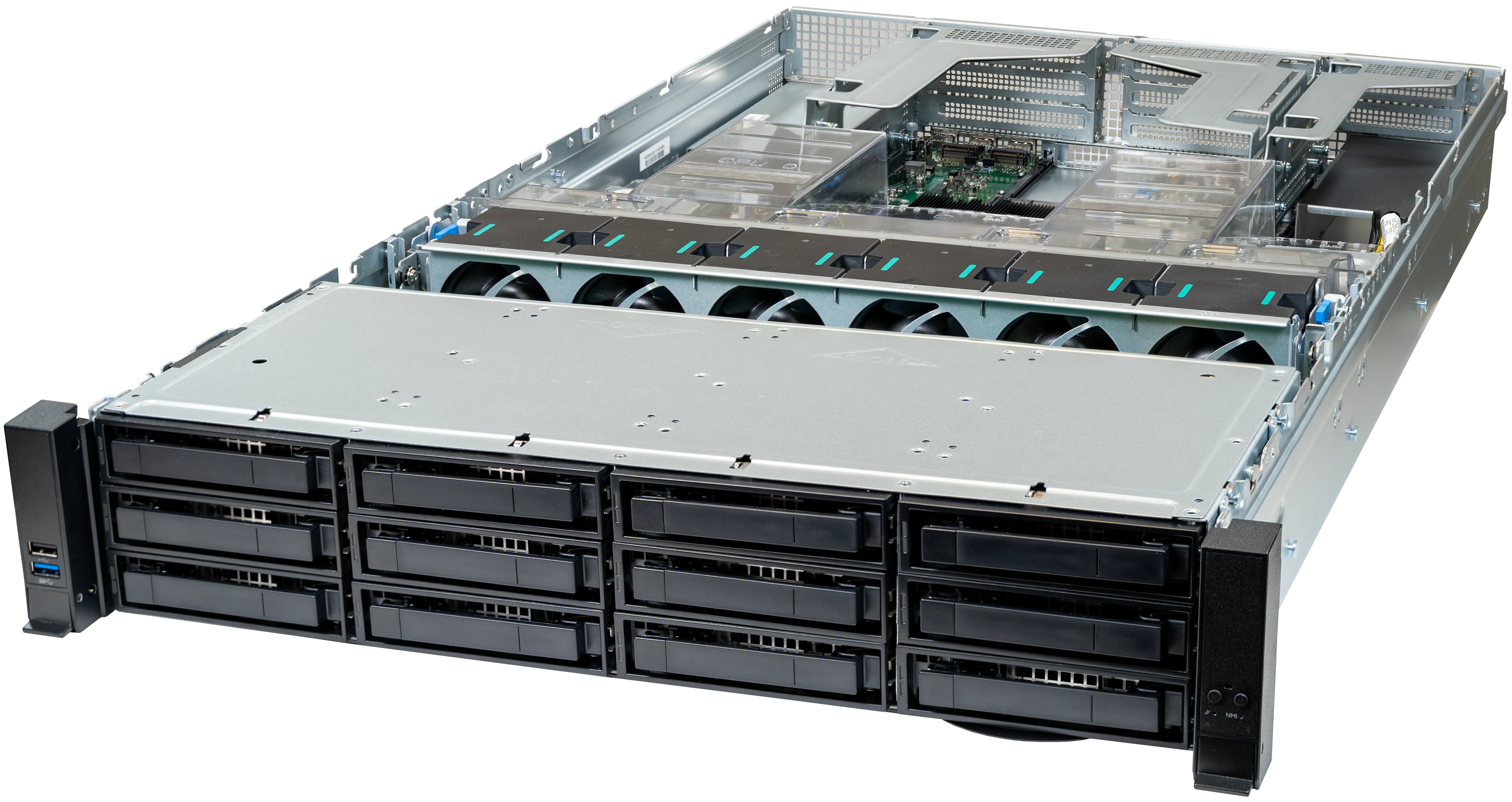
The System76 Jackal Pro 2U is a rack-mounted server. The B2 model code indicates the second revision based on an Intel platform. This model has the following specifications:
- Chassis
- CPU options
- Supports 2x Intel Xeon Scalable 3rd-generation processors
- Memory
- Up to 8192GB (32x256GB) ECC DDR4 @ 3200 MHz
- Storage
- Front:
- 12x 3.5" SATA/SAS hot-swappable HDD/SSD bays
- Internal:
- 2x M.2 PCIe NVMe Gen 3 slots
- Front:
- Networking
- 2x 1GbE LAN ports
- Expansion
- Riser Slot 1: PCIe 4.0, 32 lanes
- Preinstalled riser card options:
- Option 1: one x16 slot and two x8 slots
- Option 2: two x16 slots
- Preinstalled riser card options:
- Riser Slot 2: PCIe 4.0, 32 lanes
- Preinstalled riser card options:
- Option 1: one x16 slot and two x8 slots
- Option 2: two x16 slots
- Preinstalled riser card options:
- Riser Slot 3: PCIe 4.0, 16 lanes
- Preinstalled riser card: two x8 slots
- Riser Slot 1: PCIe 4.0, 32 lanes
- Front I/O
- 1x USB 3.0
- 1x USB 2.0
- 1x Power button with LED
- 1x ID button with LED
- 1x Cold reset button (tool required)
- 1x NMI button (tool required)
- 1x System status LED
- 1x Drive activity LED
- Back I/O
- 3x USB 3.0
- 1x VGA
- 2x RJ45 (Ethernet)
- 1x Management LAN
- 1x RJ45 (Serial)
- Power Supply
- 1x 1300W High Efficiency PSU
- Optional second (redundant) PSU
- 1x 1300W High Efficiency PSU
- Dimensions
- 43.9cm x 71.2cm x 8.9cm, 17.24kg
Kudu (kudu6)
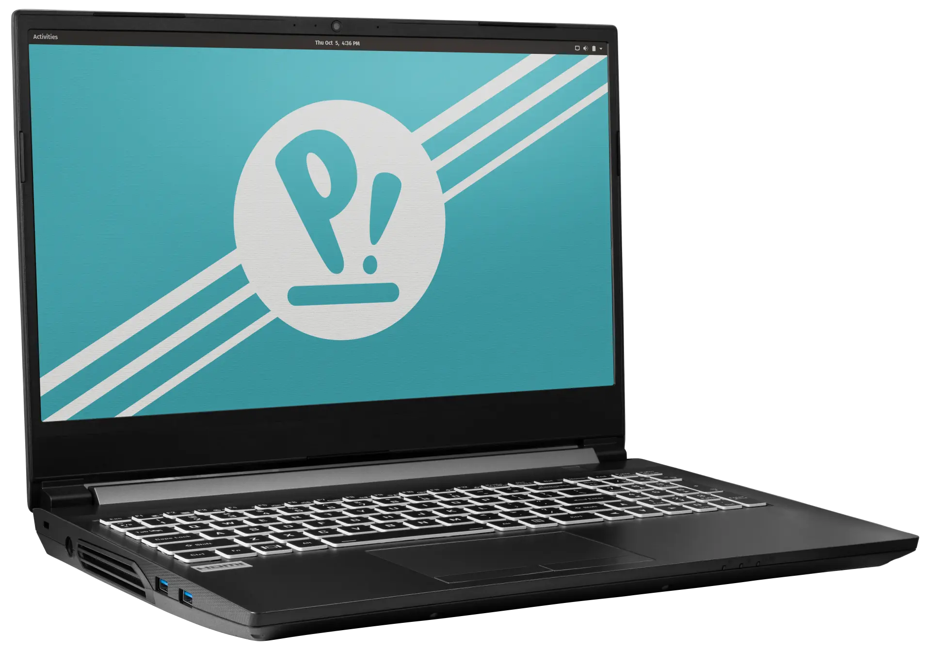
The System76 Kudu is a laptop with the following specifications:
- CPU
- Supports AMD Ryzen (Cezanne) Mobile CPUs
- BIOS
- W74M12JWSSIQ flash chip
- SOIC-8 form factor
- Programmed with System76 firmware (non-open)
- W74M12JWSSIQ flash chip
- EC
- ITE IT5570E
- Programmed with non-open EC firmware
- Graphics
- Dedicated GPU:
- NVIDIA GeForce RTX 3060
- TGP: 60W
- NVIDIA GeForce RTX 3060
- Integrated GPU:
- AMD Radeon RX Vega 8
- eDP display options:
- 15.6" 1920x1080@144Hz LCD
- LCD panel: AUO B156HAN08.4 (or equivalent)
- 15.6" 1920x1080@144Hz LCD
- External video output:
- 1x HDMI 2.1
- 1x Mini DisplayPort 1.4
- 1x DisplayPort 1.4 over USB-C
- Dedicated GPU:
- Memory
- Up to 64GB (2x32GB) dual-channel DDR4 SO-DIMMs @ 3200 MHz
- Networking
- 2.5-Gigabit Ethernet
- M.2 PCIe/CNVi WiFi/Bluetooth
- Intel Wi-Fi 6 AX200/AX201
- Power
- 230W (19.5V, 11.8A) DC-in port
- Barrel size: 5.5mm (outer), 2.5mm (inner)
- Included AC adapter: Chicony A17-230P1A
- AC power cord type: IEC C13
- 48.96Wh 4-cell Lithium-Ion battery
- Model number: NH50BAT-4
- 230W (19.5V, 11.8A) DC-in port
- Sound
- Internal speakers & microphone
- Combined headphone & microphone 3.5mm jack
- Dedicated microphone 3.5mm jack
- HDMI, Mini DisplayPort, USB-C DisplayPort audio
- Storage
- 2x M.2 (PCIe NVMe Gen 3)
- USB
- 1x USB 3.2 Gen 2 Type-C
- Supports DisplayPort over USB-C
- Does not support USB-C charging (USB-PD) or Thunderbolt
- 1x USB 3.2 Gen 2 Type-A
- 1x USB 3.2 Gen 1 Type-A
- 1x USB 2.0 Type-A
- 1x USB 3.2 Gen 2 Type-C
- Dimensions
- 15": 36.1cm x 25.8cm x 2.9cm, 2.2kg
Kudu (External Overview)
Left side overview:

Right side overview:

Front side overview:

Back side overview:

Materials:
| Part | Material |
|---|---|
| LCD back cover (lid) | Aluminum |
| LCD front cover (bezel) | Plastic |
| Top case (palm rests/port covers) | Plastic |
| Bottom panel | Plastic |
LED indicators:
| Icon | Color | Description |
|---|---|---|
 | Orange | Powered off, DC power plugged in |
| Green | Powered on | |
| Blinking green | Sleeping (suspended) | |
 | Orange | Battery charging |
| Green | Battery fully charged | |
| Blinking orange | Battery critically low | |
 | Green | Storage drive activity |
Keyboard shortcuts:
| Key | Shortcut | Action |
|---|---|---|
 | Fn+F1 | Toggle trackpad |
 | Fn+F2 | Toggle built-in LCD |
 | Fn+F3 | Mute |
 | Fn+F5 | Volume down |
 | Fn+F6 | Volume up |
 | Fn+F7 | Toggle displays |
 | Fn+F8 | Screen brightness down |
 | Fn+F9 | Screen brightness up |
 | Fn+F10 | Toggle webcam |
 | Fn+F11 | Toggle airplane mode |
 | Fn+F12 | Suspend |
 | Fn+` | Play/Pause |
 | Fn+* | Toggle keyboard backlight |
| / | Fn+/ | Cycle keyboard color |
| - | Fn+- | Decrease keyboard brightness |
| + | Fn++ | Increase keyboard brightness |
Kudu (Internal Overview)
Bottom components and connectors:

- Webcam/microphone connector is highlighted in cyan
- LCD panel connector is highlighted in pink
- DC-in power connector is highlighted in red
- BIOS flash chip (U51) is highlighted in black
- Fan connectors are highlighted in orange
- RAM is highlighted in dotted green
- M.2 SSDs are highlighted in dotted yellow
- Wireless card is highlighted in blue
- Touchpad connector is highlighted in white
- Speaker connectors are highlighted in solid yellow
- CMOS battery is highlighted in solid green
Under-keyboard components and connectors:

- Keyboard connector is highlighted in yellow
- Keyboard backlight connector is highlighted in red
- Power button/LED connector is highlighted in cyan
- Front LED connector is highlighted in green
Kudu (Parts & Repairs)
Many components in your Kudu can be upgraded or replaced as necessary. Follow these step-by-step guides for instructions:
- Removing the battery
- Removing the bottom cover
- Replacing the RAM
- Replacing an M.2/NVMe SSD
- Replacing the WiFi/Bluetooth module
- Replacing the CMOS battery
- Replacing the fans/heatsink/thermal paste
- Replacing the DC-in jack
- Replacing the keyboard
Removing the battery:
The battery provides primary power whenever the system is unplugged.
The model number for the Kudu 6's battery is NH50BAT-4, and the original part number is 6-87-NH50S-42D01. Third-party battery sellers may list one or both of these numbers, and may offer other compatible part numbers with the same model number. You can also contact System76 to purchase a replacement battery.
Tools required: None
Time estimate: 1 minute
Difficulty: Easy ●
Steps to remove the battery:
- Place the machine lid-side down.
- Use a soft surface (such as a towel) to avoid scratches.
- Slide the locking slider (highlighted cyan below) into the unlocked position.

- While holding the springing slider (highlighted red above) in the unlocked position, grasp the tab in the corner and lift the battery out of the machine.
Removing the bottom cover:
Removing the cover is required to access the internal components. Prior to removing the cover, ensure the AC power is unplugged and all peripherals (such as USB drives) are unplugged or removed from the system.
Tools required: Cross-head (Phillips) screwdriver
Time estimate: 5 minutes
Difficulty: Easy ●
Steps to remove the bottom cover:
- Follow the steps above to remove the battery.
- Remove the 16 bottom panel screws.
- The silver hinge screw (highlighted cyan below) is slightly shorter than the rest.

- Pull the bottom panel off of the case, starting behind the battery slot.
Replacing the RAM:
The Kudu 6 supports up to 64GB (2x32GB) of DDR4 SO-DIMMs running at 3200MHz. If you've purchased new RAM, need to replace your RAM, or are reseating your RAM, follow these steps.
Tools required: Cross-head (Phillips) screwdriver
Time estimate: 10 minutes
Difficulty: Easy ●
Steps to replace the RAM:
- Follow the steps above to remove the battery and remove the bottom cover.
- Press the small tabs on both sides of the RAM simultaneously. The RAM should spring up to an angle.

- Remove the RAM from the slot.
- Insert the new RAM (or reseat the existing RAM) by placing it in the keyed slot and pressing down on the RAM until it clicks into place.
Replacing an M.2/NVMe SSD:
This model supports up to two M.2 SSDs. Both M.2 slots are size 2280, and both slots support PCIe NVMe Generation 3 only.
Tools required: Cross-head (Phillips) screwdriver
Time estimate: 10 minutes
Difficulty: Easy ●
Steps to replace the M.2 drive:
- Follow the steps above to remove the battery and remove the bottom cover.
- Unscrew the retainer screw opposite the M.2 slot.

- Remove the existing M.2 drive by pulling it out of the slot.
- Insert the new M.2 drive into the slot and hold it in place.
- Replace the retainer screw.
Replacing the wireless card:
Your Kudu's WiFi and Bluetooth are both handled by the same module. It is a standard M.2 2230 slot with PCIe and USB interfaces (E-key).
Tools required: Cross-head (Phillips) screwdriver
Time estimate: 10 minutes
Difficulty: Medium ●
Steps to replace the WiFi/Bluetooth module:
- Follow the steps above to remove the battery and remove the bottom cover.
- Locate the wireless module. Remove any clear tape that is securing the wires.

- Gently remove the two antennas (highlighted red above) by pulling them up and away from the wireless card.
- Remove the retaining screw opposite the M.2 slot, highlighted yellow above.
- The wireless card will pop up at an angle. Remove the card from the M.2 slot.
- Insert the new wireless card into the M.2 slot at an angle.
- Replace the retaining screw.
- Attach the two antennas by aligning the circular fittings and pressing onto the wireless card. The connectors will snap into place. Use caution when attaching the connectors; the pins can bend, break, or snap.
Replacing the CMOS battery:
The CMOS battery supplies power to the system's CMOS chip. UEFI settings and the computer's hardware clock are stored on the CMOS. If your system doesn't boot, you can reset the CMOS to force a low-level hardware reset. If your clock is constantly resetting, it's likely your CMOS battery needs to be replaced.
Warning (ingestion hazard): Keep batteries out of reach of children. Death or serious injury can occur if ingested. If a battery is suspected to be swallowed or inserted inside any part of the body, seek immediate medical attention. In the US, you can also call the National Battery Ingestion Hotline for guidance: 1 (800) 498-8666
Tools required: Cross-head (Phillips) screwdriver
Time estimate: 15 minutes
Difficulty: Medium ●
Steps to replace the CMOS battery:
- Follow the steps above to remove the main battery and remove the bottom cover.
- Unplug the small white connector that connects the CMOS battery to the motherboard.
- If you are replacing the battery, remove any clear tape, then gently pull from the sides to pry it up from where it's stuck to the case.

- To clear the CMOS, open the lid of the machine and hold down the power button for at least 15 seconds to discharge any residual energy in the system.
- Re-connect the CMOS battery, replace the bottom panel, and replace the main battery.
- Power up the Kudu. The system may power itself off and on after initial boot; this is normal behavior when the CMOS has been reset.
Replacing the cooling system:
The Kudu 6 has a single heatsink for the CPU and GPU. One fan is attached to the heatsink, while the other fan is separate from the heatsink.
If the fans become noisy and cleaning them out doesn't fix the issue, you may need a new fan. Contact Support to start a warranty claim or parts purchase.
Depending on your climate and the age of the machine, it may be necessary to apply new thermal paste between the CPU/GPU and the heatsink. Thermal paste helps facilitate effective heat transfer between the CPU/GPU and the cooling equipment. These instructions can also be used in the unlikely event that your heatsink needs to be replaced.
Tools required: Cross-head (Phillips) screwdriver
Time estimate: 20 minutes
Difficulty: High ●
Steps to replace the standalone fan:
- Follow the steps above to remove the battery and remove the bottom cover.
- Locate the standalone fan.
- The standalone fan is located between the battery slot and the M.2 drives, next to the DC-in port.
- If there is any clear tape on the fan securing the DC-in cable, remove it.
- Remove the three screws attaching the standalone fan to the chassis.
- Do not remove the smaller screws holding the fan's cover on.
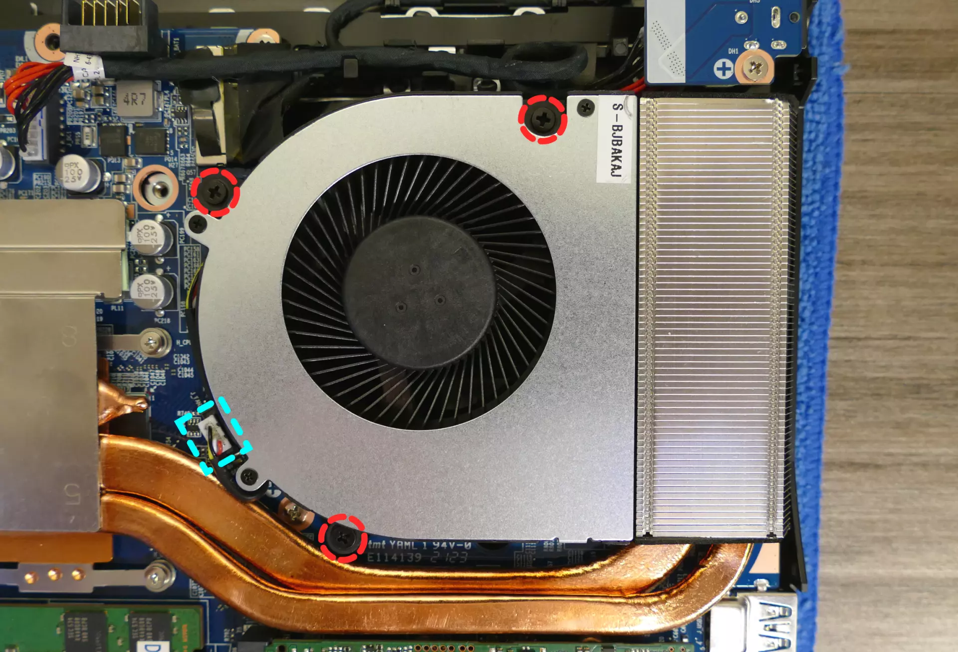
- Unplug the fan connector, highlighted cyan above.
- Lift the fan out of the system.
- The fan grill at the edge of the chassis is part of the heatsink, and will not lift out with the fan.
Steps to replace the heatsink/thermal paste:
- Follow the steps above to remove the standalone fan.
- Removing the standalone fan is not physically required, but is recommended to ensure the heatsink is reinstalled properly.
- Remove the heatsink and fan screws in the order of the stamped numbers, starting with #1, then #2, and continuing until you have removed #10.
- The first four screws (#1 - #4) are held captive and will not pull away from the heat sink when loosened.

- Unplug the white fan connector from the motherboard (highlighted cyan above).
- Remove the heatsink/fan from the case, being careful not to bend the heatsink pipes. It may take some pressure to break the seal of the thermal paste.
- Using a paper towel, remove the existing thermal paste. You may also use a small amount of rubbing alcohol if the old paste is dried or difficult to remove.

- After cleaning the CPU, GPU, and heatsink, apply a small line of thermal paste directly onto the CPU and GPU chips.

- Carefully replace the heatsink.
- Replace the silver heatsink screws, starting with #1, then #2, and so on until #6.
- Replace the black fan screws.
- Plug the two white fan connectors back into the motherboard.
Replacing the DC-in jack:
If the DC-in jack (power port) is no longer making contact with the barrel charger, and replacing the charger doesn't fix the issue, the DC-in jack can be replaced.
Tools required: Cross-head (Phillips) screwdriver
Time estimate: 10 minutes
Difficulty: Easy ●
Steps to replace the DC-in jack:
- Follow the steps above to remove the battery and remove the bottom cover.
- Remove any clear tape securing the internal DC-in cable.
- Unscrew the two screws holding the DC-in connector onto the chassis, highlighted cyan below.
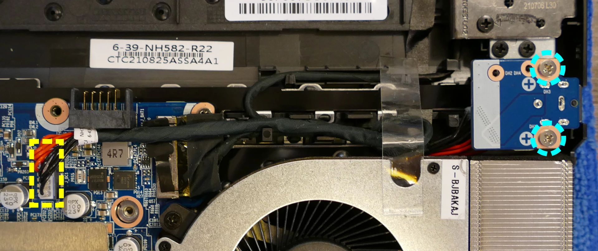
- Unplug the internal DC-in cable from the motherboard.
- Plug in the new cable, replace the screws, and (optionally) replace the tape.
Replacing the keyboard:
Keyboard replacement is simple and requires only a cross-head screwdriver.
Tools required: Cross-head (Phillips) screwdriver
Time estimate: 5 minutes
Difficulty: Medium ●
Steps to replace the keyboard:
- Place the machine lid-side down.
- Use a soft surface (such as a towel) to avoid scratches.
- Remove the 2 keyboard screws, indicated by the small keyboard icons.

- Open the lid slightly and place the machine on its side.
- Push the screwdriver into the keyboard push point (highlighted red above) until the keyboard pops out.

- Set the machine back down and raise the keyboard away from the chassis. The larger ribbon cable is for the keyboard, while the smaller ribbon cable is for the keyboard backlight.

- Flip the black latches upwards to free the ribbon cables.
- Pull the ribbon cables out of the connectors.
- Remove the keyboard and replace it with the new one.
- Carefully slide both ribbon cables into their connectors.
- Flip the black latches back into place to secure the ribbon cables.
- Place the keyboard back into position, starting with the tabs on the bottom edge.
- Secure the rest of the keyboard by pressing down on each of its edges.
- Turn the machine lid-side down again and replace the two keyboard screws.
Launch (launch_3)
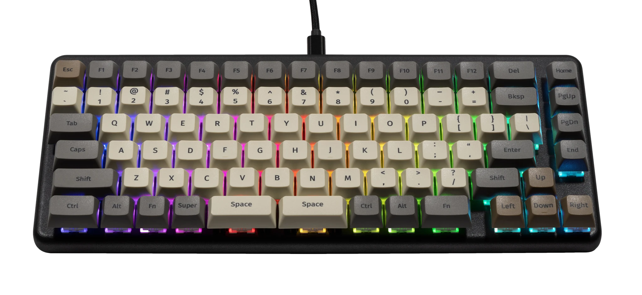
The System76 Launch is a configurable keyboard with the following specifications:
- Chassis
- Open-source milled chassis design
- Magnetically-attachable 15-degree angle lift bar
- Electronics
- Open-source PCB design
- Individually addressable RGB LED backlighting
- N-key rollover
- Sockets and Switches
- Kailh MX hot swap sockets
- Default switch options:
- NovelKeys x Kailh Box Jade
- NovelKeys x Kailh Box Royal
- Kailh Box Silent Brown
- Kailh Box Silent Pink
- Keycaps
- PBT plastic
- Dye sublimated legend
- XDA profile
- Sizes:
- 3x 2U keycaps (both
Spacebars and leftShift)- All three 2U caps use plate-mount stabilizers
- 8x 1.5U keycaps (
Tab,Caps, leftCtrl, rightFn, rightShift,Enter,Bksp, andDel) - 73x 1U keycaps
- 3x 2U keycaps (both
- Layout
- Modified ANSI US QWERTY
- Custom Configurations
- Customize layout and lighting in firmware with the System76 Keyboard Configurator
- Available on Linux, Windows, and macOS
- Integrated Hub
- 2x USB 3.2 Gen 2 Type-C
- 2x USB 3.2 Gen 2 Type-A
- Firmware
- Included cables:
- 1x USB Type-C to USB Type-C
- 1x USB Type-C to USB Type-A
- Dimensions
- 30.83cm x 13.51cm x 3.061cm, 948g
Launch (External Overview)
Top overview:
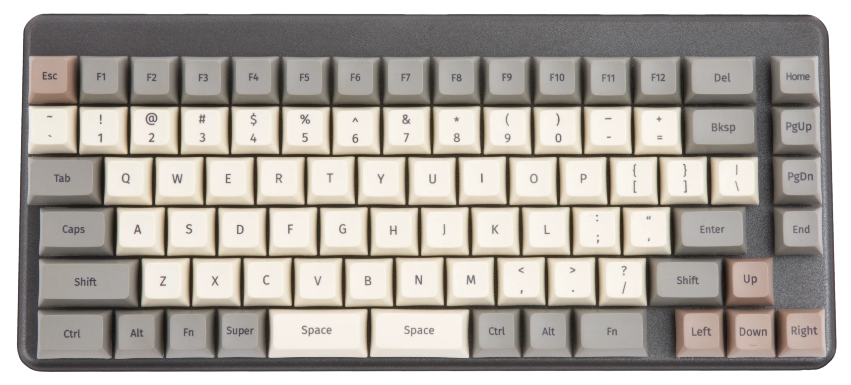
Back overview:

Box contents overview:
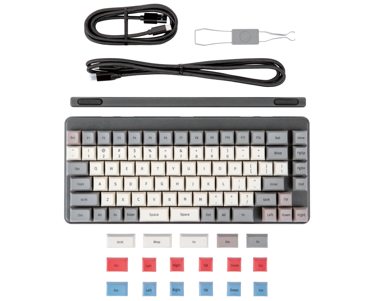
Launch (Customization & Repairs)
The Launch Configurable Keyboard can be customized and personalized in a variety of ways. It is recommended to unplug all USB cables and devices from your Launch before changing keycaps or switches.
- Connecting and using Launch
- Removing and installing keycaps
- Removing and installing switches
- Removing the PCB
Connecting and using Launch:

- Connect the USB-C side of either the USB-C/USB-C or USB-C/USB-A cable to the Launch's center USB-C port, shown above.
- Connect the other side of the cable to your computer.
- Connect any other USB devices to the four downstream USB ports on either side of the Launch.
Removing and installing keycaps:
Launch uses only three sizes of uniform profile keycaps, which allows for a high degree of customization. Any two keycaps of the same size can be swapped on the keyboard, and several extras are included in the box.
Tools required: Keycap puller
Time estimate: 20 minutes (to replace all keycaps)
Difficulty: Easy ●
Steps to remove a keycap:
- Separate the two wire loops of the keycap puller and place them around two opposite corners of the keycap.
- The keycap puller can be partially inserted over the sides of the key first, then twisted to go over the corners.
- Pull slowly but firmly (directly away from the keyboard) until the keycap slides off of the switch's stem.
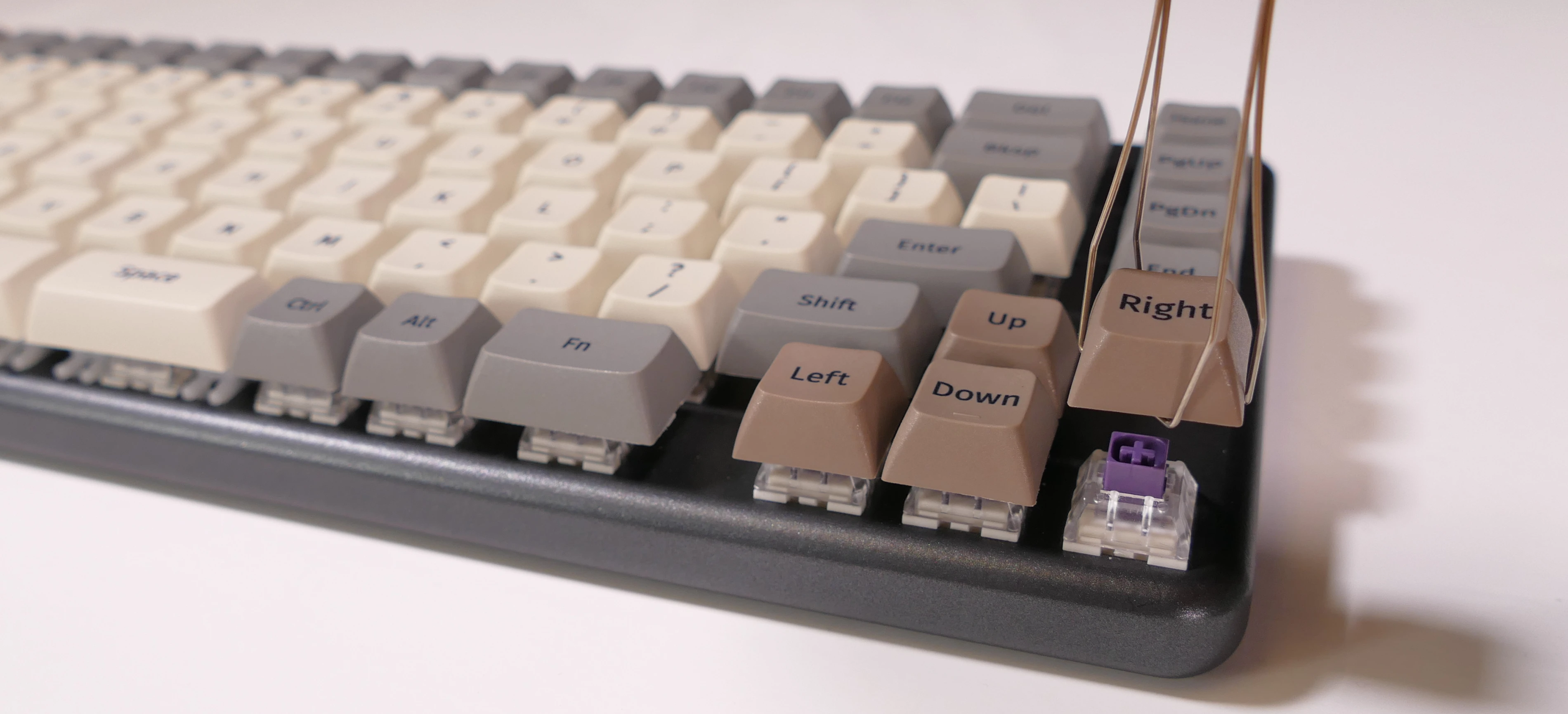
Removing larger keycaps:
- The included keycap puller works on all three of Launch's keycap sizes.
- The three 2U keycaps (both space bars and left shift) have stabilizers, so be sure to pull both sides evenly.
- These 2U keycaps take slightly more pulling force than the rest of the keycaps.
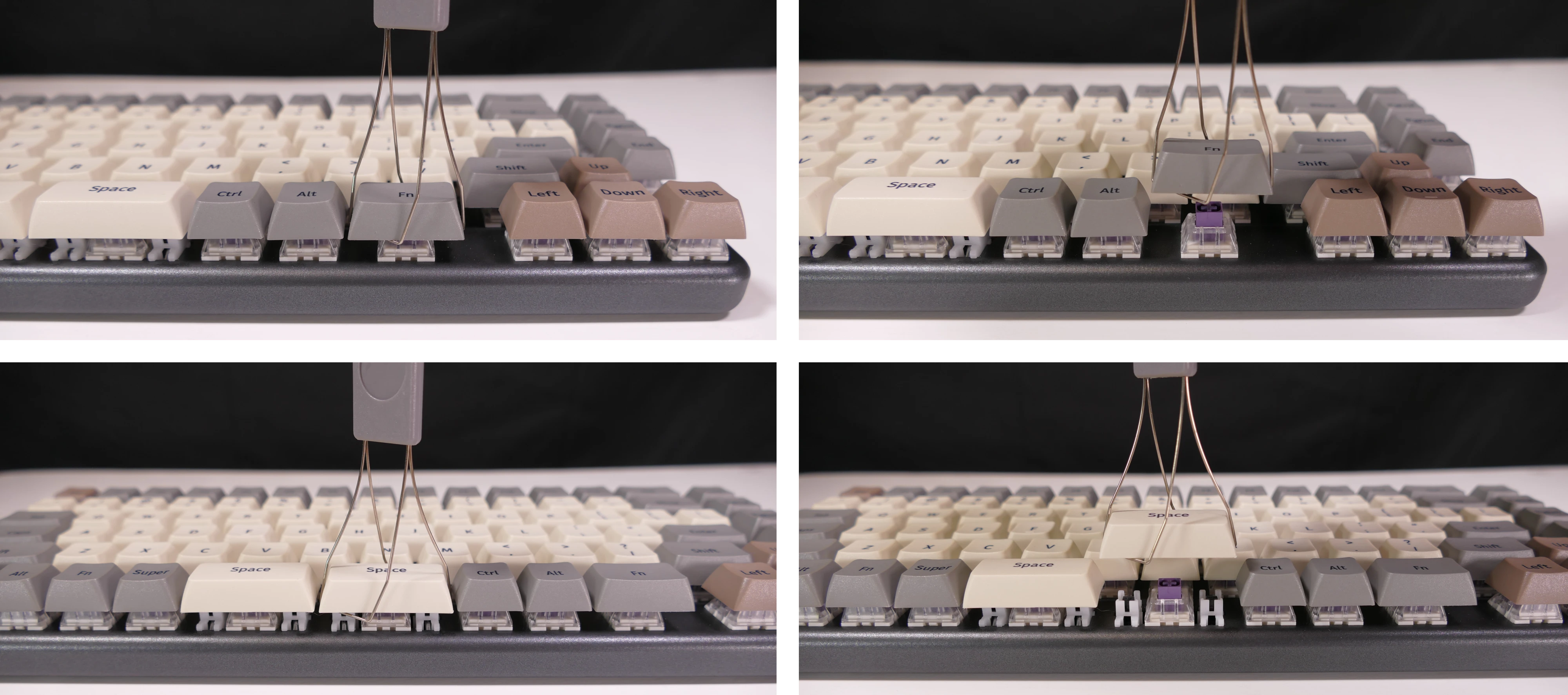
Steps to install a keycap:
- Position the keycap on top of the switch.
- Press the keycap down firmly until it's fully on the switch.
- The keycap will be held onto the switch by friction.
- The 2U keycaps with stabilizers require slightly more pressure to install.

Removing and installing switches:
Because Launch uses Kailh hot swap sockets, key switches can be removed and installed without soldering.
If you are changing all of the switches in your Launch, it is recommended to completely remove the PCB, install the switches into the top case without the PCB, then install the PCB into the case and onto the switch pins. This makes switch installation easier and reduces the likelihood of bending switch pins or damaging the PCB.
If you are installing new switches, ensure that the switches you're installing are compatible with surface-mount (SMD) LEDs.
Tools required: MX-style switch puller
Time estimate: ~1 minute per switch
Difficulty: Medium ●
Steps to remove a switch:
- Remove the keycap on the switch you wish to remove.
- Place the two tongs of the switch removal tool into the switch's locking tabs on the top and bottom edges of the switch.

- Pinch the tongs together to release the switch's locking clips from the chassis.
- Pull the switch upwards out of the socket.
- The switch's locking tabs can sometimes catch on the edges of the chassis cutouts. If the switch feels stuck, remove the tool and press the switch back down into place, then try removing it again.
- Switches take more force to remove than keycaps.

Steps to install a switch:
- Make sure the switch's pins are straight.
- If either of the pins is bent, gently bend it back into place.
- Caution: Attempting to install a switch with bent pins may damage the PCB and/or switch.
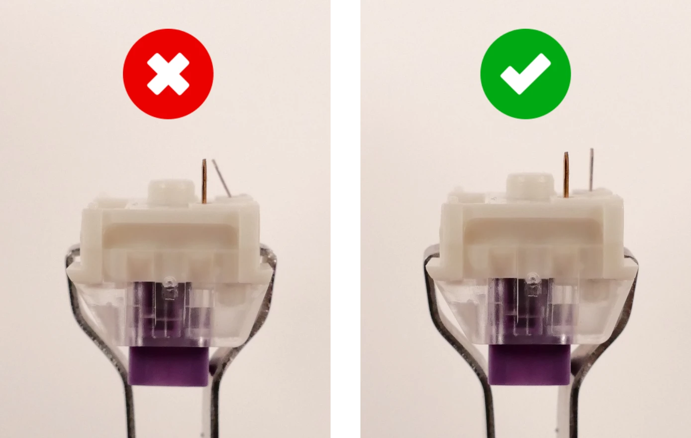
- Orient the switch so the clear LED window aligns with the LED on the PCB, near the top of the socket.
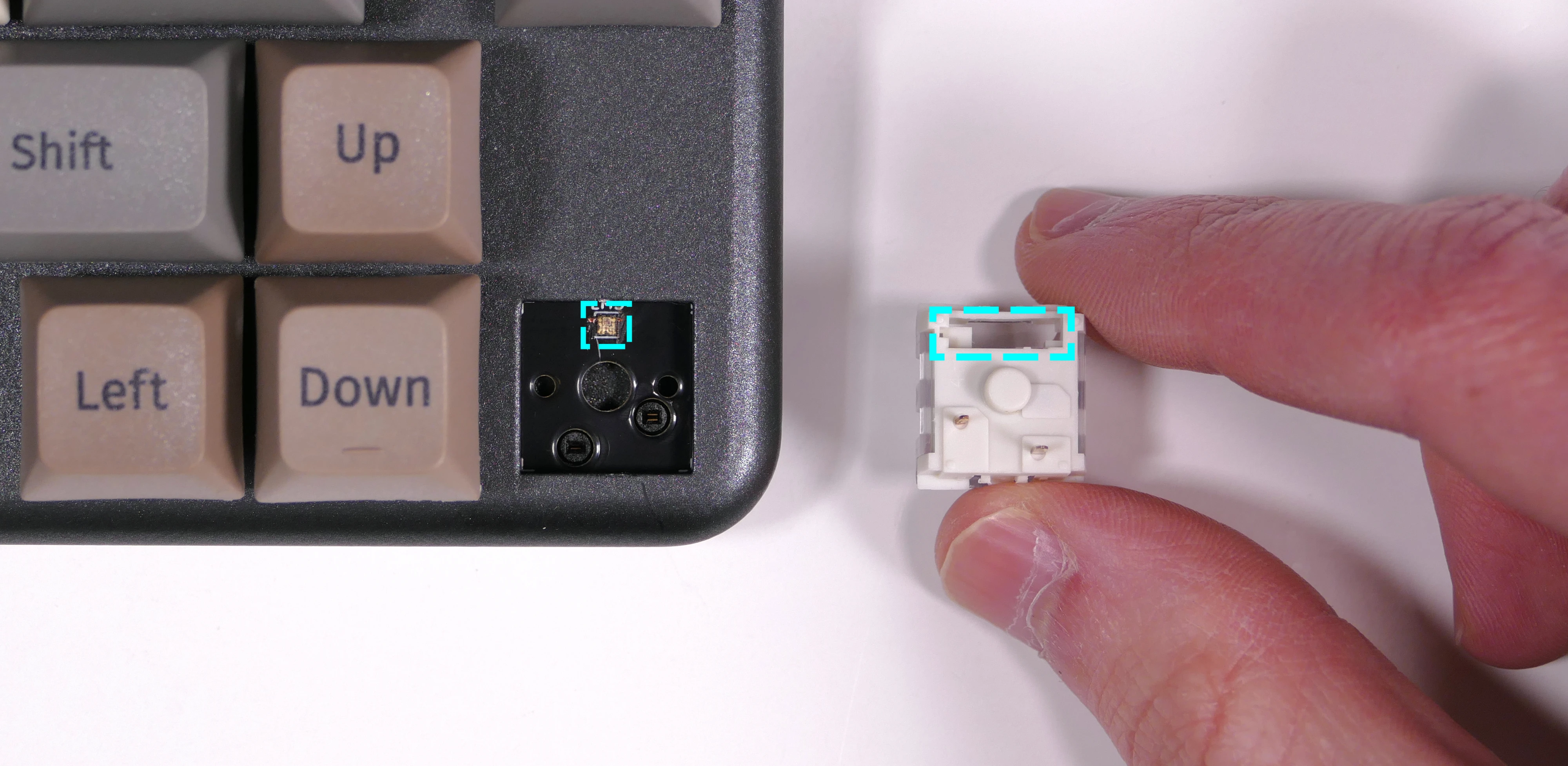
- Place the switch straight into the plate.
- Caution: Forcing the pins into the hot swap socket if the pins are not properly aligned could damage the PCB and/or switch.
- If you feel excessive resistance, pull the switch out, double-check that the pins are straight, and try installing the switch again.
- Once you feel the pins plug into the hot swap socket, press the switch down with more force to snap it into place within the chassis.

Removing the PCB:
Tools required: Keycap puller, MX-style switch puller, and cross-head (Phillips) screwdriver
Time estimate: 50 minutes
Difficulty: High ●
If the PCB in your Launch becomes damaged and needs to be replaced, or if you are changing all of the switches on the PCB, it can be removed and replaced using these instructions.
Steps to remove the PCB:
- Remove all of the keycaps and all of the switches.
- The 2U stabilizers do not need to be removed.
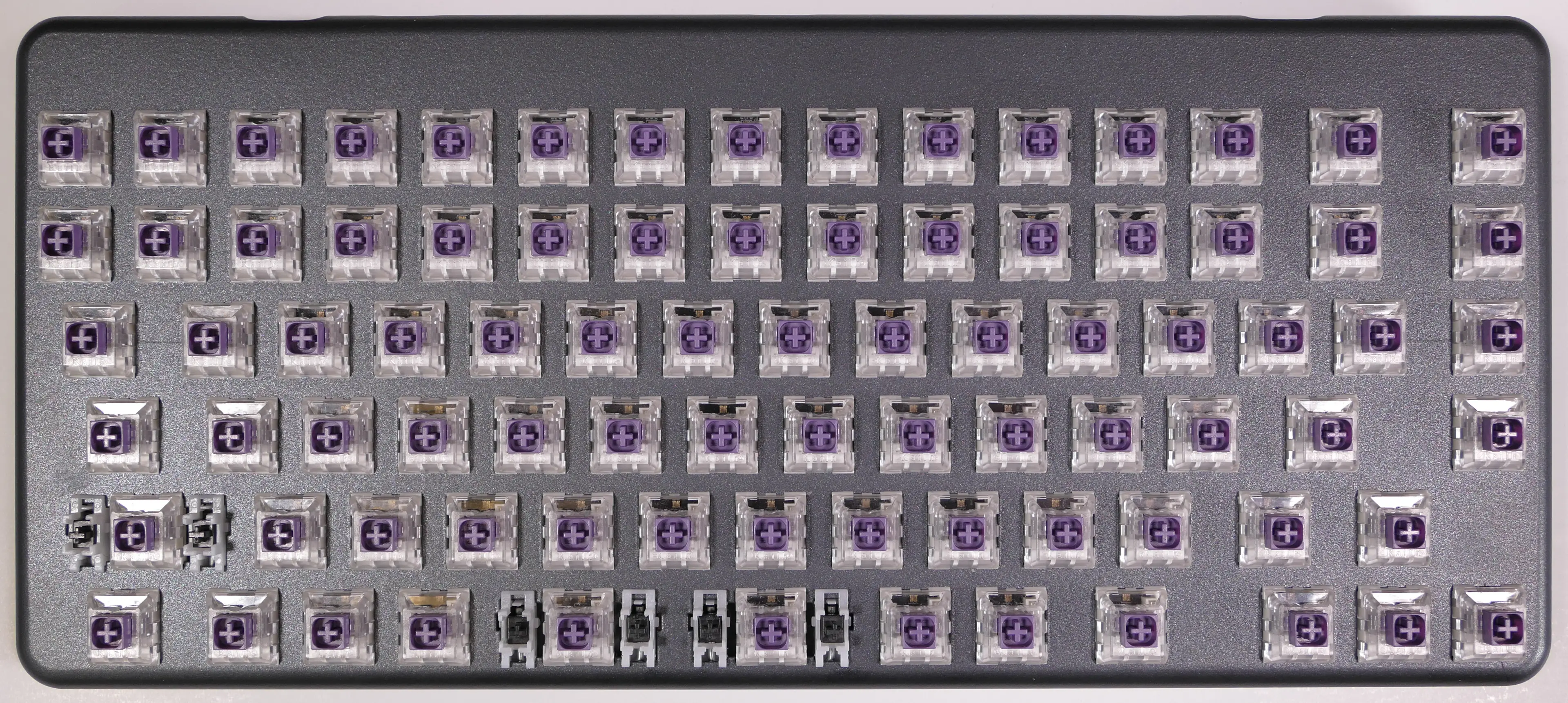
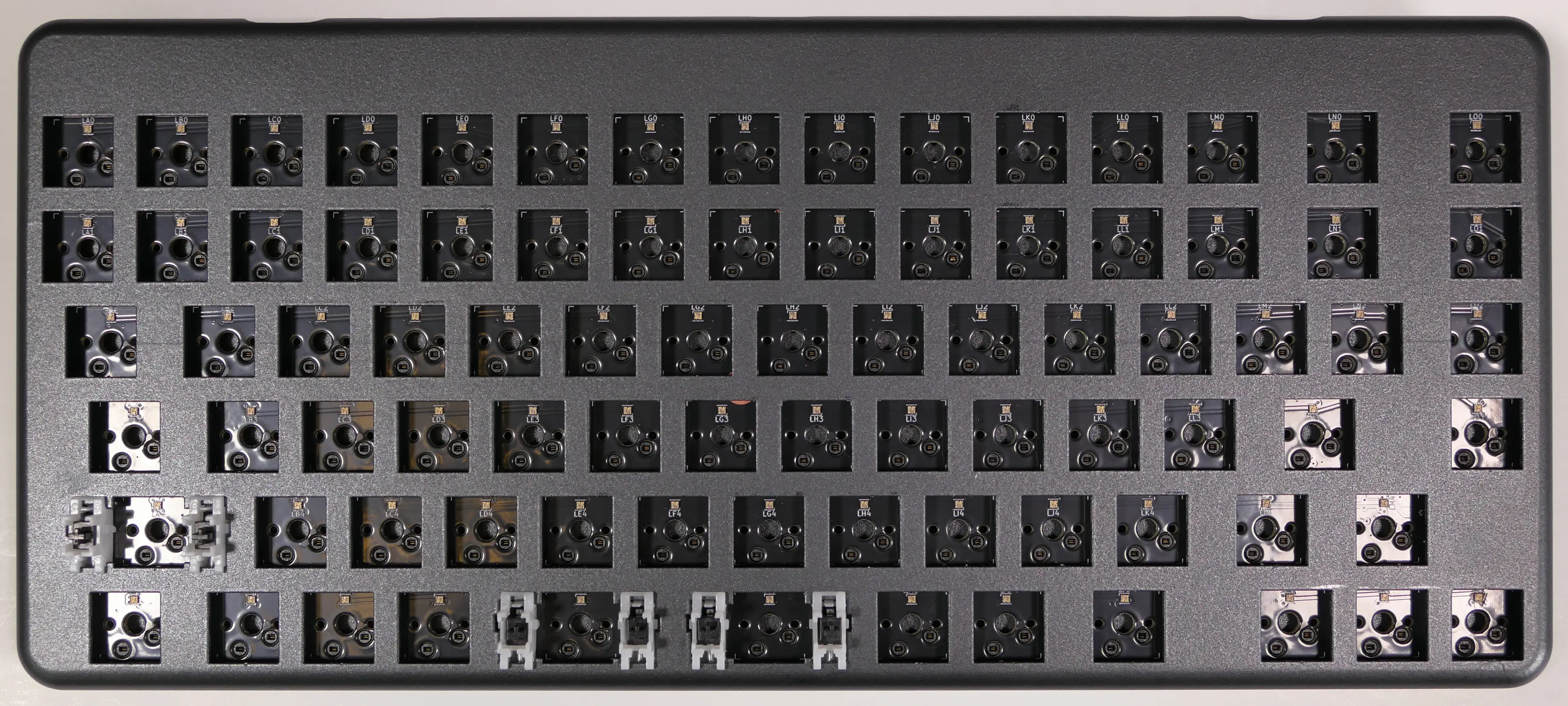
- Turn the keyboard over and remove the five bottom panel screws.
- The screws are set into adapters that may or may not come out with the screws.

- Remove the bottom panel.
- If the magnetic lift bar is installed, it can be used as a handle.
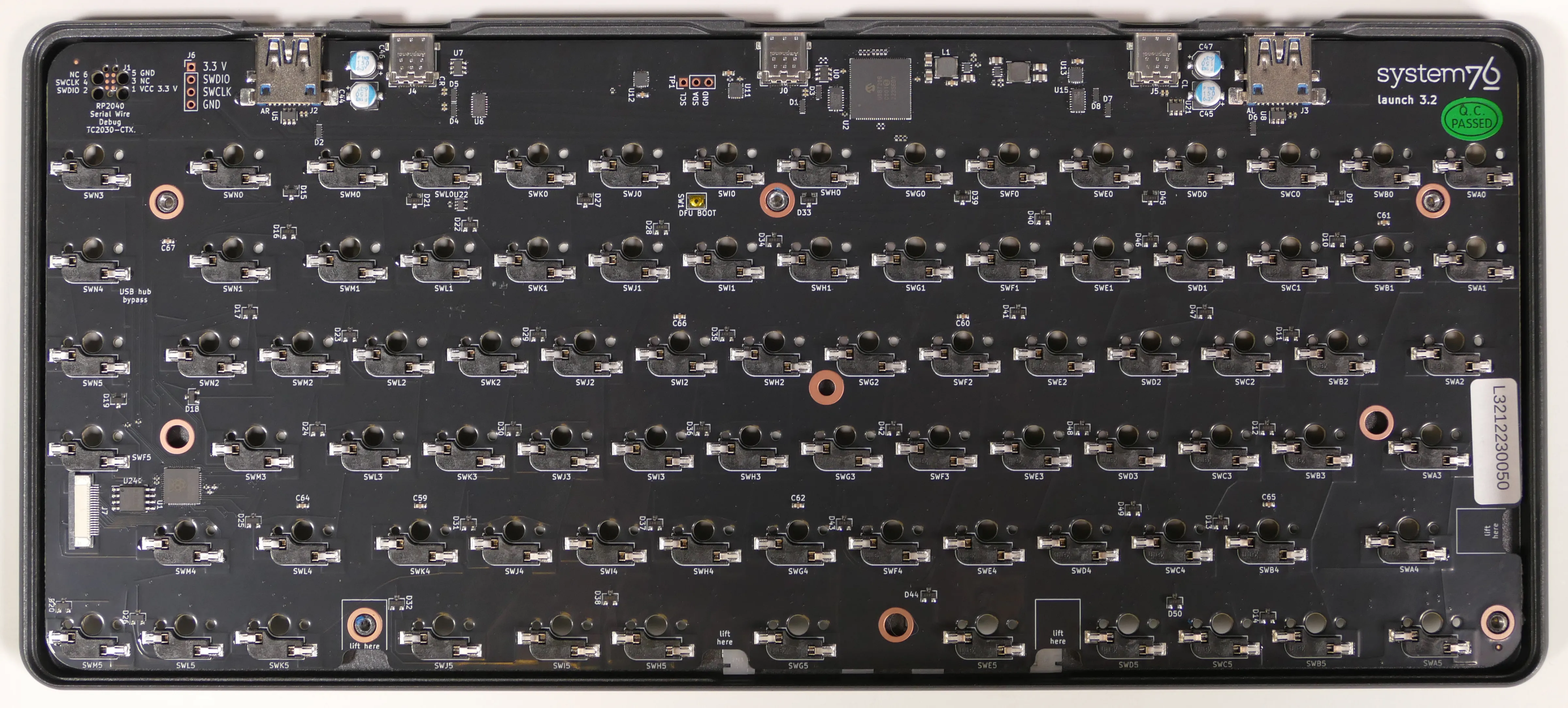
- Push the PCB up out of the chassis through one of the switch holes, then lift the PCB out of the chassis.
- To avoid the USB-C port catching on the chassis, push through one of the bottom row switch holes and lift the bottom edge of the PCB first.
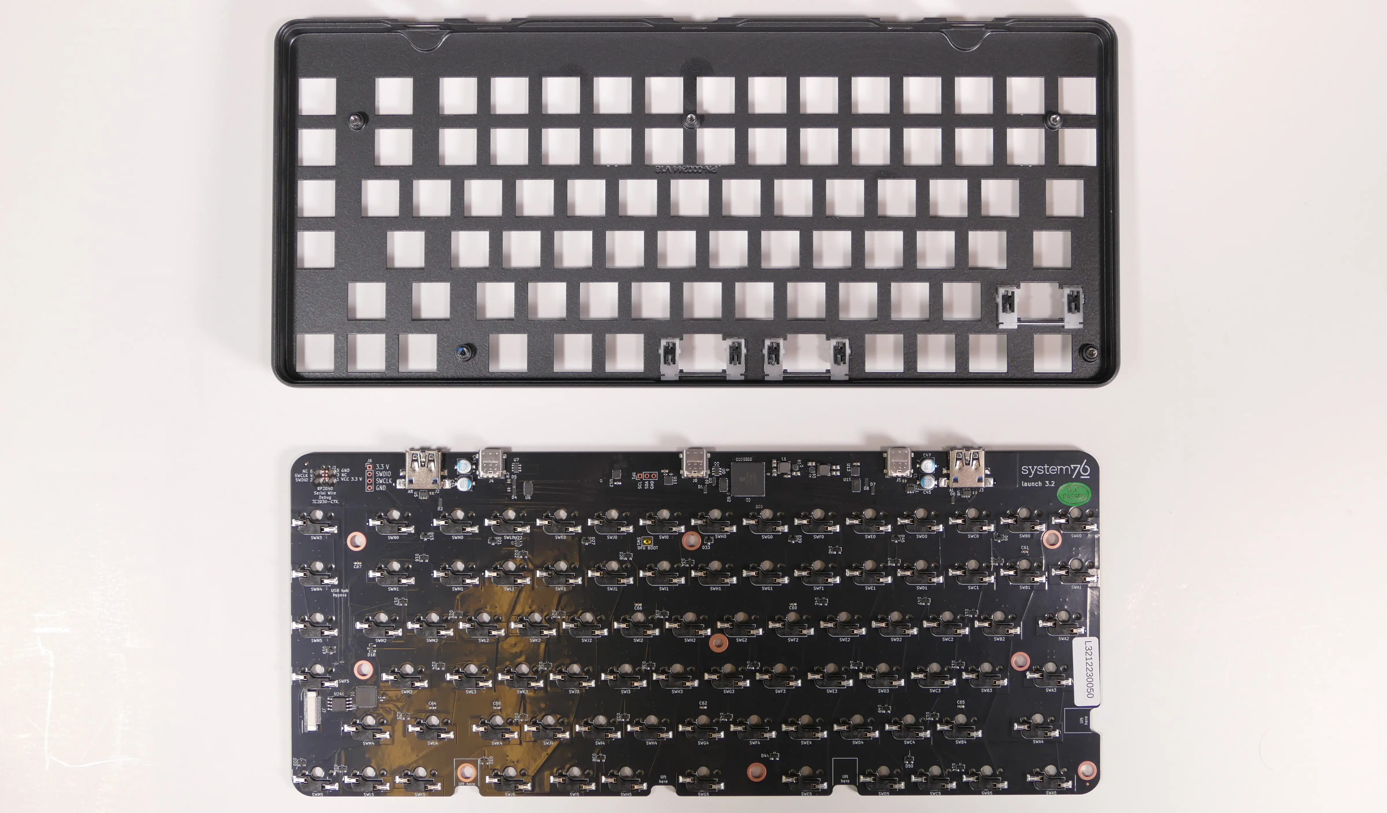
Steps to install the PCB:
- Install all of the switches into the chassis.
- The switches can also be installed after installing the PCB, but installing the switches first is recommended because it reduces the risk of individual bent pins damaging the PCB or switches during installation.
- Make sure the switches are in the correct orientation with the LED window at the top.
- The switches are not specific to their key/hole.
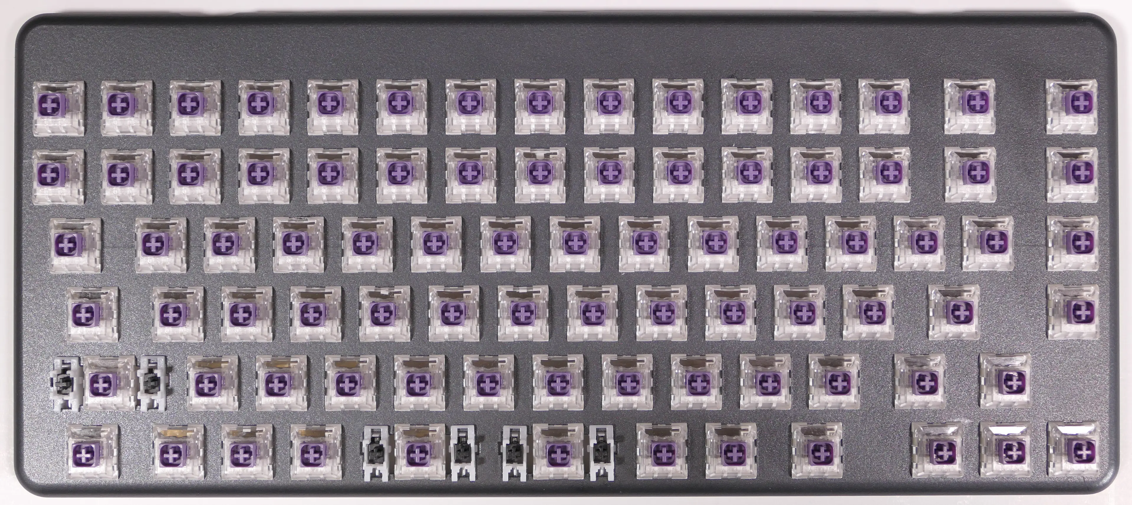
- Turn the chassis over and check that all of the switch pins are straight.
- Look down the rows of pins from the sides of the chassis to identify any bent pins.
- If any of the pins are bent when installing the PCB, the switch or the PCB may be damaged.
- In the image below, the pin marked with a red arrow is an example of a pin that is bent and needs to be straightened.
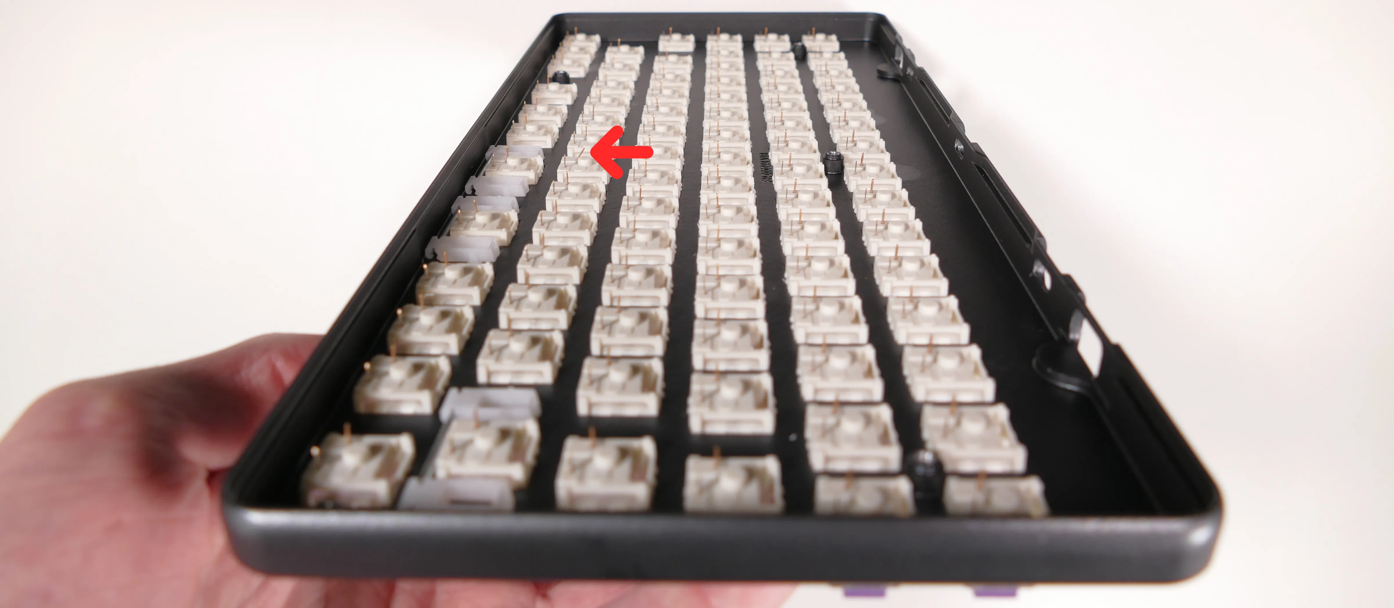
- Carefully line up the PCB with the switch pins and place it in the chassis, starting with the USB-C ports on the top edge.
- Evenly press the PCB down until all of the switch pins are fully seated in their sockets.
- It may help to pick up the keyboard and pinch to press both the PCB and the switches at the same time.
- If you feel excessive resistance, stop, remove the PCB, and ensure that all of the switch pins are lined up.
- The switch pins can be seen from the back of the sockets when they are fully seated, highlighted below.
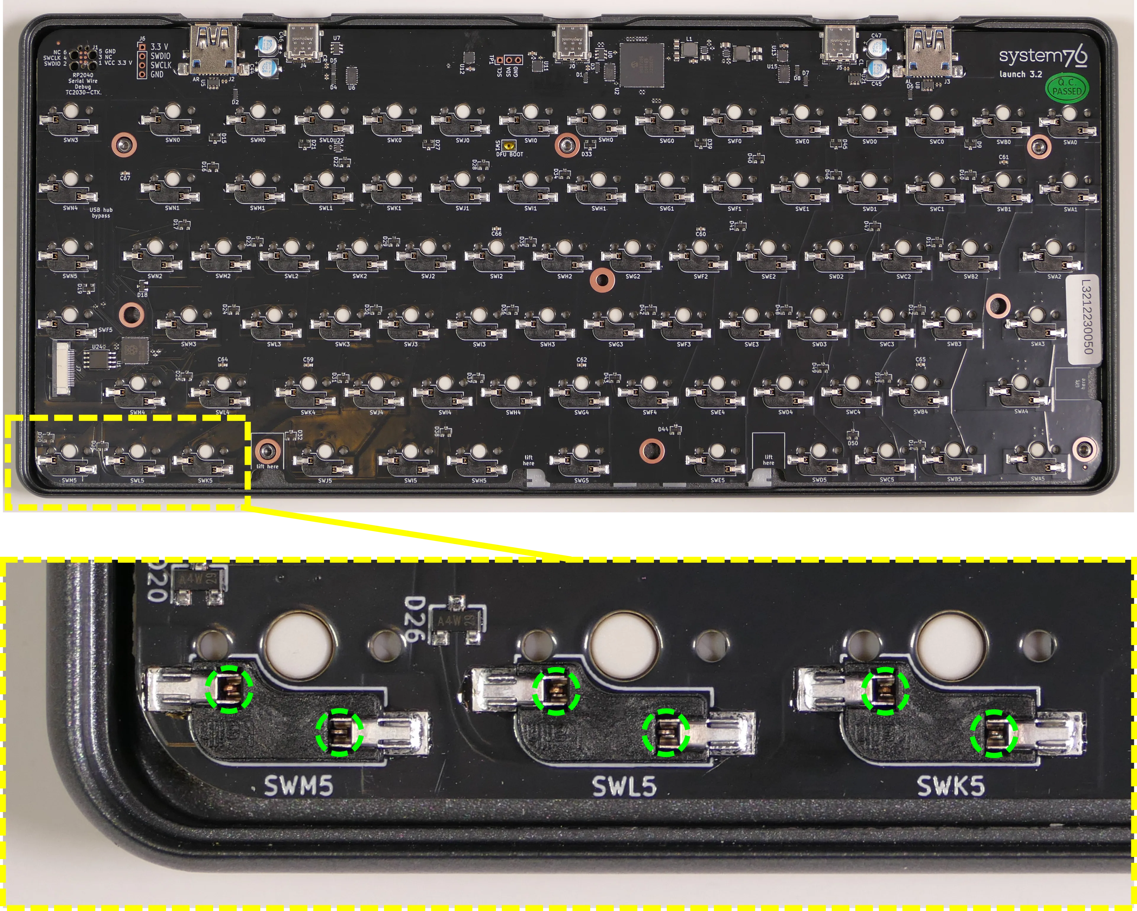
- Install the bottom cover and its four screws, flip the keyboard over, and put all of the keycaps back on.
- If any of the oval steel inserts came loose from the bottom cover, put them back into place before reinstalling the bottom cover.
- The steel inserts are held in with glue, but are also held in place magnetically if the magnetic lift bar is installed. They can be re-glued with CA glue.
- If any of the oval steel inserts came loose from the bottom cover, put them back into place before reinstalling the bottom cover.
Launch Heavy (launch_heavy_3)
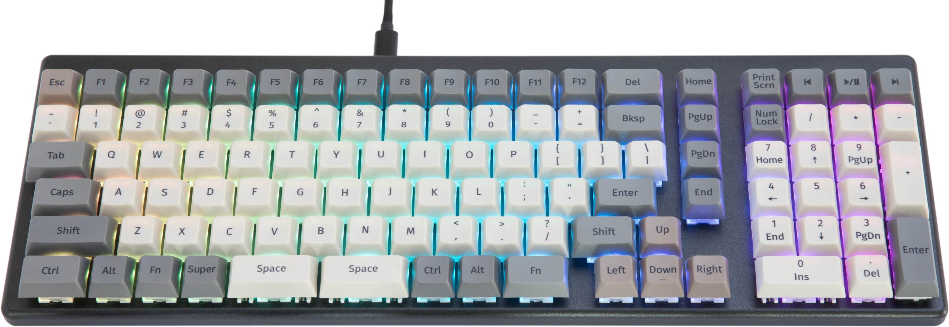
The System76 Launch Heavy is a configurable keyboard with the following specifications:
- Chassis
- Open-source milled chassis design
- Dual magnetically-attachable 15-degree angle lift bars
- Electronics
- Open-source main PCB design
- Revision 3.2
- Open-source numpad PCB design
- Revision 1.2
- Individually addressable RGB LED backlighting
- N-key rollover
- Open-source main PCB design
- Sockets and Switches
- Kailh MX hot swap sockets
- Default switch options:
- NovelKeys x Kailh Box Jade
- NovelKeys x Kailh Box Royal
- Kailh Box Silent Brown
- Kailh Box Silent Pink
- Keycaps
- PBT plastic
- Dye sublimated legend
- XDA profile
- Sizes:
- 6x 2U keycaps (both
Spacebars, leftShift, numpad0, numpad+, and numpadEnter)- All six 2U caps use plate-mount stabilizers
- 8x 1.5U keycaps (
Tab,Caps, leftCtrl, rightFn, rightShift,Enter,Bksp, andDel) - 91x 1U keycaps
- 6x 2U keycaps (both
- Layout
- Modified ANSI US QWERTY
- Custom Configurations
- Customize layout and lighting in firmware with the System76 Keyboard Configurator
- Available on Linux, Windows, and macOS
- Integrated Hub
- 2x USB 3.2 Gen 2 Type-C
- 2x USB 3.2 Gen 2 Type-A
- Firmware
- Included cables:
- 1x USB Type-C to USB Type-C
- 1x USB Type-C to USB Type-A
- Dimensions
- 39.40cm x 13.51cm x 3.03cm, 1315.42g
Launch Heavy (External Overview)
Top overview:

Back overview:

Box contents overview:

Launch Heavy (Customization & Repairs)
The Launch Heavy Configurable Keyboard can be customized and personalized in a variety of ways. It is recommended to unplug all USB cables and devices from your Launch Heavy before changing keycaps or switches.
- Connecting and using Launch Heavy
- Removing and installing keycaps
- Removing and installing switches
- Removing the PCBs
Connecting and using Launch Heavy:
- Connect the USB-C side of either the USB-C/USB-C or USB-C/USB-A cable to the Launch Heavy's center USB-C port.

- Connect the other side of the cable to your computer.
- Connect any other USB devices to the four downstream USB ports on either side of the Launch Heavy.
Removing and installing keycaps:
Launch Heavy uses only three sizes of uniform profile keycaps, which allows for a high degree of customization. Any two keycaps of the same size can be swapped on the keyboard, and several extras are included in the box.
Tools required: Keycap puller
Time estimate: 25 minutes (to replace all keycaps)
Difficulty: Easy ●
Steps to remove a keycap:
- Separate the two wire loops of the keycap puller and place them around two opposite corners of the keycap.
- The keycap puller can be partially inserted over the sides of the key first, then twisted to go over the corners.


- Pull slowly but firmly (directly away from the keyboard) until the keycap slides off of the switch's stem.

Removing larger keycaps:
- The included keycap puller works on all three of Launch Heavy's keycap sizes.
- The six 2U keycaps (both
Spacebars, leftShift, numpad0, numpad+, and numpadEnter) have stabilizers, so be sure to pull both sides evenly.- These 2U keycaps take slightly more pulling force than the rest of the keycaps.

Steps to install a keycap:
- Position the keycap on top of the switch.
- Press the keycap down firmly until it's fully on the switch.
- The keycap will be held onto the switch by friction.
- The 2U keycaps with stabilizers require slightly more pressure to install.

Removing and installing switches:
Launch Heavy uses Kailh hot swap sockets, so key switches can be removed and installed without soldering.
If you are changing all of the switches in your Launch Heavy, it is recommended to completely remove the PCBs, install the switches into the top case without the PCB, then install the PCBs into the case and onto the switch pins. This makes switch installation easier and reduces the likelihood of bending switch pins or damaging the PCBs.
If you are installing new switches, ensure that the switches you're installing are compatible with surface-mount (SMD) LEDs.
Tools required: MX-style switch puller
Time estimate: ~1 minute per switch
Difficulty: Medium ●
Steps to remove a switch:
- Remove the keycap on the switch you wish to remove.
- Place the two tongs of the switch removal tool into the switch's locking tabs on the top and bottom edges of the switch.
- For the vertical keys on the numpad, the locking tabs are on the left and right edges of the switch.

- Pinch the tongs together to release the switch's locking clips from the chassis.
- Pull the switch upwards out of the socket.
- The switch's locking tabs can sometimes catch on the edges of the chassis cutouts. If the switch feels stuck, remove the tool and press the switch back down into place, then try removing it again.
- Switches take more force to remove than keycaps.

Steps to install a switch:
- Make sure the switch's pins are straight.
- If either of the pins is bent, gently bend it back into place.
- Caution: Attempting to install a switch with bent pins may damage the PCB and/or switch.

- Orient the switch so the clear LED window aligns with the LED on the PCB.
- For the two vertical keys on the numpad, the LED window goes on the right.
- For all other switches, the LED window goes on the top.

- Place the switch straight into the plate.
- Caution: Forcing the pins into the hot swap socket if the pins are not properly aligned could damage the PCB and/or switch.
- If you feel excessive resistance, pull the switch out, double-check that the pins are straight, and try installing the switch again.
- Once you feel the pins plug into the hot swap socket, press the switch down with more force to snap it into place within the chassis.

Removing the PCBs:
Tools required: Keycap puller, MX-style switch puller, and cross-head (Phillips) screwdriver
Time estimate: 50 minutes
Difficulty: High ●
If either of the PCBs in your Launch Heavy become damaged and need to be replaced, or if you are changing all of the switches in the keyboard, they can be removed and replaced using these instructions. The two PCBs are joined by a 100mm long, 20 pin, 0.5mm pitch FPC cable.
Steps to remove the PCBs:
- Remove all of the keycaps and all of the switches.
- The 2U stabilizers do not need to be removed.


- Turn the keyboard over and remove the eight bottom panel screws.
- The screws are set into adapters that may or may not come out with the screws.

- Remove the bottom panel.
- If the magnetic lift bars are installed, they can be used as handles.

- Disconnect and remove the flat ribbon cable between the main PCB (
launch 3.2) and the numpad PCB (launch_heavy 1.2).- Slide the black latches away from the white connectors to free the cable.
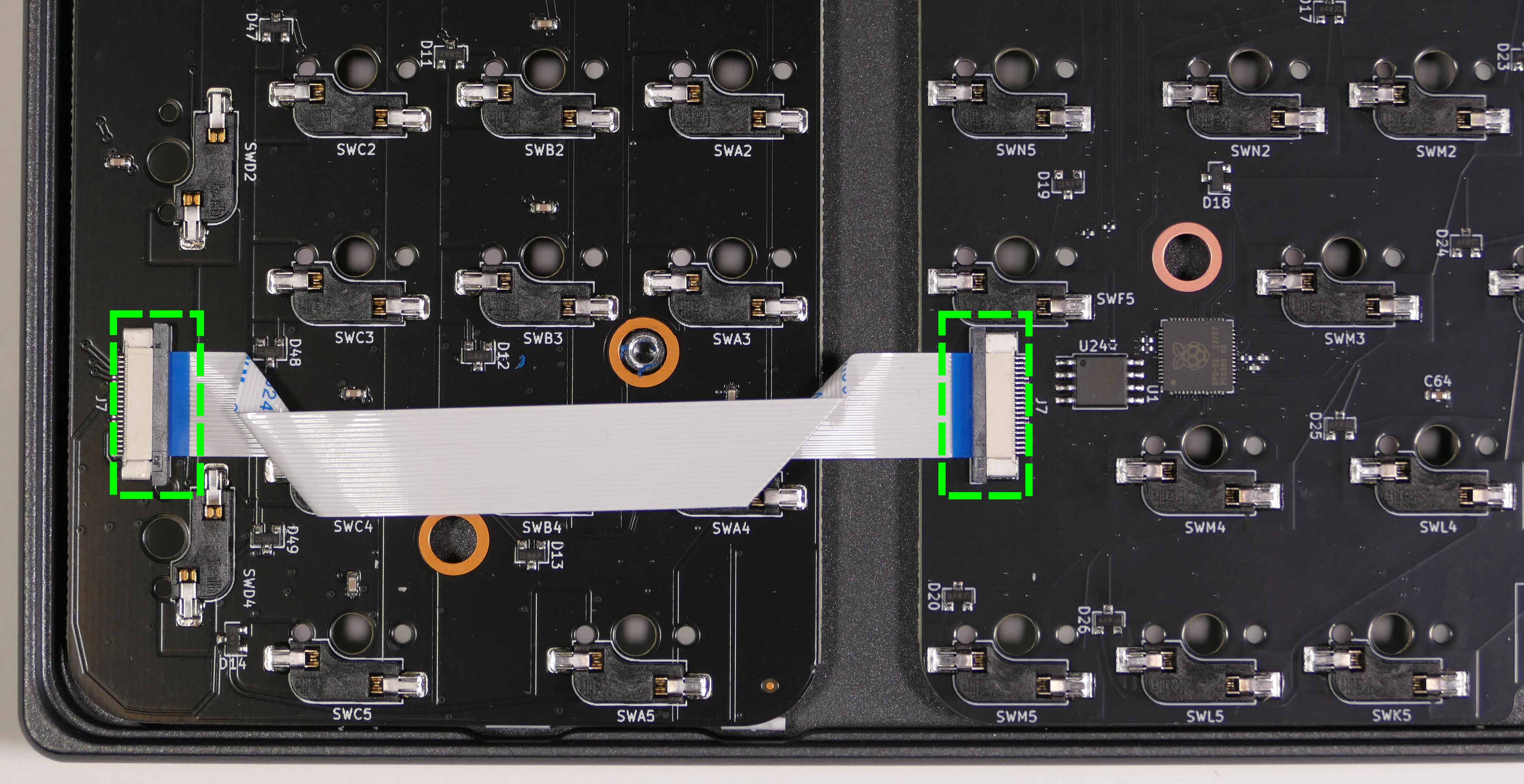
- Push each PCB up out of the chassis through one of the switch holes, then lift each PCB out of the chassis, one at a time.
- For the main board, to avoid the USB-C port catching on the chassis, push through one of the bottom row switch holes and lift the bottom edge of the PCB first.
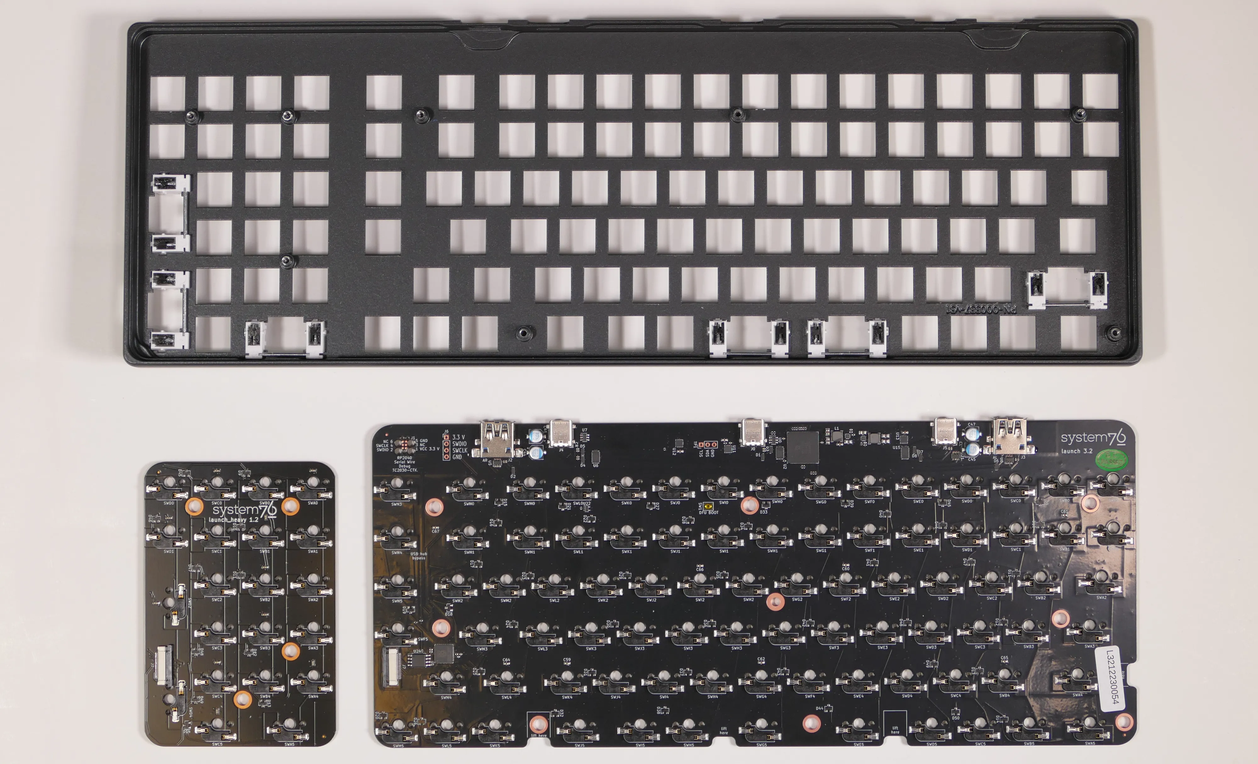
Steps to install the PCBs:
- Install all of the switches into the chassis.
- The switches can also be installed after installing the PCBs, but installing the switches first is recommended because it reduces the risk of individual bent pins damaging the PCBs or switches during installation.
- Make sure the switches are in the correct orientation.
- For the two vertical keys on the numpad (highlighted red below), the LED window goes on the right.
- For all other switches, the LED window goes on the top.
- The switches are not specific to their key/hole.

- Turn the chassis over and check that all of the switch pins are straight.
- Look down the rows of pins from the sides of the chassis to identify any bent pins.
- If any of the pins are bent when installing the PCBs, the switch or corresponding PCB may be damaged.
- In the image below, the pin marked with a red arrow is an example of a pin that is bent and needs to be straightened.

- Carefully line up the main PCB with the switch pins and place it in the chassis, starting with the USB-C port on the top edge.
- Evenly press the PCB down until all of the switch pins are fully seated in their sockets.
- It may help to pick up the keyboard and pinch to press both the PCB and the switches at the same time.
- If you feel excessive resistance, stop, remove the PCB, and ensure that all of the switch pins are lined up.
- The switch pins can be seen from the back of the sockets when they are fully seated, highlighted below.

- Repeat the previous step for the numpad PCB.
- Insert the ribbon cable into the white connector on both PCBs, then slide the black latches shut.
- The ribbon should bend downwards from the connectors, so as not to obstruct the screw hole in the numpad PCB.
- Install the bottom cover and its four screws, flip the keyboard over, and put all of the keycaps back on.
- If any of the oval steel inserts came loose from the bottom cover, put them back into place before reinstalling the bottom cover.
- The steel inserts are held in with glue, but are also held in place magnetically if the magnetic lift bar is installed. They can be re-glued with CA glue.
- If any of the oval steel inserts came loose from the bottom cover, put them back into place before reinstalling the bottom cover.
Launch Lite (launch_lite_1)

The System76 Launch Lite is a configurable keyboard with the following specifications:
- Chassis
- Open-source milled chassis design
- Magnetically-attachable 15-degree angle lift bar
- Electronics
- Open-source PCB design
- Individually addressable RGB LED backlighting
- N-key rollover
- Sockets and Switches
- Kailh MX hot swap sockets
- Default switch options:
- NovelKeys x Kailh Box Jade
- NovelKeys x Kailh Box Royal
- Kailh Box Silent Brown
- Kailh Box Silent Pink
- Keycaps
- PBT plastic
- Dye sublimated legend
- XDA profile
- Sizes:
- 3x 2U keycaps (both
Spacebars and leftShift)- All three 2U caps use plate-mount stabilizers
- 7x 1.5U keycaps (
Tab,Caps, leftCtrl, rightFn, rightShift,Enter, andBksp) - 60x 1U keycaps
- 3x 2U keycaps (both
- Layout
- Modified ANSI US QWERTY
- Custom Configurations
- Customize layout and lighting in firmware with the System76 Keyboard Configurator
- Available on Linux, Windows, and macOS
- Firmware
- Included cables:
- 1x USB Type-C to USB Type-C
- 1x USB Type-C to USB Type-A
- Dimensions
- 30.83cm x 10.71cm x 3.06cm, 816.46g
Launch Lite (External Overview)
Top overview:
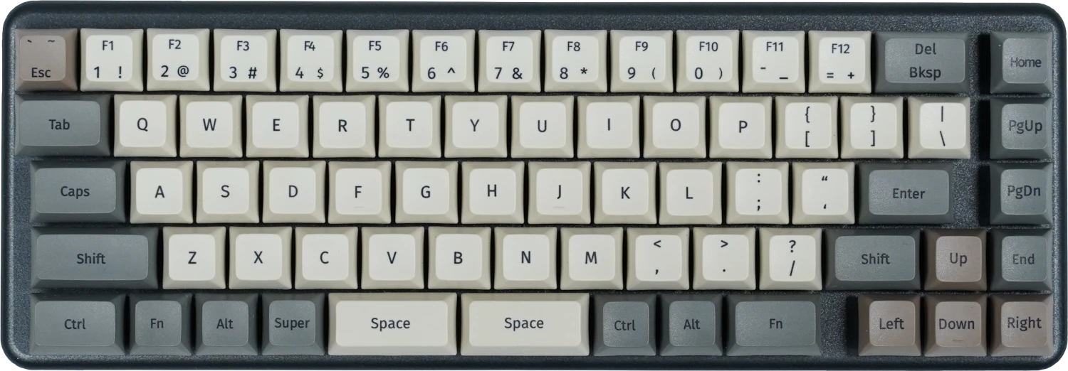
Back overview:

Box contents overview:
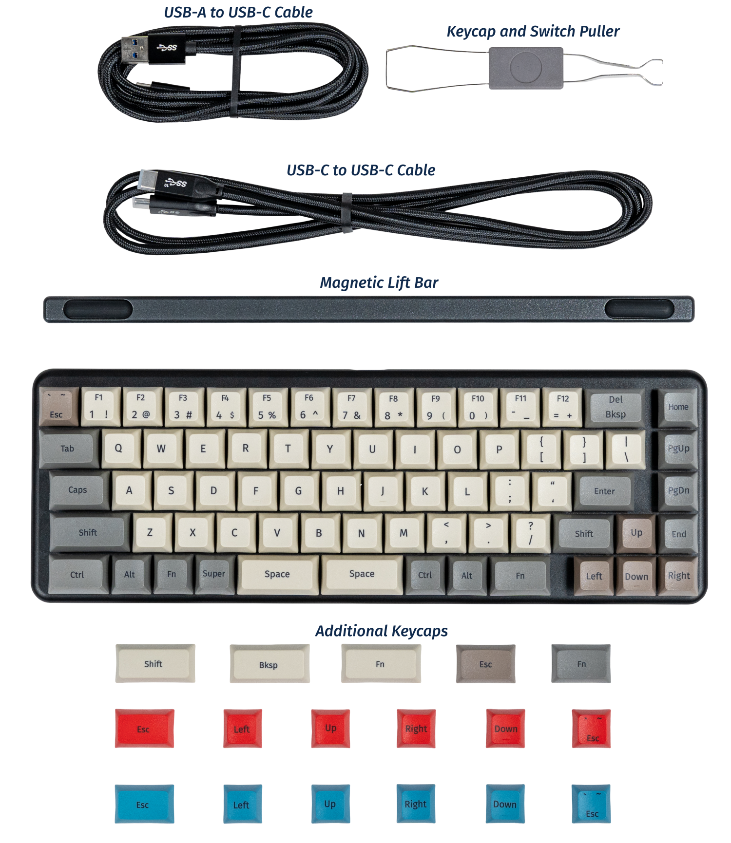
- Contact System76 Support to purchase replacement accessories (availability may vary.)
Launch Lite (Customization & Repairs)
The Launch Lite Configurable Keyboard can be customized and personalized in a variety of ways. It is recommended to unplug all USB cables and devices from your Launch before changing keycaps or switches.
- Connecting and using Launch Lite
- Removing and installing keycaps
- Removing and installing switches
- Removing the PCB
Connecting and using Launch Lite:

- Connect the USB-C side of either the USB-C/USB-C or USB-C/USB-A cable to the Launch Lite's USB-C port, shown above.
- Connect the other side of the cable to your computer.
Removing and installing keycaps:
Launch Lite uses only three sizes of uniform profile keycaps, which allows for a high degree of customization. Any two keycaps of the same size can be swapped on the keyboard, and several extras are included in the box.
Tools required: Keycap puller
Time estimate: 20 minutes (to replace all keycaps)
Difficulty: Easy ●
Steps to remove a keycap:
- Separate the two wire loops of the keycap puller and place them around two opposite corners of the keycap.
- The keycap puller can be partially inserted over the sides of the key first, then twisted to go over the corners.


- Pull slowly but firmly (directly away from the keyboard) until the keycap slides off of the switch's stem.

Removing larger keycaps:
- The included keycap puller works on all three of Launch Lite's keycap sizes.
- The three 2U keycaps (both space bars and left shift) have stabilizers, so be sure to pull both sides evenly.
- These 2U keycaps take slightly more pulling force than the rest of the keycaps.

Steps to install a keycap:
- Position the keycap on top of the switch.
- Press the keycap down firmly until it's fully on the switch.
- The keycap will be held onto the switch by friction.
- The 2U keycaps with stabilizers require slightly more pressure to install.

Removing and installing switches:
Because Launch Lite uses Kailh hot swap sockets, key switches can be removed and installed without soldering.
If you are changing all of the switches in your Launch Lite, it is recommended to completely remove the PCB, install the switches into the top case without the PCB, then install the PCB into the case and onto the switch pins. This makes switch installation easier and reduces the likelihood of bending switch pins or damaging the PCB.
If you are installing new switches, ensure that the switches you're installing are compatible with surface-mount (SMD) LEDs.
Tools required: MX-style switch puller
Time estimate: ~1 minute per switch
Difficulty: Medium ●
Steps to remove a switch:
- Remove the keycap on the switch you wish to remove.
- Place the two tongs of the switch removal tool into the switch's locking tabs on the top and bottom edges of the switch.

- Pinch the tongs together to release the switch's locking clips from the chassis.
- Pull the switch upwards out of the socket.
- The switch's locking tabs can sometimes catch on the edges of the chassis cutouts. If the switch feels stuck, remove the tool and press the switch back down into place, then try removing it again.
- Switches take more force to remove than keycaps.

Steps to install a switch:
- Make sure the switch's pins are straight.
- If either of the pins is bent, gently bend it back into place.
- Caution: Attempting to install a switch with bent pins may damage the PCB and/or switch.

- Orient the switch so the clear LED window aligns with the LED on the PCB, near the top of the socket.

- Place the switch straight into the plate.
- Caution: Forcing the pins into the hot swap socket if the pins are not properly aligned could damage the PCB and/or switch.
- If you feel excessive resistance, pull the switch out, double-check that the pins are straight, and try installing the switch again.
- Once you feel the pins plug into the hot swap socket, press the switch down with more force to snap it into place within the chassis.

Removing the PCB:
Tools required: Keycap puller, MX-style switch puller, and cross-head (Phillips) screwdriver
Time estimate: 50 minutes
Difficulty: High ●
If the PCB in your Launch becomes damaged and needs to be replaced, or if you are changing all of the switches on the PCB, it can be removed and replaced using these instructions.
Steps to remove the PCB:
- Remove all of the keycaps and all of the switches.
- The 2U stabilizers do not need to be removed.


- Turn the keyboard over and remove the four bottom panel screws.
- The screws are set into adapters that may or may not come out with the screws.

- Remove the bottom panel.
- If the magnetic lift bar is installed, it can be used as a handle.
- A small plastic spacer (highlighted cyan below) may come loose; if it does, place it back in the middle PCB hole.

- Push the PCB up out of the chassis through one of the switch holes, then lift the PCB out of the chassis.
- To avoid the USB-C port catching on the chassis, push through one of the bottom row switch holes and lift the bottom edge of the PCB first.

Steps to install the PCB:
- Install all of the switches into the chassis.
- The switches can also be installed after installing the PCB, but installing the switches first is recommended because it reduces the risk of individual bent pins damaging the PCB or switches during installation.
- Make sure the switches are in the correct orientation with the LED window at the top.
- The switches are not specific to their key/hole.

- Turn the chassis over and check that all of the switch pins are straight.
- Look down the rows of pins from the sides of the chassis to identify any bent pins.
- If any of the pins are bent when installing the PCB, the switch or the PCB may be damaged.
- In the image below, the pin marked with a red arrow is an example of a pin that is bent and needs to be straightened.

- Carefully line up the PCB with the switch pins and place it in the chassis, starting with the USB-C port on the top edge.
- Evenly press the PCB down until all of the switch pins are fully seated in their sockets.
- It may help to pick up the keyboard and pinch to press both the PCB and the switches at the same time.
- If you feel excessive resistance, stop, remove the PCB, and ensure that all of the switch pins are lined up.
- The switch pins can be seen from the back of the sockets when they are fully seated, highlighted below.

- Install the bottom cover and its four screws, flip the keyboard over, and put all of the keycaps back on.
- If any of the oval magnets came loose from the bottom cover, put them back into place before reinstalling the bottom cover.
- The magnets are held in by glue, but are also held in place magnetically if the magnetic lift bar is installed.
- If any of the oval magnets came loose from the bottom cover, put them back into place before reinstalling the bottom cover.
Lemur Pro (lemp13)
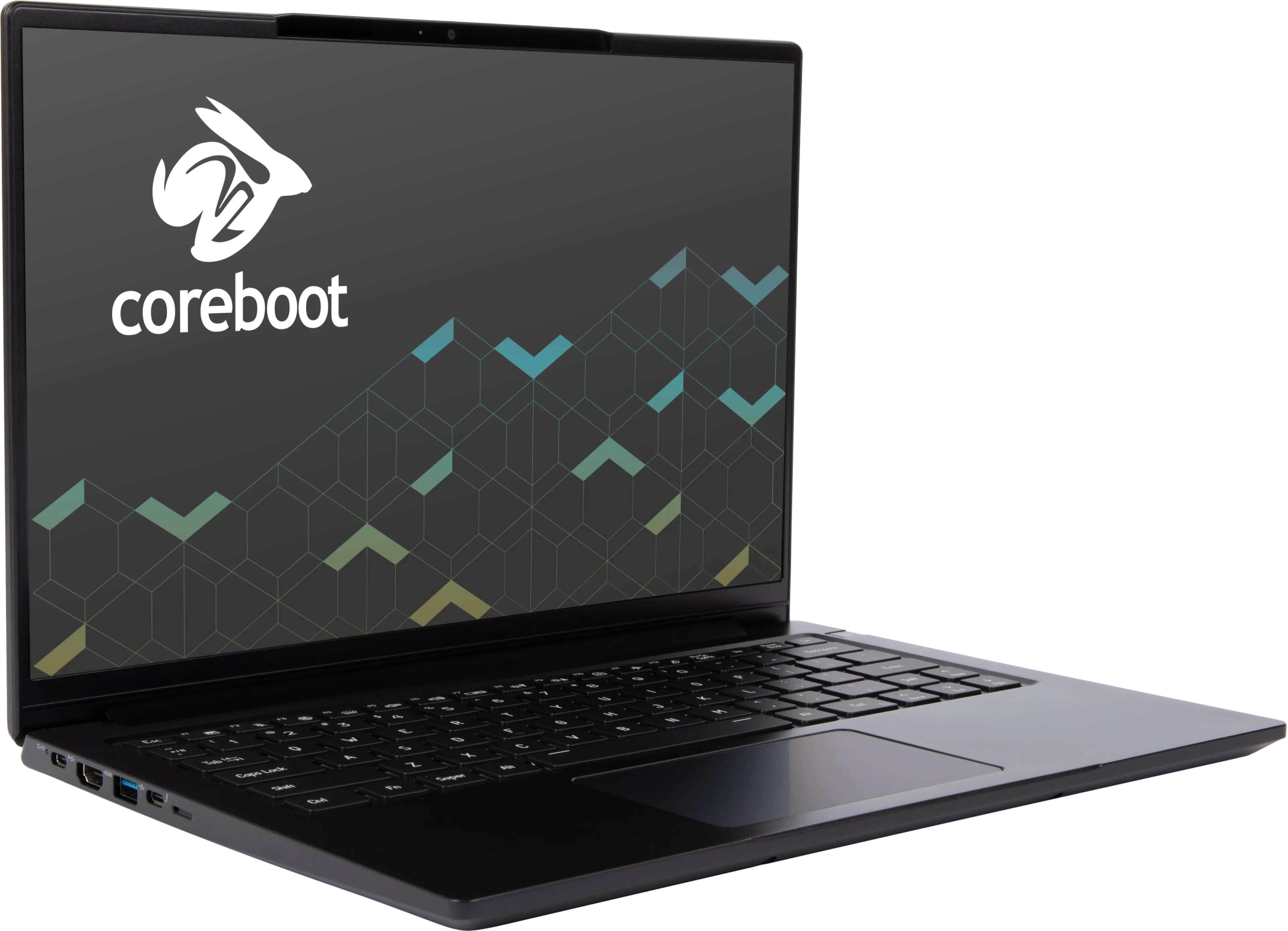
The System76 Lemur Pro is a laptop with the following specifications:
- CPU
- Supports Intel Core Ultra 1st generation (Meteor Lake) CPUs
- BIOS
- XMC XM25QU256C flash chip
- WSON-8 form factor
- Programmed with System76 Open Firmware
- XMC XM25QU256C flash chip
- EC
- ITE IT5570E
- Programmed with System76 EC
- Graphics
- GPU: Intel Iris Xe Graphics
- GOP driver is recommended, VBT is provided
- eDP display: 14.0" 1920x1200@60Hz LCD
- LCD panel options:
- Tianma TM140VDHP21
- Brightness: 400 nits (cd/m²)
- sRGB color coverage: 100%
- BOE NE140WUM-N6F
- Brightness: 400 nits (cd/m²)
- sRGB color coverage: 100%
- ...or other equivalent
- Tianma TM140VDHP21
- LCD panel options:
- External video outputs:
- 1x HDMI 2.1
- 1x DisplayPort 1.4 over USB-C
- GPU: Intel Iris Xe Graphics
- Memory
- Channel 0: 8-GB on-board DDR5
- 4x Samsung K4RAH165VB-BCQK (2GB each)
- Channel 1: 8-GB/16-GB/32-GB/48-GB DDR5 SO-DIMM @ 4800 MHz
- Channel 0: 8-GB on-board DDR5
- Networking
- M.2 PCIe/CNVi WiFi/Bluetooth options:
- Intel Wi-Fi 7 BE200
- Bluetooth 5.4
- Intel Wi-Fi 6E AX210/AX211
- Bluetooth 5.3
- Intel Wi-Fi 7 BE200
- M.2 PCIe/CNVi WiFi/Bluetooth options:
- Power
- 20V, 3.25A (65W) DC-in
- Power input via either USB-C port
- Included AC adapter: Chicony A20-065N3A
- AC power cord type: IEC C5
- 73Wh 4-cell Lithium-Ion battery
- Model number: L240BAT-4-73
- 20V, 3.25A (65W) DC-in
- Sound
- Intel Meteor Lake-P HD Audio Controller
- Realtek ALC245 audio codec
- Internal speakers & microphone
- 3.5mm headphone/microphone combo jack
- HDMI, USB-C DisplayPort audio
- Intel Meteor Lake-P HD Audio Controller
- Storage
- 2x M.2 (PCIe NVMe Gen 4)
- MicroSD card reader (OZ711LV2)
- USB
- 1x USB Type-C with Thunderbolt 4
- Supports DisplayPort over USB-C
- Supports USB-C charging (USB-PD)
- 1x USB 3.2 Gen 2 Type-C
- Supports USB-C charging (USB-PD)
- 1x USB 3.2 Gen 2 Type-A
- 1x USB 3.2 Gen 1 Type-A
- 1x USB Type-C with Thunderbolt 4
- Dimensions
- 1.7cm x 31.2cm x 22.3cm, 0.998kg
Lemur Pro (External Overview)
Left side:

Right side:

Front side:
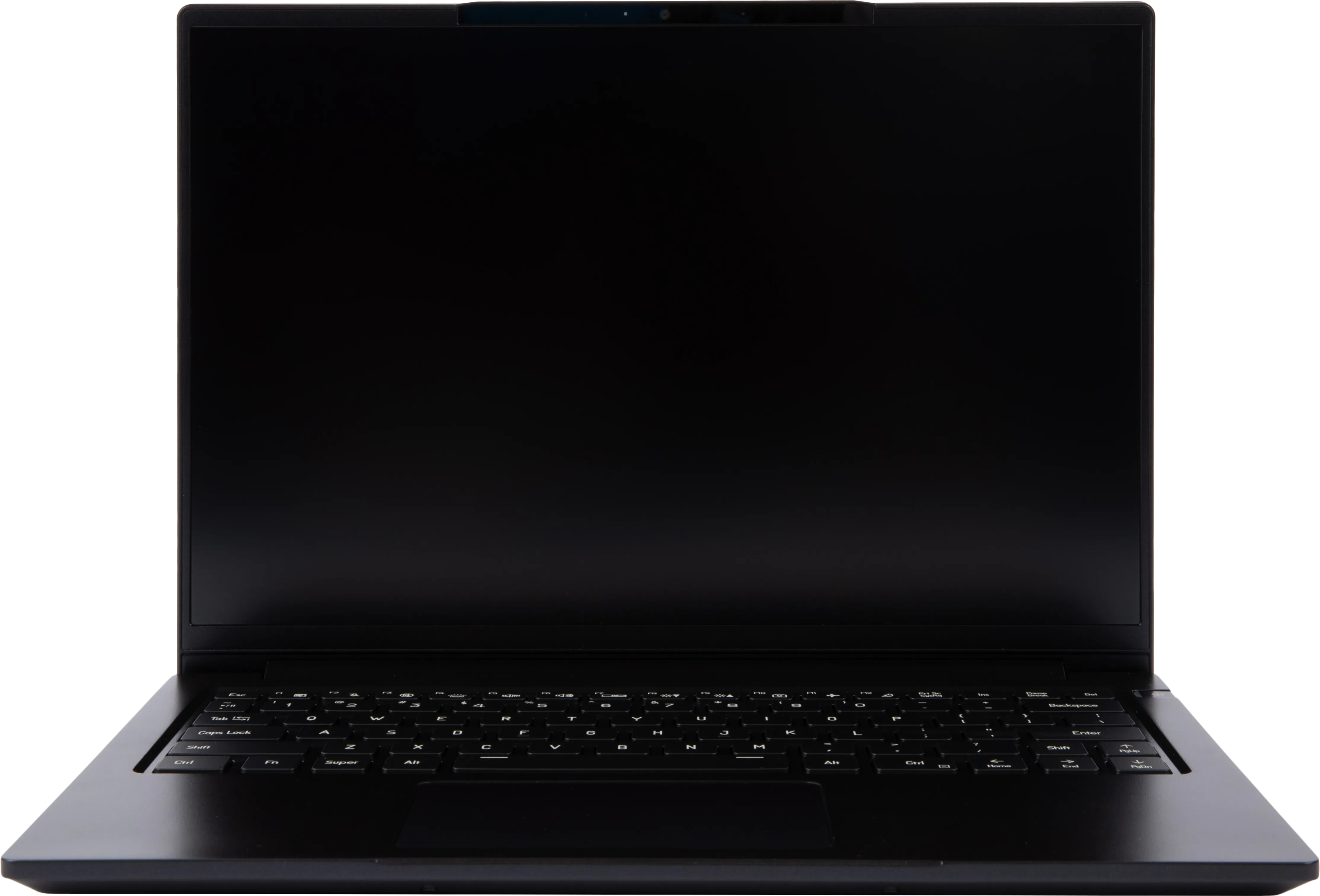
Back side:

Keyboard & touchpad:
Before May 2024 (lemp13):
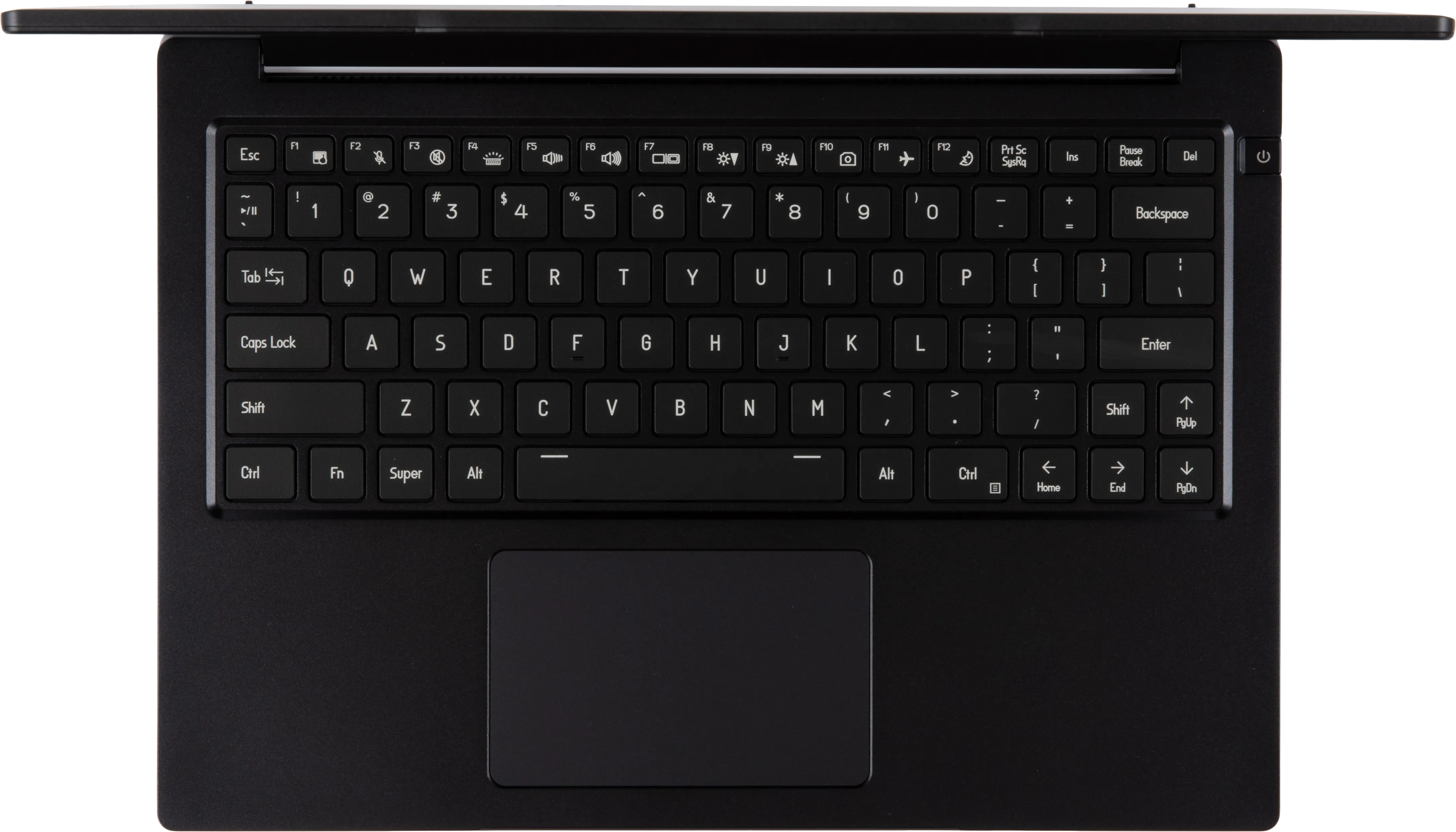
After May 2024 (lemp13-b):
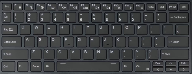
Lid:

Speakers:
The machine has two bottom-firing speakers near the front, angled outward.

Materials:
| Part | Material | Part Number |
|---|---|---|
| LCD back cover (lid) | Magnesium-aluminum alloy | 6-39-L2401-022 |
| LCD front cover (bezel) | Plastic | 6-39-L2401-012 |
| Top case (palm rests/port covers) | Magnesium-aluminum alloy | 6-39-L2402-032 |
| Bottom panel | Magnesium-aluminum alloy | 6-39-L2403-012 |
LED indicators
The color and pattern for the power/charging status LED indicate:
- Solid green: Powered on and not suspended.
- Flashing green: Powered on and suspended.
- Solid yellow: Powered off and charging.
- Off: Powered off and not charging.
Keyboard Shortcuts
The Lemur Pro has the following actions available using the Fn and Function keys:
| Key | Shortcut | Action |
|---|---|---|
 | Fn+F1 | Toggle trackpad |
 | Fn+F2 | Mute/unmute microphone |
 | Fn+F3 | Mute/unmute speakers |
 | Fn+F4 | Cycle keyboard backlight brightness |
 | Fn+F5 | Volume down |
 | Fn+F6 | Volume up |
 | Fn+F7 | Toggle displays |
 | Fn+F8 | Screen brightness down |
 | Fn+F9 | Screen brightness up |
 | Fn+F10 | Toggle webcam |
 | Fn+F11 | Toggle airplane mode |
 | Fn+F12 | Suspend |
 | Fn+` | Play/Pause |
| 1 | Fn+1 | Toggle fan between max/automatic |
Lemur Pro (Internal Overview)
Components and connectors:
Components can be replaced using the instructions under Parts & Repairs. Connectors can be reseated for troubleshooting purposes.

- RAM slot is highlighted in maroon
- M.2 SSDs are highlighted in light green
- Both slots support PCIe NVMe Gen 4
- Wireless card is highlighted in dark green
- Webcam/microphone connector is highlighted in cyan
- LCD cable connector is highlighted in yellow
- Touchpad connector is highlighted in orange
- Keyboard connector (main) is highlighted in brown
- Keyboard backlight connector is highlighted in white
- Battery connector is highlighted in light red
- CMOS battery connector is highlighted in navy
- Speaker connectors are highlighted in pink
- BIOS flash chip (U55) is highlighted in black
Lemur Pro (Parts & Repairs)
Many components in your Lemur Pro can be upgraded or replaced as necessary. Follow these step-by-step guides for instructions:
- Removing the bottom cover
- Replacing the RAM
- Replacing an M.2/NVMe SSD
- Replacing the WiFi/Bluetooth module
- Replacing the main battery
- Replacing the CMOS battery
- Replacing the fans/heatsink/thermal paste
- Replacing the speakers
Removing the bottom cover:
Removing the cover is required to access the internal components. Prior to removing the cover, ensure the AC power is unplugged and all peripherals (including SD cards and USB drives) are unplugged or removed from the system.
Part numbers:
- The bottom panel's part number is
6-39-L2403-012. - Replacement product model stickers can be obtained from System76 support.
Tools required: Cross-head (Phillips) screwdriver
Time estimate: 5 minutes
Difficulty: Easy ●
Screws: 12 total
Steps to remove the bottom cover:
- Place the machine lid-side down.
- Use a soft surface (such as a towel) to avoid scratches.
- Remove the 12 screws from the bottom panel.
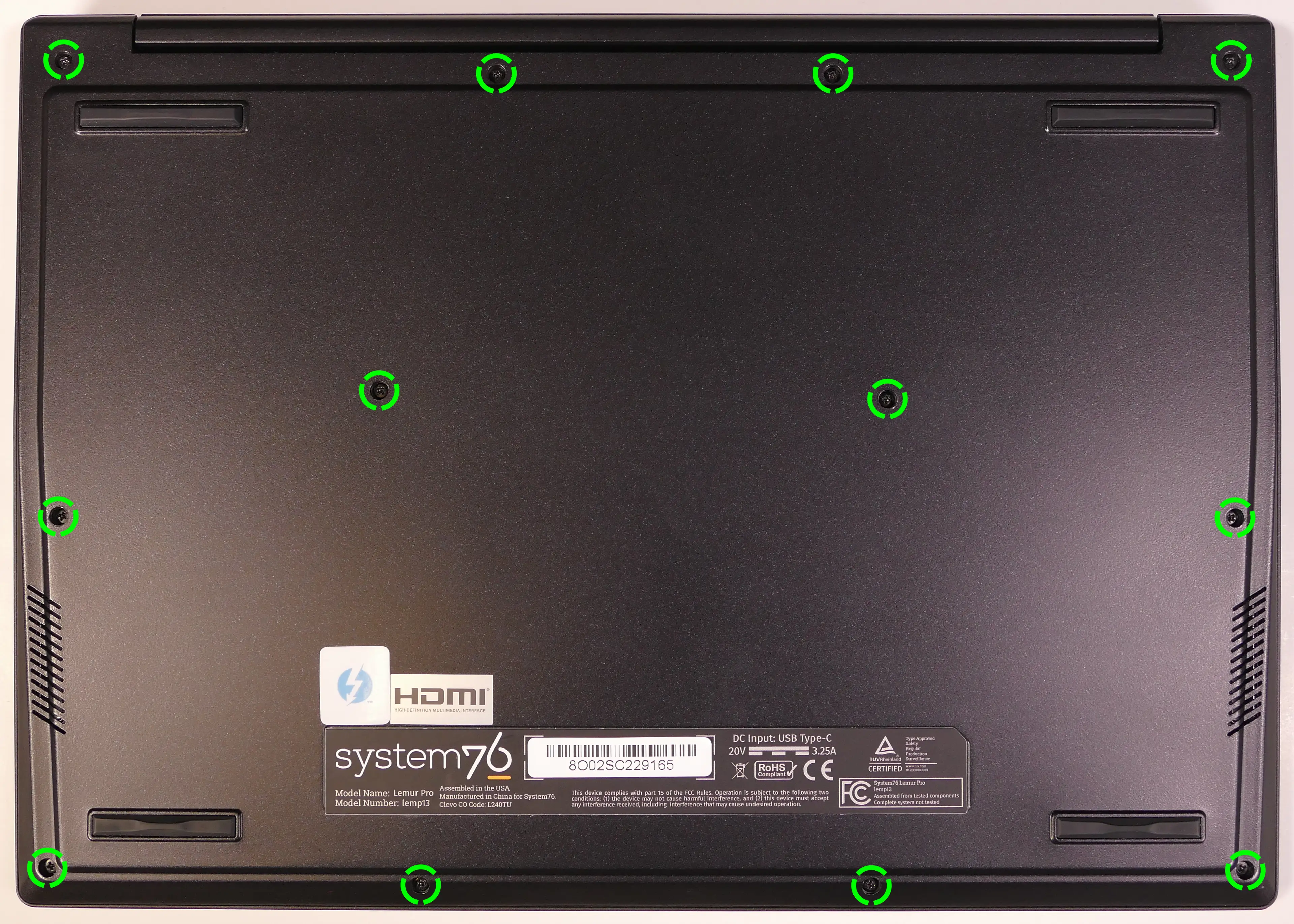
- Lift the bottom cover off, starting from the hinges in the back.
Replacing the RAM:
The Lemur Pro 13 comes with 8GB of 4800 MHz RAM soldered onto the motherboard, which cannot be replaced. There is an additional RAM slot, which can support up to a 48GB stick for 56GB of RAM total. The additional stick is a standard DDR5 SO-DIMM running at 4800 MHz.
Tools required: Cross-head (Phillips) screwdriver
Time estimate: 10 minutes
Difficulty: Easy ●
Steps to replace the RAM:
- Follow the steps above to remove the bottom cover.
- Press the small tabs on both sides of the RAM simultaneously. The RAM should spring up to an angle.
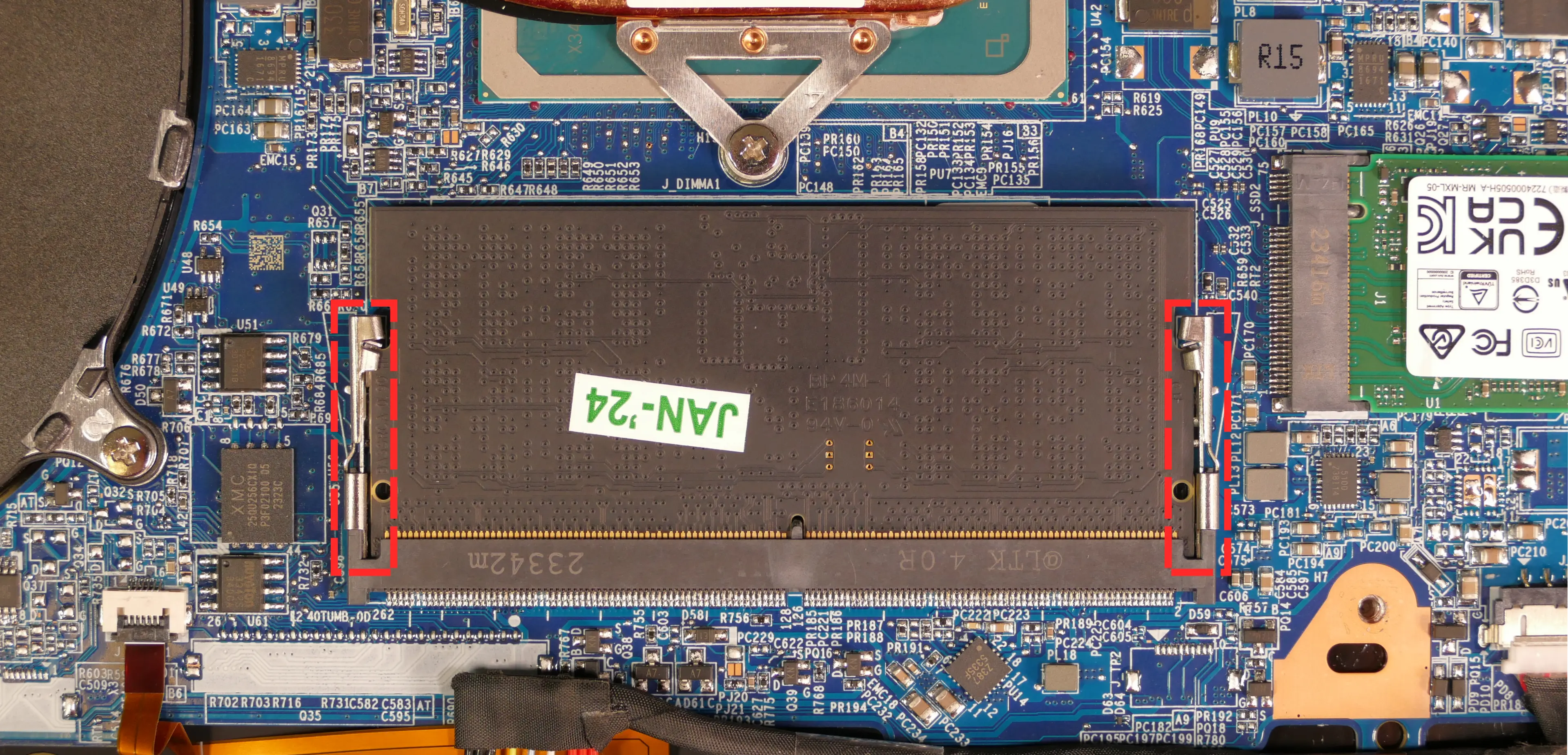
- Remove the RAM from the slot.
- Insert the new RAM (or reseat the existing RAM) by placing it into the keyed slot and pressing down until it clicks into place.
Replacing an M.2/NVMe SSD:
This model supports two M.2 SSDs. Both slots are size 2280 and support PCIe NVMe Generation 4.
Tools required: Cross-head (Phillips) screwdriver
Time estimate: 10 minutes
Difficulty: Easy ●
Steps to replace the M.2 drive:
- Follow the steps above to remove the bottom cover.
- Unscrew the retainer screw opposite the M.2 slot.
- SSD-1 is between the battery and the speaker.
- SSD-2 is next to the RAM slot.

- Remove the existing M.2 drive by pulling it out of the slot.
- Insert the new M.2 drive into the slot and hold it down.
- Replace the retainer screw.
Replacing the wireless card:
Your system's WiFi and Bluetooth are both handled by the same module. It connects with a standard M.2 2230 slot with PCIe and USB interfaces (E-key).
Part numbers:
- The standard wireless card is an Intel
AX211NGW.
Tools required: Cross-head (Phillips) screwdriver
Time estimate: 10 minutes
Difficulty: Medium ●
Steps to replace the WiFi/Bluetooth module:
- Follow the steps above to remove the bottom cover.
- Locate the wireless card (next to the CPU fan.) Remove any clear tape that is securing the wires.

- Gently remove the two antennas (highlighted red above) by pulling them up and away from the wireless card.
- Remove the retaining screw opposite the M.2 slot, highlighted yellow above.
- The wireless card will pop up at an angle. Remove the card from the M.2 slot.
- Insert the new wireless card into the M.2 slot at an angle.
- Replace the retaining screw.
- Attach the two antennas by aligning the circular fittings and pressing onto the wireless card. The connectors will snap into place. Use caution when attaching the connectors; the pins can bend, break, or snap.
Replacing the main battery:
The battery provides primary power whenever the system is unplugged.
Part numbers:
- The battery's model number is
L240BAT-4-73, and the original part number is6-87-L240S-74B01.- Third-party battery sellers may list one or both of these numbers, and may offer other compatible part numbers with the same model number.
- You can also contact System76 to purchase a replacement battery.
Tools required: Cross-head (Phillips) screwdriver
Time estimate: 10 minutes
Difficulty: Easy ●
Steps to replace the main battery:
- Follow the steps above to remove the bottom cover.
- Remove the four silver battery screws along the perimeter of the battery.

- Unplug the white connector that connects the battery to the motherboard.
- Remove the and replace the battery.
Replacing the CMOS battery:
The CMOS battery supplies power to the system's CMOS chip. UEFI settings and the computer's hardware clock are stored on the CMOS. If your system doesn't boot, you can reset the CMOS to force a low-level hardware reset. If your clock is constantly resetting, it's likely your CMOS battery needs to be replaced.
Warning (ingestion hazard): Keep batteries out of reach of children. Death or serious injury can occur if ingested. If a battery is suspected to be swallowed or inserted inside any part of the body, seek immediate medical attention. In the US, you can also call the National Battery Ingestion Hotline for guidance: 1 (800) 498-8666
Part numbers:
- The CMOS battery is a standard 3V KTS CR2032W battery.
Tools required: Cross-head (Phillips) screwdriver
Time estimate: 10 minutes
Difficulty: Medium ●
Steps to replace the CMOS battery:
- Follow the steps above to remove the bottom cover.
- Follow the steps above to remove the SSD from slot 1, if installed.
- Remove any clear tape that is securing the battery, then pull the battery away from the adhesive holding it to the case.
- If you are only clearing the CMOS and are not replacing the CMOS battery, removing the SSD and CMOS battery is optional, but will make it easier to unplug the CMOS battery connector.

- Unplug the white connector attaching the CMOS battery to the motherboard.
- To clear the CMOS, disconnect the main battery, open the lid of the machine, and hold down the power button for at least 15 seconds to discharge any residual energy in the system.
- Re-connect the CMOS battery and the main battery, and replace the SSD and bottom panel.
- Power up the machine. The system may power itself off and on after initial boot; this is normal behavior when the CMOS has been reset.
Replacing the cooling system:
If the CPU fan becomes noisy and cleaning it out doesn't fix the issue, you may need a new CPU fan. Contact support to start a warranty claim or parts purchase.
Depending on your climate and the age of the machine, it may be necessary to apply new thermal paste between the CPU and the heatsink. Thermal paste helps facilitate effective heat transfer between the CPU and the cooling equipment. These instructions can also be used in the unlikely event your heatsink needs to be replaced.
Part numbers:
- The fan/heatsink assembly's part number is
6-31-L240N-102. - The fan is an FCN
FSAP DFS5L22H15B85P EP.- The fan/heatsink is produced as a single assembly. Sourcing a replacement fan without the heatsink may not be possible.
Tools required: Cross-head (Phillips) screwdriver
Time estimate: 20 minutes
Difficulty: High ●
Steps to replace the fans/heatsink/thermal paste:
- Follow the steps above to remove the bottom cover.
- Disconnect the small connector plugging the fan into the motherboard, highlighted yellow below.
- This can alternatively be done after the fan/heatsink is removed.

- Remove the silver fan and heatsink screws in the order of the stamped numbers, starting with #1, then #2, and continuing until #5.
- Remove the heatsink/fan from the system, being careful not to bend the heatsink pipe. It may take some pressure to break the seal of the thermal paste.
- Using a paper towel, remove the existing thermal paste. You may also use a small amount of rubbing alcohol to remove excess or difficult-to-remove paste.

- After cleaning the CPU and heatsink, apply a small line of thermal paste directly onto the CPU.

- Carefully replace the fan and heatsink.
- Replace the fan and heatsink screws in the order of the stamped numbers, starting with #1, then #2, and continuing until #5.
- Plug the fan back in.
- When plugging the fan in, the black wire goes on the left (closest to the side of the machine.)
Replacing the speakers:
The system has two bottom-firing speakers, which can be removed and replaced individually.
Part numbers:
- The left speaker's model number is
L240TU-L-BASS, and its part number is6-23-5L240-0L2. - The right speaker's model number is
L240TU-R-BASS, and its part number is6-23-5L240-0R2.
Tools required: Cross-head (Phillips) screwdriver
Time estimate: 10 minutes
Difficulty: Medium ●
Steps to replace the speakers:
- Follow the steps above to remove the bottom cover.
- Disconnect the speaker wire from the motherboard.
- This can alternatively be done after freeing the speaker.

- Pull the tops of the black rubber circles over the gray tabs holding them in place.
- Lift the speaker up and off of the mounting posts.
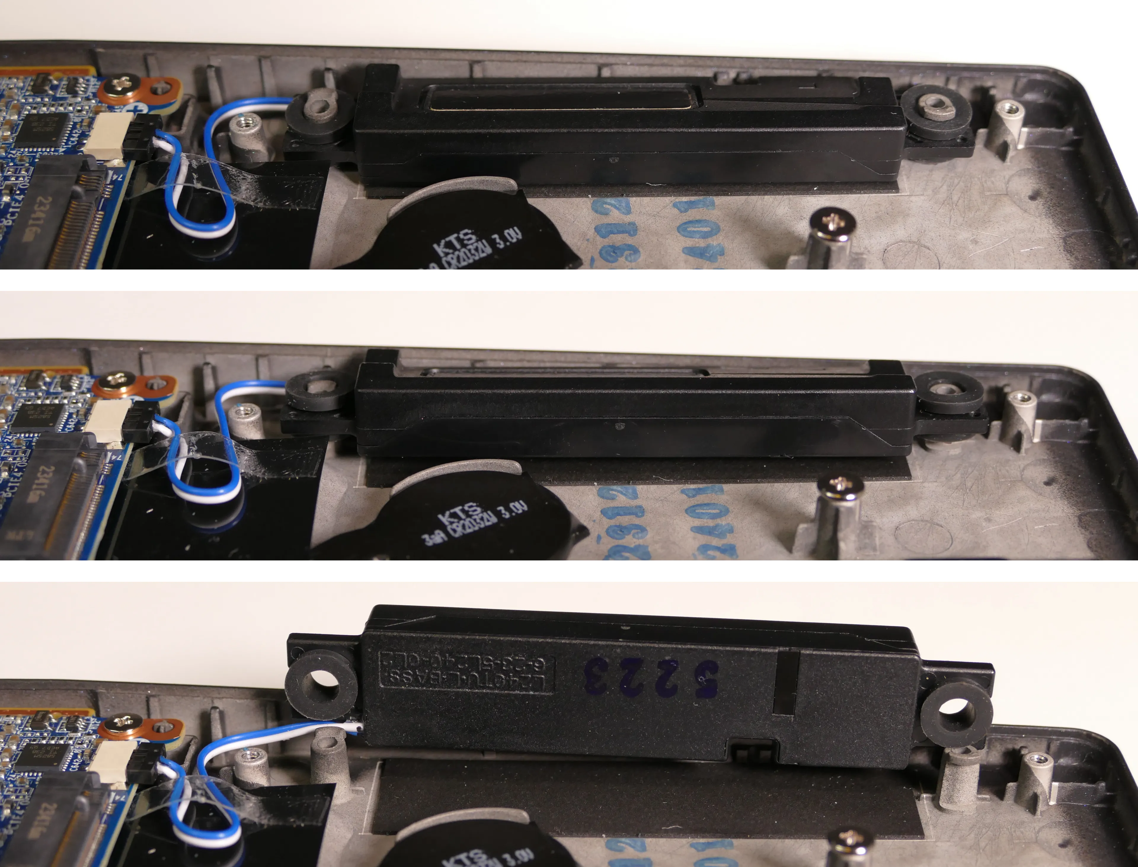
- Slide the new speaker onto the mounting posts and connect it to the motherboard.
Meerkat (meer10)
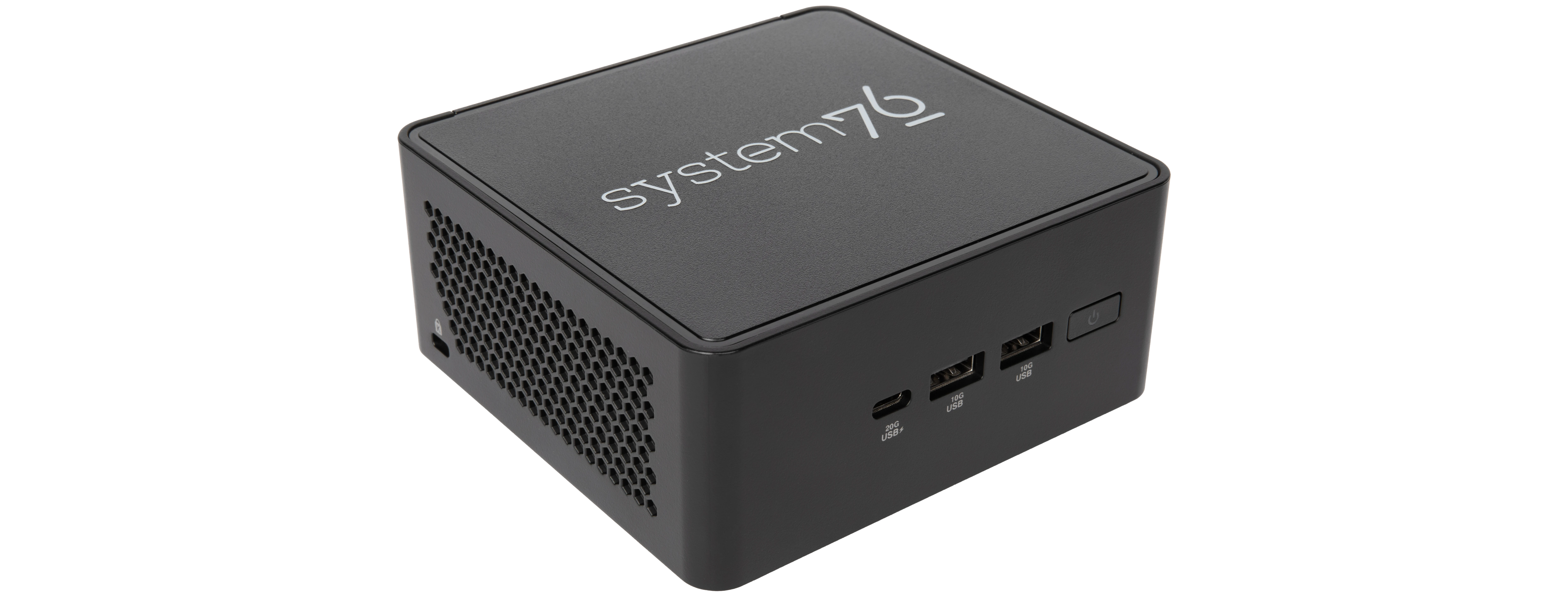
The System76 Meerkat is a desktop with the following specifications:
- CPU
- Supports Intel Core Ultra Series 2 (Arrow Lake), Core Series 2 (Raptor Lake), and Core Series 1 (Raptor Lake) CPUs
- Graphics
- GPU: Dependent on CPU
- Core Ultra 7 255H: Intel Arc 140T GPU
- Requires 2 SO-DIMMs for Arc graphics
- Core 7 240H: Intel Graphics (integrated)
- Core Ultra 5 225H: Intel Arc 130T GPU
- Requires 2 SO-DIMMs for Arc graphics
- Core 3 100U: Intel Graphics (integrated)
- Core Ultra 7 255H: Intel Arc 140T GPU
- Video output:
- 2x HDMI 2.1
- 2x DisplayPort 2.1 over USB-C
- GPU: Dependent on CPU
- Memory
- Up to 96GB (2x48GB) Dual Channel DDR5 SO-DIMMs @ 5600 MHz
- Networking
- 1x 2.5-Gigabit Ethernet (built-in)
- 1x 2.5-Gigabit Ethernet (optional add-on)
- WiFi 7 and Bluetooth 5.4 (card dependent on model):
- Core Ultra 7 and Core Ultra 5 models: Intel BE201
- Core 7 and Core 3 models: Intel BE202
- Power
- Core Ultra 7, Core 7, and Core Ultra 5 models:
- 120W (19V, 6.32A) DC-in port
- Barrel size: 5.5mm (outer), 2.5mm (inner)
- 120W (19V, 6.32A) DC-in port
- Core 3 model:
- 90W (19V, 4.74A) DC-in port
- Barrel size: 5.5mm (outer), 2.5mm (inner)
- 90W (19V, 4.74A) DC-in port
- Core Ultra 7, Core 7, and Core Ultra 5 models:
- Sound
- 7.1-channel digital audio output over HDMI and USB-C
- Storage
- Core Ultra 7 and Core Ultra 5 models:
- 1x M.2 (2280) PCIe NVMe Gen 5
- 1x M.2 (2242) PCIe NVMe Gen 4
- Expansion module adapts to 2280
- Core 7 and Core 3 models:
- 1x M.2 (2280) PCIe NVMe Gen 4
- 1x M.2 (2242) PCIe NVMe Gen 4
- Expansion module adapts to 2280
- Core Ultra 7 and Core Ultra 5 models:
- USB
- 2x USB4 Type-C with Thunderbolt 4
- Both ports support DisplayPort over USB-C
- 1x USB 3.2 Gen 2 Type-A
- 1x USB 2.0 Type-A
- 2x USB4 Type-C with Thunderbolt 4
- Dimensions
- 11.7cm x 11.2cm x 5.4cm
Meerkat (External Overview)
Front side:

Left side:

Right side:

Back side:
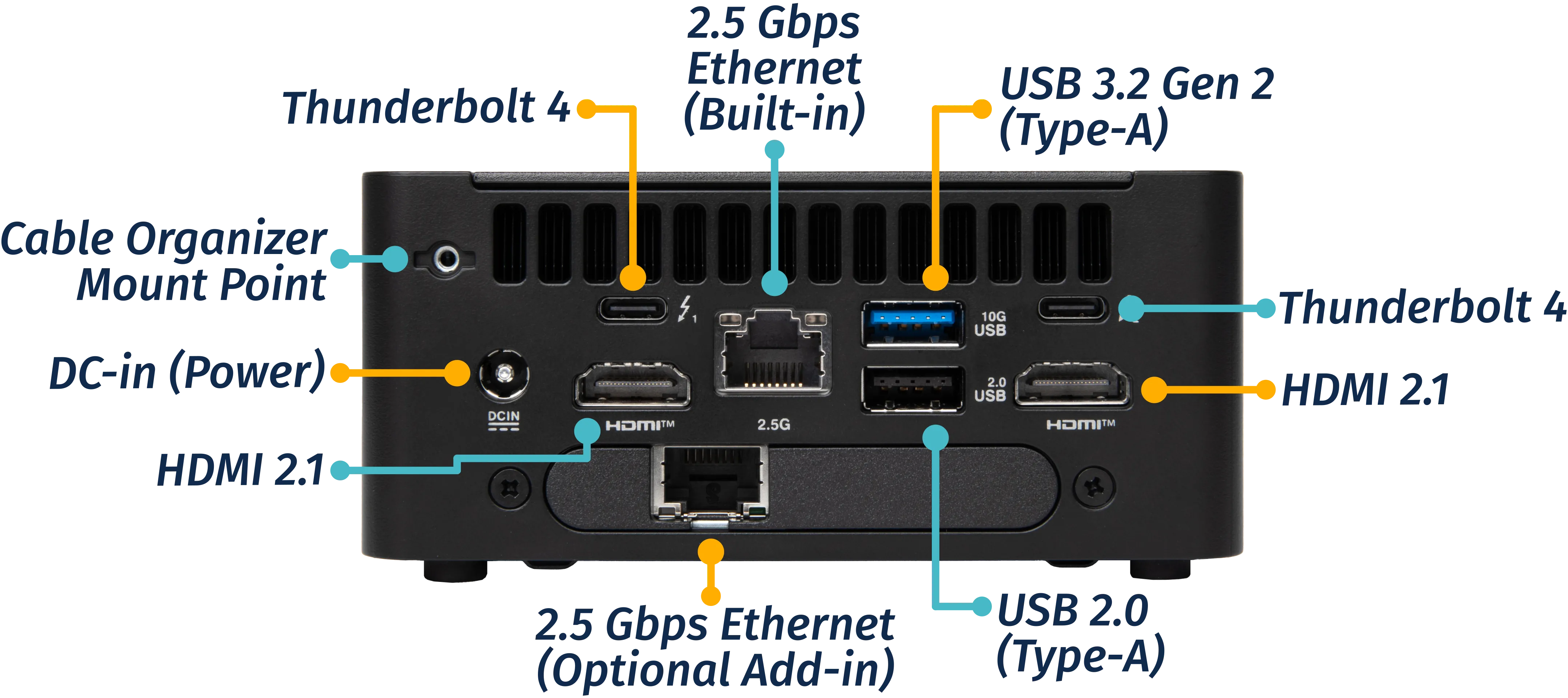
Top:

Meerkat (Internal Overview)
Component overview:
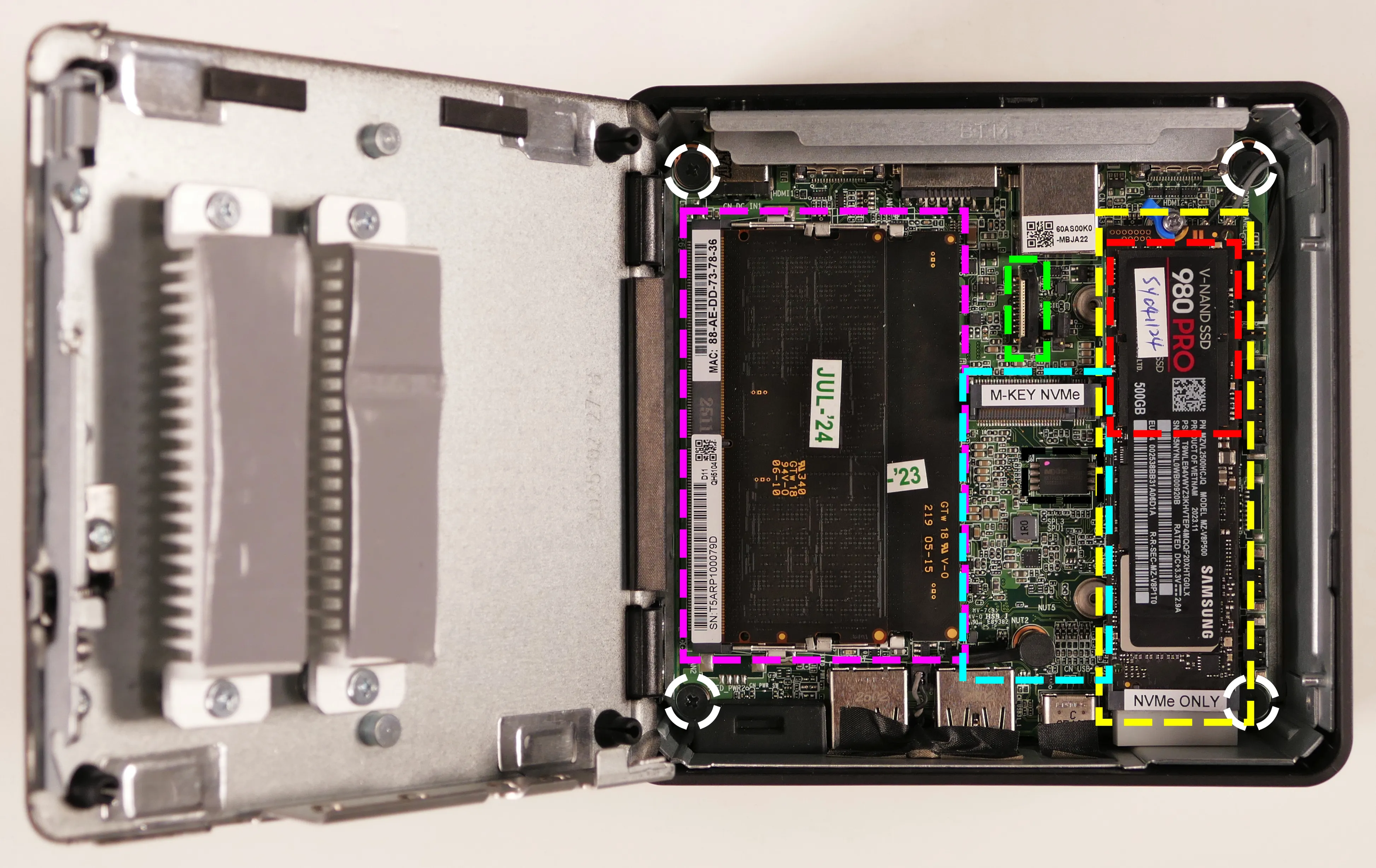
- M.2 2280 SSD slot is highlighted in yellow
- Supports PCIe NVMe Gen 5 with the Core Ultra 7 or Core Ultra 5 CPUs
- Supports PCIe NVMe Gen 4 with the Core 7 or Core 3 CPUs
- Wireless card (underneath the primary M.2 SSD) is highlighted in red
- M.2 2242 (PCIe NVMe Gen 4) SSD slot is highlighted in cyan
- Optional M.2 2280 adapter (included with additional storage purchase) plugs into this slot
- Header for optional second Ethernet port expansion slot is highlighted in green
- RAM slots are highlighted in pink
- Motherboard screws are highlighted in white
- BIOS chip is highlighted in black
Meerkat (Parts & Repairs)
Several components in your Meerkat can be upgraded or replaced as necessary. Power the machine off and unplug all peripherals before working with any internal components. Then, follow these step-by-step guides for instructions:
- Opening the bottom panel
- Replacing an expansion card
- Replacing an M.2 drive
- Replacing the RAM
- Replacing the WiFi/Bluetooth module
- Removing the top cover
- Removing the motherboard
- Replacing the fan
- Replacing the CMOS battery
- Replacing the thermal paste
- Installing the cable keeper
- Mounting with the VESA adapter
Opening the bottom panel:
The bottom panel can be opened to access the internal components.
Tools required: Cross-head (Phillips) screwdriver
Time estimate: 1 minute
Difficulty: Easy ●
Steps to open the bottom panel:
- Place the machine lid-side down.
- Use a soft surface (such as a towel) to avoid scratches.
- Remove the screw holding the latch shut.
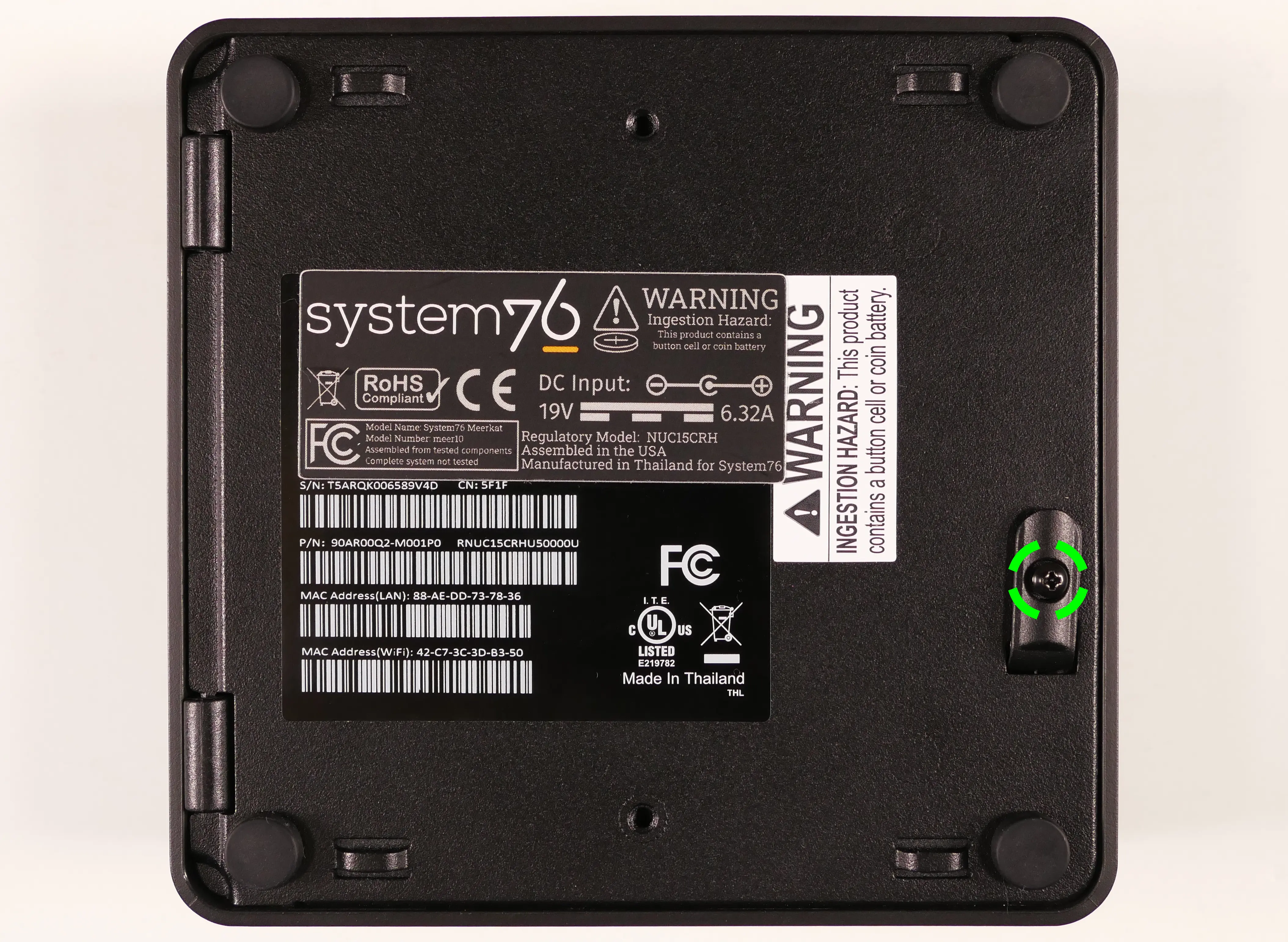
- Pull the rectangular latch open.
- Pull the bottom panel open once unlatched.
- The side opposite the latch is hinged, and will not come away from the chassis.
Replacing an expansion card:
The Meerkat 10 supports an optional expansion card to add either a second 2280-size M.2 SSD slot (which connects via the built-in 2242-size slot) or a second 2.5-gigabit Ethernet port. This card can be replaced or swapped for another type.
Tools required: Cross-head (Phillips) screwdriver
Time estimate: 10 minutes
Difficulty: Easy ●
Steps to replace the storage expansion card:
- Follow the steps above to open the bottom panel.
- If an M.2 drive is installed in the 2280 adapter slot, slide the yellow clip away from the drive to free the drive, then remove the drive from the slot.
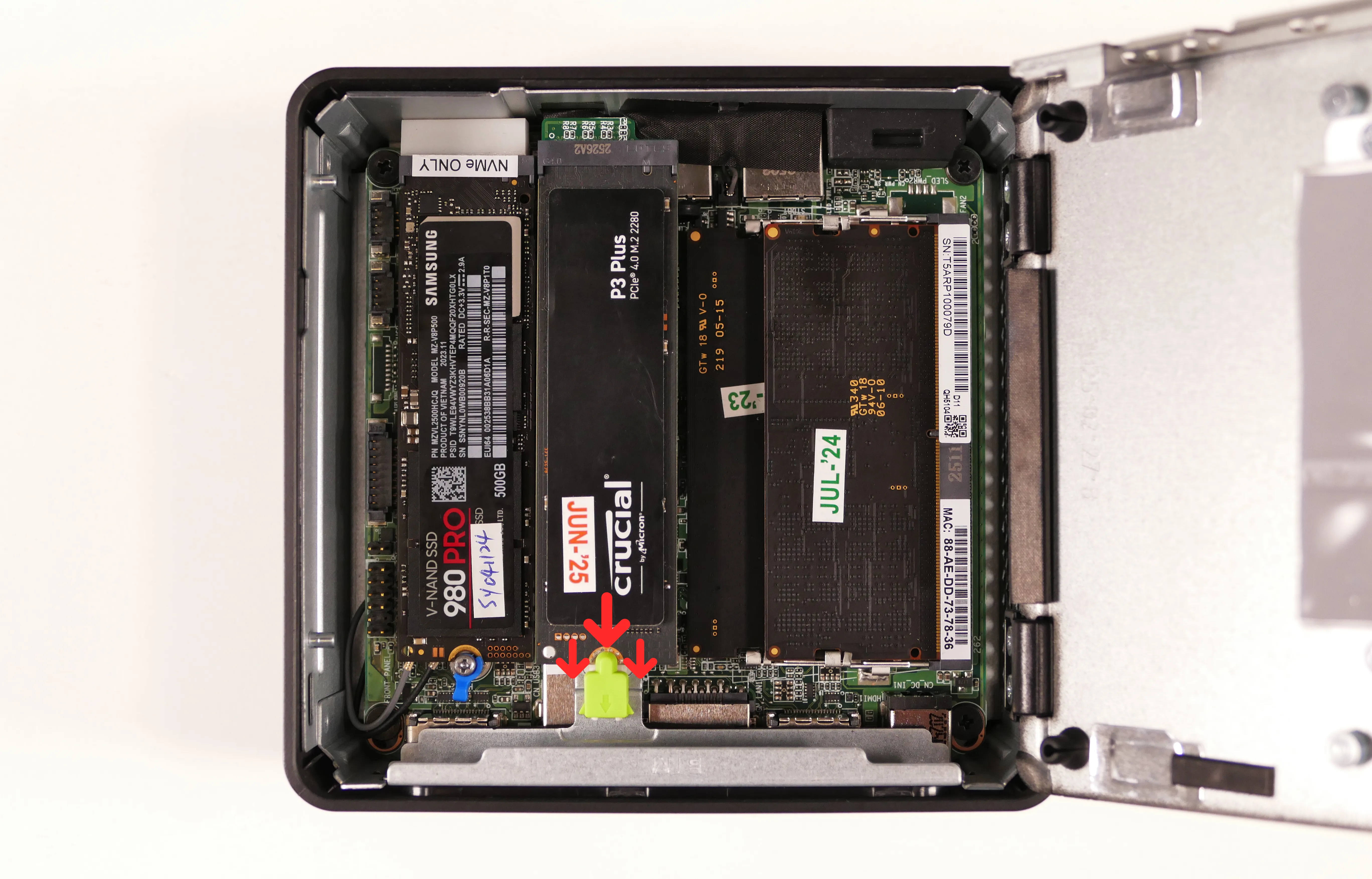
- To remove the 2280 adapter from the motherboard, pull the black pin out of its mounting hole, then remove the adapter from the
M-KEY NVMeslot.
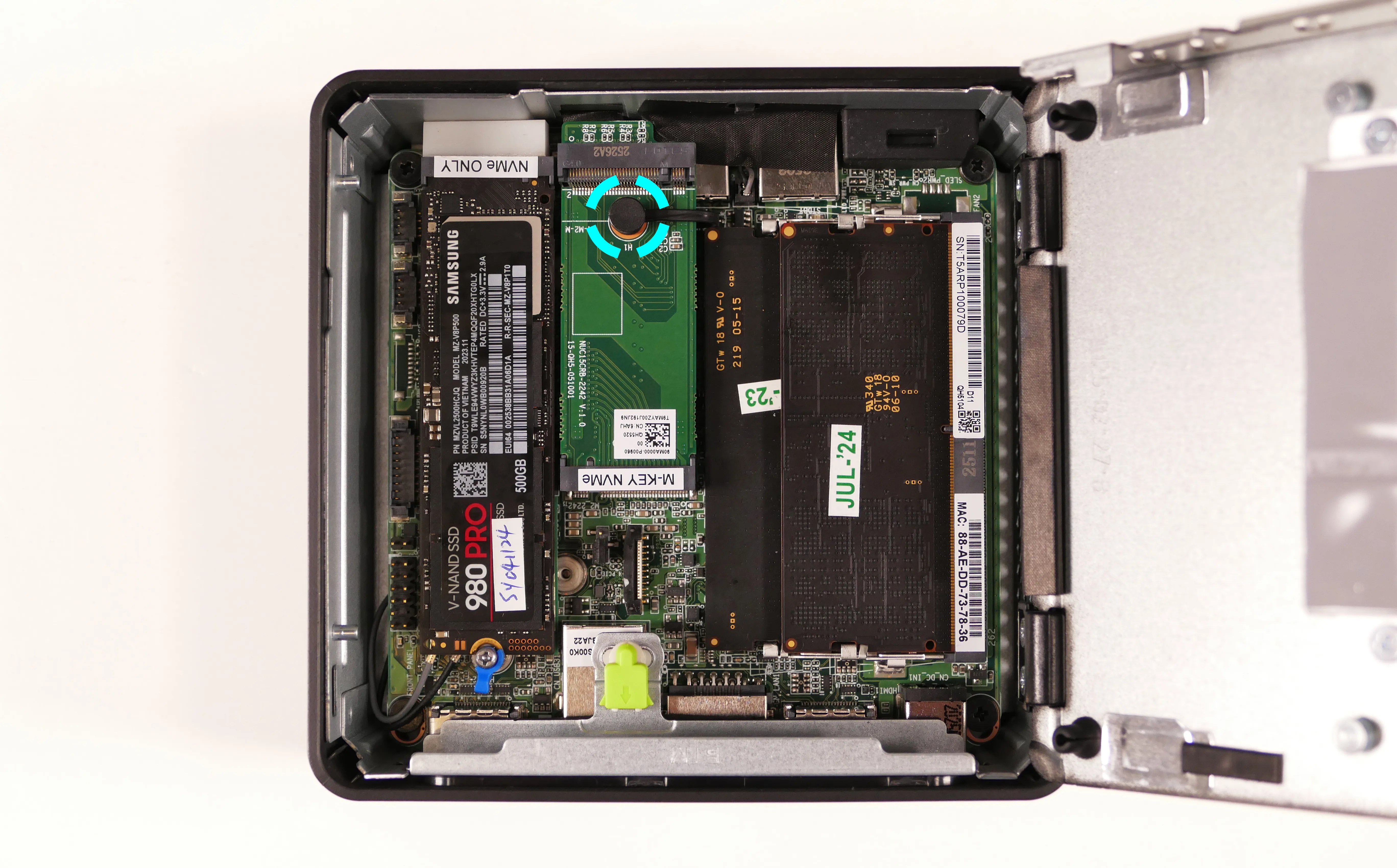
- To remove the storage slot cover from the chassis, remove the two back screws holding it in place.
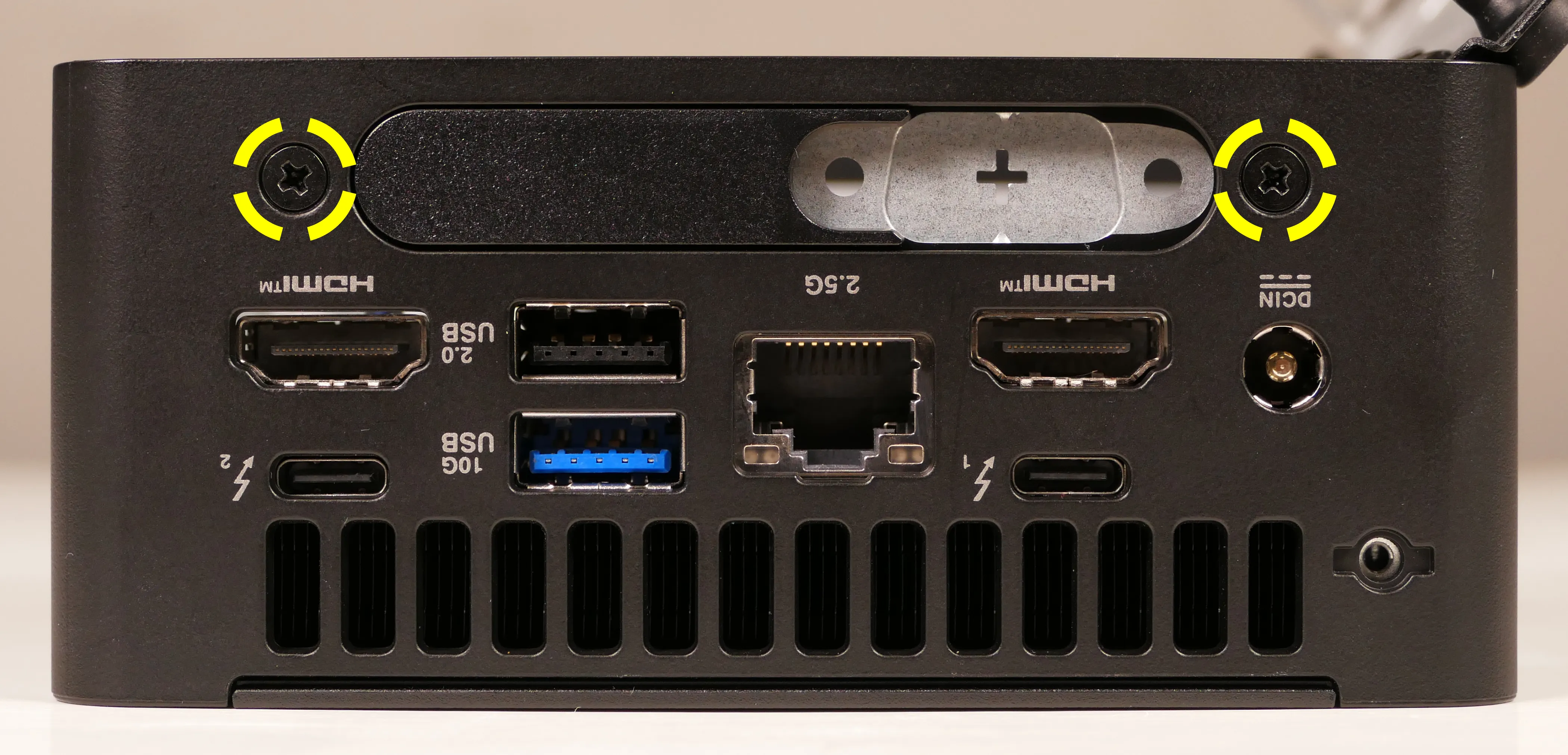
Steps to replace the Ethernet expansion card:
- Follow the steps above to open the bottom panel.
- Remove the two back screws holding the expansion card in place.
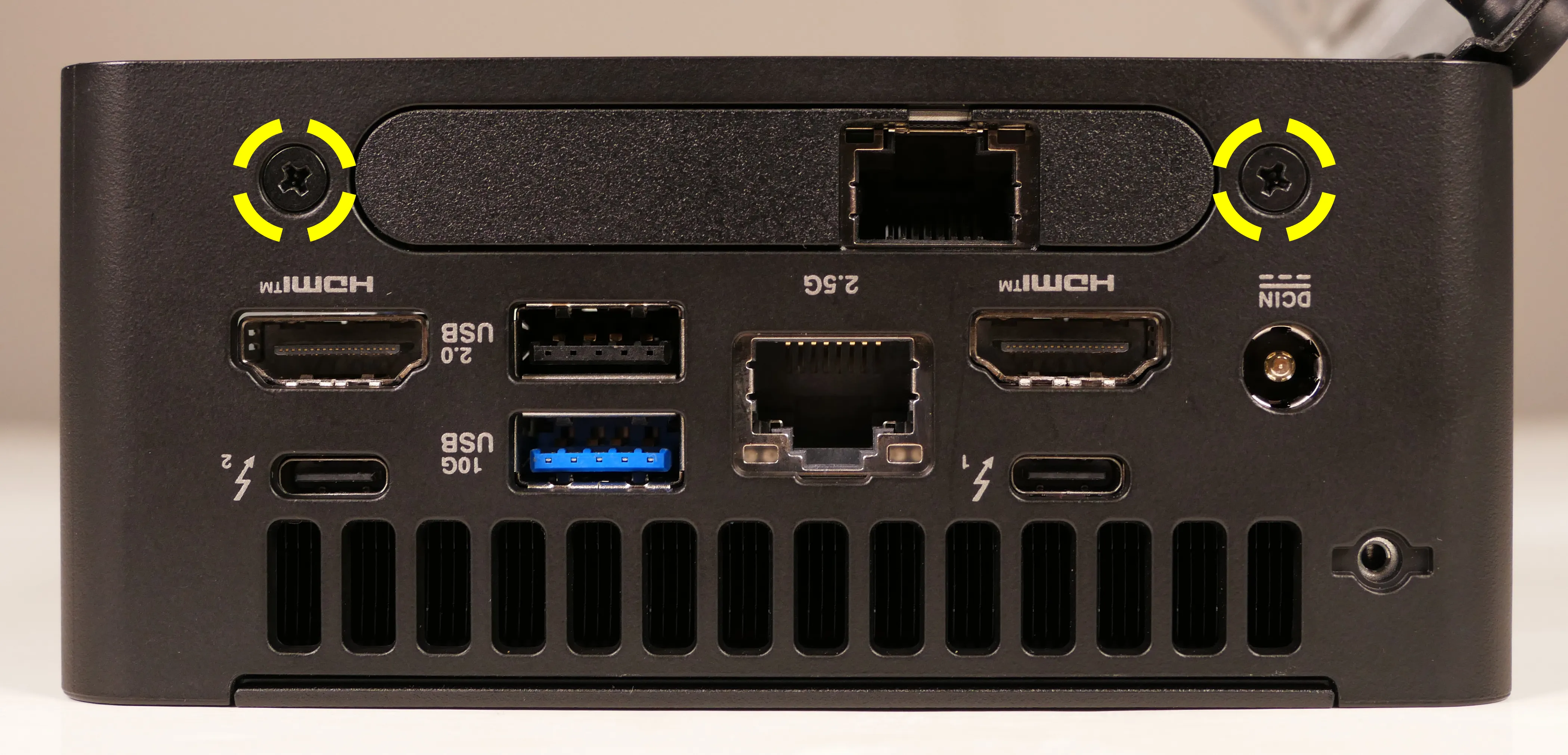
- Pull the black clip surrounding the connector away from the motherboard to unlock the connector, then unplug the connector from the motherboard.
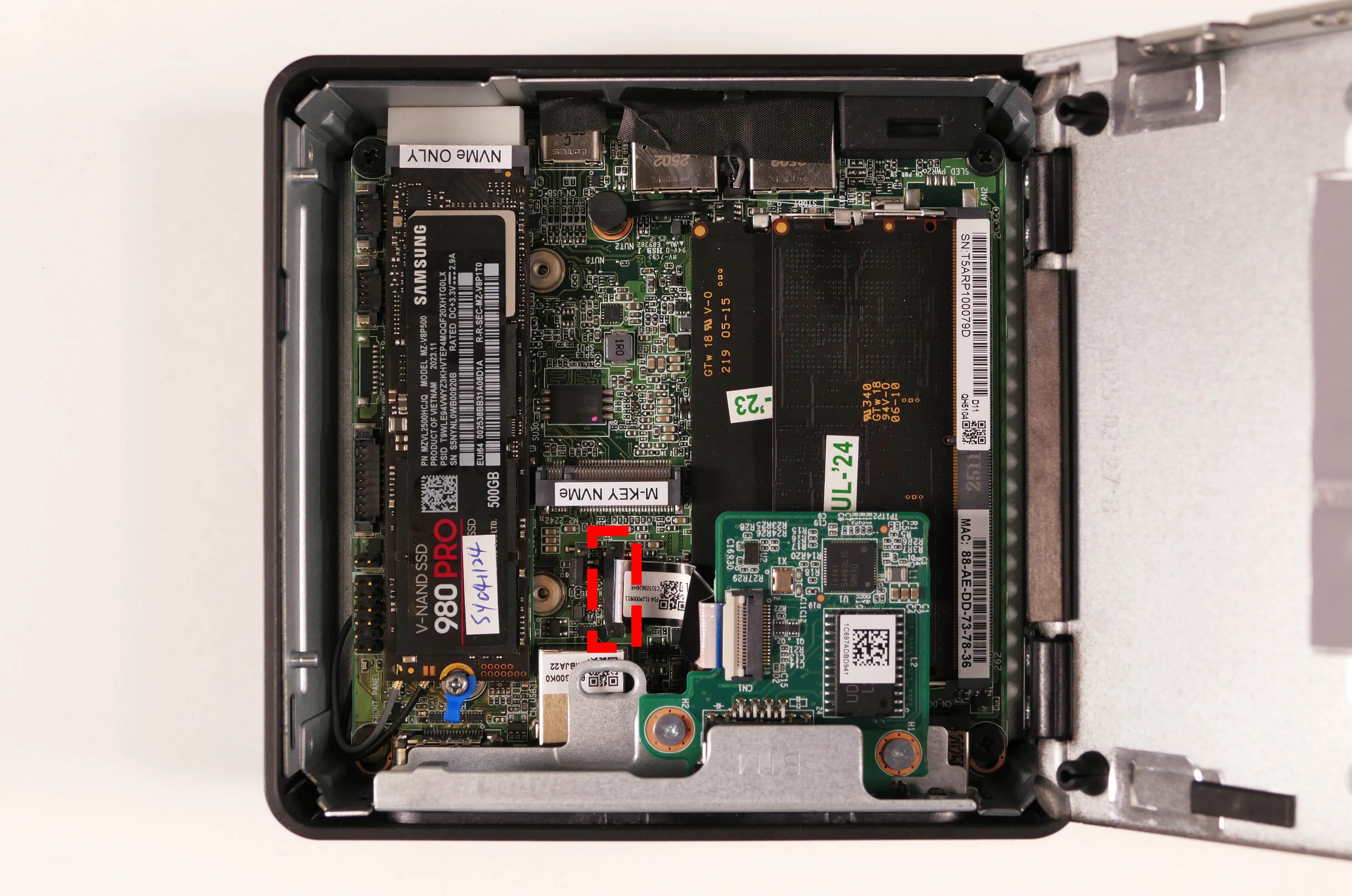
Steps to replace the blank expansion slot cover:
- Follow the steps above to open the bottom panel.
- Remove the two back screws holding the expansion slot cover in place.
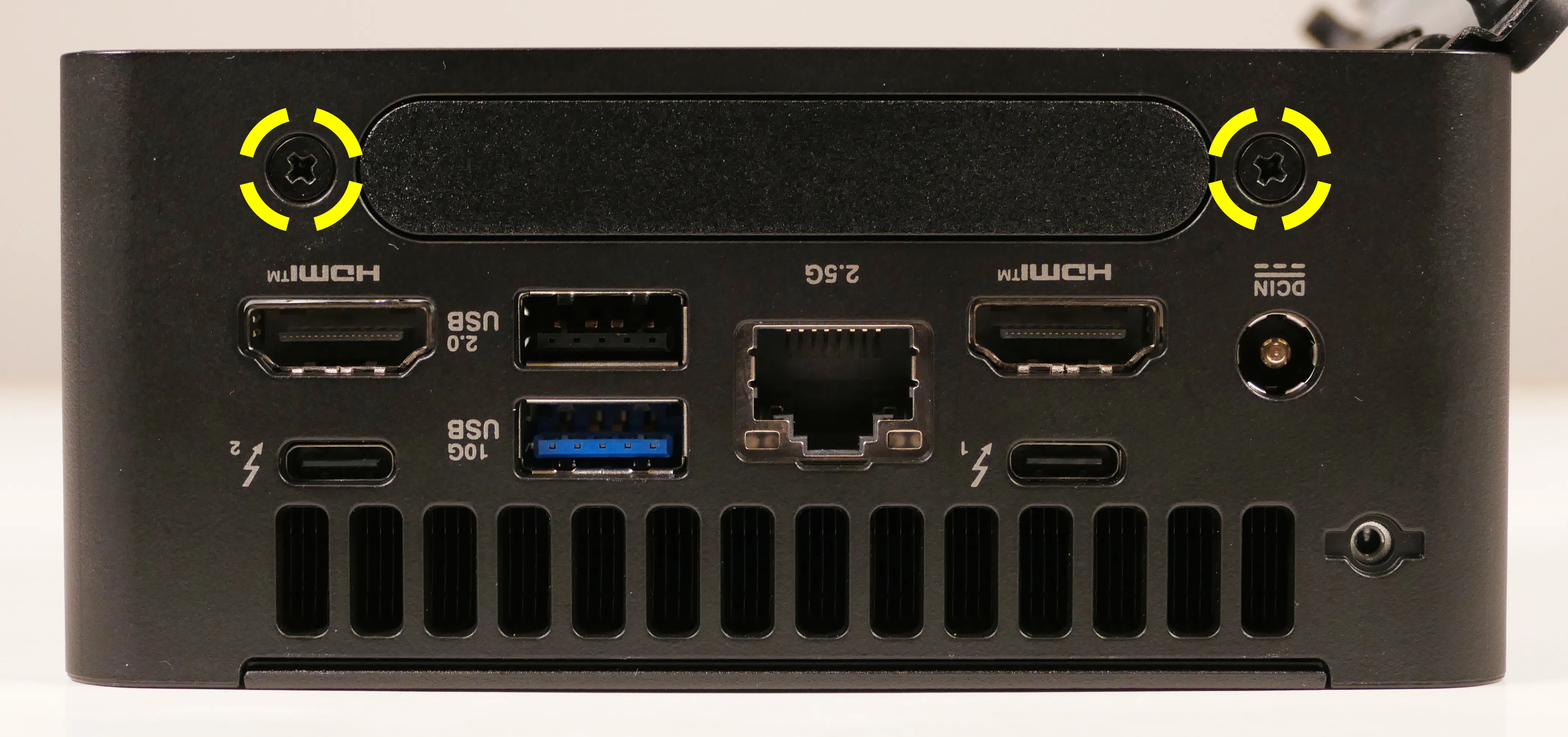
- When reinstalling the slot cover, the side labeled
BTMfaces the bottom cover of the chassis, and the side with padding faces the I/O ports within the chassis.
Replacing an M.2 drive:
Your Meerkat has two M.2 slots.
- The first slot fits size 2280 drives.
- On Core Ultra 7 and Core Ultra 5 models, the first slot supports PCIe NVMe Gen 5.
- On the Core 7 and Core 3 models, the first slot supports PCIe NVMe Gen 4.
- The second slot supports PCIe NVMe Gen 4 drives, and fits drives of size 2242 by default. An optional adapter can be installed to fit 2280 drives in the 2242-size slot. The 2280 adapter is installed by default if you purchased additional storage as part of your original order.
Tools required: Cross-head (Phillips) screwdriver
Time estimate: 5 minutes
Difficulty: Easy ●
Steps to replace the M.2 drives:
- Follow the steps above to open the bottom panel.
- Free the drive from its retainer clip.
- For the primary slot (Gen 5 or Gen 4, depending on CPU model), nearest the side of the chassis, twist the blue clip clockwise to free the drive.
- For the secondary (Gen 4) adapter slot, nearest the RAM, slide the yellow clip away from the drive.
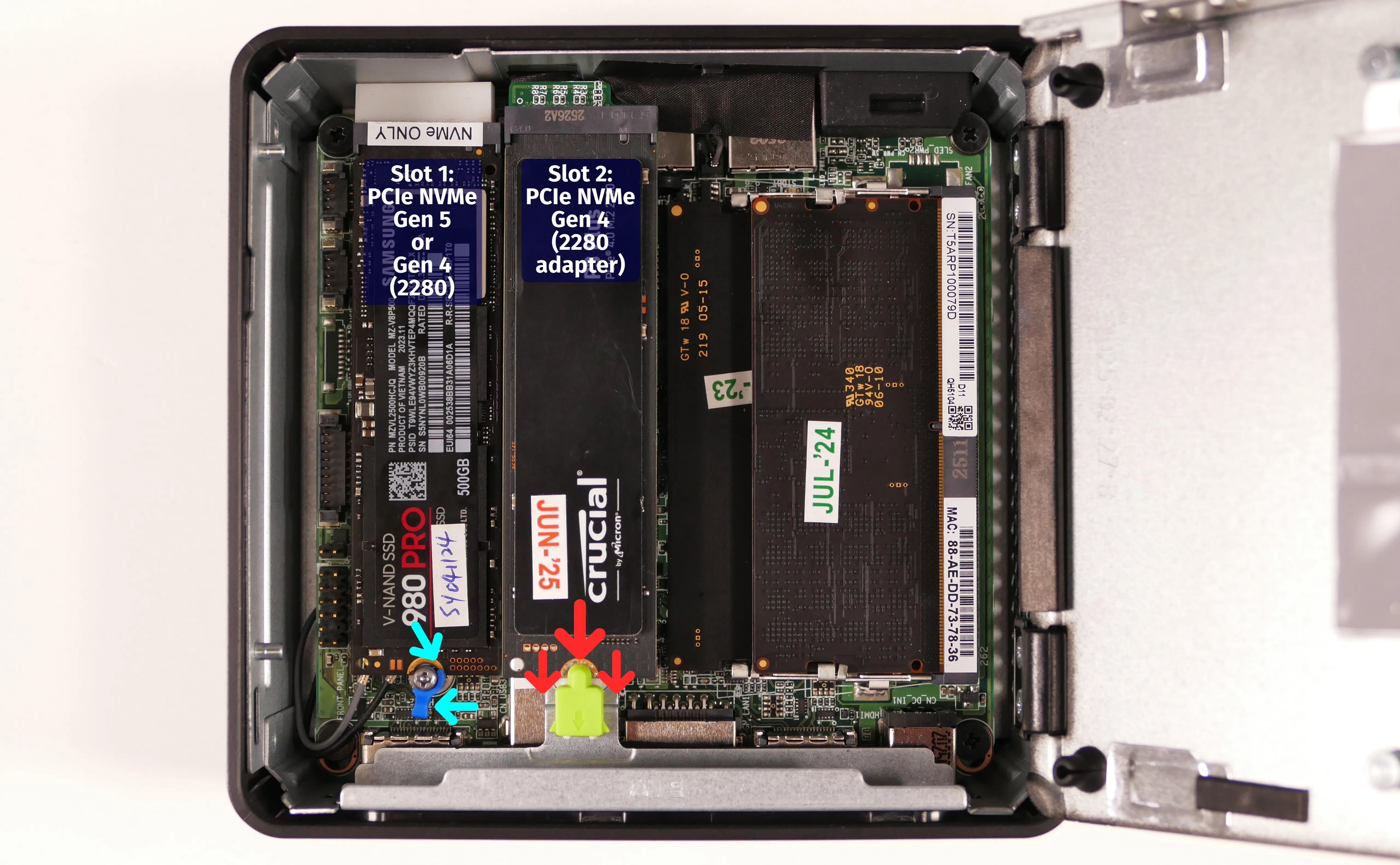
- If an aftermarket 2242-size drive has been installed directly into the secondary (Gen 4) slot, as shown below, pull the black plastic pin out of the mounting hole.
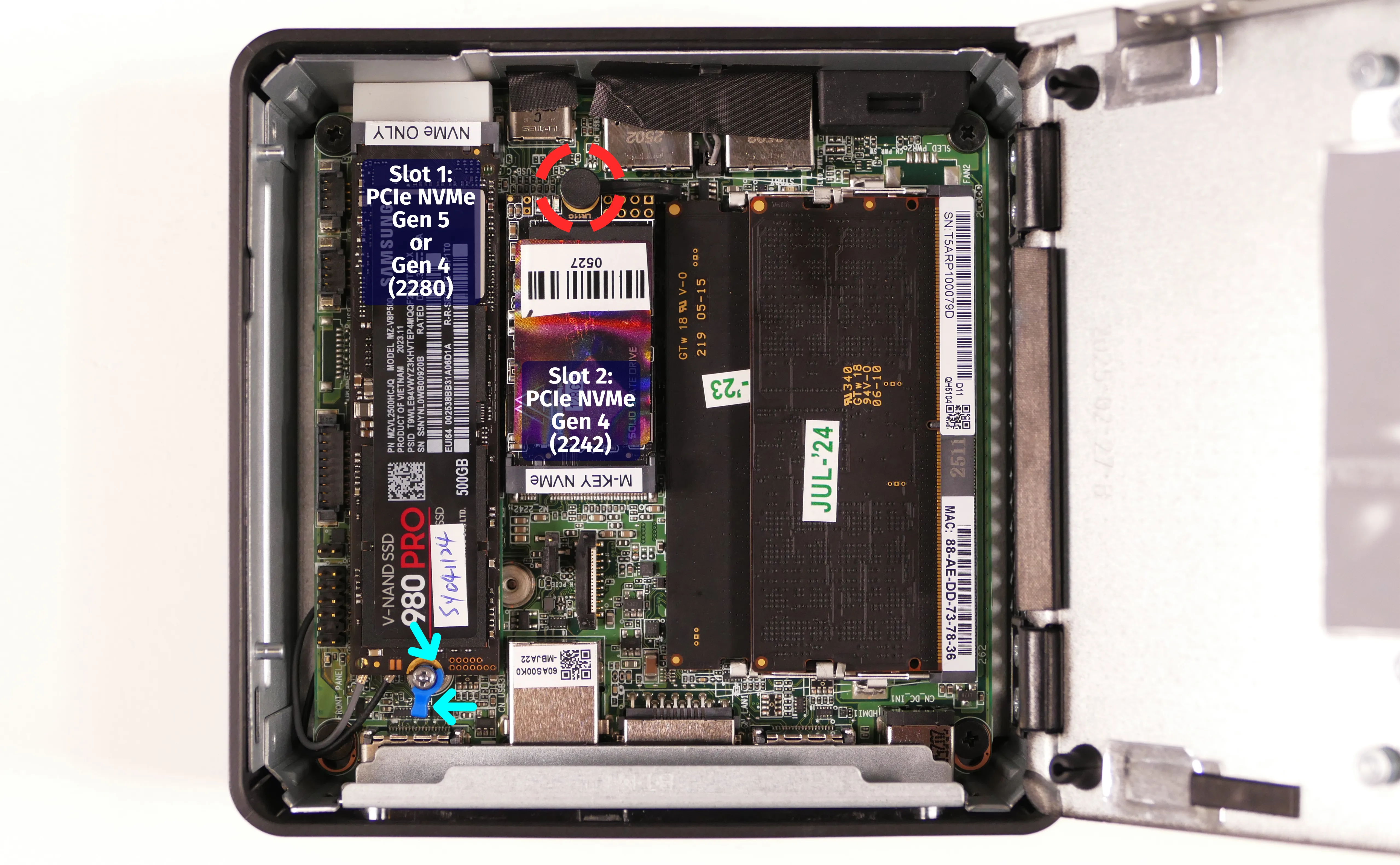
- Remove the old drive from the slot and insert the new drive into the slot.
- Secure the new drive in place as necessary.
- If you installed a drive into the primary (Gen 5 or Gen 4) slot, twist the blue clip counterclockwise to lock the drive into place.
- If you installed a drive into the secondary (Gen 4) adapter, the yellow clip locks automatically.
- If you installed a 2242-size drive into the secondary (Gen 4) slot, press the black pin back into the hole to hold the drive down.
Replacing the RAM:
The Meerkat 10 supports up to 96GB (2x48GB) of DDR5 SO-DIMMs running at 5600MHz. If you've purchased new RAM, need to replace your RAM, or are reseating your RAM, follow these steps.
Tools required: Cross-head (Phillips) screwdriver
Time estimate: 5 minutes
Difficulty: Easy ●
Steps to replace the RAM:
- Follow the steps above to open the bottom panel.
- Pull the small tabs on both sides of the RAM away from the RAM stick simultaneously. The RAM should spring up to an angle.

- Remove the RAM from the slot.
- Insert the new RAM (or reseat the existing RAM) by placing it in the keyed slot and pressing down until it clicks into place.
Replacing the wireless card:
Your Meerkat's WiFi and Bluetooth are both handled by the same module. It is a standard M.2 2230 slot with PCIe and USB interfaces (E-key).
Part numbers:
- Preinstalled wireless card (dependent on model):
- Core Ultra 7 and Core Ultra 5 models: Intel
BE201 - Core 7 and Core 3 models: Intel
BE202
- Core Ultra 7 and Core Ultra 5 models: Intel
Tools required: Cross-head (Phillips) screwdriver, 5.0 mm hex socket
Time estimate: 15 minutes
Difficulty: Medium ●
Steps to replace the WiFi/Bluetooth module:
- Follow the steps above to open the bottom panel and remove the M.2 drive from Slot 1.
- Gently remove the two antennas (highlighted yellow below) by pulling them up and away from the wireless card.

- Remove the wireless card screw holding the wireless card down.
- The wireless card screw also includes the blue plastic clip for the primary M.2 drive, a small spring, and the nut underneath the screw.
- If the plastic clip and spring come away from the nut underneath them, then you'll also need to remove the nut to free the wireless card.
- The wireless card will pop up at an angle. Remove the card from the M.2 slot.
- Insert the new wireless card into the M.2 slot at an angle.
- Replace the retaining screw (including the nut underneath and the plastic clip and spring, if the pieces separated while removing them).
- Attach the two antennas by aligning the circular fittings and pressing onto the wireless card. The connectors will snap into place.
- Use caution when attaching the connectors; the pins can bend, break, or snap.
Removing the top cover:
The black plastic top cover of the Meerkat (which includes a System76 logo sticker by default) can be removed from the rest of the chassis.
Tools required: None
Time estimate: 1 minute
Difficulty: Easy ●
Steps to remove the top cover:
- Pull the top cover off of the chassis, starting at the gap in the back.
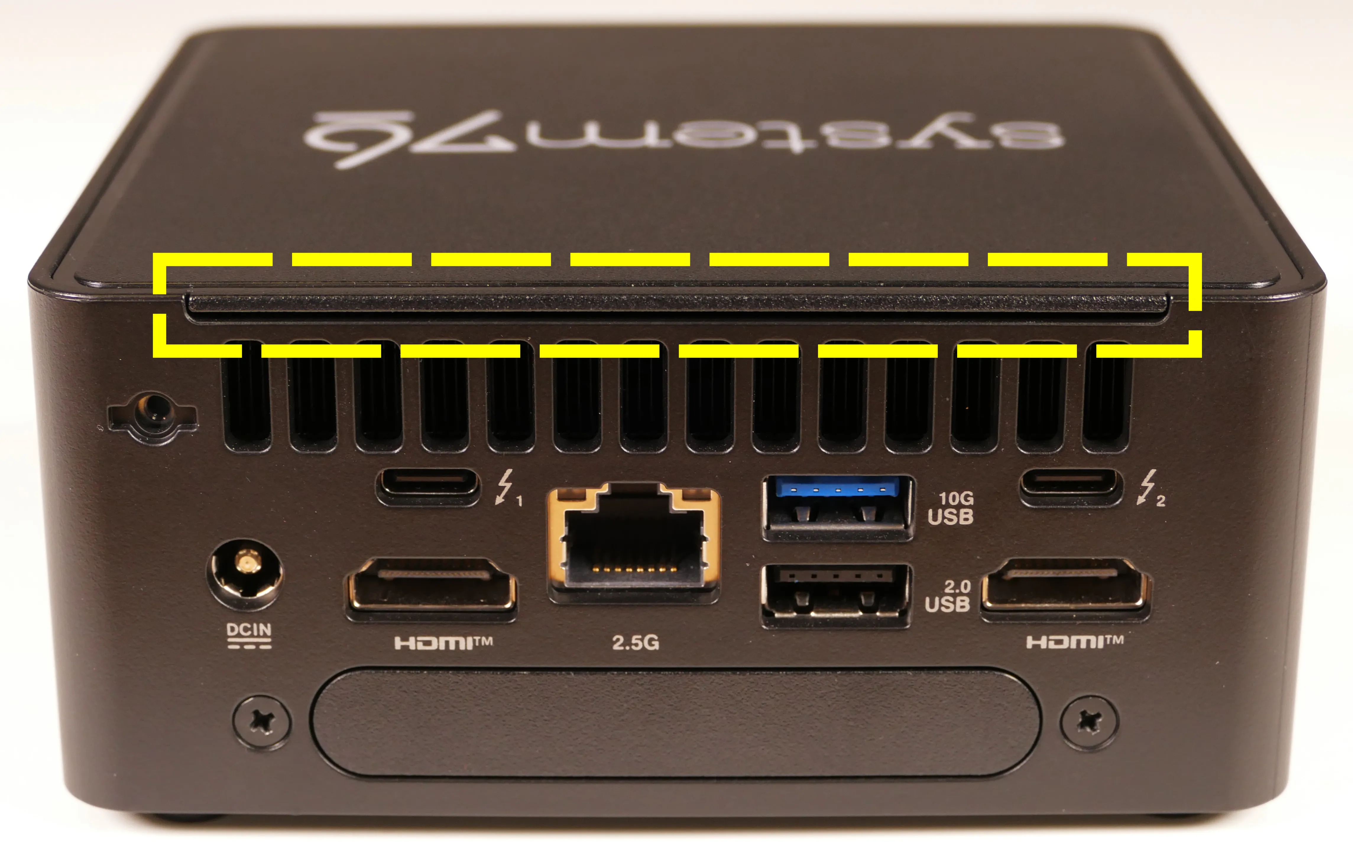
Removing the motherboard:
Removing the motherboard is necessary for replacing the CMOS battery, cooling fan, and thermal paste.
Tools required: Cross-head (Phillips) screwdriver
Time estimate: 20 minutes
Difficulty: High ●
Steps to remove the motherboard:
- Follow the steps above to remove the top cover.
- Unscrew the four silver corner screws and unhook the corners of the grey wireless antenna wire from the black plastic portions of the chassis.
- Do not attempt to pull on or remove either end of the wireless antenna wire at this time; instead, just unhook the middle portion from its channels in the corners of the chassis.
- Follow the steps above to open the bottom panel, remove the back expansion slot (or placeholder), and remove the M.2 drive from Slot 1.
- While holding the Meerkat, push on the flat silver portion of the chassis (shown above) to move the internal motherboard cage out of the black plastic outer chassis shell.
- The bottom cover is attached to the silver inner cage, and will also come out of the outer shell.
- Unplug the two wireless antenna wires from the wireless card, and unscrew the four black corner screws holding the motherboard into the silver cage.
- Carefully remove the motherboard from the silver cage.
- Because the back ports extend slightly through the cutouts in the silver cage, it's easiest to lift from the front side first, pivoting the board against the back side of the chassis.
- The front ports have tape securing the motherboard to the front of the chassis, so it takes some force to peel the tape off while raising the motherboard. The motherboard can be pushed by the edge of the fan below while lifting from the top.
- When reinstalling the motherboard, ensure both the front and back ports are aligned with their chassis cutouts and no tape is obstructing the ports. The port alignment may not be perfect until all screws have been replaced.
Replacing the fan:
The cooling fan can be removed to clean dust out of the cooling system, or to access components underneath it, like the CPU heatsink or the CMOS battery. The fan can also be replaced if it's failed or become excessively noisy.
Part numbers:
- The fan is an AVC
BAZC0810R5HY013.
Tools required: Cross-head (Phillips) screwdriver
Time estimate: 25 minutes
Difficulty: High ●
Steps to replace the fan:
- Follow the steps above to remove the top cover, open the bottom panel, remove the back expansion slot (or placeholder), remove the M.2 drive from Slot 1, unplug the wireless card, and remove the motherboard.
- Unscrew the two fan screws.
- Unplug the fan connector.
- Pull the fan away from the heatsink.
- The black tape holding the fan onto the heatsink can be peeled away with the fan.
- If the white plastic washers come out of the fan's screw holes while removing the fan, place them back into the fan's screw holes (or onto the motherboard's screw hole posts) before reinstalling the fan.
Replacing the CMOS battery:
The CMOS battery supplies power to the system's CMOS chip, where UEFI settings and the computer's hardware clock are stored. If your clock is constantly resetting, your CMOS battery may need to be replaced.
You can also temporarily disconnect the CMOS battery to reset the system's CMOS. Due to the position of the CMOS connector, it's easiest to remove the CMOS battery in order to do this.
Warning (ingestion hazard): Keep batteries out of reach of children. Death or serious injury can occur if ingested. If a battery is suspected to be swallowed or inserted inside any part of the body, seek immediate medical attention. In the US, you can also call the National Battery Ingestion Hotline for guidance: +1 (800) 498-8666
Part numbers:
- The CMOS battery is a standard 3V KTS CR2032 battery.
Tools required: Cross-head (Phillips) screwdriver
Time estimate: 28 minutes
Difficulty: High ●
Steps to replace the CMOS battery:
- Follow the steps above to remove the top cover, open the bottom panel, remove the back expansion slot (or placeholder), remove the M.2 drive from Slot 1, unplug the wireless card, remove the motherboard, and remove the fan.
- Slowly pull the CMOS battery away from where it's adhered to the motherboard.

- Unplug the CMOS battery connector on the reverse side of the motherboard.
- Black tape may be bridged between the two USB Type-A ports on the motherboard's front edge; in order to free the CMOS battery's cable, peel the black tape off one of the USB Type-A ports.
- If you're resetting the CMOS, hold down the motherboard's power button for a few seconds to discharge any residual energy.
- Stick the new CMOS battery onto the motherboard, then plug the new CMOS battery in and reinstall the fan, reinstall the motherboard, reconnect the wireless card, reinstall the M.2 drive in Slot 1 (if necessary), reinstall the expansion slot (or placeholder), close the bottom panel, and reinstall the top cover.
Replacing the thermal paste:
Thermal paste helps facilitate heat transfer between the CPU and the cooling equipment. Depending on your climate and the age of the machine, replacing the thermal paste between the CPU and the heatsink may help the system run cooler.
Tools required: Cross-head (Phillips) screwdriver
Time estimate: 30 minutes
Difficulty: High ●
Steps to replace the thermal paste:
- Follow the steps above to open the bottom panel, remove the motherboard, and remove the fan.
- Loosen the four heatsink screws in the order of the stamped numbers (starting with #1, then #2, and continuing until #4).
- The screws are held captive and will not completely separate from the heatsink.

- Gently lift the heatsink off of the motherboard. It may take some pressure to break the seal of the thermal paste.
- Using a paper towel, clean the old thermal paste off of the heatsink and CPU. You may also use a small amount of rubbing alcohol if the old paste is dried or difficult to remove.
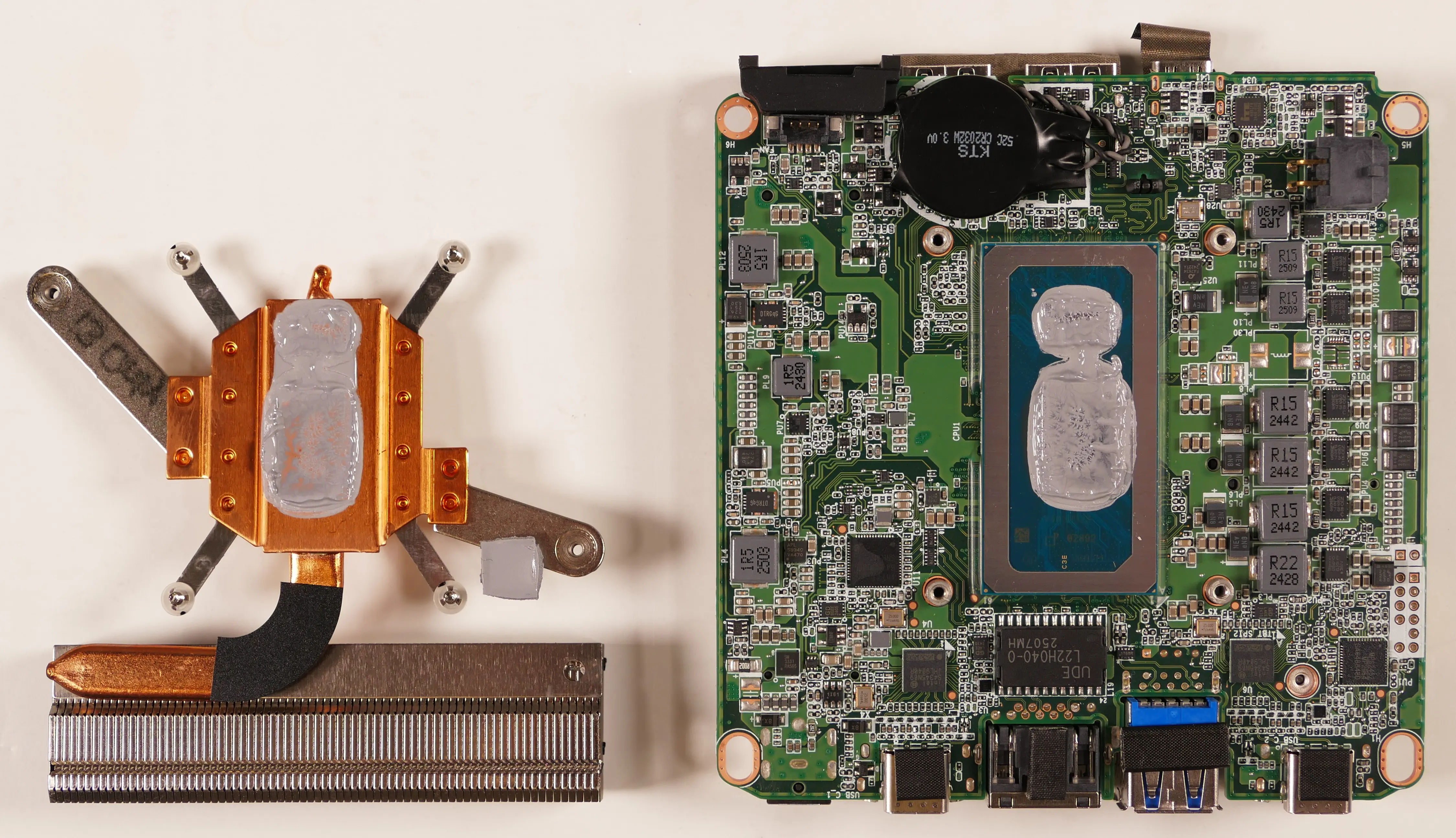
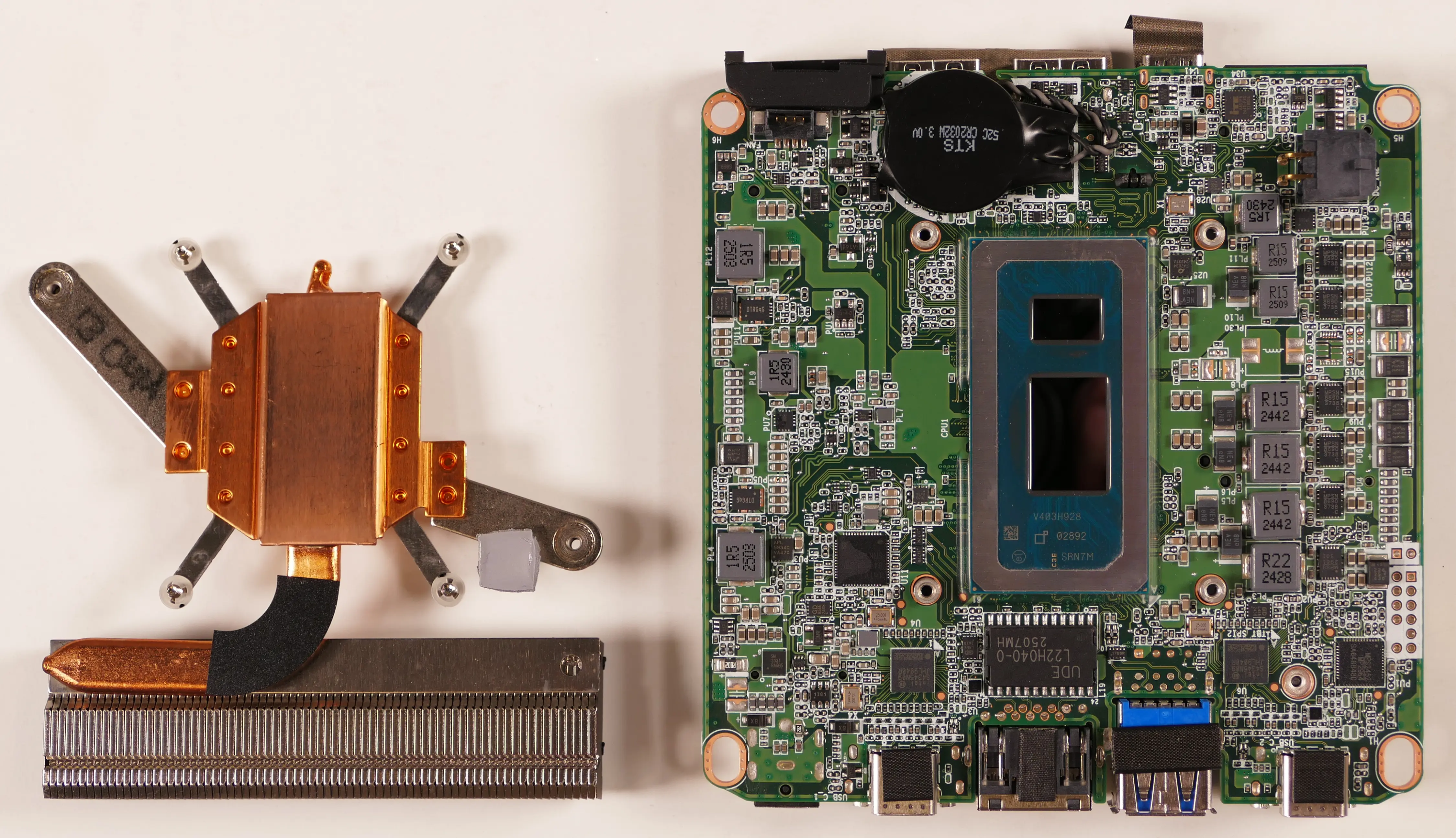
- Apply a small line of thermal paste directly onto each of the CPU chips.

- Replace the heatsink and tighten the four screws in the order of the stamped numbers (starting with #1, then #2, and continuing until #4).
- For easier installation, partially tighten each screw first, then fully tighten them in the same numbered order.
- Reinstall the fan, reinstall the motherboard, reconnect the wireless card, reinstall the M.2 drive in Slot 1 (if necessary), reinstall the expansion slot (or placeholder), close the bottom panel, and reinstall the top cover.
Installing the cable keeper:
Your Meerkat comes with an optional cable organizer to help hold cables in place.
Tools required: Cross-head (Phillips) screwdriver (optional)
Time estimate: 1 minute
Difficulty: Easy ●
Steps to install the cable keeper:
- Screw the Phillips thumbscrew on the cable keeper into the back of the Meerkat.
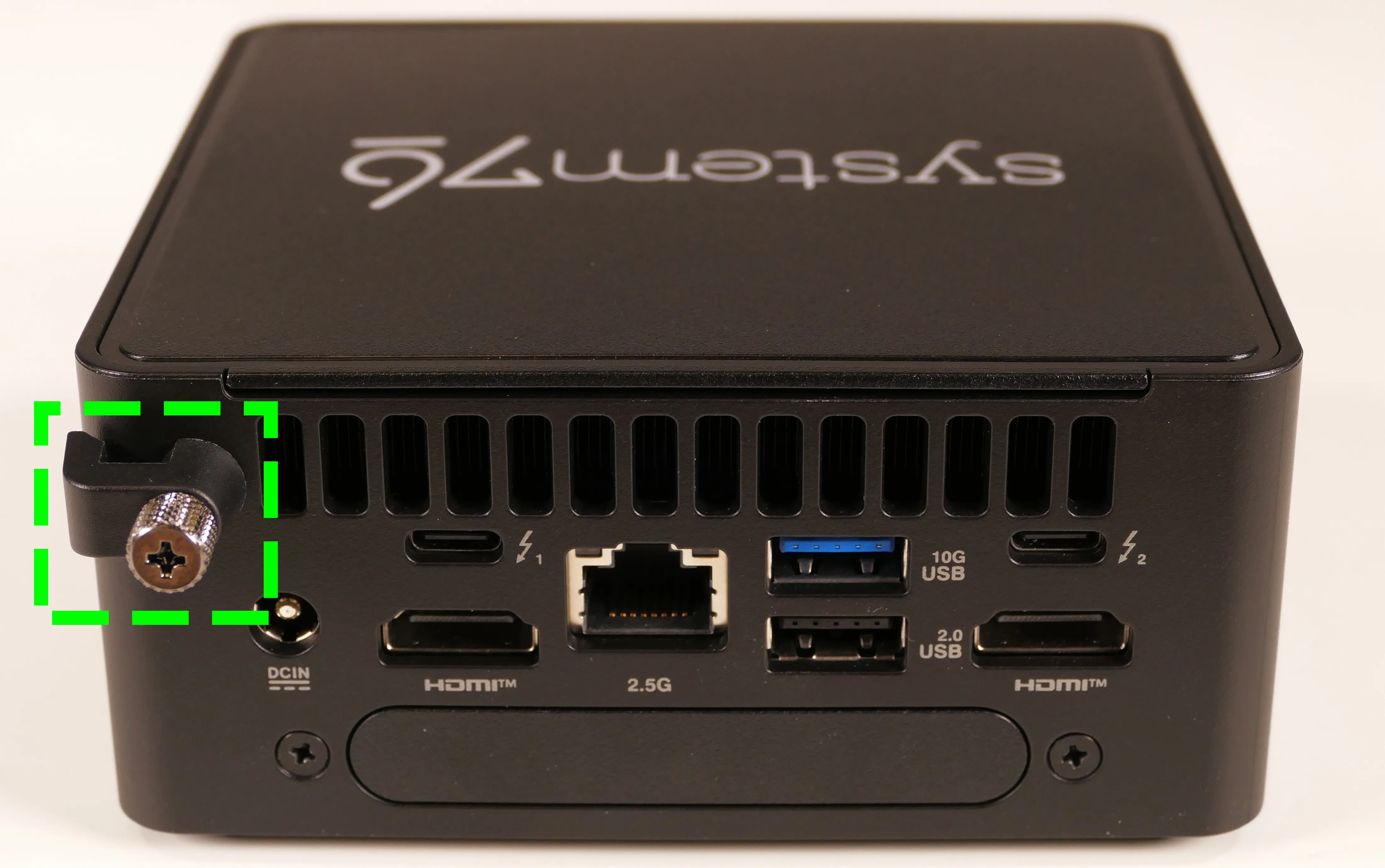
Mounting with the VESA adapter:
Your Meerkat comes with a VESA mount adapter, which allows it to be mounted on the back of a display. This allows operation as an all-in-one, taking up no additional desk space.
Because the Meerkat mounts to the display's VESA mount, this will only work on displays which aren't already mounted via the VESA mount.
Tools required: Cross-head (Phillips) screwdriver
Time estimate: 10 minutes
Difficulty: Easy ●
Steps to mount with the VESA adapter:
- Insert the two shoulder screws into the bottom of the Meerkat.
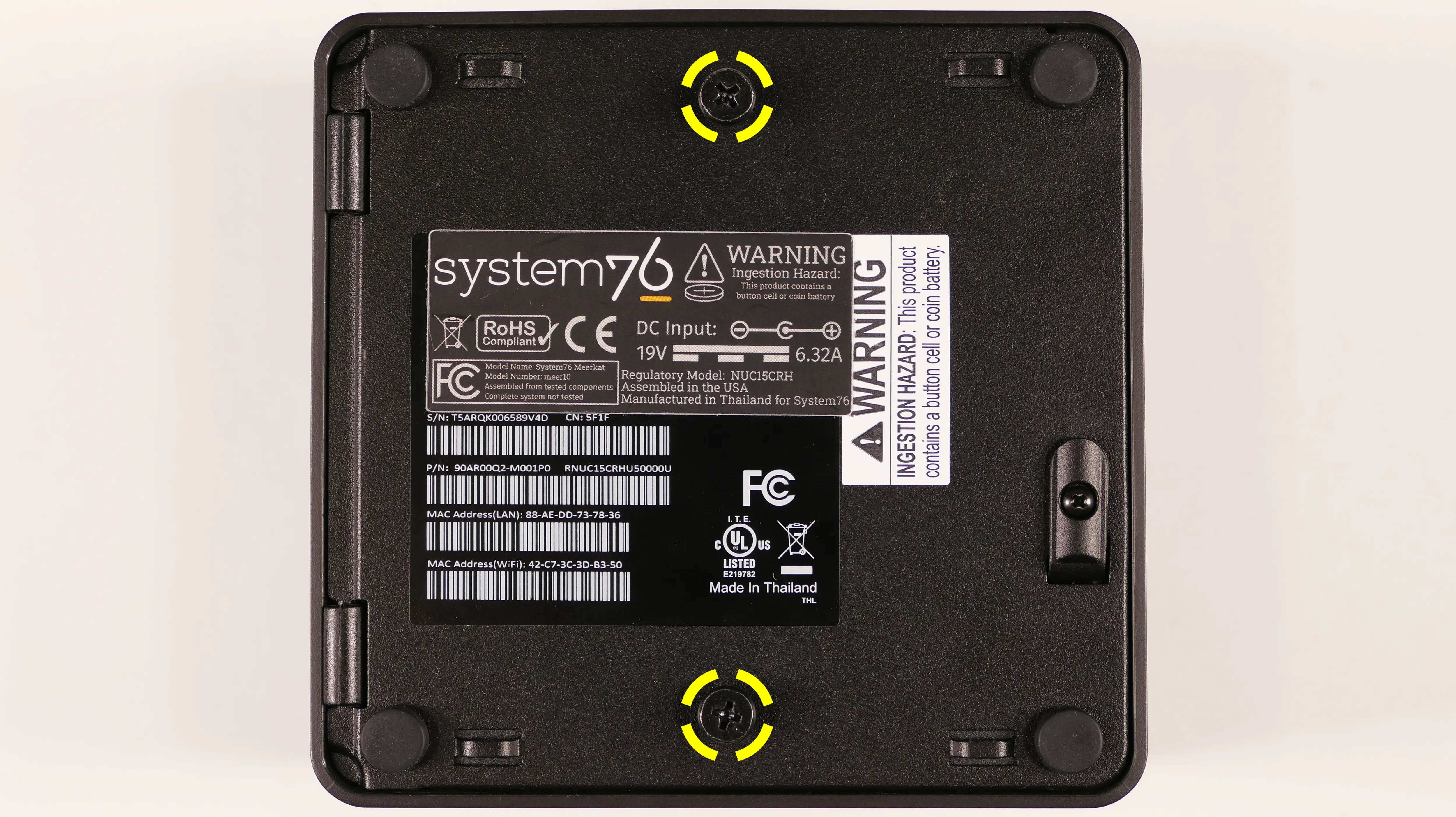
- Use the remaining four screws to attach the VESA mounting plate to the display, using the arrow to guide the orientation.
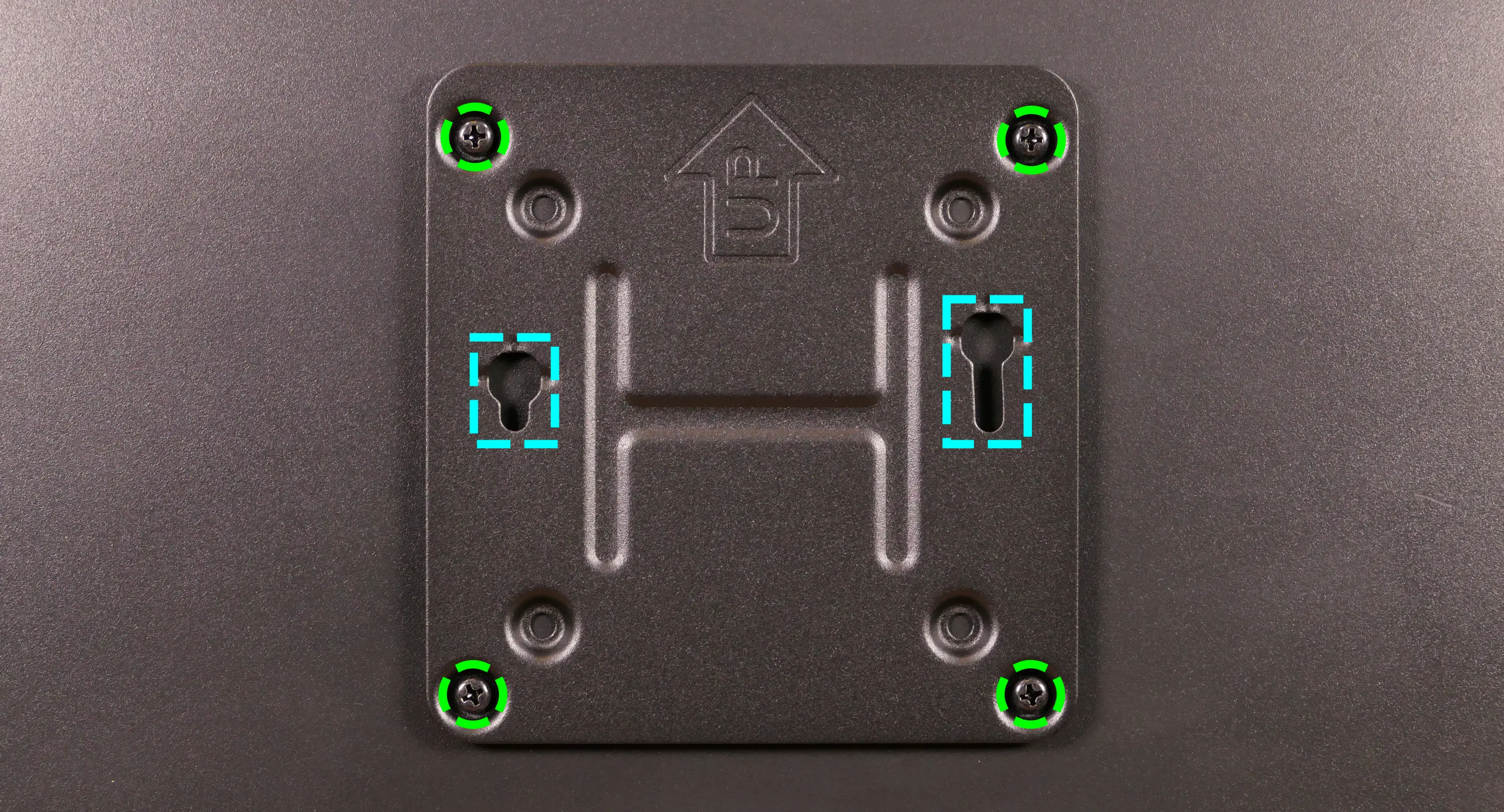
- Insert the two shoulder screws in the Meerkat into the two holes in the mounting plate (highlighted cyan above), then set the Meerkat down so it hangs on the mounting plate.
- The Meerkat hangs sideways and can be mounted in either direction.
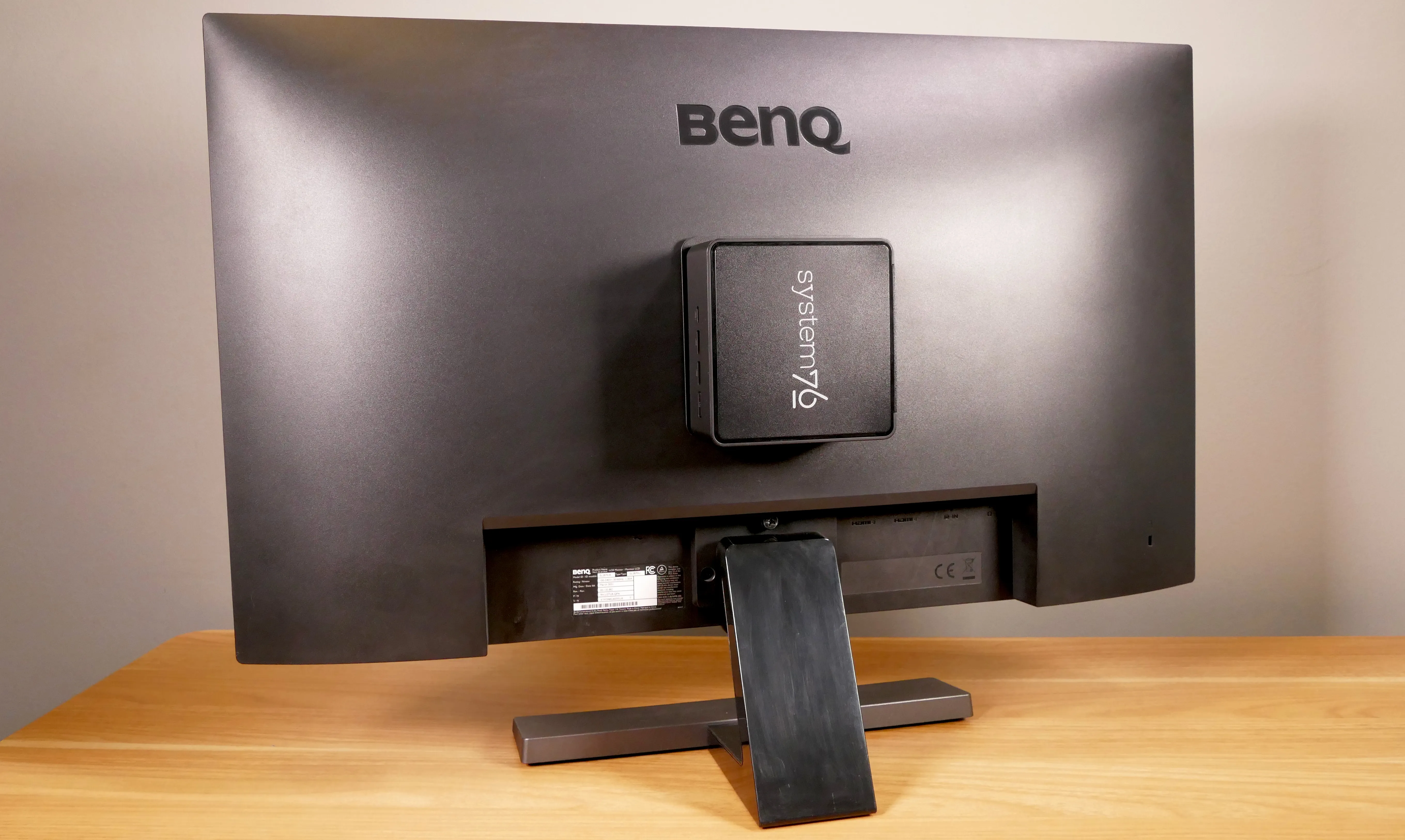
nebula19 (nebula19-1)
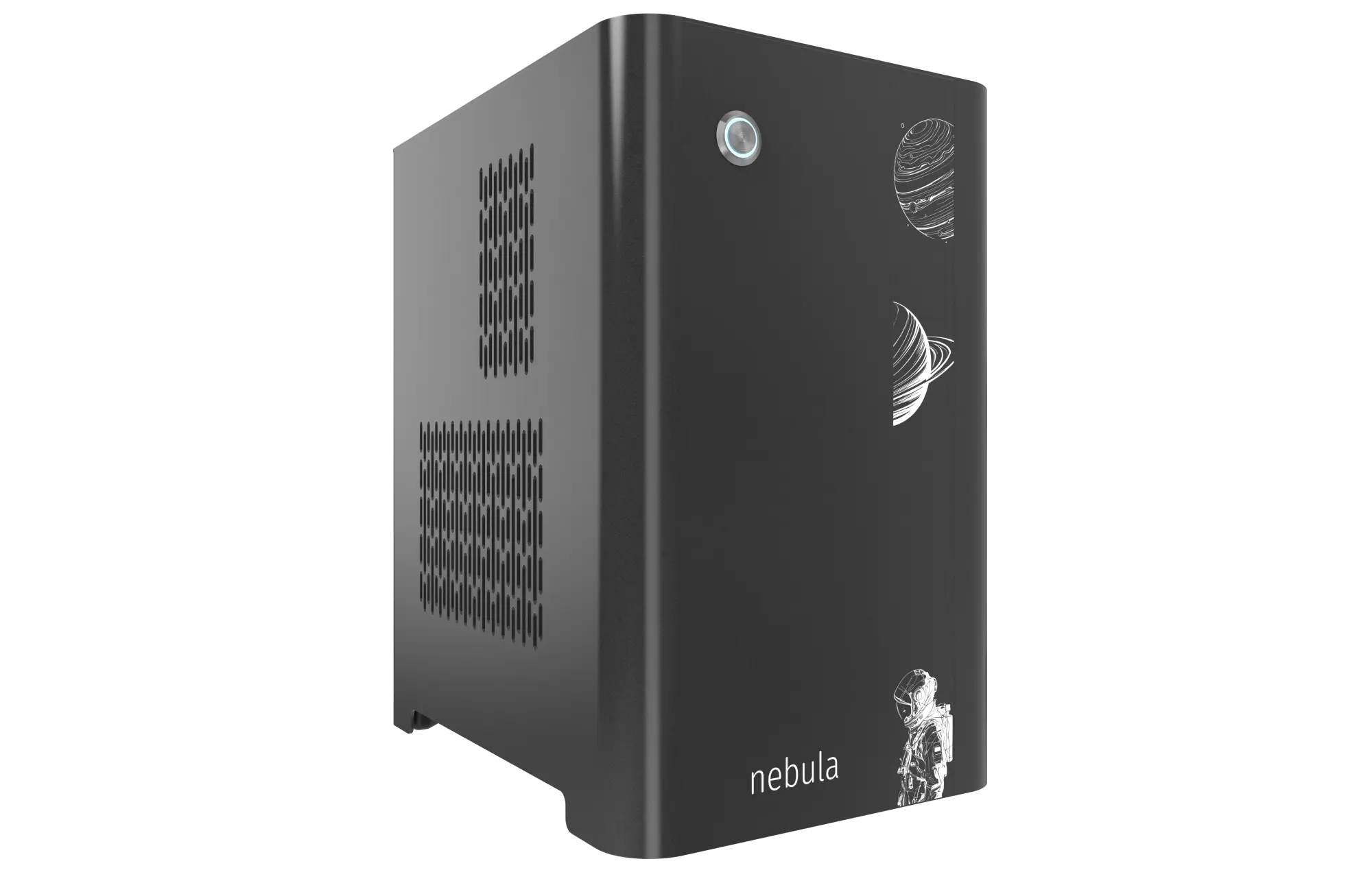
The System76 nebula19 is a desktop chassis (for DIY builds) with the following specifications:
- Dimensions
- Size: 32.7cm × 20.7cm × 29.1cm
- Volume: 19 litres
- Motherboard sizes
- Mini-ITX
- GPU compatibility
- Internal clearance: 278.175mm
- Recommended maximum length: 268.175mm
- Cooling capacity
- 2x 92mm CPU fans
- Rear exhaust fan: Be Quiet!
PUW2-9225-MR-PWM - CPU cooler:
- Optional included cooler:
- After April 2024: Be Quiet! Pure Rock Slim 2 (
BK030)- Included cooler fan: Be Quiet!
PUW2-9225-MR-PWM
- Included cooler fan: Be Quiet!
- Before April 2024: Noctua
NH-U9S- Included cooler fan: Noctua
NF-A9 PWM
- Included cooler fan: Noctua
- After April 2024: Be Quiet! Pure Rock Slim 2 (
- Max dimensions:
- Height (top to bottom of duct): 106mm
- Width (motherboard to side of duct): 133mm
- Length (front to back within duct): 125mm (104mm with fans)
- Optional included cooler:
- Rear exhaust fan: Be Quiet!
- 1x 140mm bottom intake fan: Be Quiet!
SIW4-14025-LF-PWM - 1x 120mm side intake fan (optional add-on): Be Quiet!
SIW4-12025-MF-PWM
- 2x 92mm CPU fans
- Daughterboards
- Nebula Io power button controller board
- MYS7523 Rev. 2.0 front I/O board
- Thelio Io SATA 2.5" drive backplane (optional add-on)
nebula19 (External Overview)
Front/back overview:
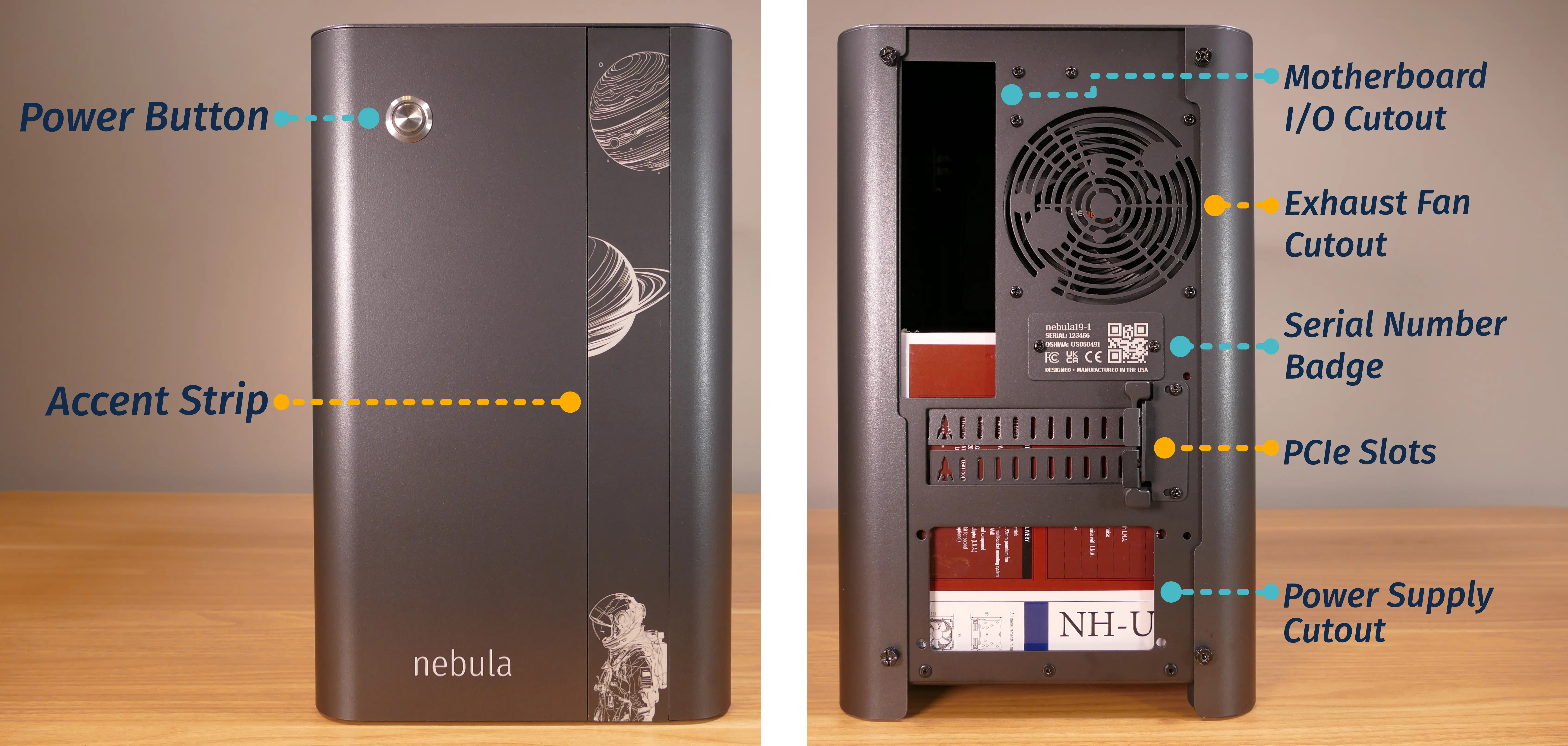
Left/right side overview:
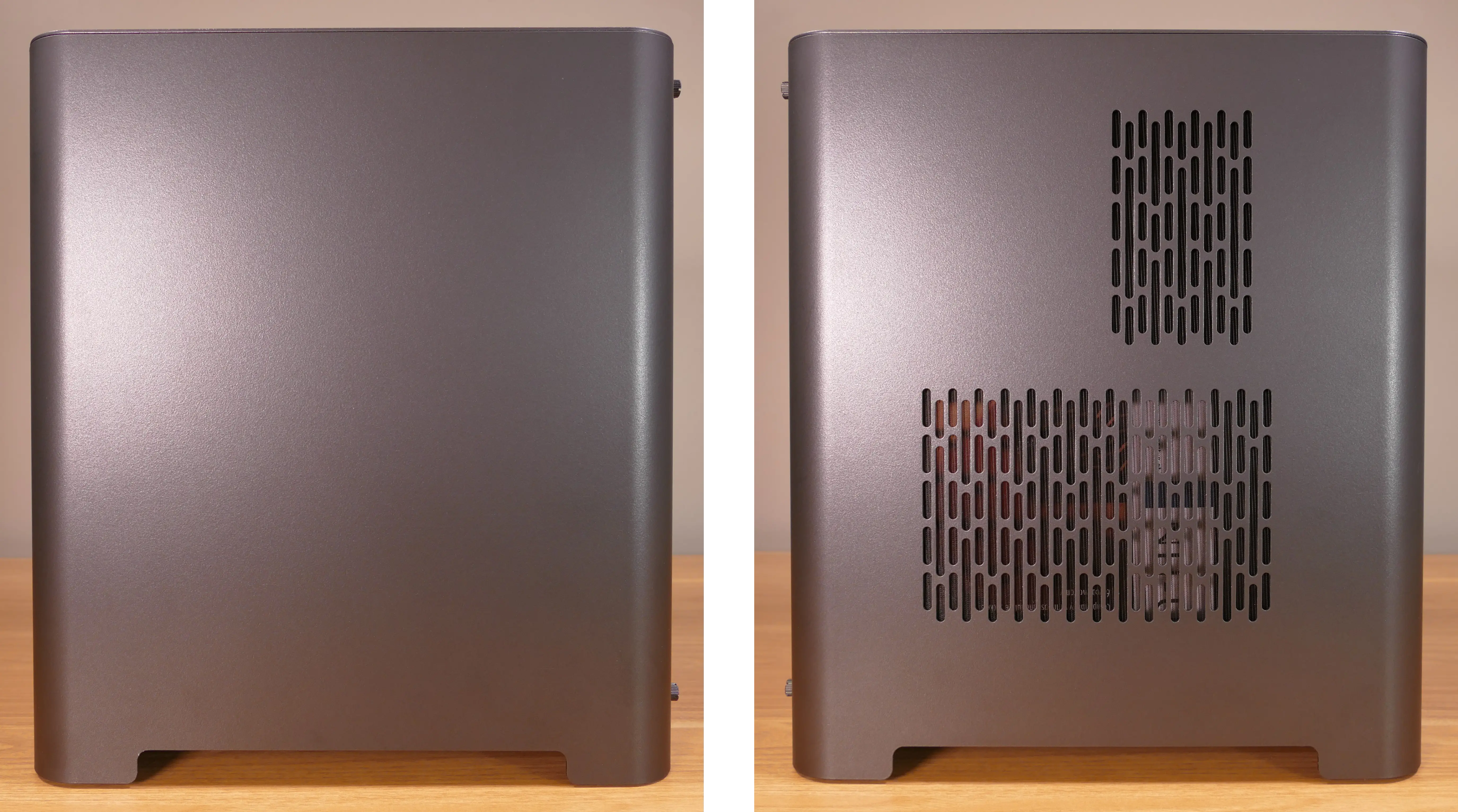
Top/bottom overview:
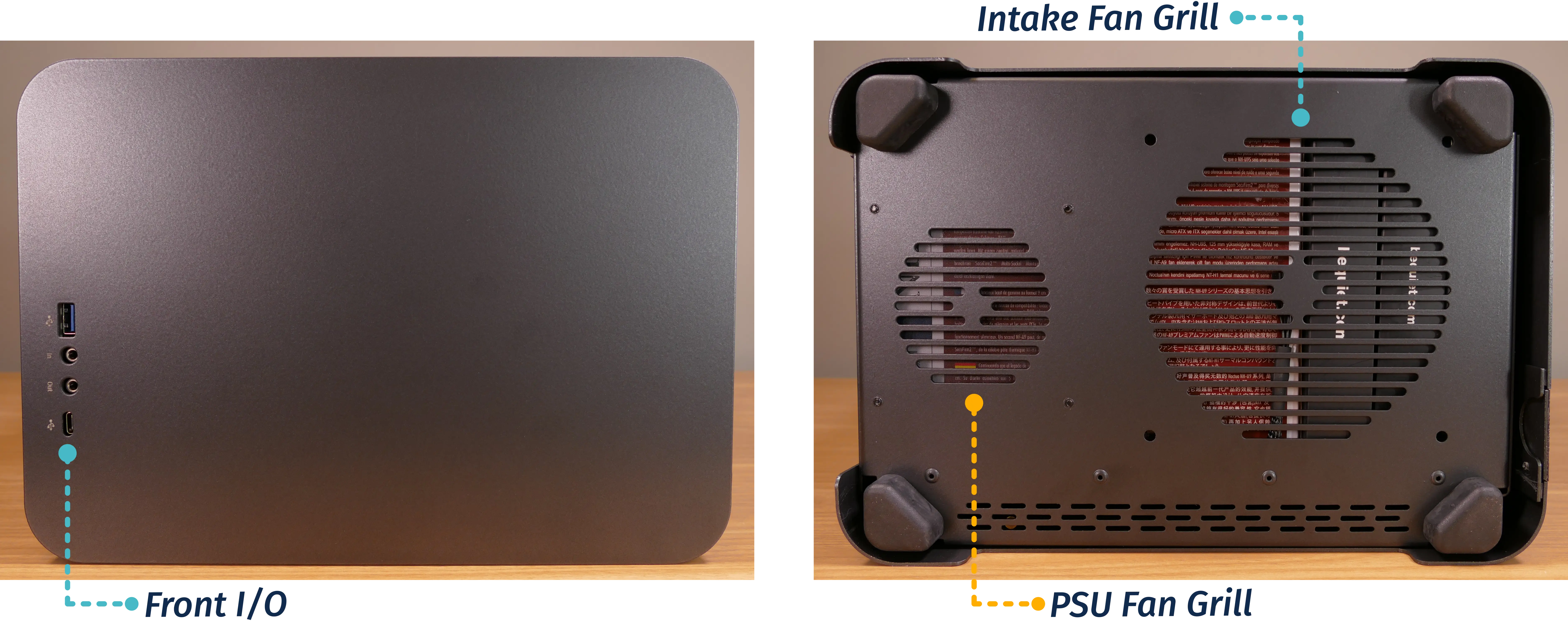
nebula19 (Parts & Assembly)
The nebula19 chassis is ready to be outfitted with standard personal computer components. If the system has already been built, ensure the system is powered off and all cables are unplugged from the motherboard, PCIe cards, power supply, and front I/O before opening the chassis.
The preinstalled velcro strips are left partially unwrapped to aid in removal. When building the system, you can optionally wrap the velcro up the rest of the way.
- Replacing the front accent strip
- Removing the top case
- Removing the CPU duct
- Unpacking the included accessories
- Installing/removing the side fan bracket
- Installing the motherboard
- Installing the CPU duct fans
- Installing the GPU
- Installing the SATA backplane
- Installing 2.5" drives
- Installing the bottom case fan
- Installing side intake fan
- Installing the power supply
- Wiring the front I/O and power button
Replacing the front accent strip:
nebula19 includes a customizable accent panel on the front of the case, which can be swapped to change the case's look and feel. The instructions for swapping the accent are also available in video form.
- Tools required: None
Steps to replace the front accent strip:
- Place the nebula19 on the edge of the desk so the front side is hanging off of the desk.
- The nebula19 can alternatively be lifted or tilted so the front of the computer is hovering above the desk.
- Slide the accent strip down to unlock it.
- The accent can be gripped at the bottom edge.
- Pull the accent strip off of the case, starting with the bottom edge.
- Place the new accent strip onto the front of the case and slide it up to lock it into place.
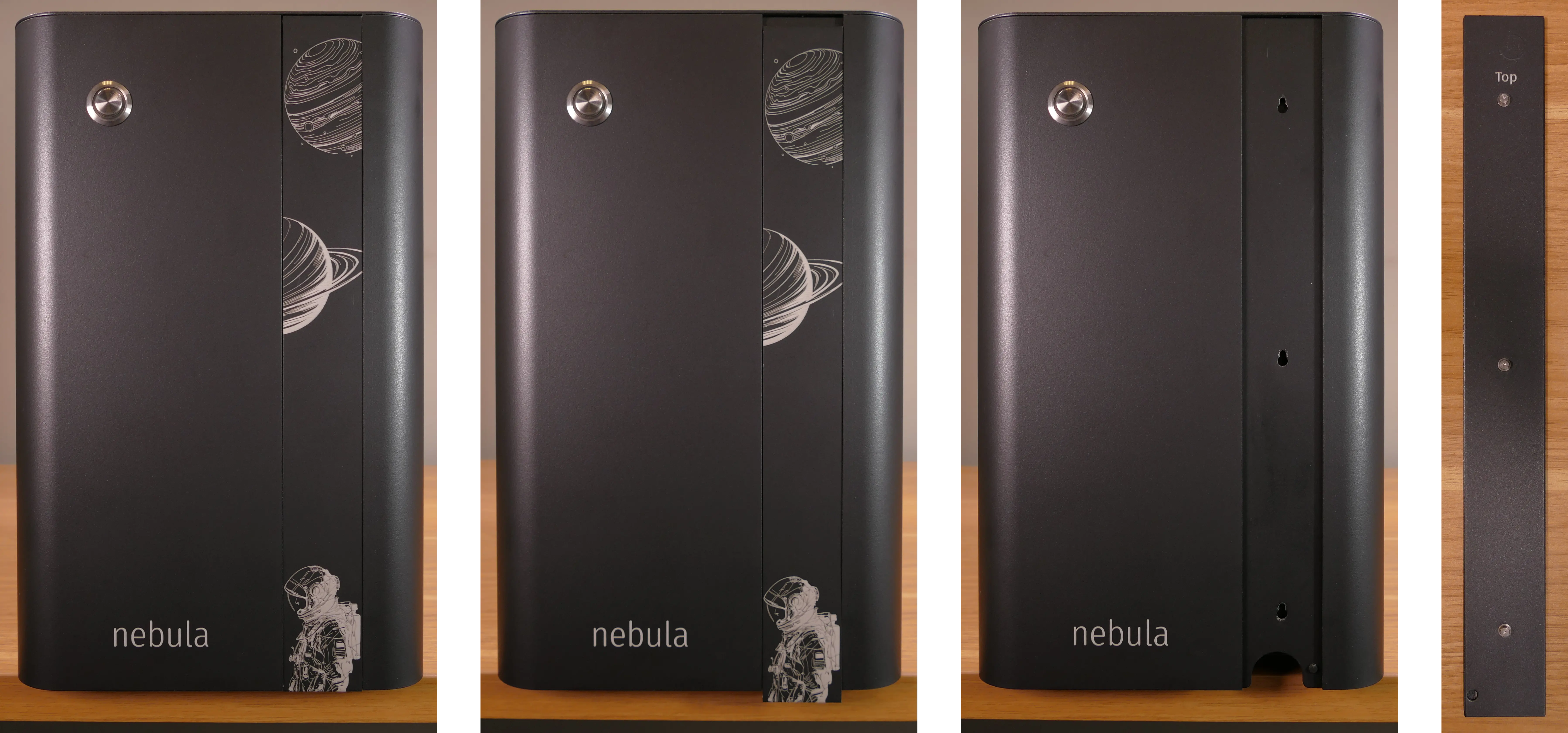
Removing the top case:
The top case can be removed to access the internal components.
- Tools required: Cross-head (Phillips) screwdriver (optional)
Steps to remove the top case:
- Remove the four outer screws holding the top case onto the machine.
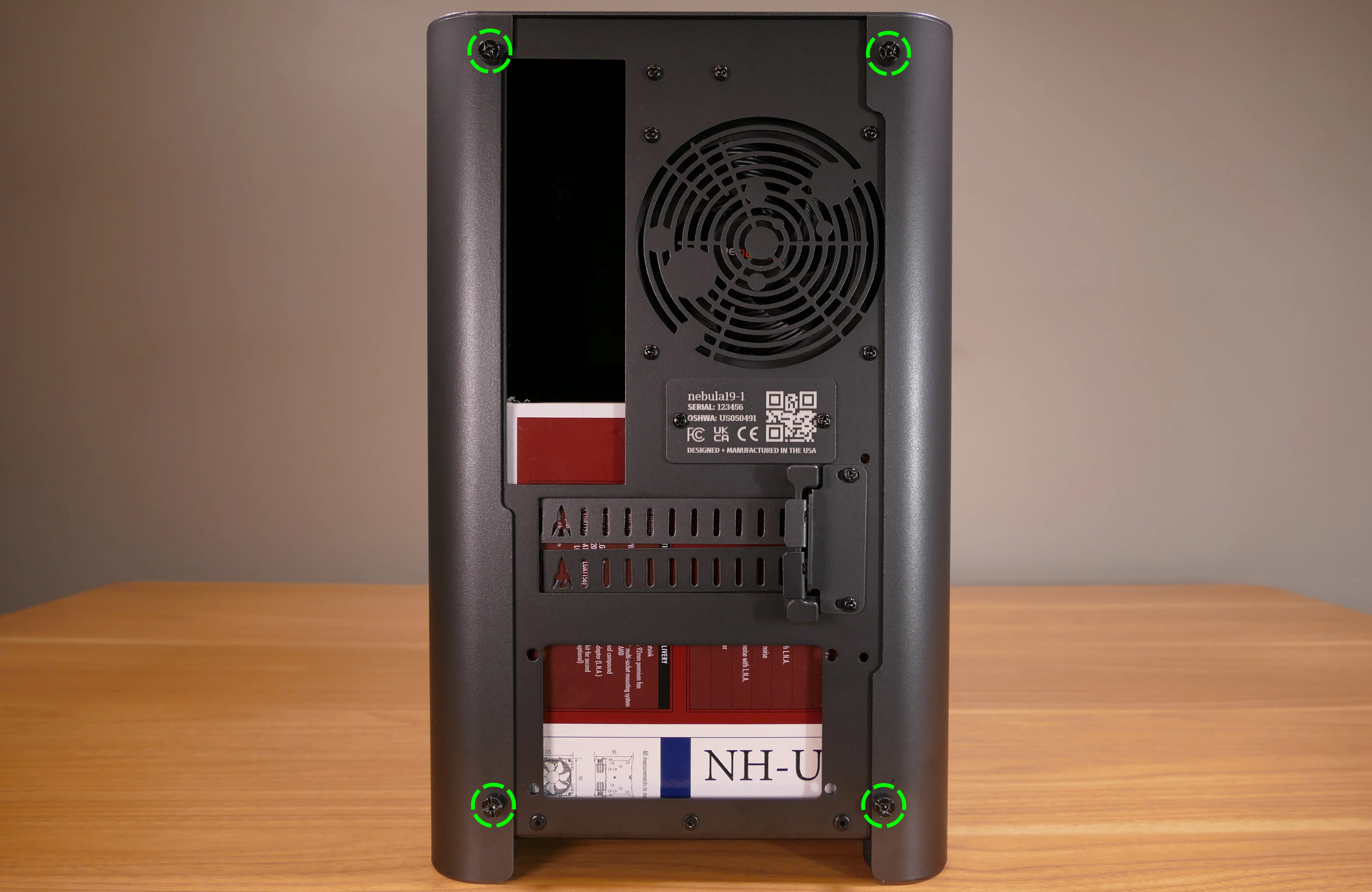
- Slide the top case up and off of the machine.
Removing the CPU duct:
The CPU duct supports one or more of the CPU fans and guides airflow from the side of the case through the CPU radiator to the back exhaust vent. The CPU duct is custom-designed to work with the Noctua NH-U9S CPU cooler (before April 2024) or the Be Quiet! Pure Rock Slim 2 BK030 (after April 2024) that's optionally included with nebula19.
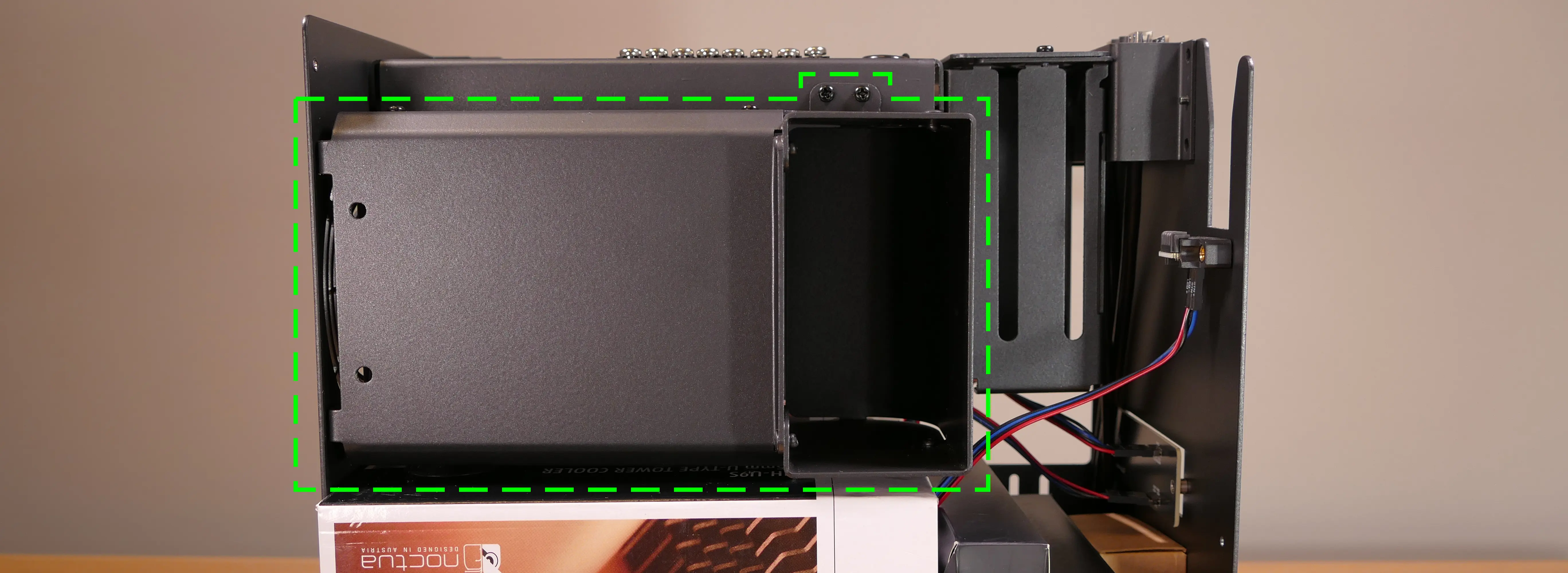
- Tools required: Cross-head (Phillips) screwdriver
Steps to remove the CPU duct:
- Follow the steps above to remove the top case.
- Unscrew the two side screws holding the CPU duct onto the top crossbar.
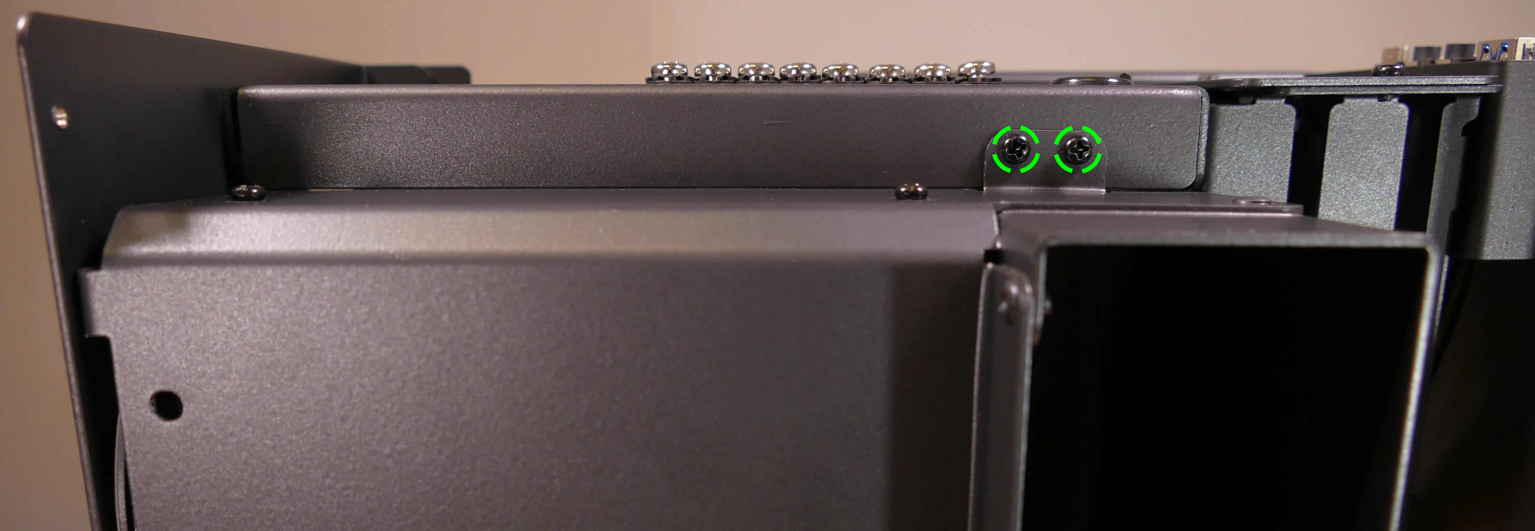
- Unscrew the four back screws holding the CPU duct onto the chassis.
- Hold onto the duct while removing the final screw so it doesn't fall.
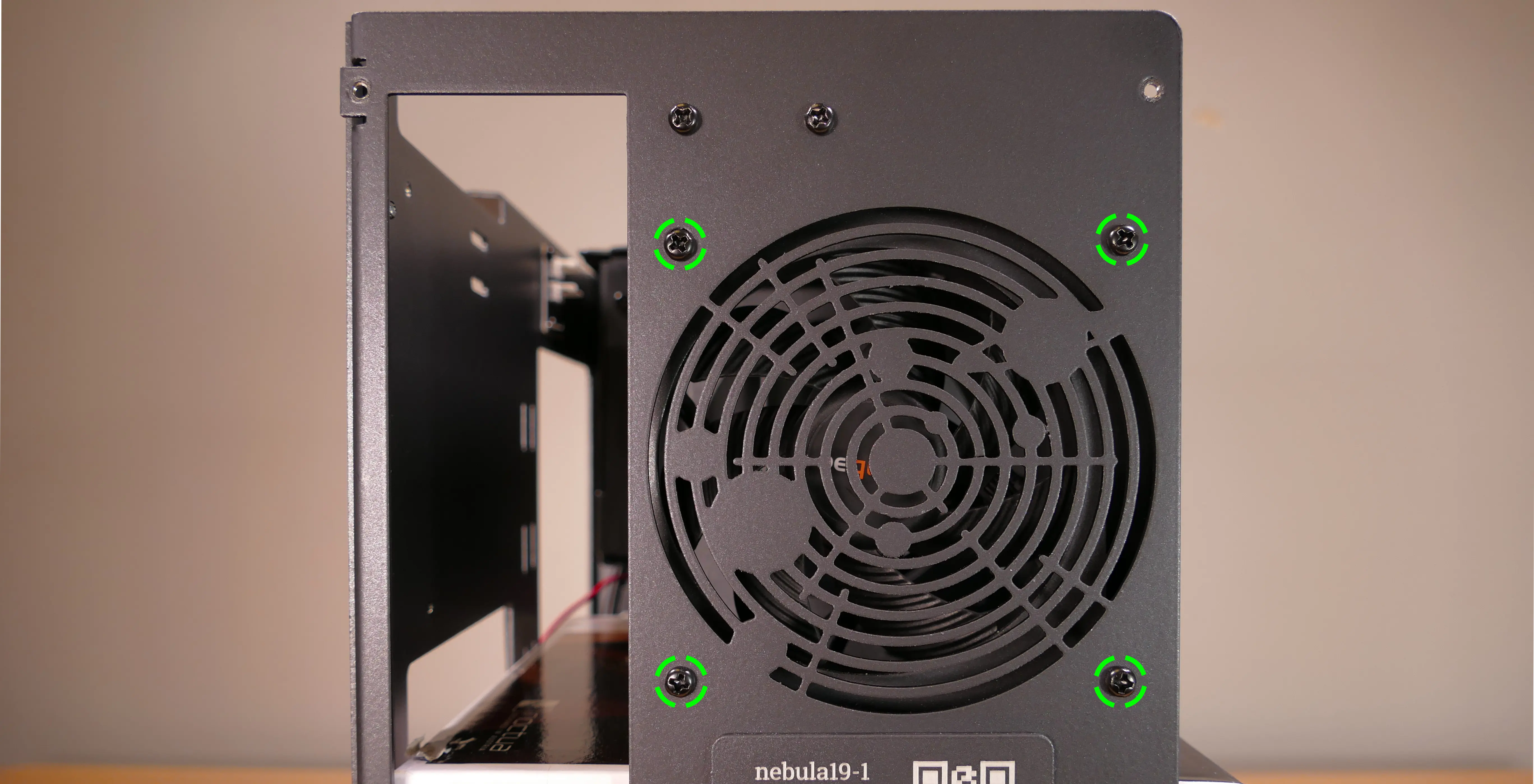
- Pull the CPU duct out of the chassis.
- When replacing the CPU duct, ensure all fan cables are plugged into the fan splitter board in the top right of the chassis.
Unpacking the included accessories:
nebula19 includes the following components preinstalled:
- 1x
nebula_iopower button controller board - 1x
MYS7523top I/O board - 2x four-pin fan splitter boards
- 1x back CPU duct fan
- Be Quiet! Pure Wings 2 92mm (
BQ PUW2-9225-MR-PWM)
- Be Quiet! Pure Wings 2 92mm (
- 2x short velcro straps
- 1x on the side of the chassis
- 1x on the side fan bracket
In addition, nebula19 ships with the following non-installed accessories:
- 1x Screw and velcro box
- 8x short velcro straps
- 1x long velcro strap
- 4x motherboard standoffs
- 4x M3 (motherboard) screws
- 4x fan screws
- 1x Bottom case fan
- Be Quiet! Silent Wings 4 140mm (
BQ SIW4-14025-LF-PWM)
- Be Quiet! Silent Wings 4 140mm (
- 1x CPU cooler w/ fan (optional)
- After April 2024: Be Quiet! Pure Rock Slim 2 (
BK030) w/ Pure Wings 2 92mm (BQ PUW2-9225-MR-PWM) - Before April 2024: Noctua
NH-U9Scooler w/NF-A9 PWMfan
- After April 2024: Be Quiet! Pure Rock Slim 2 (
- 1x Side bracket fan (optional)
- Be Quiet! Silent Wings 4 120mm (
BQ SIW4-12025-MF-PWM)
- Be Quiet! Silent Wings 4 120mm (
Steps to unpack the included accessories:
- Follow the steps above to remove the top case and remove the CPU duct.
- Remove the accessory boxes from the chassis.
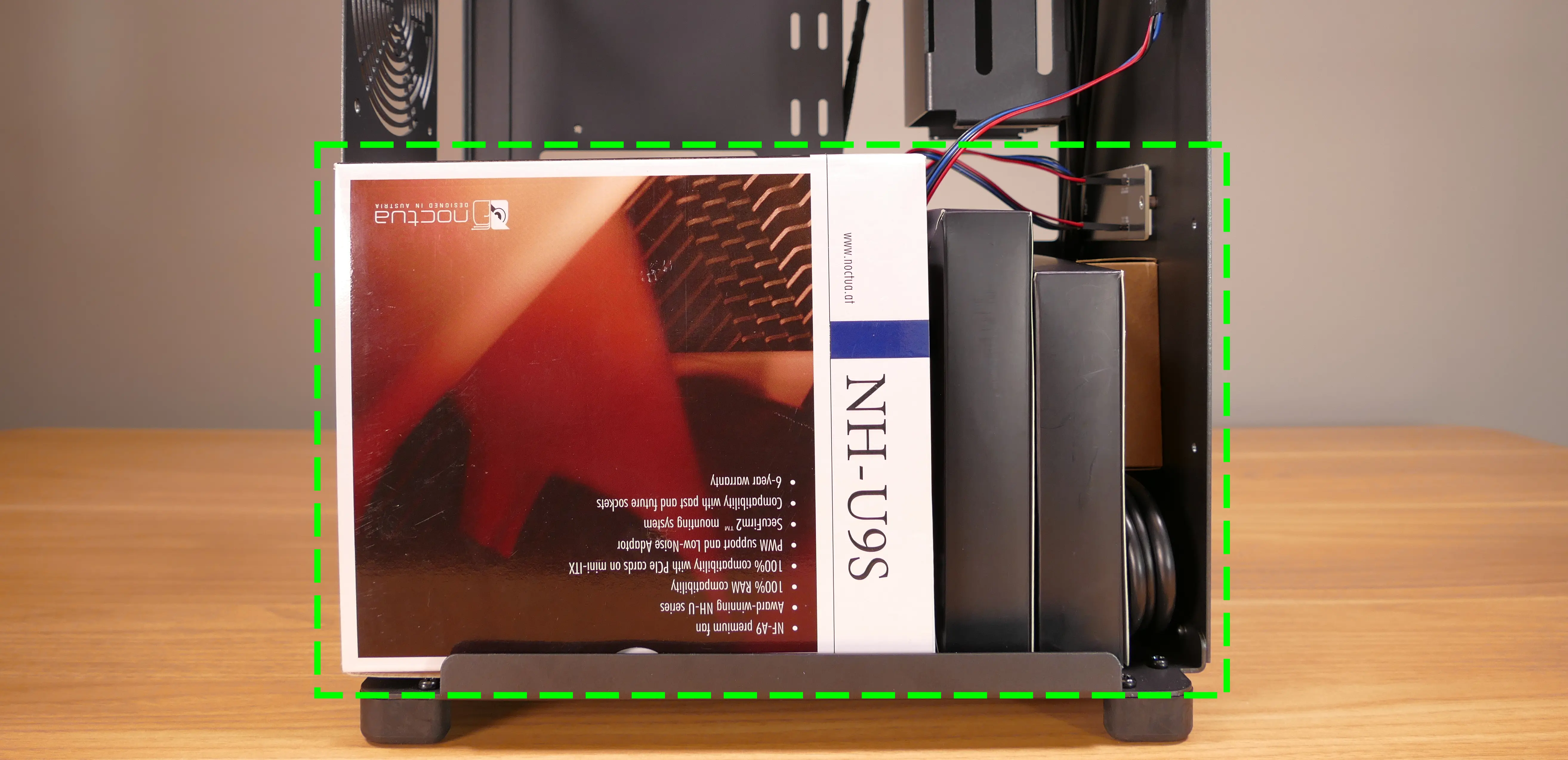
- Open the accessory boxes as needed.
Installing/removing the side fan bracket:
The side fan bracket provides a mounting point for an extra intake fan, such as the optional BQ SIW4-12025-MF-PWM.
If no optional accessories were ordered with the nebula19, then the side fan bracket will ship preinstalled. If optional accessories were included in the order, then they will ship inside of the chassis, and the side fan bracket will ship in a separate box. It can be installed after assembling the rest of the computer.
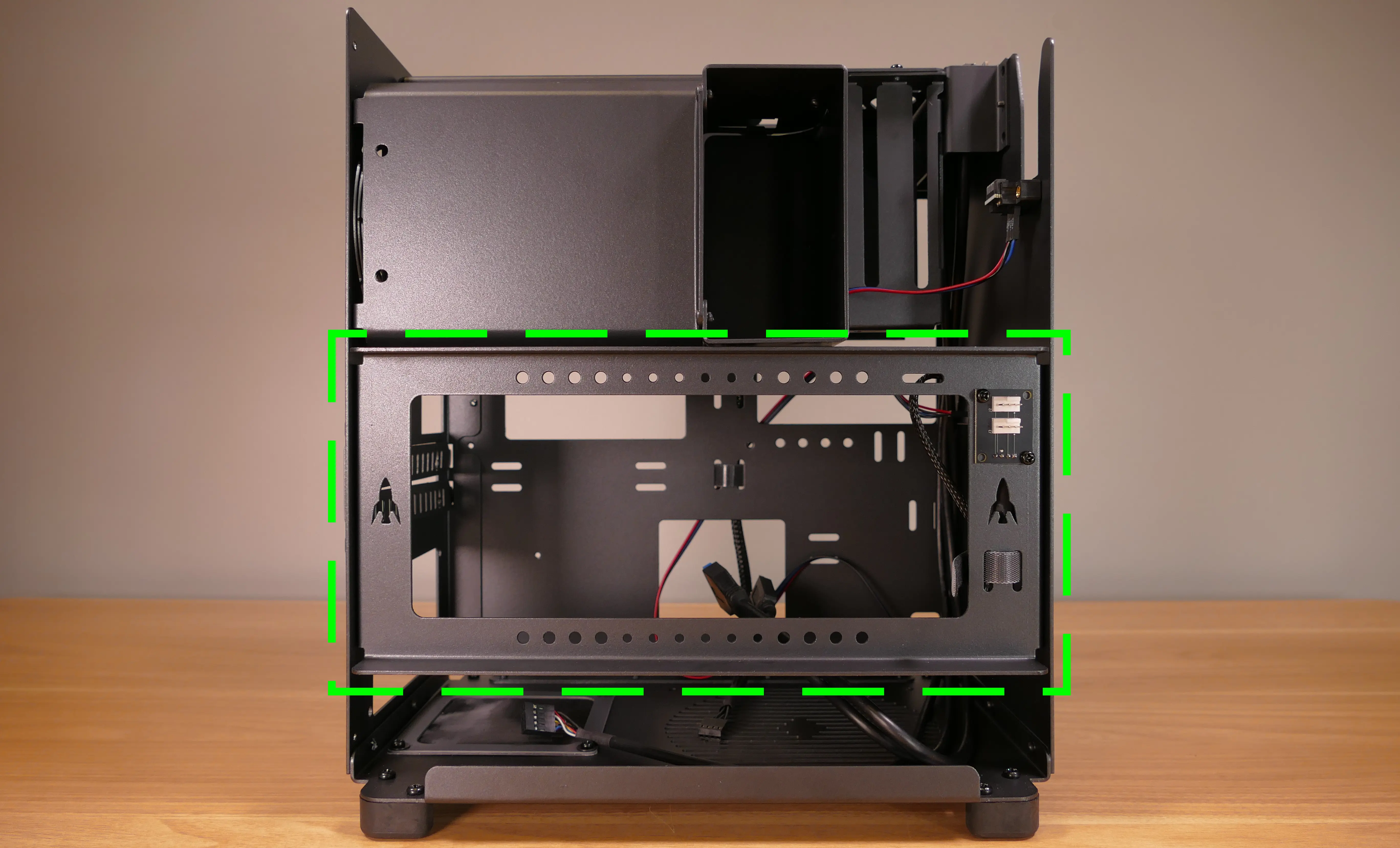
The fan splitter on the side fan bracket can be used for the side intake fan installed on the side fan bracket as well as the bottom chassis intake fan.
- Tools required: Cross-head (Phillips) screwdriver
Steps to unpack and install the side fan bracket:
- Remove the top case and unpack the included accessories.
- Cut the tape of the side fan bracket box and remove the side fan bracket and screw bag from the box.

- Screw the side fan bracket into the system using the four M3 screws included with the side fan bracket.
- The fan splitter board should be on the right side (with the dual headers facing outwards) and the rockets should point upwards.
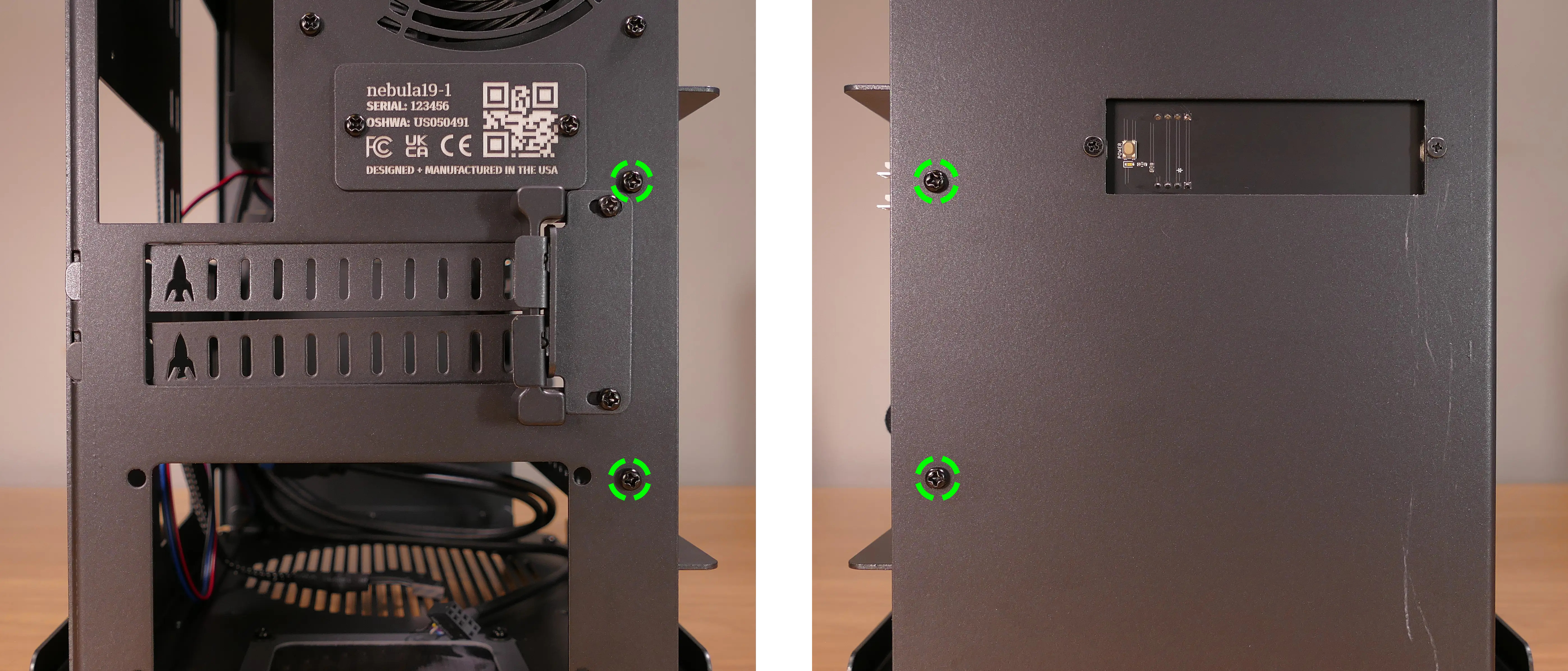
Steps to remove the side fan bracket:
- Remove the top case.
- Unscrew the four screws holding the side fan bracket in place (two on the front of the case, two on the back.)

- Pull the side fan bracket out of the chassis.
Installing the motherboard:
nebula19 supports the following standard motherboard sizes:
- Mini-DTX
- Mini-ITX
Four standoffs and motherboard screws are included.
- Tools required: Cross-head (Phillips) screwdriver
Steps to install the motherboard:
- If they are installed, remove the top case, remove the CPU duct and remove the side fan bracket.
- Locate the standoffs and M3 screws from the brown screw and velcro box.
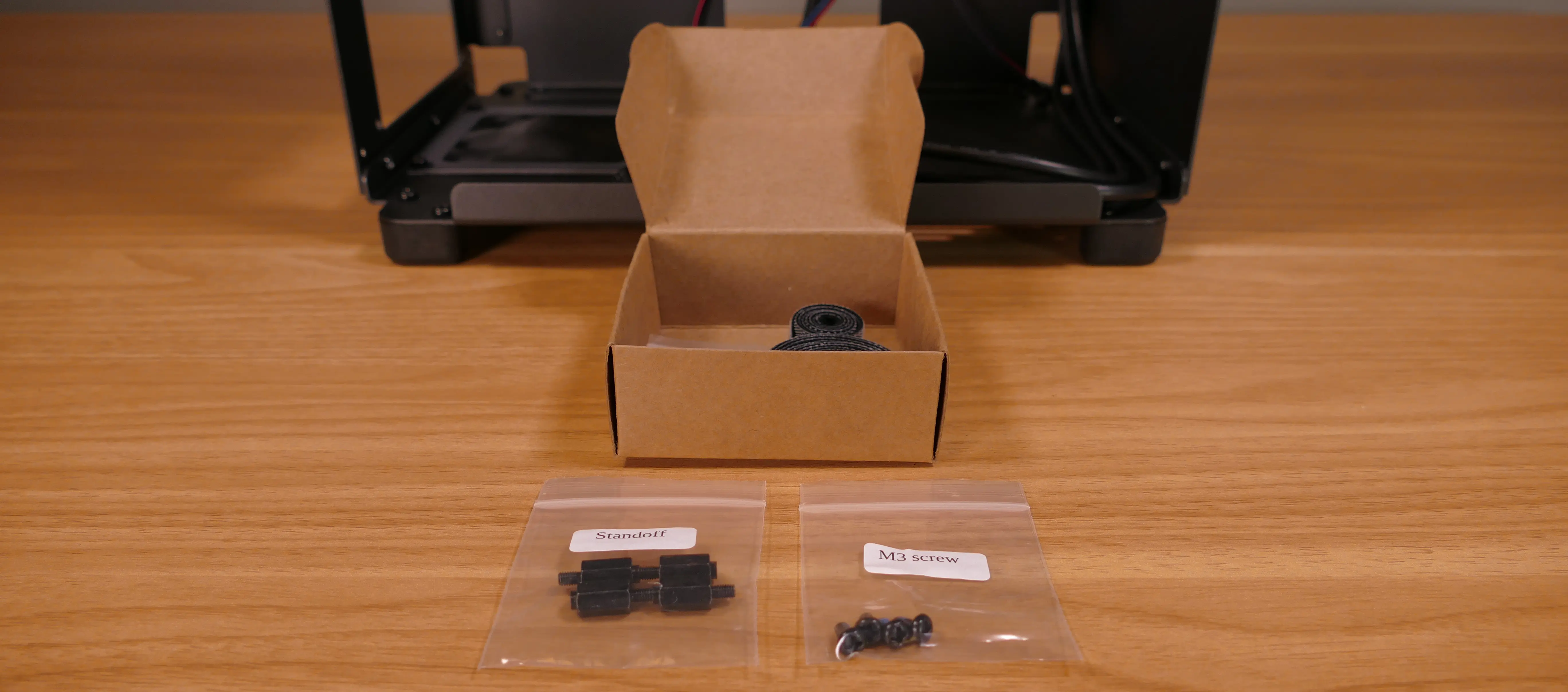
- Insert the four standoffs into the holes in the chassis.
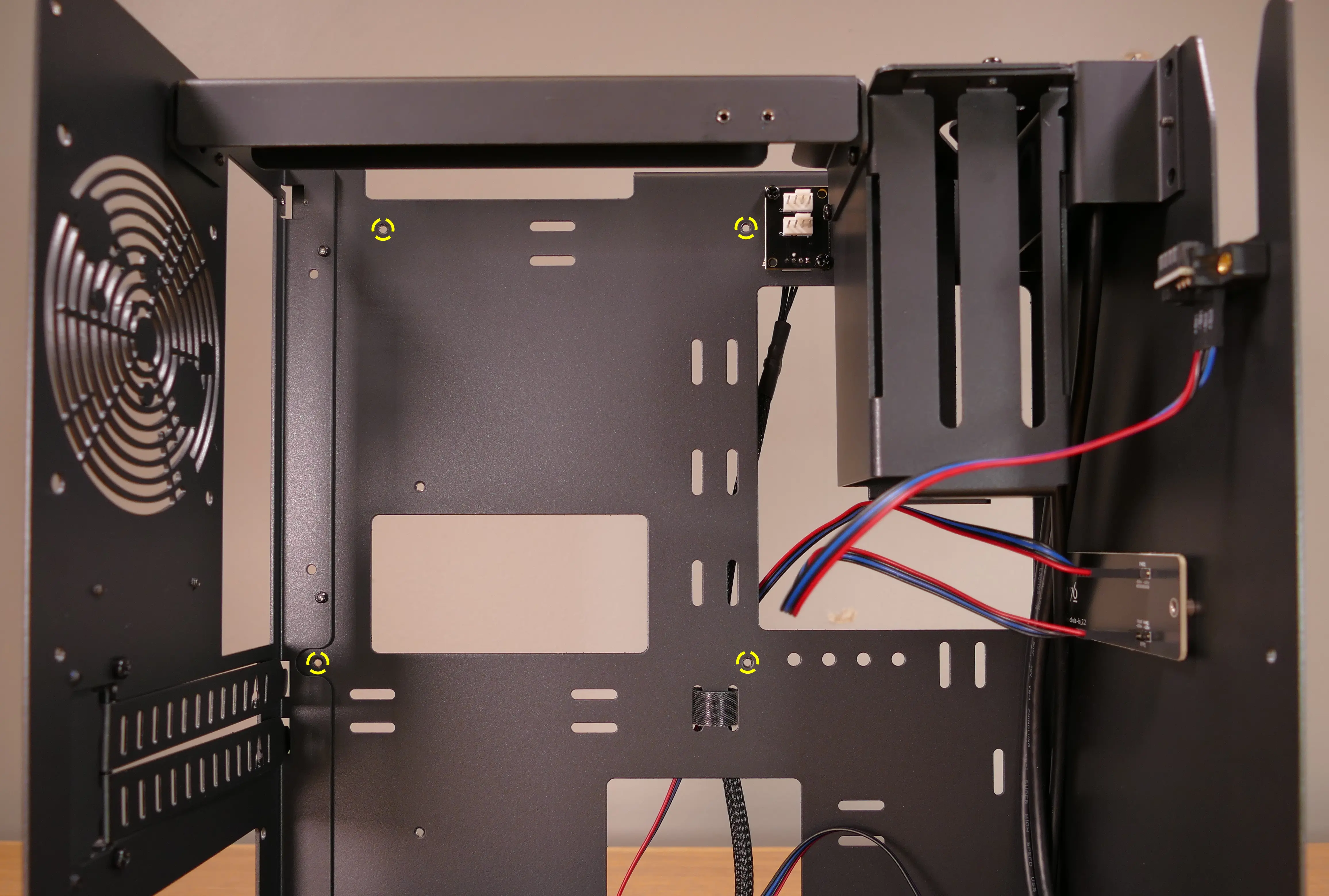
- Install the motherboard's I/O shield onto the back of the chassis by pressing it into place from the inside.
- Place the motherboard into the chassis, aligning the motherboard's screw holes with the installed standoffs.
- Screw the motherboard into the standoffs using the M3 screws.
Installing the CPU duct fans:
nebula19 ships with one 92mm fan (BQ PUW2-9225-MR-PWM) installed in the back of the CPU duct. If you install a CPU cooler with its own 92mm fan, such as the optional Be Quiet! Pure Rock Slim 2 BK030 or Noctua NH-U9S coolers sold with nebula19 (which include an additional BQ PUW2-9225-MR-PWM fan or a Noctua NF-A9 PWM fan, respectively), then the CPU cooler's fan can be mounted in the front of the CPU duct.
These instructions use the Noctua NH-U9S as an example.
- Tools required: Cross-head (Phillips) screwdriver
Steps to install the CPU cooler fan (front):
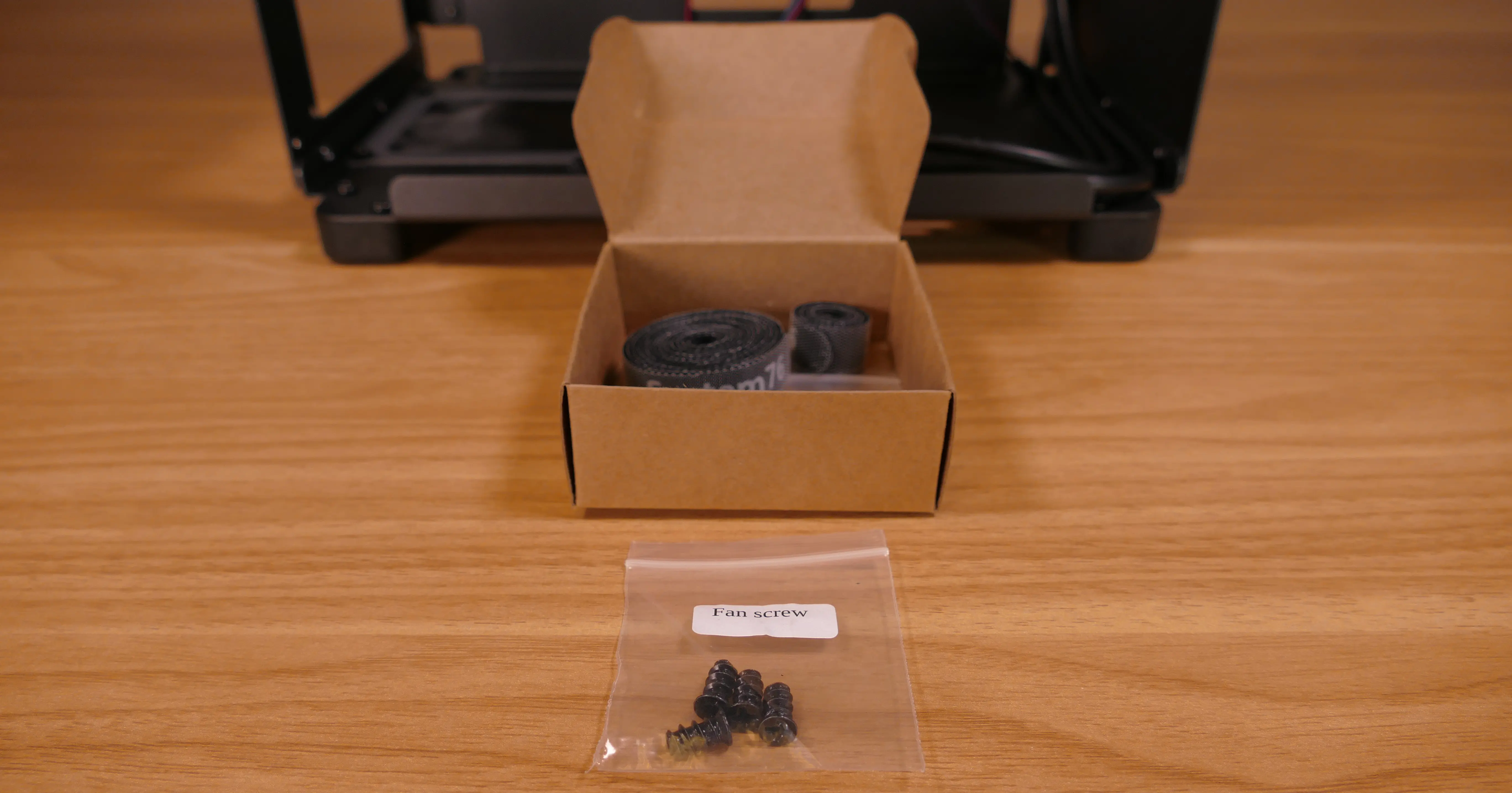
- Remove the
NH-U9Sfrom the box.
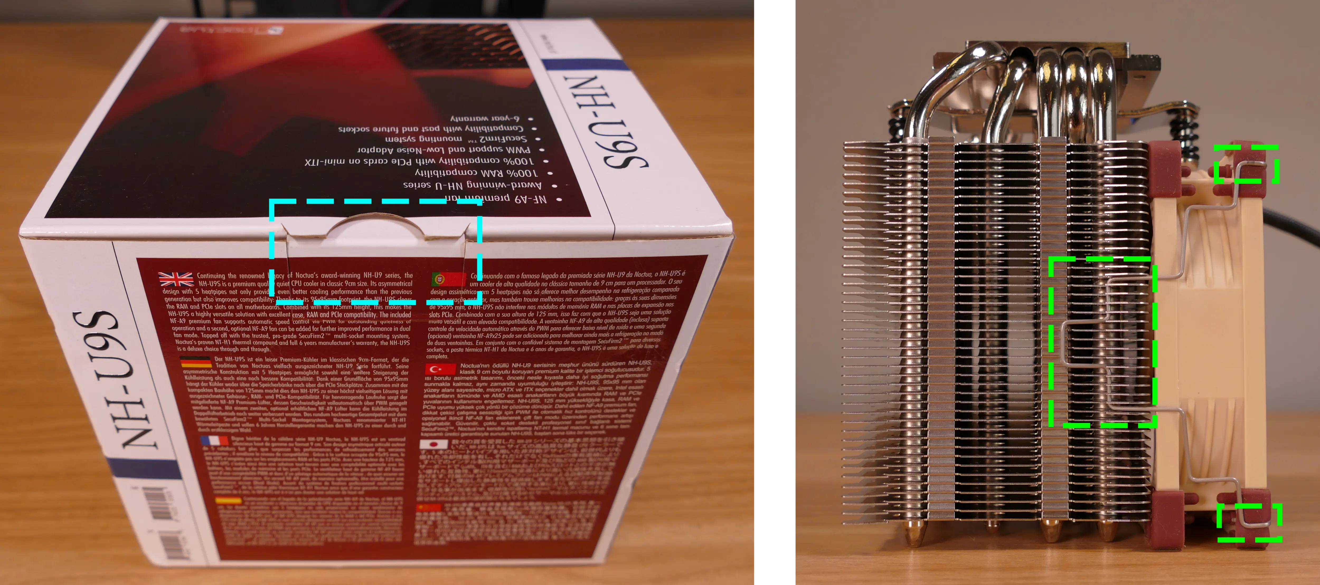
- Remove the included
NF-F12fan from the cooler heatsink by pulling the metal tabs (highlighted green above) off of the heatsink and fan. - Install the cooler onto the motherboard/processor.
- Remove the front fan bracket from the CPU duct by unscrewing the four screws (highlighted green below) and pulling it out of the CPU duct.

- Place the spinning side of the down up and the stationary cover up, then orient the fan so the wire points towards the top left (and the fan cover's logo sticker is upside-down).
- The wire can be oriented in other directions if desired for cable management purposes, as long as the wire is able to reach the fan splitter board after the fan is installed.
- Place the fan bracket over the fan so the thinnest side (without the 90-degree flange) is on the right.
- Screw in the four fan screws.
- It may take some force to thread the fan screws into the fan's plastic frame.
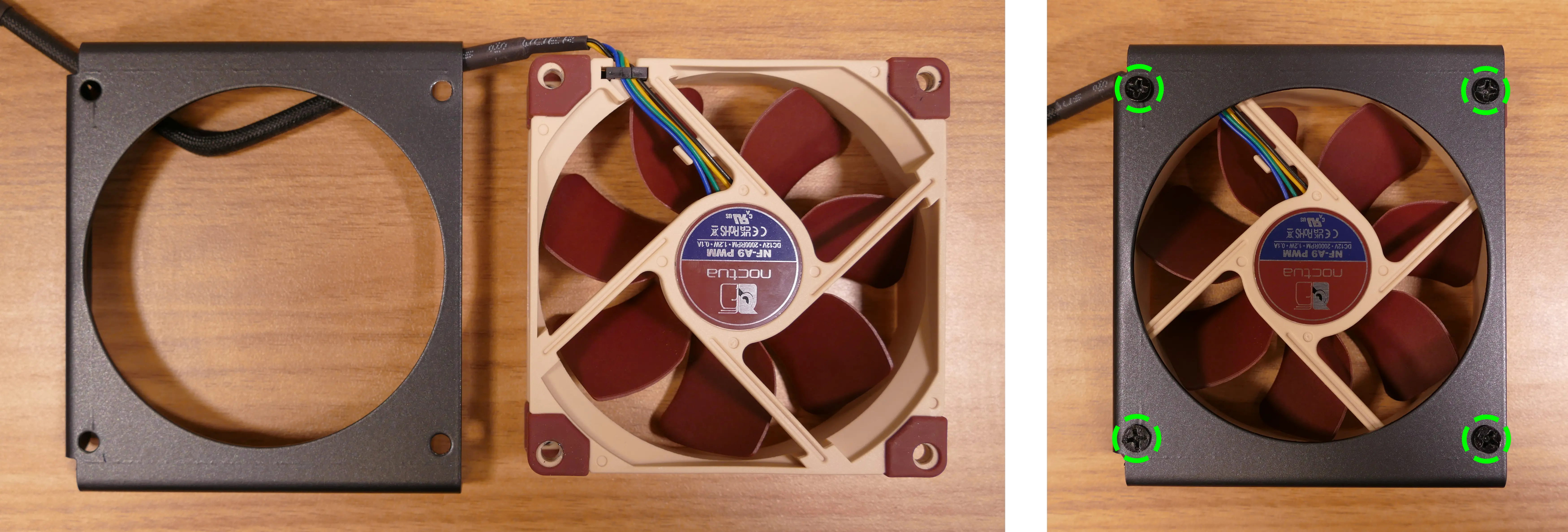
- Place the CPU duct fan and bracket into the CPU duct, with the thinnest side of the bracket (without the 90-degree flange) pointed into the duct.
- The spinning side of the fan should face the front of the chassis, while the stationary cover should face the back of the chassis.
- Replace the screws holding the fan bracket onto the CPU duct.
- The front and back brackets face in opposite directions from each other.
Steps to replace the preinstalled CPU duct fan (back):
- Remove the top case and the CPU duct.
- Remove the back fan bracket from the CPU duct by unscrewing the four screws (highlighted yellow below) and pulling it out of the CPU duct.

- Unscrew the four fan screws holding the fan onto the bracket.
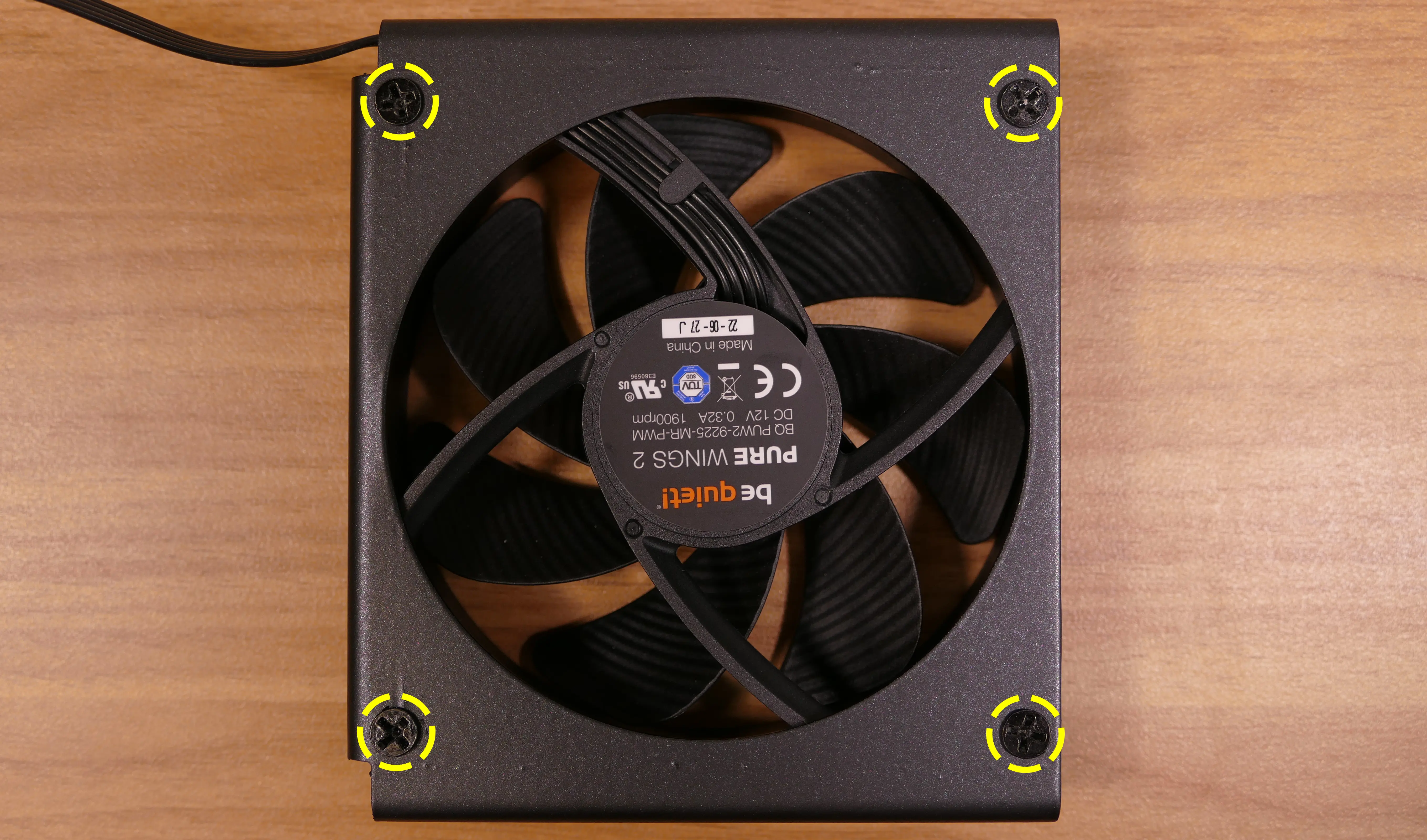
- When reinstalling the fan, the stationary cover should face the back of the chassis, and the wire should face the upper interior corner of the chassis (with the fan cover's logo upside-down). The thinnest side of the bracket (without the 90-degree flange) should face directly into the duct.
- The wire can be oriented in other directions if desired for cable management purposes, as long as the wire is able to reach the fan splitter board after the fan and CPU cooler heatsink are installed.
Installing the GPU:
nebula19 supports GPUs up to 278.175mm long. For optimal cooling and ease of installation, GPUs longer than 268.175mm are not recommended.
These instructions also apply to other PCI Express cards, such as add-in sound cards or networking cards.
- Tools required: Cross-head (Phillips) screwdriver
Steps to install the GPU:
- If not already installed, install the motherboard.
- If the motherboard is already installed and the system is assembled, then remove the top case and remove the side fan bracket.
- Unscrew the two screws holding the PCIe bracket onto the chassis, then remove the bracket.
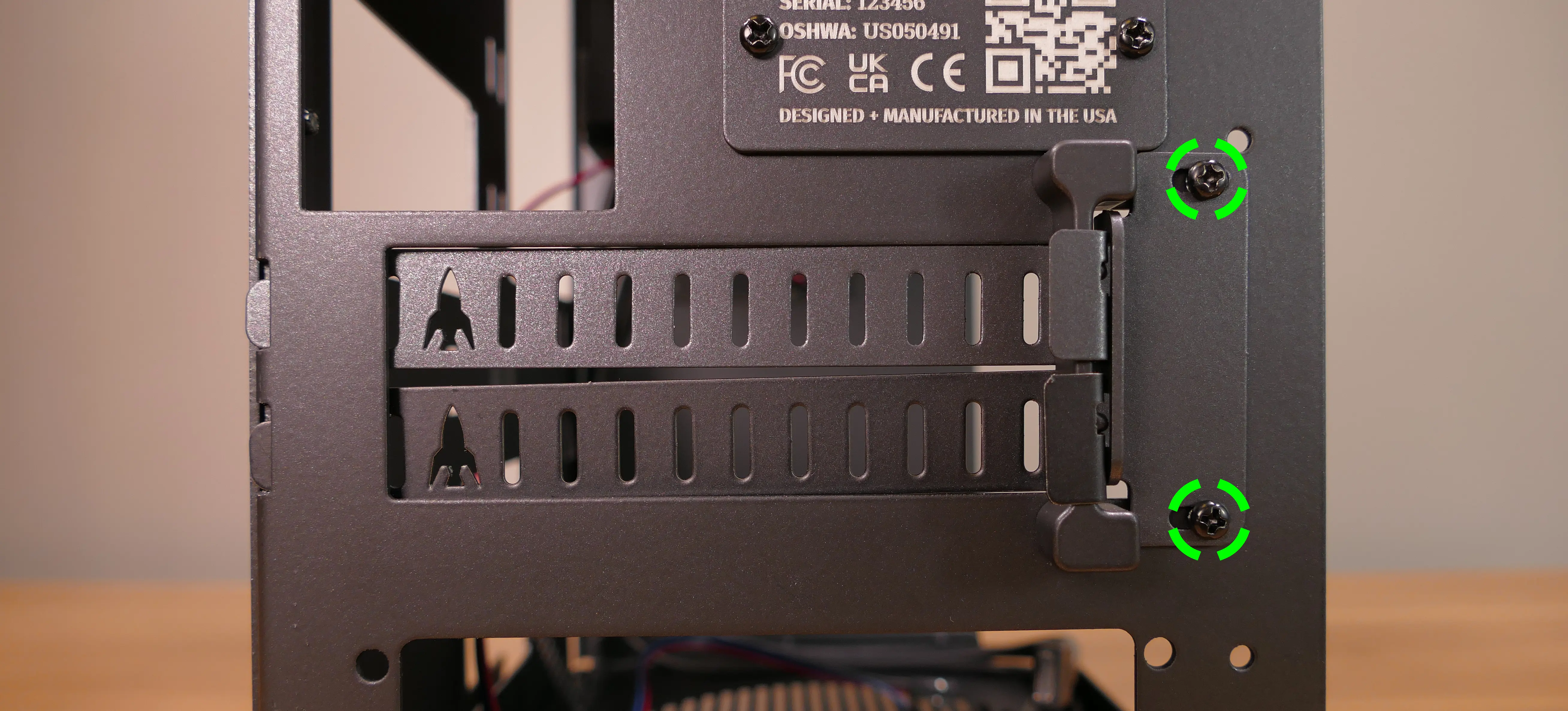
- Remove a PCIe slot cover for each slot the new GPU will take up.
- Additional slot covers may fall off after removing the PCIe brakcet; hold them up when replacing the bracket.
- Install the GPU into the motherboard.
- Replace the PCIe bracket, which will hold the end of the GPU in place.
Installing the SATA backplane:
nebula19 is designed to work with an optional SATA backplane to allow for easy hot-swapping of 2.5" storage drives. The SATA backplane can be seen below.

- Tools required: Cross-head (Phillips) screwdriver
Steps to install the SATA backplane:
- Remove the top case.
- The side fan bracket can also be removed for easier access to the SATA backplane screws and wiring.
- Unscrew and remove the 2.5" drive cage's cover.
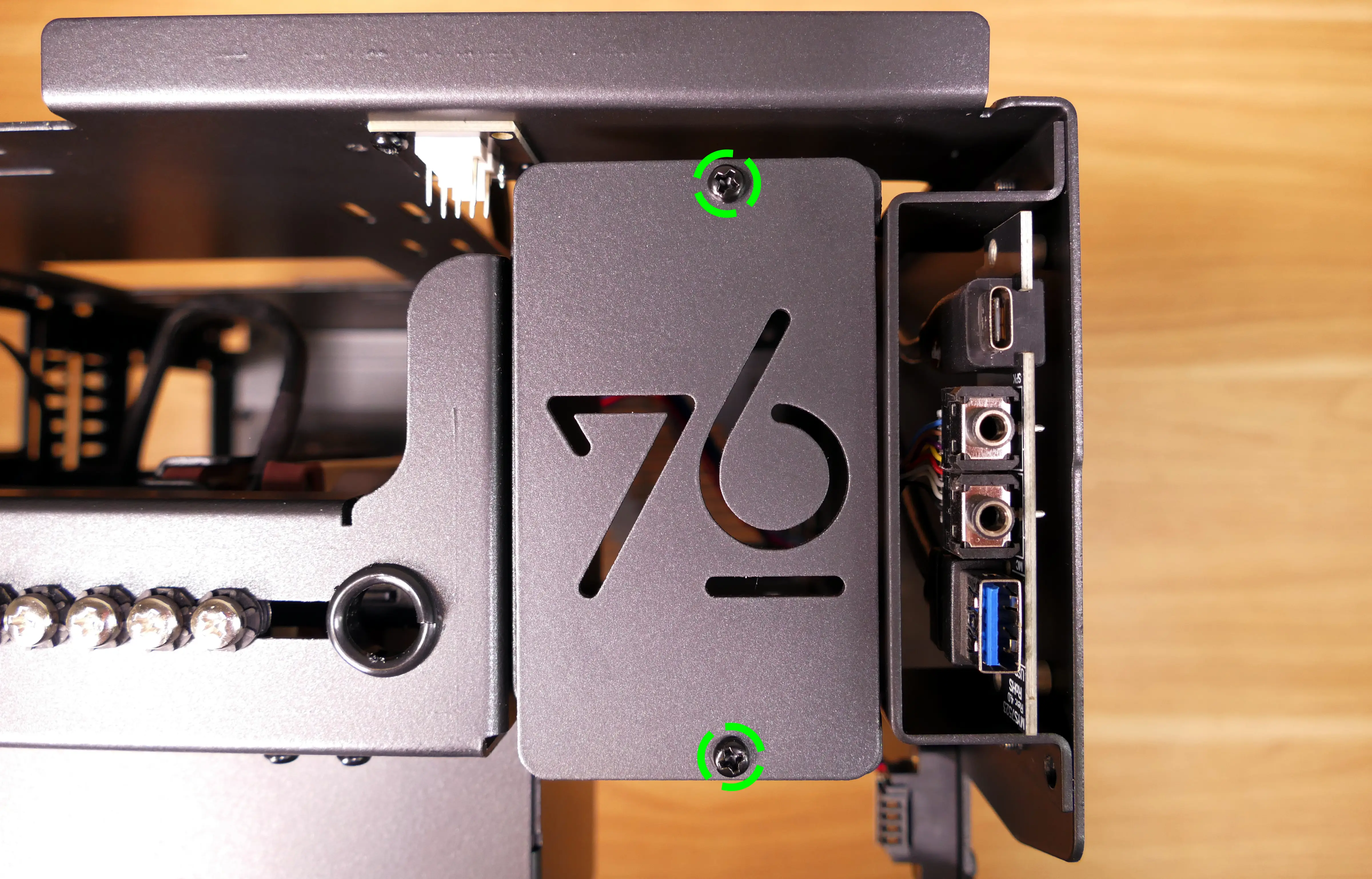
- If the SATA backplane's screw holes are covered by a translucent film, remove the film.
- Place the SATA backplane into the 2.5" drive cage, with the
SATA0label facing the front of the chassis.
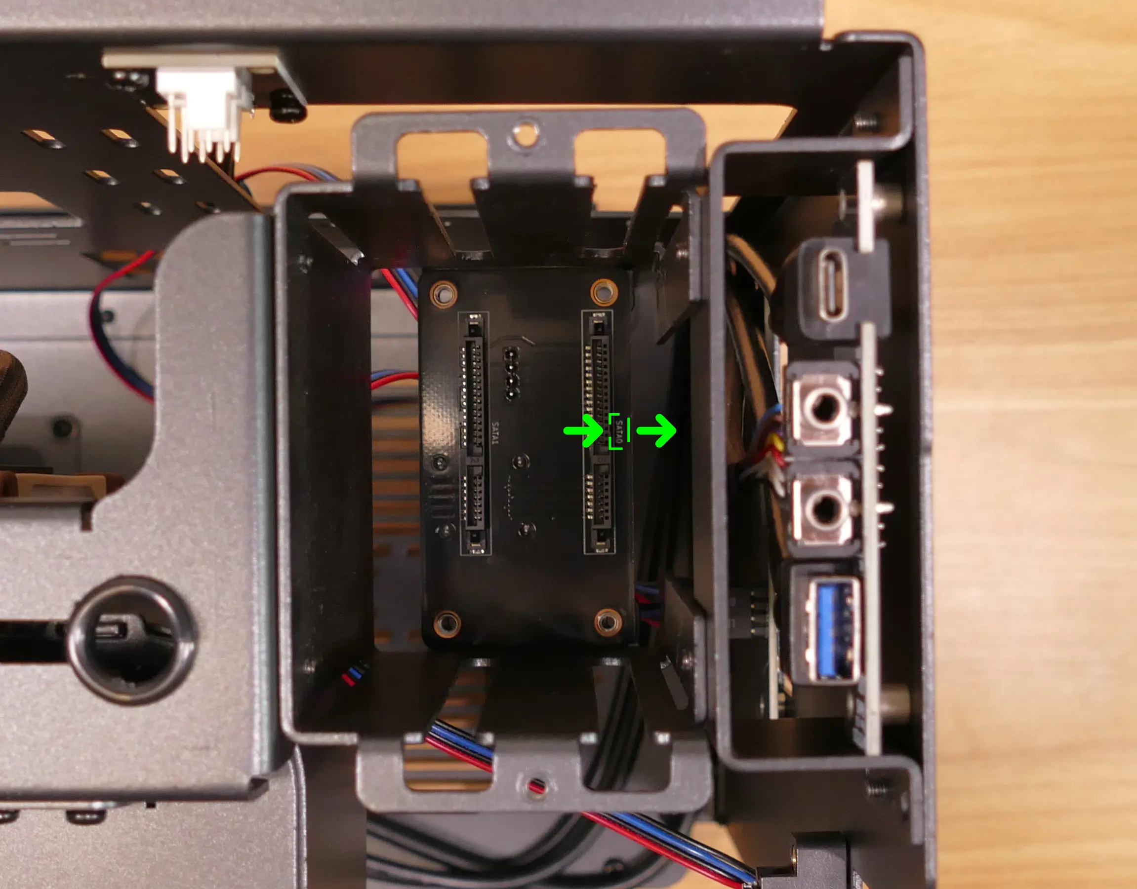
- Screw the backplane into the drive cage from the bottom using the four included M3 screws.
- Remember to turn the screwdriver counterclockwise instead of clockwise if you're looking at the screws from the top. Alternatively, the system can be placed on its side for easier access to the screw holes.
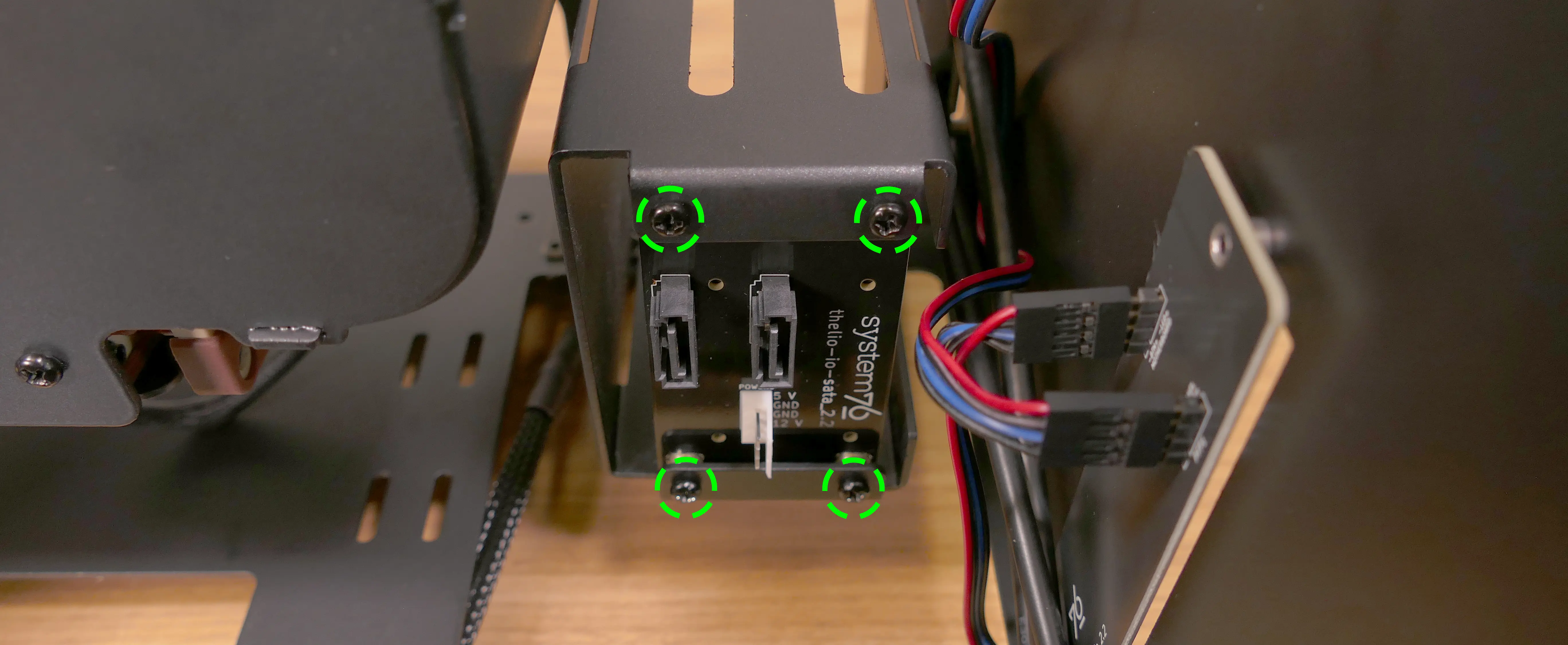
- Connect the white
POWER0header on the back of the SATA backplane to the power supply, and the blackDATA0andDATA1ports to two of the motherboard's SATA ports.- The
POWER0header uses a four-pin Berg connector, also known as a floppy drive power connector.
- The
- Install any 2.5" SATA drives and replace the drive cage cover, side fan bracket (if necessary), and top case.
Installing 2.5" drives:
The drive cage can hold two 2.5" drives. Drives of 7.5mm, 9mm, or 15mm are supported. Airflow will decrease below recommended levels with drives larger than 15mm.
- Tools required: Cross-head (Phillips) screwdriver
Steps to install 2.5" drives:
- Remove the top case.
- Unscrew and remove the 2.5" drive cage's cover.
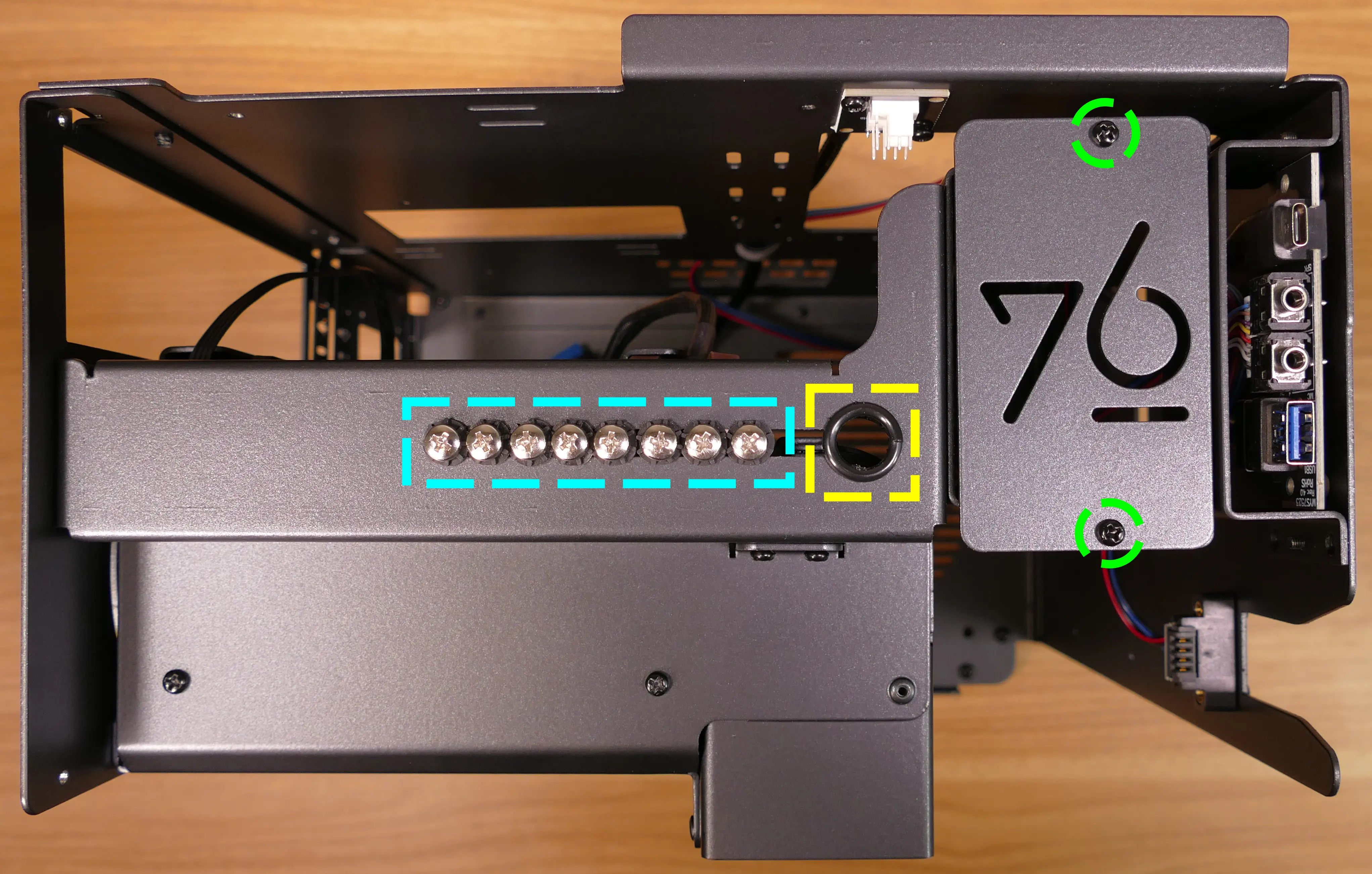
- Remove the plastic ring from the top crossbar and slide out four screws for each drive being installed.
- Insert two screws into each side of the 2.5" drive, then slide the drive into the drive cage, aligning the rubber mounts on the screws around the metal of the drive cage.
- The larger portion of the SATA connector (the power section) should be at the top, while the smaller portion (the data section) should be at the bottom.
- If the optional SATA backplane is not present, connect the SATA data and power cables from the bottom of the drive cage.
- A cutout in the chassis allows easy access to the bottom of the drive cage.
Installing the bottom case fan:
The case includes a 140mm Be Quiet! Silent Wings 4 BQ SIW4-14025-LF-PWM fan (not installed by default).
- Tools required: Cross-head (Phillips) screwdriver
Steps to replace the bottom case fan:
- Remove the top case and remove the side fan bracket.
- Remove the fan, dust filter, and fan screws from the 140mm fan box.

- Set the machine down on its side.
- Line the components up over the fan screw holes.
- The dust filter should have the shiny side facing the chassis.
- The fan should have the stationary cover facing upwards and the wire facing the front-interior corner of the machine.
- The wire can be passed through a cable management hole in the front-interior corner of the machine.
- Screw in the bottom fan from the bottom of the chassis.
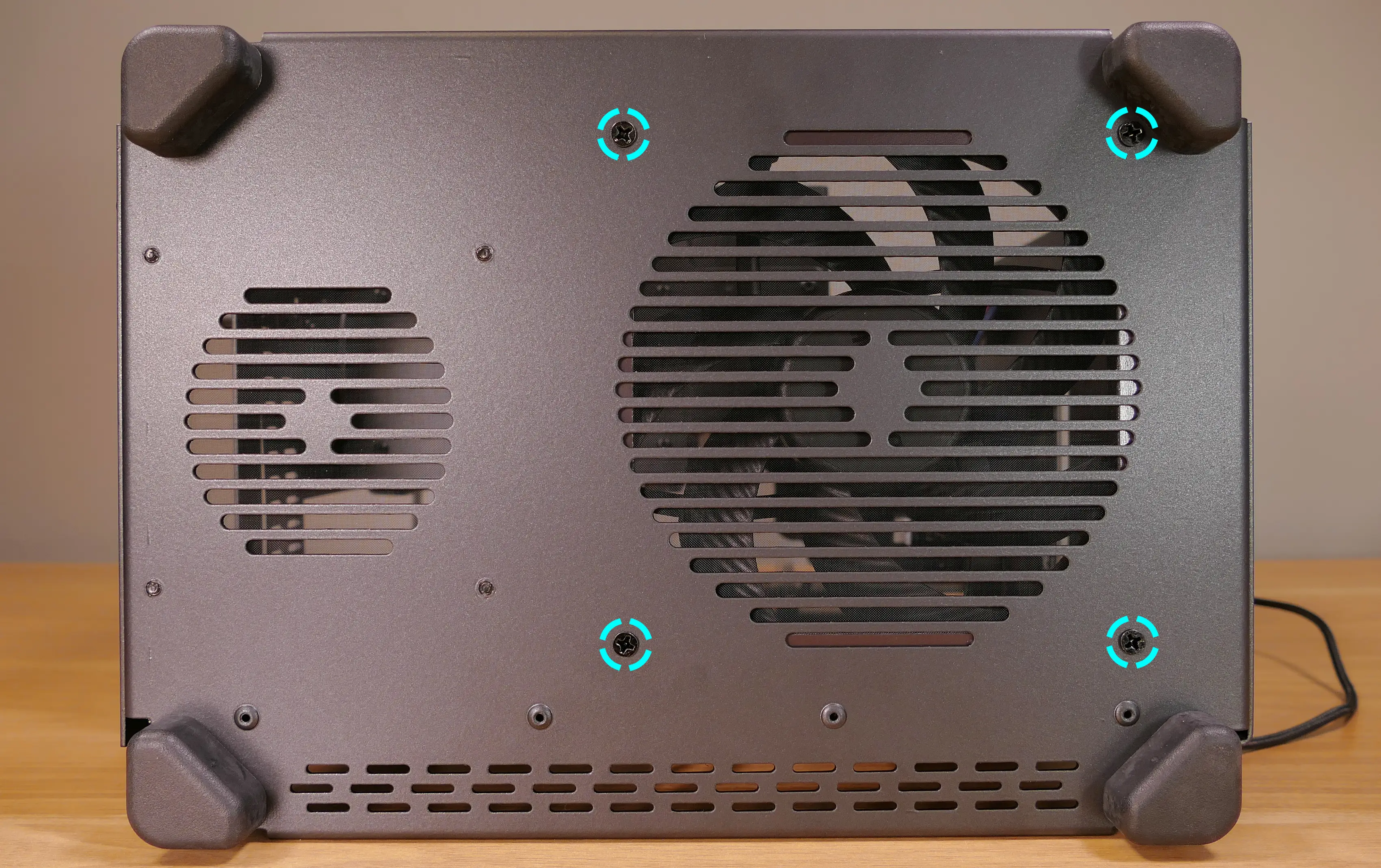
Installing side intake fan:
nebula19 supports one 120mm side intake fan mounted to the side fan bracket. A 120mm Be Quiet! Silent Wings 4 fan (BQ SIW4-12025-MF-PWM) is available as an optional add-on at the time of purchase.
Steps to install the side intake fan:
- Remove the top case and remove the side fan bracket.
- Unpack the fan, dust filter, and fan screws from the fan box.

- Place the dust filter and fan in the desired position along the side fan bracket.
- The shiny side of the dust filter should face the side fan bracket.
- The spinning side of the fan should face outward, while the stationary label should face inward.
- The fan wire should be oriented towards the fan splitter board on the side fan bracket.
- From the back, screw the fan screws through the side fan bracket and into the fan.
- Plug the side fan into one of the headers on the side fan bracket's fan splitter board. The nearby velcro strap can be used to hold the fan's cable.
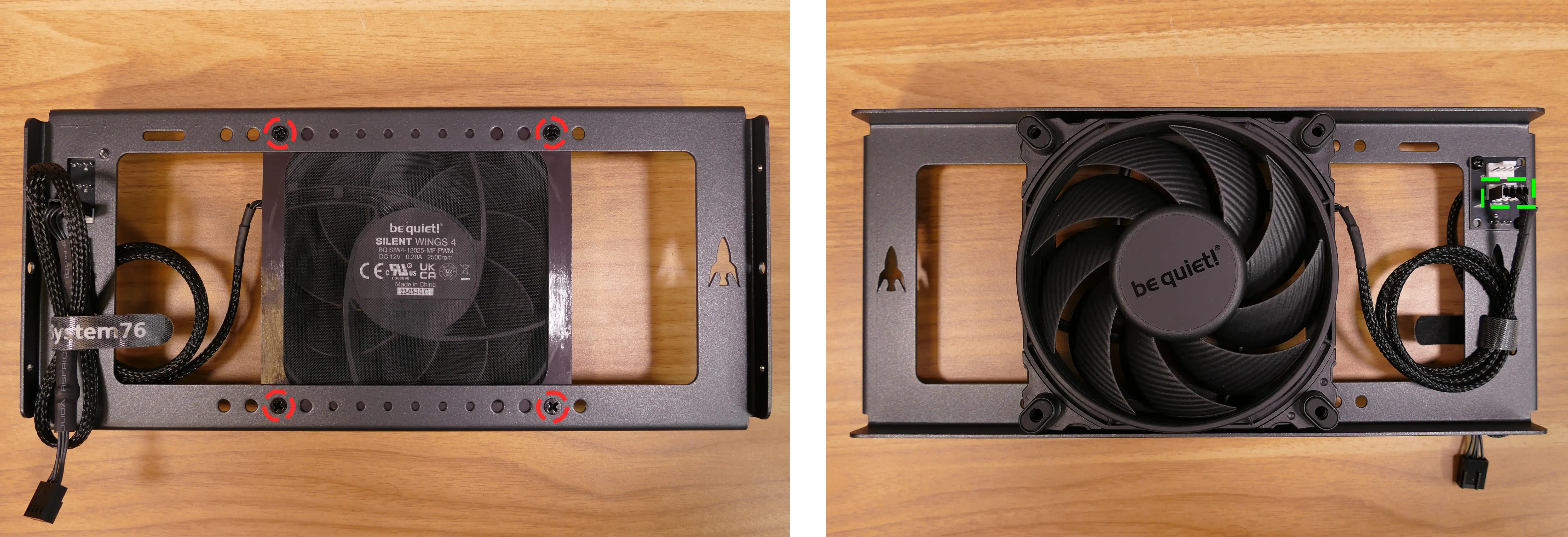
- Replace the side fan bracket and top case.
Installing the power supply:
The system supports standard SFX power supplies. nebula19 includes a dust filter installed over the power supply's fan vent.
- Tools required: Cross-head (Phillips) screwdriver
Steps to install the power supply:
- Remove the top case and remove the side fan bracket.
- Place the power supply into the chassis with the fan facing down.
- While holding the power supply against the back of the chassis, screw in the four power supply screws.
- Power supply screws are typically included with the power supply, and are not included with nebula19.
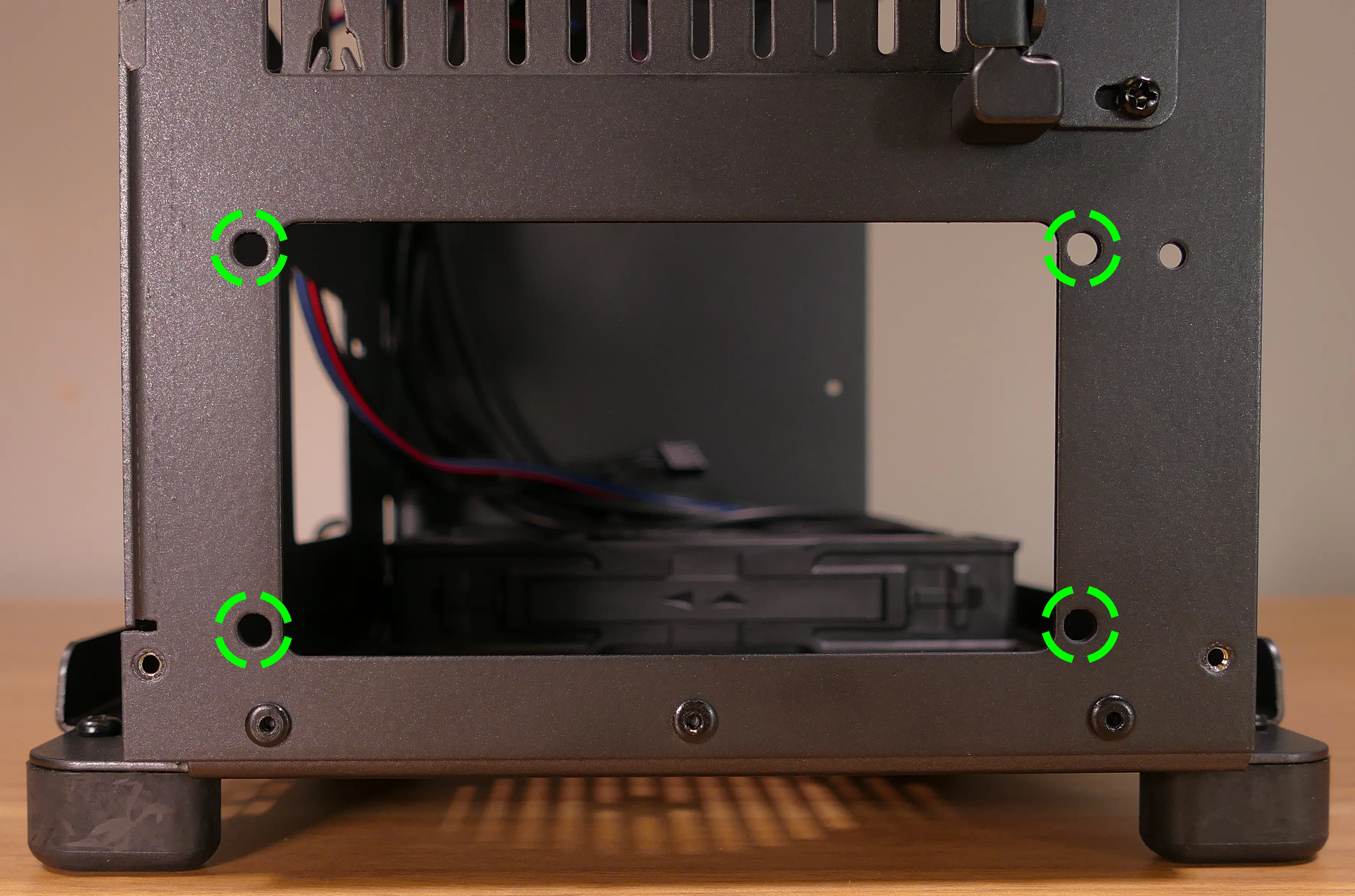
Steps to replace the power supply dust filter:
- Remove the top case and remove the power supply.
- Unscrew the four screws holding the dust filter onto the chassis.
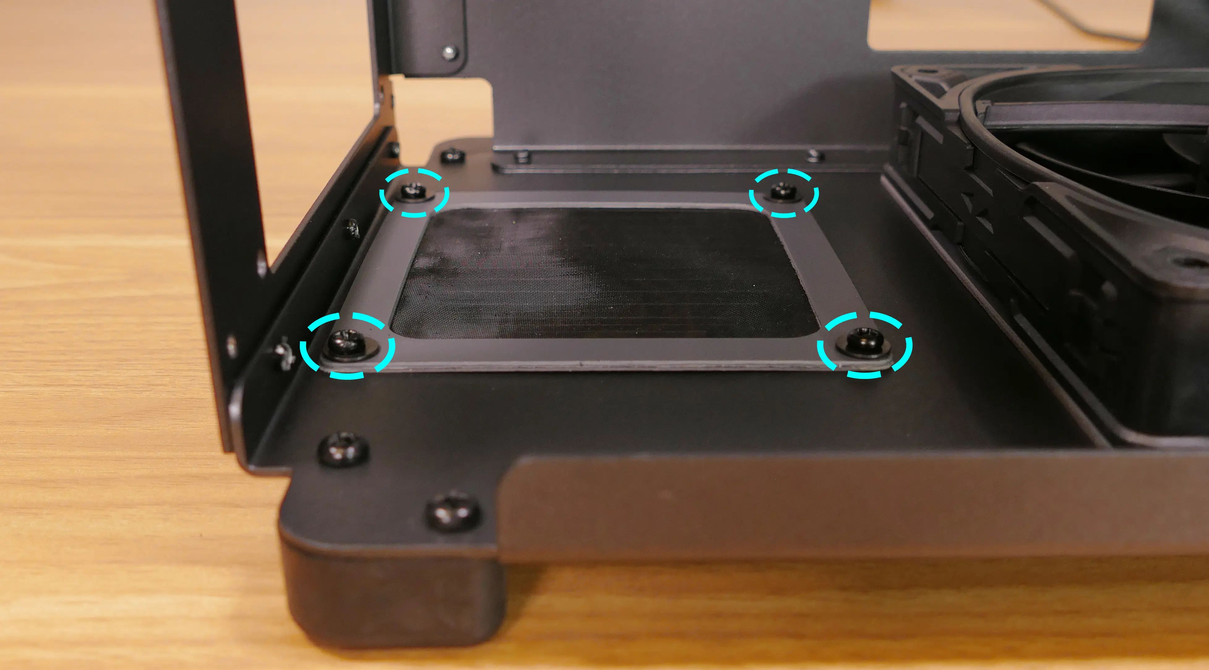
- Remove, clean, and replace the dust filter.
Wiring the front I/O and power button:
nebula19 comes standard with two front daughterboards:
- The
nebula-io_2.2power button controller. - The
MYS7523 Rev. 2.0front I/O board.
The Nebula Io board can be used to power the system on when the top case is removed.
Both daughterboards can be removed and replaced if necessary. The external power button attached to the top case can also be replaced.
- Tools required: Cross-head (Phillips) screwdriver
Steps to wire the front I/O and power button:
- Remove the top case.
- Refer to the below diagram for powering the machine on or removing and replacing either daughterboard:
- The front I/O board screws are highlighted in green.
- The power button controller board screws are highlighted in red.
- The internal power button is highlighted in cyan.
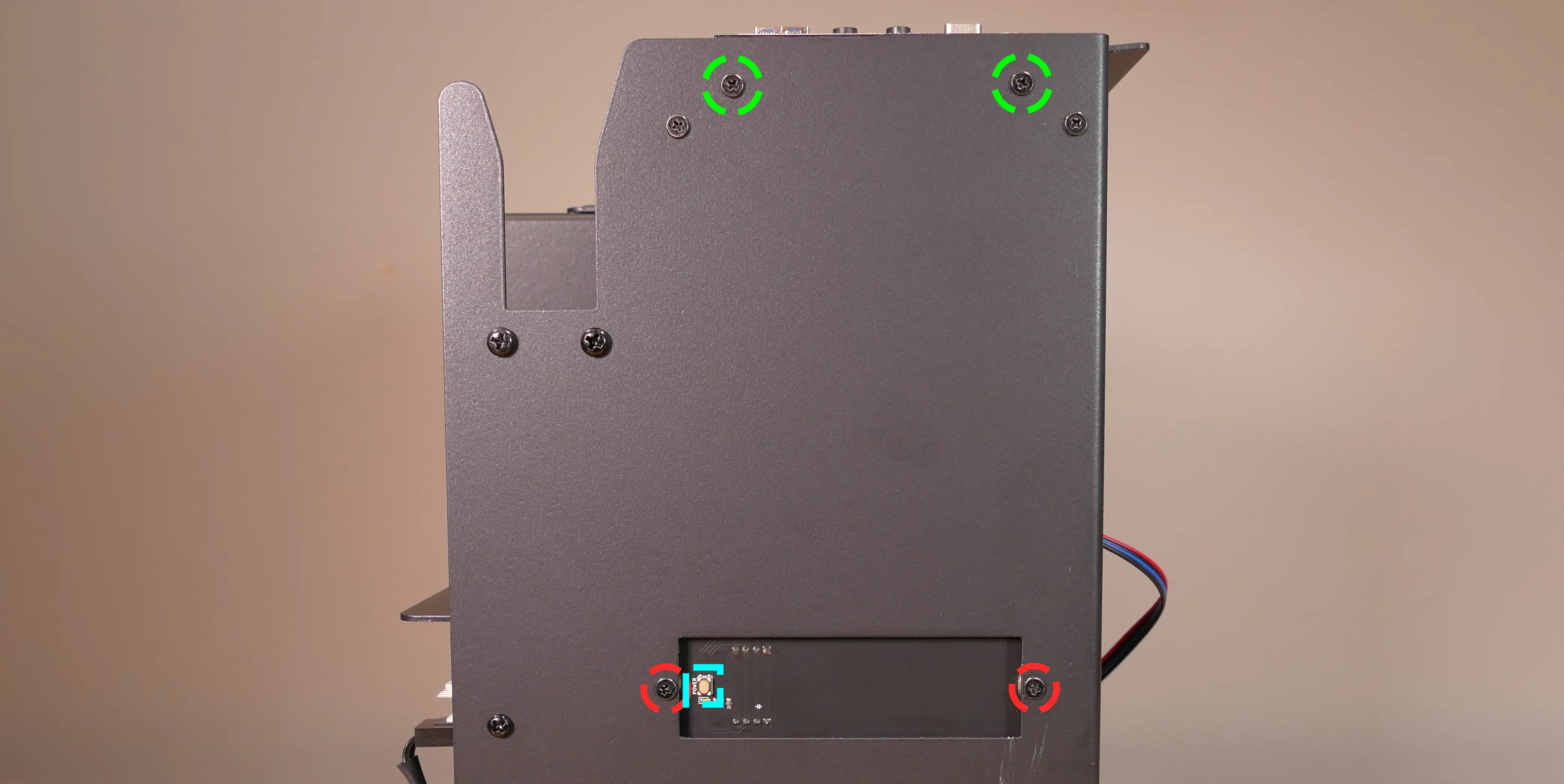
- Refer to the below diagram for wiring the front I/O and power button (the CPU duct and top crossbar have been removed for easier visibility):
- The USB Type-C port cable (highlighted green) connects to the motherboard's USB 3.1 header.
- The audio cable (highlighted yellow) connects to the motherboard's analog audio header.
- The USB Type-A port cable (highlighted cyan) connects to the motherboard's USB 3.0 header.
- The Nebula Io
PMB1header (highlighted red) connects to the motherboard's power button header.- The red wire should be on the right.
- The Nebula Io
PFP1header (highlighted pink) connects to the power button receptacle.- The red wire should be on the right.
- The power button receptacle header (highlighted orange) connects to the Nebula Io board.
- The red wire should be on the left.
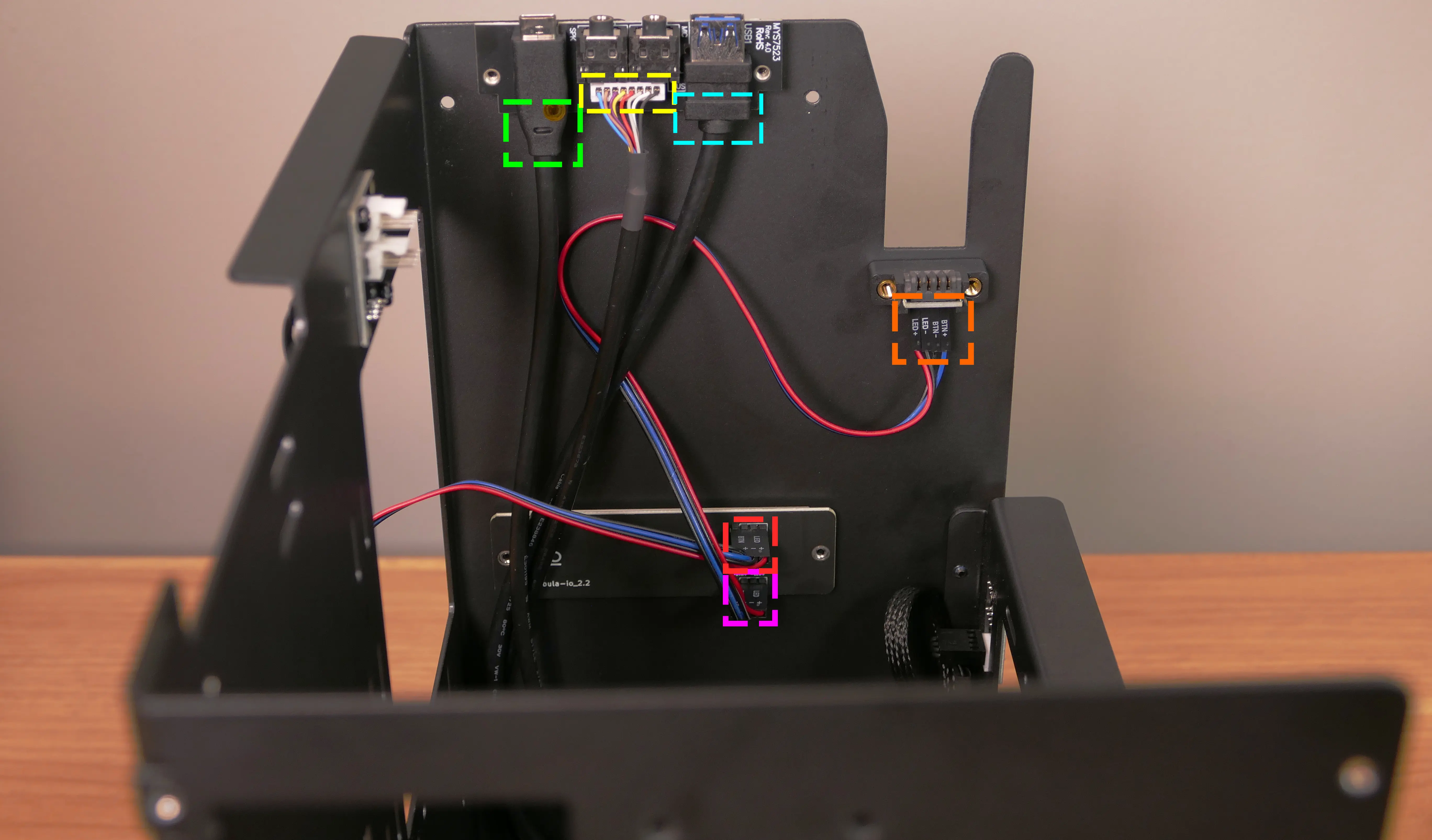
Steps to replace the power button:
- Remove the top case.
- Follow the instructions in the Replace the Thelio Power Button support article.
nebula40 (nebula40-3)
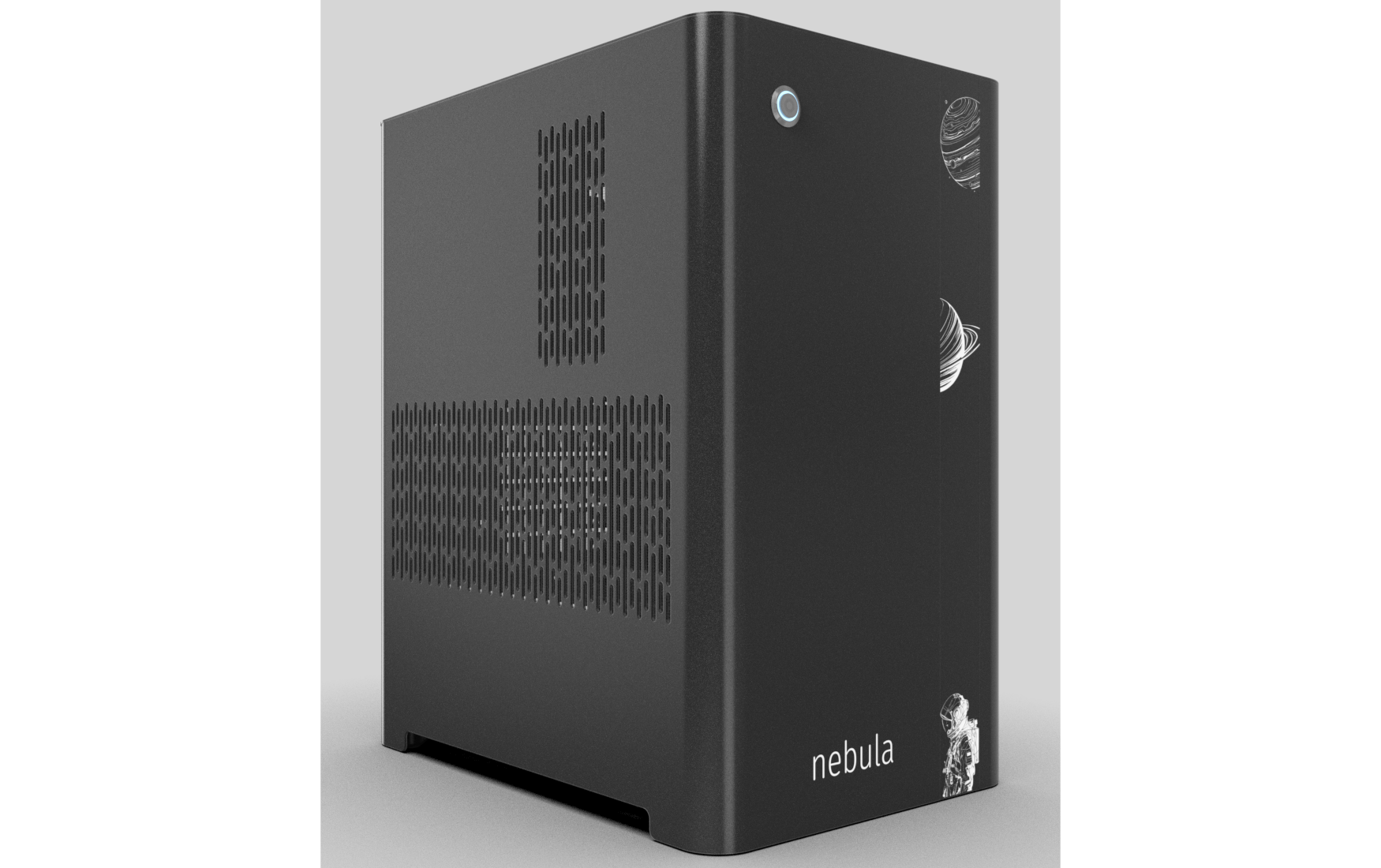
The System76 nebula40 is a desktop chassis (for DIY builds) with the following specifications:
- Dimensions
- Size: 43.75cm × 25.25cm × 37.06cm
- Volume: 40 liters
- Motherboard sizes
- ATX
- Mini-DTX
- DTX
- MicroATX
- Mini-ITX
- GPU compatibility
- Internal clearance: 357mm
- Recommended maximum length: 348mm
- Cooling capacity
- 1x 140mm bottom intake fan
- Be Quiet!
SIW4-14025-LF-PWM
- Be Quiet!
- CPU cooler
- Optional included cooler: Thermalright Phantom Spirit 120SE
- Includes 2x Thermalright
TL-C12B V2 PWM120mm fans
- Includes 2x Thermalright
- Max dimensions:
- Height (top to bottom of duct): 143mm
- Width (motherboard to side of duct): 170mm
- Length (front to back within duct): 176.3mm (126mm with fans)
- Optional included cooler: Thermalright Phantom Spirit 120SE
- 1x 120mm side intake fan (optional add-on)
- Be Quiet!
SIW4-12025-MF-PWM
- Be Quiet!
- 1x 140mm bottom intake fan
- Daughterboards
- Nebula Io power button controller board
- MYS7523 Rev. 2.0 front I/O board
- Thelio Io SATA 2.5" drive backplane (optional add-on)
nebula40 (External Overview)
Front/back overview:

Left/right side overview:

Top/bottom overview:

Front I/O (top to bottom, as pictured):
- USB 3.2 Gen 1 (Type-A)
- 3.5mm audio input (mic level)
- 3.5mm audio output (line level)
- USB 3.2 Gen 1 (Type-C)
Port capabilities depend on the motherboard installed in the system.
nebula40 (Parts & Assembly)
The nebula40 chassis is ready to be outfitted with standard personal computer components. If the system has already been built, ensure the system is powered off and all cables are unplugged from the motherboard, PCIe cards, power supply, and front I/O before opening the chassis.
The preinstalled velcro strips are left partially unwrapped to aid in removal. When building the system, you can optionally wrap the velcro up the rest of the way.
The nebula40-3 is the third iteration of the nebula40 (formerly nebula36) line of chassis.
- Replacing the front accent strip
- Removing the top case
- Removing the side fan bracket
- Removing the CPU duct
- Unpacking the included accessories
- Installing the motherboard
- Installing the CPU fans
- Installing the GPU
- Installing or replacing the SATA backplane
- Installing 2.5" drives
- Replacing the bottom case fan
- Installing side intake fans
- Installing the power supply
- Wiring the front I/O and power button
Replacing the front accent strip:
nebula40 includes a customizable accent panel on the front of the case, which can be swapped to change the case's look and feel. The instructions for swapping the accent are also available in video form.
- Tools required: None
Steps to replace the front accent strip:
- Place the nebula40 on the edge of the desk so the front side is hanging off of the desk.
- The nebula40 can alternatively be lifted or tilted so the front of the computer is hovering above the desk.
- Slide the accent strip down to unlock it.
- The accent can be gripped at the bottom edge.
- Pull the accent strip off of the case, starting with the bottom edge.
- Place the new accent strip onto the front of the case and slide it up to lock it into place.

Removing the top case:
The top case can be removed to access the internal components.
- Tools required: Cross-head (Phillips) screwdriver (optional)
Steps to remove the top case:
- Remove the four outer screws holding the top case onto the machine.

- Slide the top case up and off of the machine.
Removing the side fan bracket:
The side fan bracket provides a mounting point to help keep installed GPUs (or other PCI Express cards) in place while transporting the system. It can also be used to mount up to two extra intake fans (one, a BQ SIW4-12025-MF-PWM, is optional when purchasing the chassis; a second is not included.)

The fan splitter on the side fan bracket is intended for fans mounted on the side fan bracket, and should not be used for the CPU duct fans or the bottom intake fan.
- Tools required: Cross-head (Phillips) screwdriver
Steps to remove the side fan bracket:
- Follow the steps above to remove the top case.
- Unscrew the four screws holding the side fan bracket in place (two on the front of the case, two on the back.)

- Pull the side fan bracket out of the chassis.
Removing the CPU duct:
The CPU duct supports one or more of the CPU fans and guides airflow from the side of the case through the CPU radiator to the back exhaust vent. The nebula40 CPU duct is custom-designed to work with the Thermalright Phantom Spirit 120 CPU cooler, which is available as an optional add-on at the time of purchase.

- Tools required: Cross-head (Phillips) screwdriver
Steps to remove the CPU duct:
- Follow the steps above to remove the top case.
- Unscrew the two side screws holding the CPU duct onto the top crossbar.

- Unscrew the four back screws holding the CPU duct onto the chassis.
- Hold onto the duct while removing the final screw so it doesn't fall.

- Pull the CPU duct out of the chassis.
- When replacing the CPU duct, ensure all fan cables are plugged into one of the fan splitter boards in the top right of the chassis.
Unpacking the included accessories:
nebula40 includes the following components preinstalled:
- 1x
nebula_iopower button controller board - 1x
MYS7523top I/O board - 3x four-pin fan splitter boards
- 1x bottom case fan
- Be Quiet! Silent Wings 4 140mm (
BQ SIW4-14025-LF-PWM)
- Be Quiet! Silent Wings 4 140mm (
- 2x short loopable velcro straps
In addition, nebula40 ships with the following non-installed accessories:
- 1x Screw and velcro box
- 22x short loopable velcro straps
- 1x long System76-branded velcro strap
- 9x motherboard standoffs
- 9x M3 (motherboard) screws
- 4x fan screws
- 1x CPU cooler w/ 2 fans (optional)
- Thermalright Phantom Spirit 120 CPU cooler w/
TL-C12B V2fans
- Thermalright Phantom Spirit 120 CPU cooler w/
- 1x Side bracket fan (optional)
- Be Quiet! Silent Wings 4 120mm (
BQ SIW4-12025-MF-PWM)
- Be Quiet! Silent Wings 4 120mm (
Steps to unpack the included accessories:
- Follow the steps above to remove the top case, remove the side fan bracket, and remove the CPU duct.
- Cut the zip ties holding the accessory boxes in place.
- The image below highlights where the zip ties are joined.
- The zip ties are white in the image below. The zip ties on your unit may vary in color or size, depending on the accessories you ordered and the date of assembly.
- You can alternatively use a flathead screwdriver to release the zip tie joints without cutting the zip ties.
- Remove the accessory boxes from the chassis.
Installing the motherboard:
nebula40 supports the following standard motherboard sizes:
- ATX
- Mini-DTX
- DTX
- MicroATX
- Mini-ITX
Nine standoffs and motherboard screws are included.
- Tools required: Cross-head (Phillips) screwdriver
Steps to install the motherboard:
- If they are installed, remove the top case, remove the CPU duct and remove the side fan bracket.
- Locate the standoffs and M3 screws from the brown screw and velcro box.

-
Insert the standoffs into the appropriate holes for your motherboard size. The standoff screw holes are marked with shapes on the chassis, which correspond to the most common motherboard sizes:
- Mini-ITX and Mini-DTX: hexagon (4 standoffs)
- MicroATX: square (9 standoffs)
- ATX: triangle (9 standoffs)
The photo below also includes symbols for one additional motherboard size:
- DTX: star (6 standoffs)

- Install the motherboard's I/O shield onto the back of the chassis by pressing it into place from the inside.
- Place the motherboard into the chassis, aligning the motherboard's screw holes with the installed standoffs.
- Screw the motherboard into the standoffs using the M3 screws.
Installing the CPU fans:
nebula40 optionally ships with a Thermalright Phantom Spirit 120 CPU cooler, which includes two TL-C12B V2 fans. It's recommended to install one fan in the center of the CPU cooler's heatsink, and the other fan in the CPU shroud behind the cooler.
The heatsink-mounted fan must be installed after installing the heatsink onto your motherboard.
- Tools required: Cross-head (Phillips) screwdriver
Steps to install the heatsink-mounted CPU fan (middle):
- Install the motherboard.
- Remove the CPU cooler heatsink, one CPU cooler fan, and two metal mounting clips from the CPU cooler box.
- Install the CPU cooler onto the motherboard.
- The fan covers the CPU cooler's screw holes, so the CPU cooler must be installed prior to mounting the fan.
- Place the fan with the stationary cover facing up and orient it so the wire points toward the top left.
- Insert a metal mounting clip into the top and bottom of the fan.
- Insert the clips from below the top layer of the fan so the hooks come out the top.
- Slide the fan into the center of the heatsink and clip the mounting clips onto the top and bottom of the back half of the heatsink.
- The below photo shows the clips attached to the heatsink in a Thelio Mira, which uses the nebula40 chassis and CPU cooler.
- The fan's stationary cover should face the back of the chassis, and the fan's wire should point towards the fan splitter board near the upper-right corner of the motherboard.
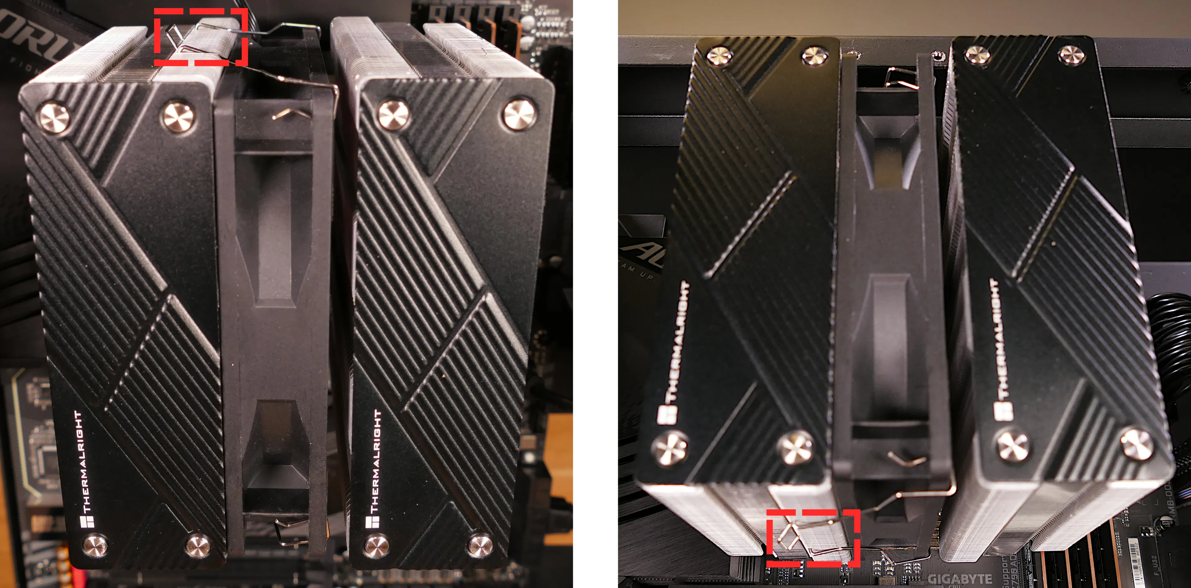
Steps to install the duct-mounted CPU fan (back):

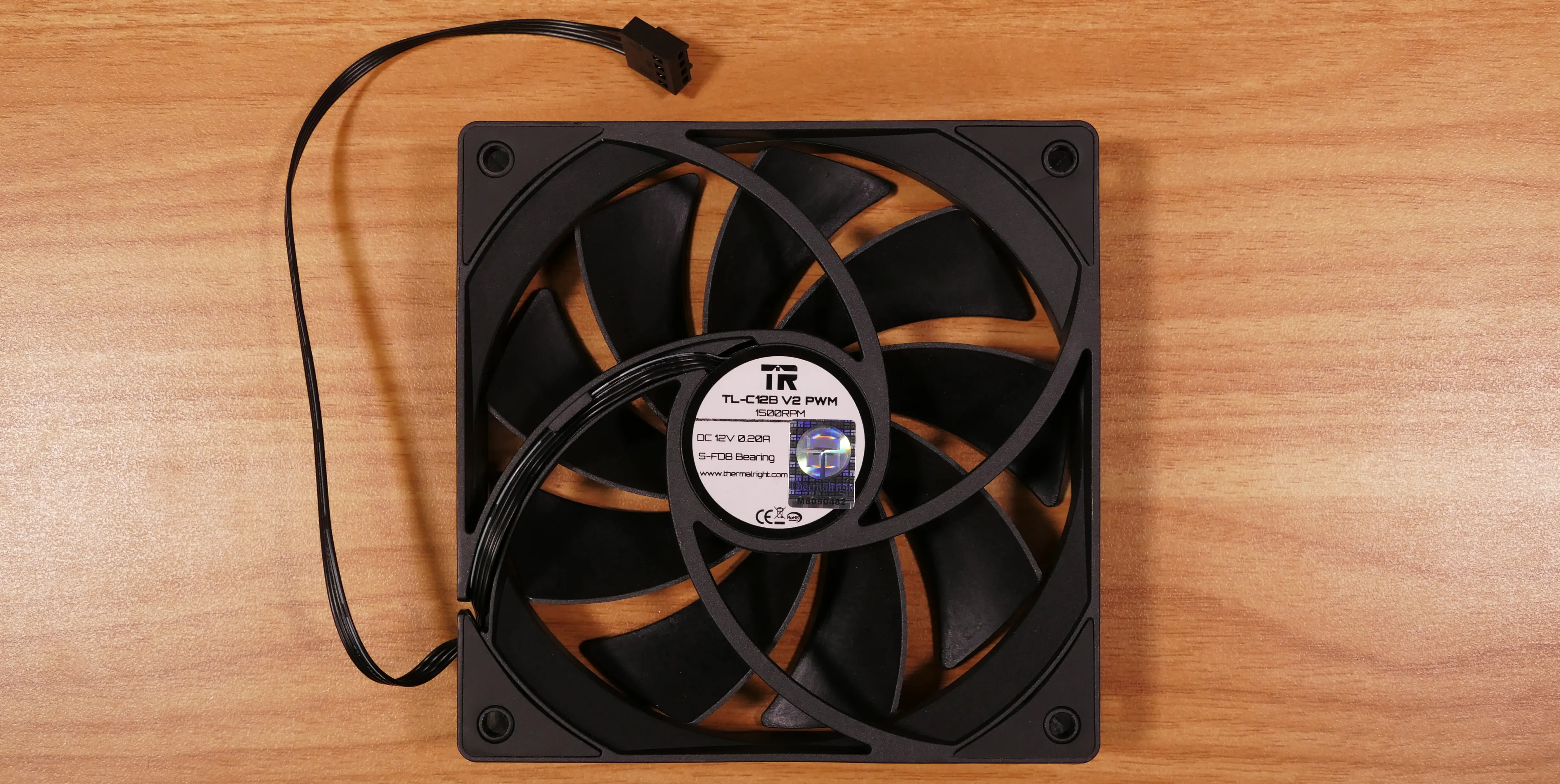
- Remove the fan screws from the brown screw and velcro box.

- Remove the back fan bracket from the CPU duct by unscrewing the four screws (highlighted yellow below) and pulling it out of the CPU duct.

- Place the spinning side of the fan down and the stationary cover up, then orient the fan so the wire points towards the top left.
- Place the fan bracket over the fan so the thinnest side (without the 90-degree flange) is on the right.
- Screw in the four fan screws.
- It may take some force to thread the fan screws into the fan's plastic frame.

- Place the CPU duct fan and bracket into the CPU duct, with the thinnest side of the bracket (without the 90-degree flange) pointed into the duct.
- The spinning side of the fan should face the front of the chassis, while the stationary cover should face the back of the chassis.
- Replace the screws holding the fan bracket onto the CPU duct.
Installing the GPU:
nebula40 supports GPUs up to 357mm long. For optimal cooling and ease of installation, GPUs longer than 348mm are not recommended.
These instructions also apply to other PCI Express cards, such as add-in sound cards or networking cards.
- Tools required: Cross-head (Phillips) screwdriver
Steps to install the GPU:
- If not already installed, install the motherboard.
- If the motherboard is already installed and the system is assembled, then remove the top case and remove the side fan bracket.
- If you're utilizing the top PCIe slot, you may also need to remove the CPU duct, depending on which set of screw holes it's mounted with.
- Unscrew the two screws holding the PCIe bracket onto the chassis, then remove the bracket.

- Remove a PCIe slot cover for each slot the new GPU will take up.
- Additional slot covers may fall off after removing the PCIe brakcet; set them back and hold them in place when replacing the bracket.
- Install the GPU into the motherboard.
- Replace the PCIe bracket, which will hold the end of the GPU in place.
Installing or replacing the SATA backplane:
nebula40 is designed to work with an optional SATA backplane to allow for easy hot-swapping of 2.5" storage drives. The SATA backplane can be seen below.

If you ordered the SATA backplane with your nebula40, it will come preinstalled in the chassis. The below instructions can be used to replace a damaged or defective backplane, or to install a backplane later if you didn't initially order it.
- Tools required: Cross-head (Phillips) screwdriver
Steps to install/replace the SATA backplane:
- Remove the top case.
- Unscrew and remove the 2.5" drive cage's cover.

- Unscrew and remove the 2.5" drive cage.
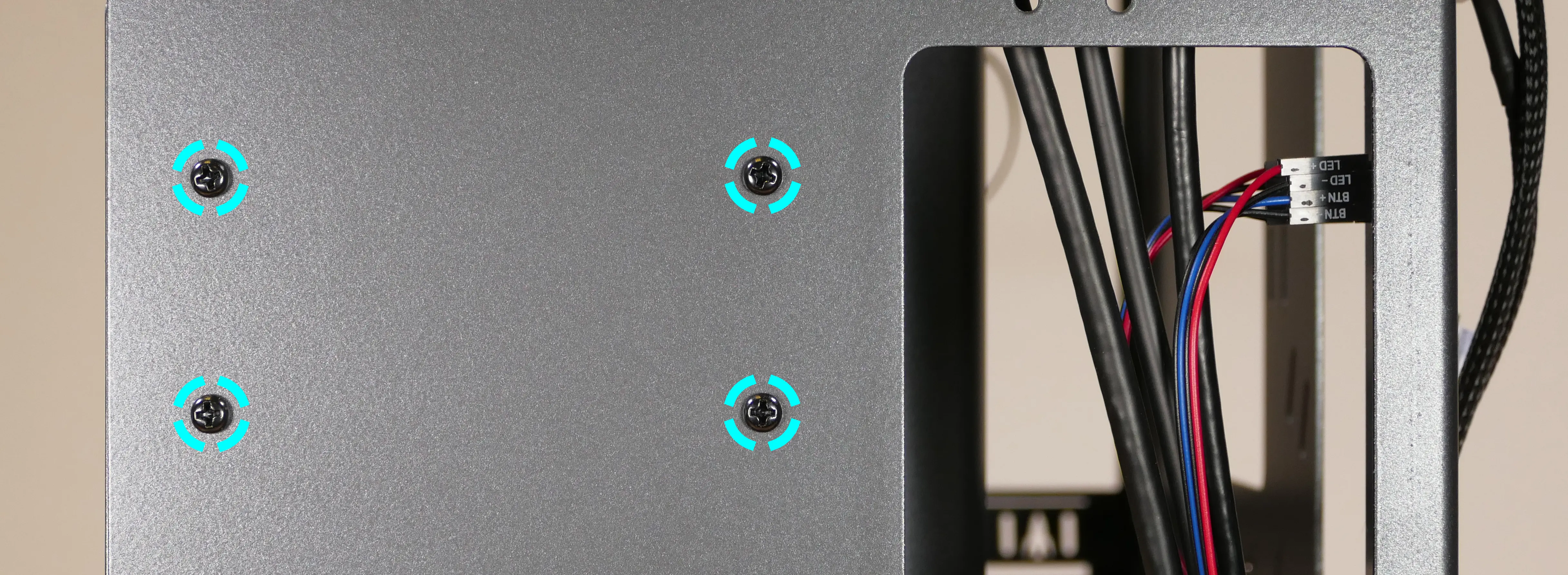
- If you're installing a new SATA backplane and its screw holes are covered by a translucent film, remove the film.
- If a SATA backplane is already installed, unscrew the four screws holding it into the drive cage from the outside.

- Remove the old SATA backplane (if necessary) and place the new SATA backplane into the drive cage.
- The backplane should be oriented so the power plug will be at the top of the board after installing the drive cage back into the chassis.
- Screw the backplane into the drive cage from the outside (as shown in the photo above).
- Screw the drive cage back onto the chassis.
- Connect the
POWER0header on the back of the SATA backplane to the power supply, and theDATA0andDATA1ports to two of the motherboard's SATA ports.- The
POWER0header uses a four-pin Berg connector, also known as a floppy drive power connector.
- The
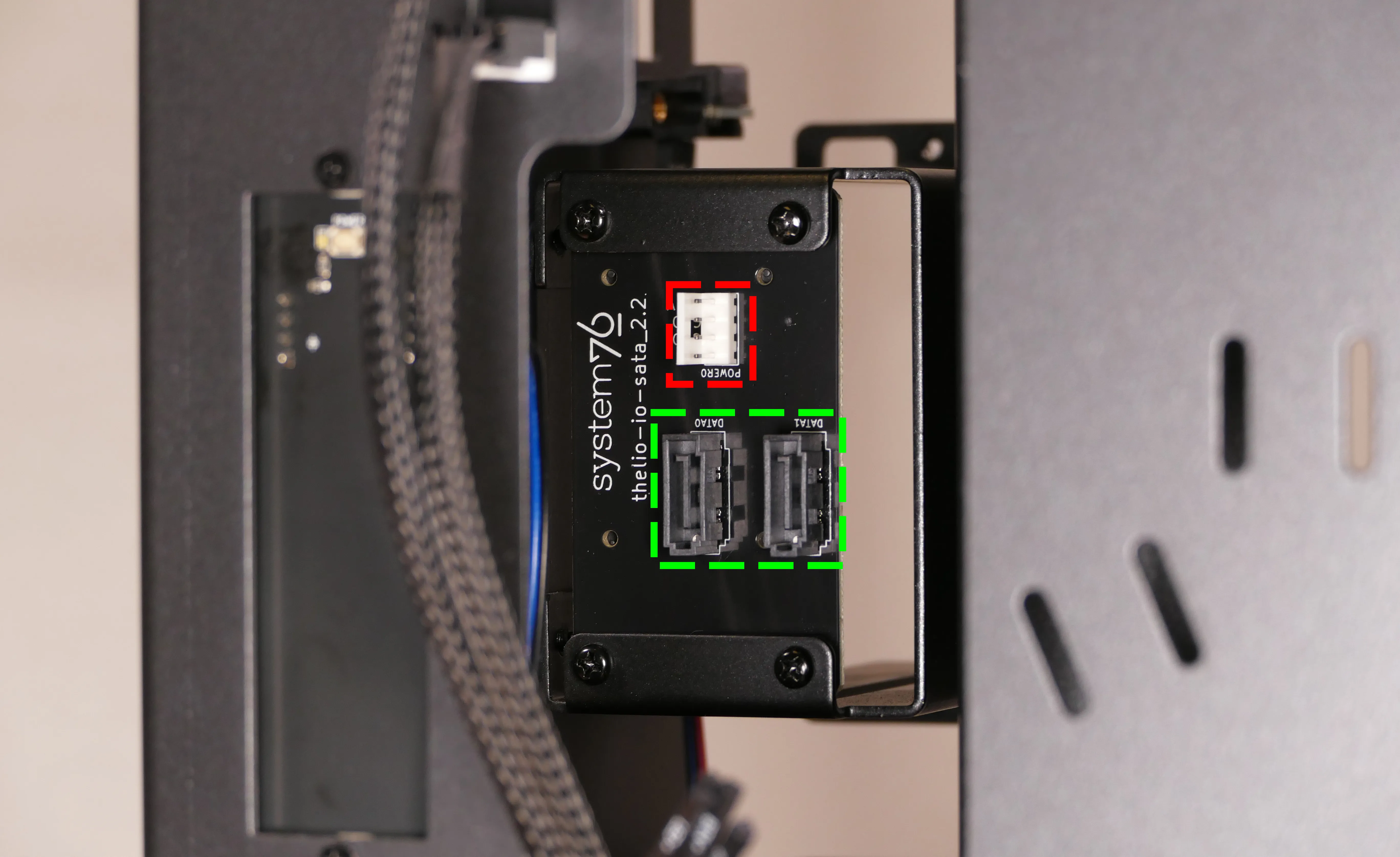
- Install any 2.5" SATA drives and replace the drive cage cover, side fan bracket (if necessary), and top case.
Installing 2.5" drives:
The drive cage can hold two 2.5" drives. Drives of 7.5mm, 9mm, or 15mm are supported. Airflow will decrease below recommended levels with drives larger than 15mm.
- Tools required: Cross-head (Phillips) screwdriver
Steps to install 2.5" drives:
- Remove the top case.
- Unscrew and remove the 2.5" drive cage's cover.

- Remove the plastic ring from the top crossbar and slide out four screws for each drive being installed.
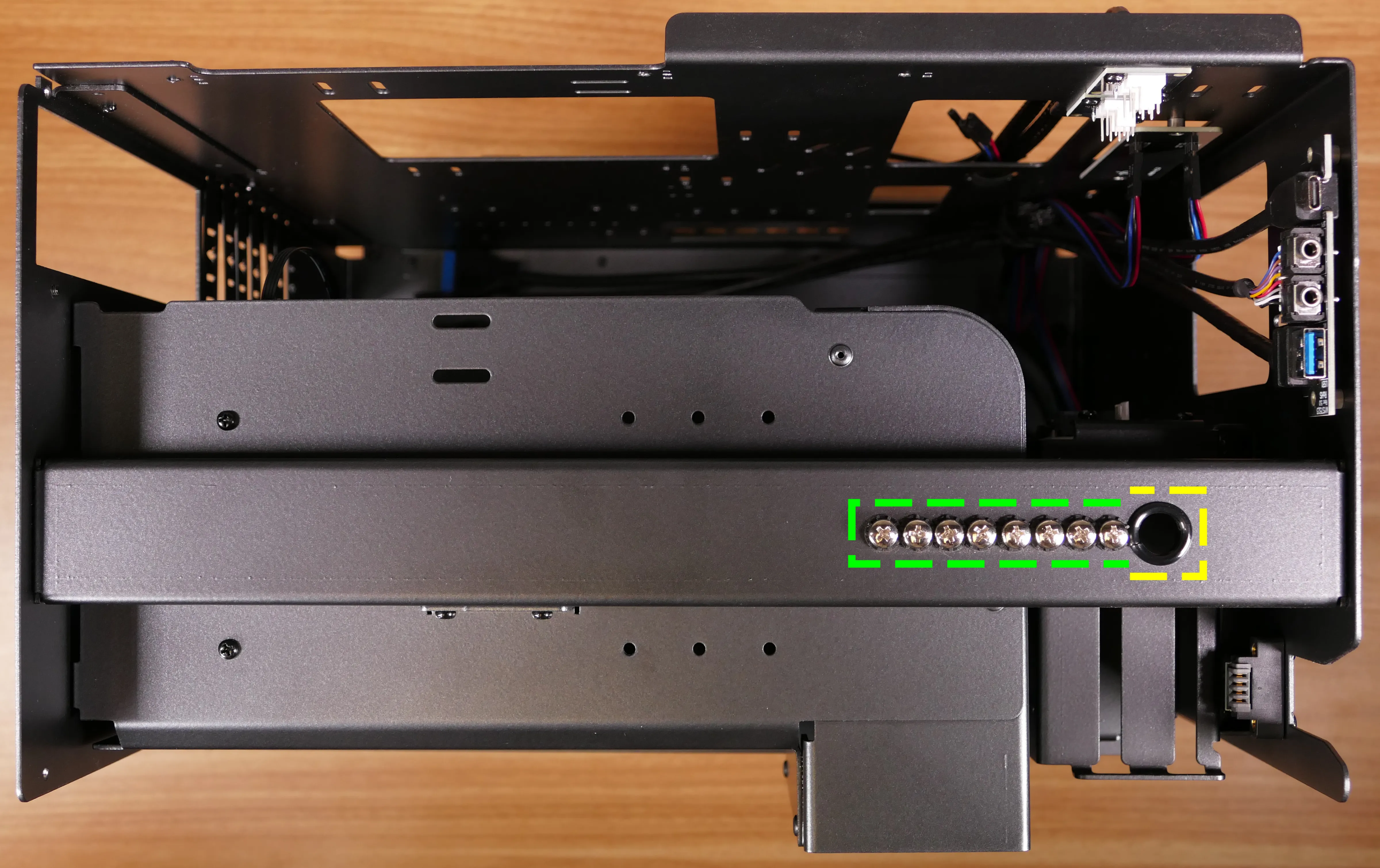
- Insert two screws into each side of the 2.5" drive, then slide the drive into the drive cage, aligning the rubber mounts on the screws around the metal of the drive cage.
- The larger portion of the SATA connector (the power section) should be at the top, while the smaller portion (the data section) should be at the bottom.
- If the optional SATA backplane is not present, connect the SATA data and power cables from the back of the drive cage.
- A cutout in the chassis allows easy access to the back of the drive cage.
Replacing the bottom case fan:
The 140mm bottom case fan (BQ SIW4-14025-LF-PWM) is preinstalled, but can be replaced if it becomes defective. The fan can also be removed to clean its dust filter.
- Tools required: Cross-head (Phillips) screwdriver
Steps to replace the bottom case fan:
- Remove the top case.
- The side fan bracket can optionally be removed to make working with the fan easier.
- If the system is already assembled, unplug the fan from the fan splitter board or motherboard.
- Set the machine down on its side and unscrew the four fan screws.

- When reinstalling the fan, place the dust filter between the fan and the chassis with the shiny side facing the chassis.
Installing side intake fans:
nebula40 supports up to two 120mm side intake fans mounted to the side fan bracket. One 120mm fan (BQ SIW4-12025-MF-PWM) is sold as an optional add-on at the time of purchase.
Steps to install the side intake fans:
- Remove the top case.
- Unpack the fan and rubber mounting pins from the fan box.
- The plastic rings included with the rubber mounting pins are not needed.
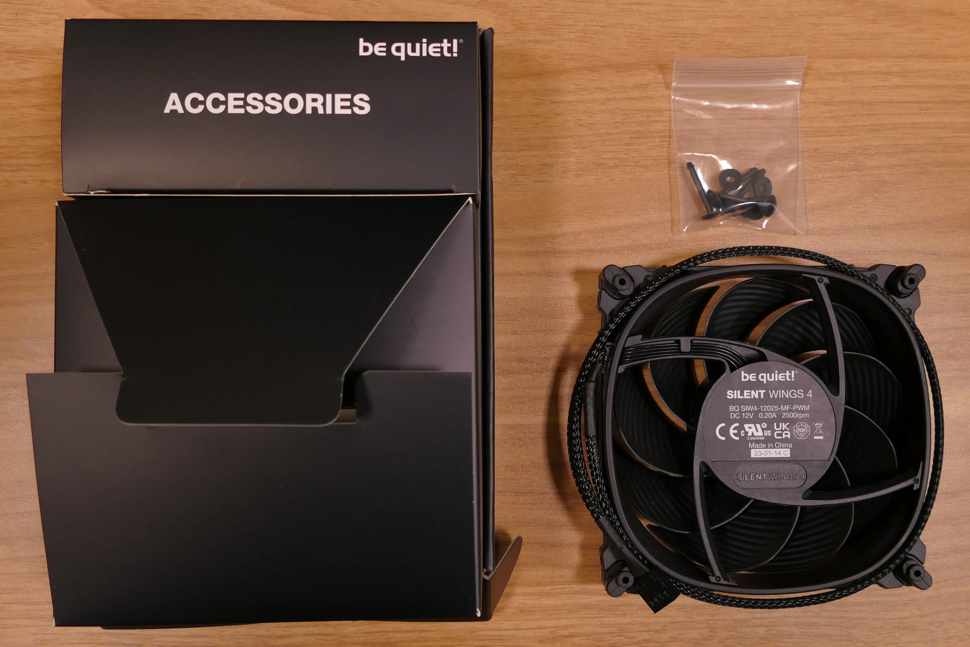
- Place the fan in the center of the side fan bracket.
- The spinning side of the fan should face outward, while the stationary label should face inward.
- The preinstalled pinholes on the fan will line up with the long holes in the side fan bracket (the fan must be held against the top of the bracket for the pinholes to align).
- From the back (inside of the machine), insert the rubber mounting pins through the pinholes at each corner of the fan.
- The side fan bracket can optionally be removed to make working with the rubber mounting pins easier.

- Plug the side fan into one of the headers on the side fan bracket's fan splitter board. The nearby velcro strap can be used to hold the fan's cable.
Installing the power supply:
The system supports standard ATX power supplies. nebula40 includes a dust filter installed over the power supply's fan vent.
- Tools required: Cross-head (Phillips) screwdriver
Steps to install the power supply:
- Remove the top case.
- The side fan bracket can optionally be removed to make working with the power supply easier.
- Place the power supply into the chassis with the fan facing down.
- Set the power supply on top of the rubber mounting post, then screw in the four power supply screws through the back of the chassis.
- Power supply screws are typically included with the power supply, and are not included with nebula40.
- You may need to hold the power supply up to the back of the chassis while screwing it in.

Steps to replace the power supply dust filter:
- Remove the top case and remove the power supply.
- Unscrew the screw securing the rubber mounting post from the bottom of the chassis, then remove the rubber mounting post.
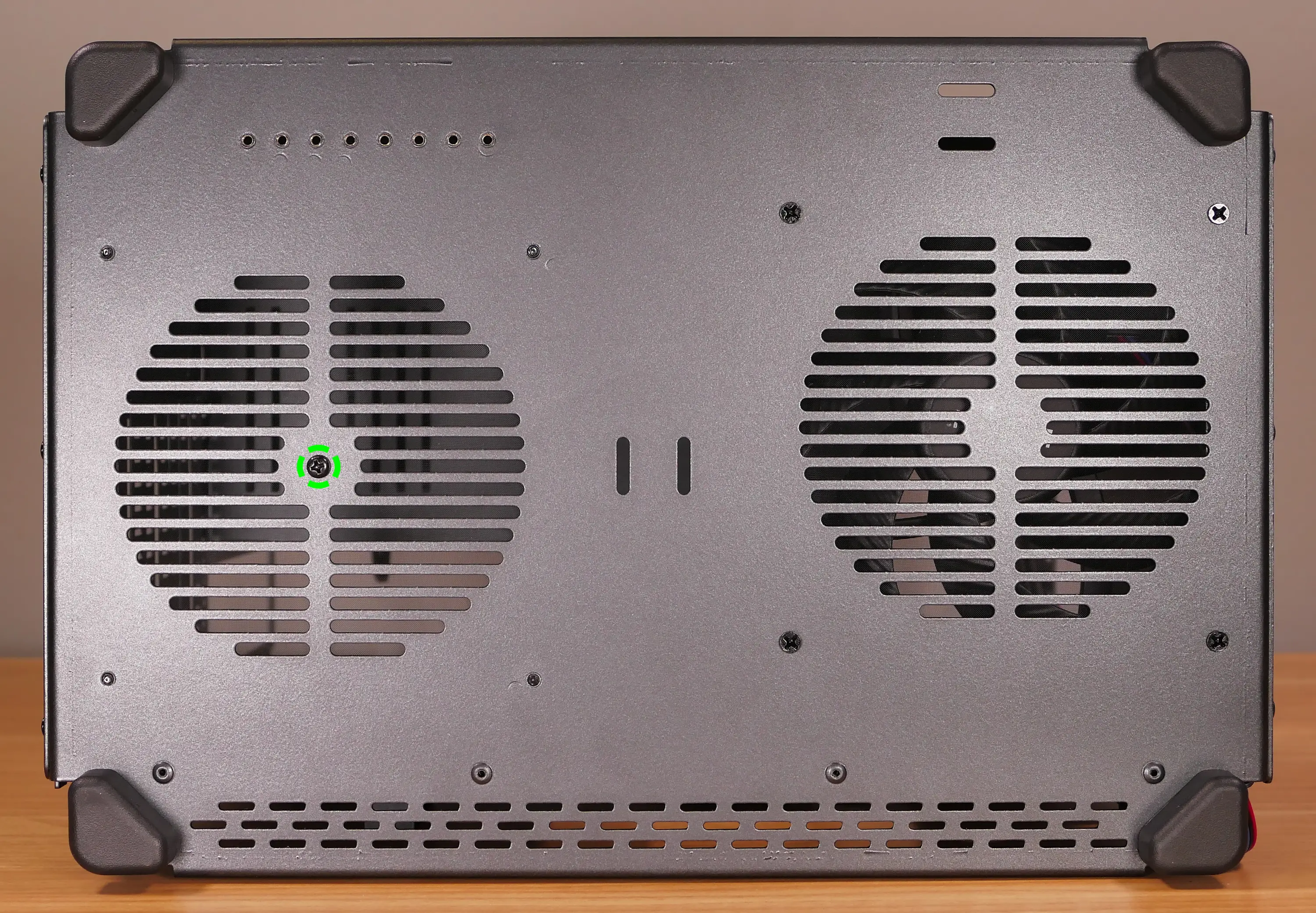
- Unscrew the four screws holding the dust filter onto the chassis.

- Remove, clean, and replace the dust filter.
Wiring the front I/O and power button:
nebula40 comes standard with two front daughterboards:
- The
nebula-io_2.2power button controller. - The
MYS7523 Rev. 2.0front I/O board.
The Nebula Io board can be used to power the system on when the top case is removed.
Both daughterboards can be removed and replaced if necessary. The external power button attached to the top case can also be replaced.
- Tools required: Cross-head (Phillips) screwdriver
Steps to wire the front I/O and power button:
- Remove the top case.
- Refer to the below diagram for powering the machine on or removing and replacing either daughterboard:
- The front I/O board screws are highlighted in green.
- The power button controller board screws are highlighted in red.
- The internal power button is highlighted in cyan.

- Refer to the below diagram for wiring the front I/O and power button (the CPU duct and top crossbar have been removed for easier visibility):
- The USB Type-C port cable (highlighted green) connects to the motherboard's USB 3.1 header.
- The audio cable (highlighted yellow) connects to the motherboard's analog audio header.
- The USB Type-A port cable (highlighted cyan) connects to the motherboard's USB 3.0 header.
- The Nebula Io
PMB1header (highlighted red) connects to the motherboard's power button header. - The Nebula Io
PFP1header (highlighted pink) connects to the power button receptacle. - The power button receptacle header (highlighted orange) connects to the Nebula Io board.

Steps to replace the power button:
- Remove the top case.
- Follow the instructions in the Replace the Thelio Power Button support article.
nebula49 (nebula49-1)
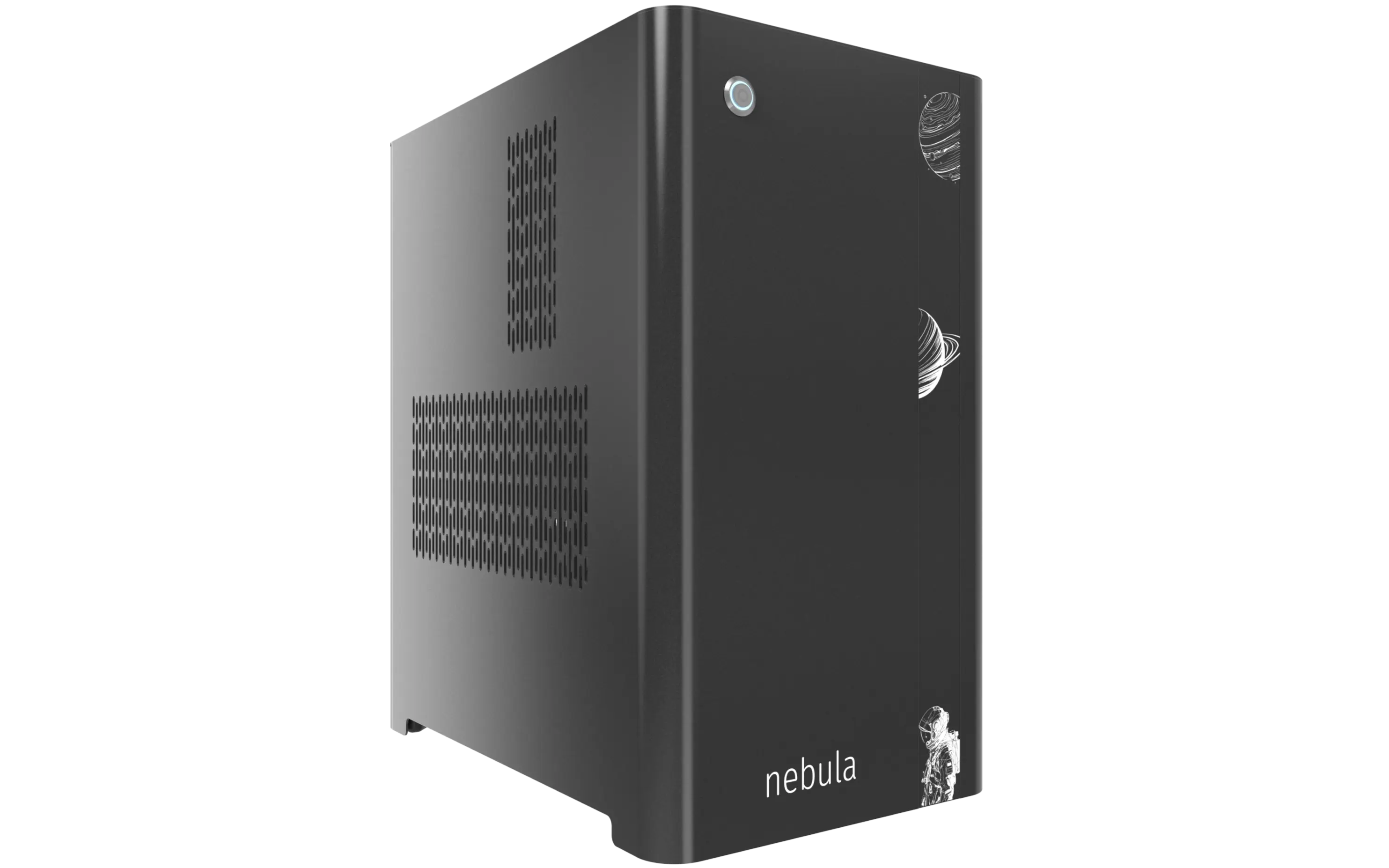
The System76 nebula49 is a desktop chassis (for DIY builds) with the following specifications:
- Dimensions
- Size: 46.2cm × 26.2cm × 40.8cm
- Volume: 49 litres
- Motherboard sizes
- Extended ATX (up to 10.7")
- ATX
- Mini-DTX
- DTX
- Mini-ITX
- GPU compatibility
- Internal clearance: 396.50mm
- Recommended maximum length: 386.50mm
- Cooling capacity
- 2x 120mm CPU fans
- Rear exhaust fan: Be Quiet!
SIW4-12025-MF-PWM - CPU cooler:
- Optional included cooler: Noctua
NH-U12S- Includes 1x Noctua
NF-F12 PWMfan
- Includes 1x Noctua
- Max dimensions:
- Height (top to bottom of duct): 142mm
- Width (motherboard to side of duct): 163mm
- Length (front to back within duct): 258mm (215mm with fans)
- Optional included cooler: Noctua
- Rear exhaust fan: Be Quiet!
- 1x 140mm bottom intake fan: Be Quiet!
SIW4-14025-HF-PWM - 2x 120mm side intake fans
- Optional add-on: Be Quiet!
SIW4-12025-MF-PWM
- Optional add-on: Be Quiet!
- 2x 120mm CPU fans
- Daughterboards
- Nebula Io power button controller board
- MYS7523 Rev. 2.0 front I/O board
- Thelio Io SATA 2.5" drive backplane (optional add-on)
nebula49 (External Overview)
Front/back overview:

Left/right side overview:

Top/bottom overview:

nebula49 (Parts & Assembly)
The nebula49 chassis is ready to be outfitted with standard personal computer components. If the system has already been built, ensure the system is powered off and all cables are unplugged from the motherboard, PCIe cards, power supply, and front I/O before opening the chassis.
The preinstalled velcro strips are left partially unwrapped to aid in removal. When building the system, you can optionally wrap the velcro up the rest of the way.
- Replacing the front accent strip
- Removing the top case
- Removing the side fan bracket
- Removing the CPU duct
- Unpacking the included accessories
- Installing the motherboard
- Installing the CPU duct fans
- Installing the GPU
- Installing the SATA backplane
- Installing 2.5" drives
- Replacing the bottom case fan
- Installing side intake fans
- Installing the power supply
- Wiring the front I/O and power button
Replacing the front accent strip:
nebula49 includes a customizable accent panel on the front of the case, which can be swapped to change the case's look and feel. The instructions for swapping the accent are also available in video form.
- Tools required: None
Steps to replace the front accent strip:
- Place the nebula49 on the edge of the desk so the front side is hanging off of the desk.
- The nebula49 can alternatively be lifted or tilted so the front of the computer is hovering above the desk.
- Slide the accent strip down to unlock it.
- The accent can be gripped at the bottom edge.
- Pull the accent strip off of the case, starting with the bottom edge.
- Place the new accent strip onto the front of the case and slide it up to lock it into place.

Removing the top case:
The top case can be removed to access the internal components.
- Tools required: Cross-head (Phillips) screwdriver (optional)
Steps to remove the top case:
- Remove the four outer screws holding the top case onto the machine.

- Slide the top case up and off of the machine.
Removing the side fan bracket:
The side fan bracket provides a mounting point to help keep installed GPUs (or other PCI Express cards) in place while transporting the system. It can also be used to mount up to two extra intake fans (two BQ SIW4-12025-MF-PWM fans are optional when purchasing the chassis.)

The fan splitter on the side fan bracket is intended for fans mounted on the side fan bracket, and should not be used for the CPU duct fans or the bottom intake fan.
- Tools required: Cross-head (Phillips) screwdriver
Steps to remove the side fan bracket:
- Follow the steps above to remove the top case.
- Unscrew the four screws holding the side fan bracket in place (two on the front of the case, two on the back.)

- Pull the side fan bracket out of the chassis.
Removing the CPU duct:
The CPU duct supports one or more of the CPU fans and guides airflow from the side of the case through the CPU radiator to the back exhaust vent. The CPU duct is custom-designed to work with the Noctua NH-U12S CPU cooler that's included with nebula49.

- Tools required: Cross-head (Phillips) screwdriver
Steps to remove the CPU duct:
- Follow the steps above to remove the top case.
- Unscrew the two side screws holding the CPU duct onto the top crossbar.

- Unscrew the four back screws holding the CPU duct onto the chassis.
- Hold onto the duct while removing the final screw so it doesn't fall.

- Pull the CPU duct out of the chassis.
- When replacing the CPU duct, ensure all fan cables are plugged into one of the fan splitter boards in the top right of the chassis.
Unpacking the included accessories:
nebula49 includes the following components preinstalled:
- 1x
nebula_iopower button controller board - 1x
MYS7523top I/O board - 3x Four-pin fan splitter boards
- 1x Back CPU duct fan
- Be Quiet! Silent Wings 4 120mm (
BQ SIW4-12025-MF-PWM)
- Be Quiet! Silent Wings 4 120mm (
- 1x Bottom case fan
- Be Quiet! Silent Wings 4 140mm (
BQ SIW4-14025-HF-PWM)
- Be Quiet! Silent Wings 4 140mm (
- 4x Short velcro straps
- 2x on the side of the chassis
- 1x on the bottom of the chassis
- 1x on the side fan bracket
In addition, nebula49 ships with the following non-installed accessories:
- 1x Screw and velcro box
- 20x Short velcro straps
- 1x Long velcro strap
- 9x Motherboard standoffs
- 9x M3 (motherboard) screws
- 4x Fan screws
- 1x CPU cooler w/ fan (optional)
- Noctua
NH-U12Sw/NF-F12 PWMfan
- Noctua
- 2x side bracket fans (optional)
- Be Quiet! Silent Wings 4 120mm (
BQ SIW4-12025-MF-PWM)
- Be Quiet! Silent Wings 4 120mm (
Steps to unpack the included accessories:
- Follow the steps above to remove the top case, remove the side fan bracket, and remove the CPU duct.
- Cut the zip ties holding the accessory boxes in place.
- The image below highlights where the zip ties are joined; they can be cut anywhere, but must be cut between a joint and the chassis in order to be removed.

- Remove the accessory boxes from the chassis.
Installing the motherboard:
nebula49 supports the following standard motherboard sizes:
- Extended ATX (up to 10.7")
- ATX
- Mini-DTX
- DTX
- Mini-ITX
Nine standoffs and motherboard screws are included.
- Tools required: Cross-head (Phillips) screwdriver
Steps to install the motherboard:
- If they are installed, remove the top case, remove the CPU duct and remove the side fan bracket.
- Locate the standoffs and M3 screws from the brown screw and velcro box.

- Insert the standoffs into the appropriate holes for your motherboard size. In the photo below, the standoff holes are labeled by color:
- Mini-ITX and Mini-DTX: green
- DTX: green and cyan
- ATX and EATX: green, cyan, and red (all holes)

- Install the motherboard's I/O shield onto the back of the chassis by pressing it into place from the inside.
- Place the motherboard into the chassis, aligning the motherboard's screw holes with the installed standoffs.
- Screw the motherboard into the standoffs using the M3 screws.
Installing the CPU duct fans:
nebula49 ships with one 120mm fan (BQ SIW4-12025-MF-PWM) installed in the back of the CPU duct. If you install a CPU cooler with its own fan, such as the optional Noctua NH-U12S cooler sold with nebula49 (which includes a Noctua NF-F12 PWM fan), then the CPU cooler's fan can be mounted in the front of the CPU duct.
These instructions use the Noctua NH-U12S as an example.
- Tools required: Cross-head (Phillips) screwdriver
Steps to install the CPU cooler fan (front):

- Remove the
NH-U12Sfrom the box.

- Remove the included
NF-F12fan from the cooler heatsink by pulling the metal tabs (highlighted green above) off of the heatsink and fan. - Install the cooler onto the motherboard/processor.
- Remove the front fan bracket from the CPU duct by unscrewing the four screws (highlighted green below) and pulling it out of the CPU duct.

- Place the spinning side of the fan down and the stationary cover up, then orient the fan so the wire points towards the bottom left.
- Place the fan bracket over the fan so the thinnest side (without the 90-degree flange) is on the right.
- Screw in the four fan screws.
- It may take some force to thread the fan screws into the fan's plastic frame.

- Place the CPU duct fan and bracket into the CPU duct, with the thinnest side of the bracket (without the 90-degree flange) pointed into the duct.
- The spinning side of the fan should face the front of the chassis, while the stationary cover should face the back of the chassis.
- Replace the screws holding the fan bracket onto the CPU duct.
- By default, the bracket is screwed as far back in the chassis (as farthest away from the L-shaped bend in the duct) as possible.
Steps to replace the preinstalled CPU duct fan (back):
- Remove the top case and the CPU duct.
- Remove the back fan bracket from the CPU duct by unscrewing the four screws (highlighted yellow below) and pulling it out of the CPU duct.

- Unscrew the four fan screws holding the fan onto the bracket.

- When reinstalling the fan, the stationary cover should face the back of the chassis, and the wire should face the upper interior corner of the CPU duct. The thinnest side of the bracket (without the 90-degree flange) should face directly into the duct.
- The wire can be run along the top of the fan until it meets the velcro strap.
Installing the GPU:
nebula49 supports GPUs up to 396.50mm long. For optimal cooling and ease of installation, GPUs longer than 386.50mm are not recommended.
These instructions also apply to other PCI Express cards, such as add-in sound cards or networking cards.
- Tools required: Cross-head (Phillips) screwdriver
Steps to install the GPU:
- If not already installed, install the motherboard.
- If the motherboard is already installed and the system is assembled, then remove the top case and remove the side fan bracket.
- Unscrew the two screws holding the PCIe bracket onto the chassis, then remove the bracket.

- Remove a PCIe slot cover for each slot the new GPU will take up.
- Additional slot covers may fall off after removing the PCIe brakcet; hold them up when replacing the bracket.
- Install the GPU into the motherboard.
- Replace the PCIe bracket, which will hold the end of the GPU in place.
Installing the SATA backplane:
Each 2.5" drive cage in nebula49 is designed to work with an optional SATA backplane to allow for easy hot-swapping of 2.5" storage drives. The SATA backplane can be seen below.

- Tools required: Cross-head (Phillips) screwdriver
Steps to install the SATA backplane:
Repeat the steps for each drive cage you're installing a SATA backplane into.
- Remove the top case.
- Unscrew and remove the 2.5" drive cage's cover.
- Unscrew and remove the 2.5" drive cage.

- If the SATA backplane's screw holes are covered by a translucent film, remove the film.
- Place the SATA backplane into the drive cage.
- The backplane should be oriented so the power plug will be at the top of the board after installing the drive cage back into the chassis.
- Screw the backplane into the drive cage from the outside.

- Screw the drive cage back onto the chassis.
- Connect the
POWER0header on the back of the SATA backplane to the power supply, and theDATA0andDATA1ports to two of the motherboard's SATA ports.- The
POWER0header uses a four-pin Berg connector, also known as a floppy drive power connector.
- The

- Install any 2.5" SATA drives and replace the drive cage cover, side fan bracket (if necessary), and top case.
Installing 2.5" drives:
nebula49 has two drive cages, which can each hold two 2.5" drives (for a total of four drives.) Drives of 7.5mm, 9mm, or 15mm are supported. Airflow will decrease below recommended levels with drives larger than 15mm.
- Tools required: Cross-head (Phillips) screwdriver
Steps to install 2.5" drives:
- Remove the top case.
- Unscrew and remove the 2.5" drive cage's cover.

- Remove the plastic ring from the top crossbar and slide out four screws for each drive being installed.

- Insert two screws into each side of the 2.5" drive, then slide the drive into the drive cage, aligning the rubber mounts on the screws around the metal of the drive cage.
- The larger portion of the SATA connector (the power section) should be at the top, while the smaller portion (the data section) should be at the bottom.
- If the optional SATA backplane is not present, connect the SATA data and power cables from the back of the drive cage.
- A cutout in the chassis allows easy access to the back of the drive cage.
Replacing the bottom case fan:
The 140mm bottom case fan (BQ SIW4-14025-LF-PWM) is preinstalled, but can be replaced if it becomes defective. The fan can also be removed to clean its dust filter.
- Tools required: Cross-head (Phillips) screwdriver
Steps to replace the bottom case fan:
- Remove the top case.
- The side fan bracket can optionally be removed to make working with the fan easier.
- If the system is already assembled, unplug the fan from the fan splitter board or motherboard.
- Set the machine down on its side and unscrew the four fan screws.

- When reinstalling the fan, place the dust filter between the fan and the chassis with the shiny side facing the chassis.
Installing side intake fans:
nebula49 supports up to two 120mm side intake fans mounted to the side fan bracket. Two 120mm fans (BQ SIW4-12025-MF-PWM) are sold as an optional add-on at the time of purchase.
Steps to install the side intake fans:
- Remove the top case.
- Unpack the fan and rubber mounting pins from the fan box.
- The plastic rings included with the rubber mounting pins are not needed.
- Place the fan in the desired position along the side fan bracket.
- The spinning side of the fan should face outward, while the stationary label should face inward.
- The preinstalled pinholes on the fan will line up with the long holes in the side fan bracket.
- From the back (inside of the machine), insert the rubber mounting pins through the pinholes at each corner of the fan.
- The side fan bracket can optionally be removed to make working with the rubber mounting pins easier.

- Plug the side fan into one of the headers on the side fan bracket's fan splitter board. The nearby velcro strap can be used to hold the fan's cable.
- Repeat the steps for a second fan, if desired.
Installing the power supply:
The system supports standard ATX power supplies. nebula49 includes a dust filter installed over the power supply's fan vent.
- Tools required: Cross-head (Phillips) screwdriver
Steps to install the power supply:
- Remove the top case.
- The side fan bracket can optionally be removed to make working with the power supply easier.
- Place the power supply into the chassis with the fan facing down.
- While holding the power supply against the back of the chassis, screw in the four power supply screws.
- Power supply screws are typically included with the power supply, and are not included with nebula49.

Steps to replace the power supply dust filter:
- Remove the top case and remove the power supply.
- Unscrew the four screws holding the dust filter onto the chassis.

- Remove, clean, and replace the dust filter.
Wiring the front I/O and power button:
nebula49 comes standard with two front daughterboards:
- The
nebula-io_2.2power button controller. - The
MYS7523 Rev. 2.0front I/O board.
The Nebula Io board can be used to power the system on when the top case is removed.
Both daughterboards can be removed and replaced if necessary. The external power button attached to the top case can also be replaced.
- Tools required: Cross-head (Phillips) screwdriver
Steps to wire the front I/O and power button:
- Remove the top case.
- Refer to the below diagram for powering the machine on or removing and replacing either daughterboard:
- The front I/O board screws are highlighted in green.
- The power button controller board screws are highlighted in red.
- The internal power button is highlighted in cyan.

- Refer to the below diagram for wiring the front I/O and power button (the CPU duct and top crossbar have been removed for easier visibility):
- The USB Type-C port cable (highlighted green) connects to the motherboard's USB 3.1 header.
- The audio cable (highlighted yellow) connects to the motherboard's analog audio header.
- The USB Type-A port cable (highlighted cyan) connects to the motherboard's USB 3.0 header.
- The Nebula Io
PMB1header (highlighted red) connects to the motherboard's power button header. - The Nebula Io
PFP1header (highlighted pink) connects to the power button receptacle. - The power button receptacle header (highlighted orange) connects to the Nebula Io board.

Steps to replace the power button:
- Remove the top case.
- Follow the instructions in the Replace the Thelio Power Button support article.
Oryx Pro (oryp13)
The System76 Oryx Pro is a laptop with the following specifications:
- CPU
- Supports AMD Ryzen AI 300 Series (Strix Point) CPUs
- Ryzen AI 9 HX 370
- TDP: 28W
- Ryzen AI 9 HX 370
- Supports AMD Ryzen AI 300 Series (Strix Point) CPUs
- BIOS
- XMC XM25RU256CXIQT10S flash chip
- WSON-8 form factor
- Programmed with System76 firmware (non-open)
- XMC XM25RU256CXIQT10S flash chip
- EC
- ITE IT5570E
- Programmed with non-open EC firmware
- Graphics
- Dedicated GPU: NVIDIA GeForce RTX 5070
- TGP: 105W
- Integrated GPU: AMD Radeon 890M
- eDP display options:
- 16" 2560x1600@240Hz LCD
- LCD panel: BOE NE160QDM-NZA (or equivalent)
- Brightness: 500 nits (cd/m²)
- Color coverage:
- sRGB: 99%
- DCI-P3: 78%
- LCD panel: BOE NE160QDM-NZA (or equivalent)
- 16" 2560x1600@240Hz LCD
- External video output:
- 1x HDMI 2.1
- 2x DisplayPort 2.1 over USB-C
- Dedicated GPU: NVIDIA GeForce RTX 5070
- Memory
- Up to 96GB (2x48GB) dual-channel DDR5 SO-DIMMs @ 5600 MHz
- Networking
- Gigabit Ethernet
- M.2 PCIe/CNVi WiFi/Bluetooth: Intel AX210
- WiFi 6E
- Bluetooth 5.3
- Power
- 180W DC-in port
- Barrel size: 5.5mm (outer), 2.5mm (inner)
- Included AC adapter: FSP FSP180-ACBU3
- 80Wh 4-cell battery
- 180W DC-in port
- Sound
- Internal speakers & microphone
- Combined headphone & microphone 3.5mm jack
- HDMI, USB-C DisplayPort audio
- Storage
- 1x M.2 (PCIe NVMe Gen 4 x4)
- 1x M.2 (PCIe NVMe Gen 4 x2)
- MicroSD card reader
- USB
- 2x USB4 Type-C
- Both ports support DisplayPort over USB-C
- Back port supports USB-C charging (USB-PD) for offline charging
- 1x USB 3.2 Gen 2 Type-C
- 1x USB 3.2 Gen 1 Type-A
- 2x USB4 Type-C
- Dimensions
- 35.81cm x 25.86cm x 1.98cm, 2.25kg
Oryx Pro (External Overview)
Left side:

Right side:

Front side:

Back side:

Keyboard & touchpad:

Lid:

Materials:
| Part | Material | Part Number |
|---|---|---|
| LCD back cover (lid) | Aluminum | 6-39-V5601-012 |
| LCD front cover (bezel) | Plastic | 6-39-V5601-013 |
| Top case (palm rests/port covers) | Plastic | 6-39-V56K2-010 |
| Bottom panel | Aluminum | 6-39-V56K3-012 |
LED indicators:
| Icon | Color | Description |
|---|---|---|
 | Orange | Powered off, DC power plugged in |
| Green | Powered on | |
| Blinking green | Sleeping (suspended) | |
 | Orange | Battery charging |
| Green | Battery fully charged | |
| Blinking orange | Battery critically low |
Keyboard shortcuts:
| Key | Shortcut | Action |
|---|---|---|
 | Fn+F1 | Toggle trackpad |
 | Fn+F2 | Mute/unmute microphone |
 | Fn+F3 | Mute/unmute speakers |
 | Fn+F5 | Volume down |
 | Fn+F6 | Volume up |
 | Fn+F7 | Toggle displays |
 | Fn+F8 | Screen brightness down |
 | Fn+F9 | Screen brightness up |
 | Fn+F10 | Toggle webcam |
 | Fn+F11 | Toggle airplane mode |
 | Fn+F12 | Suspend |
 | Fn+` | Play/Pause |
 | Fn+* | Toggle keyboard backlight |
 | Fn+/ | Cycle keyboard color |
 | Fn+- | Decrease keyboard brightness |
 | Fn++ | Increase keyboard brightness |
| 1 | Fn+1 | Toggle fan between max/automatic |
Oryx Pro (Internal Overview)
Bottom components and connectors:

- LCD panel connector is highlighted in orange
- LCD panel connector is partially underneath the heatsink
- Webcam/microphone connector is highlighted in yellow
- BIOS flash chip (U38) is highlighted in black
- BIOS flash chip is partially underneath the heatsink
- RAM is highlighted in dark green
- Speaker connectors are highlighted in light green
- Fan connectors are highlighted in cyan
- Battery connector is highlighted in red
- Touchpad connector is highlighted in white
- Wireless card is highlighted in purple
- CMOS battery connector is highlighted in pink
- CMOS battery is underneath SSD slot 2 (closest to the main battery)
- M.2 SSDs are highlighted in maroon
- Slot 1 (closest to side of machine) supports PCIe NVMe Gen 4 x4
- Slot 2 (closest to battery) supports PCIe NVMe Gen 4 x2
Under-keyboard components and connectors:

- Keyboard adhesive strip access points are highlighted in pink
- Left I/O ribbon is highlighted in orange
- Keyboard connector is highlighted in yellow
- Keyboard backlight connector is highlighted in cyan
- Power button/LED connector is highlighted in green
Oryx Pro (Parts & Repairs)
Many components in your Oryx Pro can be upgraded or replaced as necessary.
- Removing the bottom cover
- Replacing the RAM
- Replacing an M.2/NVMe SSD
- Replacing the WiFi/Bluetooth module
- Replacing the battery
- Replacing the CMOS battery
- Replacing the fans/heatsink/thermal paste
- Replacing the speakers
- Replacing the keyboard
Removing the bottom cover:
Removing the cover is required to access the internal components. Prior to removing the cover, ensure the AC power is unplugged and all peripherals (including SD cards and USB drives) are unplugged or removed from the system.
Part numbers:
- Bottom panel:
6-39-V56K3-012
Tools required: Cross-head (Phillips) screwdriver
Time estimate: 5 minutes
Difficulty: Easy ●
Steps to remove the bottom cover:
- Place the machine lid-side down.
- Use a soft surface (such as a towel) to avoid scratches.
- Remove the 12 bottom panel screws.

- Pull the bottom panel off, starting from the hinges in the back.
Replacing the RAM:
The Oryx Pro 13 supports up to 96GB (2x48GB) of DDR5 SO-DIMMs running at 5600MHz. If you've purchased new RAM, need to replace your RAM, or are reseating your RAM, follow these steps.
Tools required: Cross-head (Phillips) screwdriver
Time estimate: 10 minutes
Difficulty: Easy ●
Steps to replace the RAM:
- Follow the steps above to remove the bottom cover.
- Press the small tabs on both sides of the RAM simultaneously. The RAM should spring up to an angle.

- Remove the RAM from the slot.
- Insert the new RAM (or reseat the existing RAM) by placing it in the keyed slot and pressing down on the RAM until it clicks into place.
Replacing an M.2/NVMe SSD:
This model supports up to two M.2 SSDs. Both M.2 slots are size 2280. Both slots support PCIe NVMe Generation 4, but slot 1 runs at x4 bandwidth while slot 2 (closest to the battery) runs at x2 bandwidth.
Tools required: Cross-head (Phillips) screwdriver
Time estimate: 10 minutes
Difficulty: Easy ●
Steps to replace the M.2 drive:
- Follow the steps above to remove the bottom cover.
- Unscrew the retainer screw opposite the M.2 slot.

- Remove the existing M.2 drive by pulling it out of the slot.
- Insert the new M.2 drive into the slot parallel with the motherboard.
- Replace the retainer screw.
- If you are using a slot for the first time, you can optionally remove the plastic backing from the thermal strip and apply it to the inner side of the bottom panel.
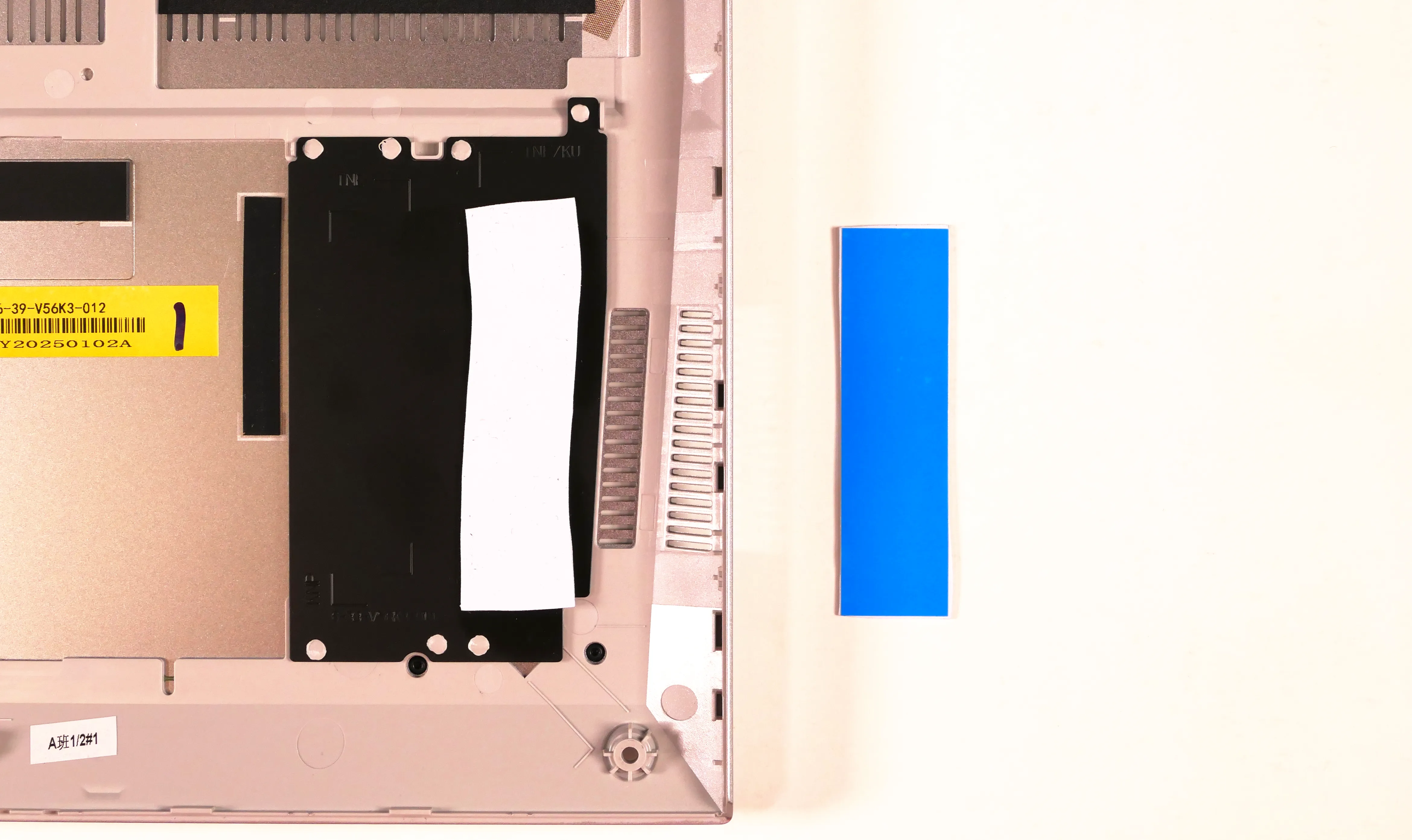
Replacing the battery:
The battery provides primary power whenever the system is unplugged.
Part numbers:
- The battery's model number is
V540BAT-4-80, and the original part number is6-87-V540S-81N01.- Third-party battery sellers may list one or both of these numbers, and may offer other compatible part numbers with the same model number.
- You can also contact System76 to purchase a replacement battery.
Tools required: Cross-head (Phillips) screwdriver
Time estimate: 10 minutes
Difficulty: Easy ●
Steps to replace the battery:
- Follow the steps above to remove the bottom cover.
- Remove the four silver battery screws near the corners of the battery.

- Unplug the white connector (highlighted yellow above) connecting the battery to the motherboard.
- Lift the battery out of the chassis.
- The wireless antennas are routed through plastic channels along the top-left corner of the battery; lift the wires out of the channels while removing the battery.
- Place the new battery into the chassis.
- Feed the wireless antennas back through the new battery's plastic channels.
- Screw the new battery into the chassis.
- When plugging in the new battery, the red wire on the connector is oriented towards the battery, and the black wire is oriented away from the battery.
Replacing the wireless card:
Your Oryx Pro's WiFi and Bluetooth are both handled by the same module. It is a standard M.2 2230 slot with PCIe and USB interfaces (E-key).
Part numbers:
- The standard wireless card is an Intel
AX210NGW.
Tools required: Cross-head (Phillips) screwdriver
Time estimate: 10 minutes
Difficulty: Medium ●
Steps to replace the WiFi/Bluetooth module:
- Follow the steps above to remove the bottom cover.
- Unscrew the wireless card screw holding the card and its wire bracket in place.

- Remove the metal bracket that holds the antenna wires onto the card.
- Gently unplug the two antennas (highlighted red below) by pulling them up and away from the wireless card.
- The wireless card will spring up to a 30° angle after the antennas are detatched.

- Pull the wireless card out of the M.2 slot.
- Insert the new wireless card into the M.2 slot at an angle.
- Push the card down until it's parallel with the motherboard and the end is resting on the screw hole.
- Attach the two antennas by aligning the circular fittings and pressing onto the wireless card. The connectors will snap into place.
- Use caution when attaching the connectors; the pins can bend, break, or snap.
- Place the metal bracket back over the antennas and screw hole.
- Replace the wireless card screw and the bottom panel.
Replacing the CMOS battery:
The CMOS battery supplies power to the system's CMOS chip. UEFI settings and the computer's hardware clock are stored on the CMOS. If your system doesn't boot, you can reset the CMOS to force a low-level hardware reset. If your clock is constantly resetting, it's likely your CMOS battery needs to be replaced.
Warning (ingestion hazard): Keep batteries out of reach of children. Death or serious injury can occur if ingested. If a battery is suspected to be swallowed or inserted inside any part of the body, seek immediate medical attention. In the US, you can also call the National Battery Ingestion Hotline for guidance: +1 (800) 498-8666
Part numbers:
- The CMOS battery is a standard 3V KTS CR2032W battery.
Tools required: Cross-head (Phillips) screwdriver
Time estimate: 15 minutes
Difficulty: Medium ●
Steps to replace the CMOS battery:
- Follow the steps above to remove the bottom cover and, if installed, remove the SSD from slot 1 (closest to the side of the machine).
- Removing the SSD from slot 1 is optional if you're resetting the CMOS but not replacing the CMOS battery.

- Unplug the small white connector that connects the CMOS battery to the motherboard. If you are replacing the battery, gently pull from the sides to pry it up from where it's stuck to the chassis.
- To clear the CMOS, disconnect the main battery, open the lid of the machine, and hold down the power button for at least 15 seconds to discharge any residual energy in the system.
- Reconnect the CMOS battery, reconnect the main battery, and replace the M.2 SSD in slot 1 (if necessary).
- Replace the bottom panel and power up the Oryx Pro. The system may power itself off and on after initial boot; this is normal behavior when the CMOS has been reset.
Replacing the cooling system:
The Oryx Pro 13 uses two fans and a heatsink manufactured as a single assembly.
If the fans become noisy and cleaning them out doesn't fix the issue, you may need a new fan. Contact support to start a warranty claim or parts purchase. These instructions can also be used if physical damage to the heatsink necessitates its replacement.
Thermal paste helps facilitate effective heat transfer between the CPU/GPU and the cooling equipment; depending on your climate and the age of the machine, replacing the thermal paste may improve cooling performance. The thermal paste should generally be replaced whenever the heatsink is removed.
Thermal putty (thicker than thermal paste) is used to bridge the gap between the VRAM chips and the heatsink. Replacing the thermal putty is optional when removing the heatsink. System76 suggests Thermal Grizzly Putty Basic (available at various retailers) or a similar alternative.
Part numbers:
- Heatsink/fan assembly: Peak
6-31-V56NN-102 - Individual fans (may not be available separately):
- Left fan: YingFan
507 NA80080HHT4B10007 - Right fan: YingFan
508 NB800805HHT4B10007
- Left fan: YingFan
Tools required: Cross-head (Phillips) screwdriver, thermal putty spreader (flat plastic tool)
Time estimate: 30 minutes
Difficulty: High ●
Steps to replace the fans/heatsink/thermal paste:
- Follow the steps above to remove the bottom cover.
- Peel back any clear tape that is securing the fan wires.
- If the bottom of the tape extends behind the battery, peel the tape back from the top and leave the bottom attached for ease of reinstallation.
- Remove the silver heatsink and fan screws in the order of the stamped numbers, starting with #1, then #2, and continuing until you have removed #9.
- Do not remove the smaller black screws holding the fan covers onto the fans.

- Unplug the two fan connectors (one white and one black) from the motherboard.
- Remove the heatsink/fans from the case, being careful not to bend the heatsink pipes. It may take some pressure to break the seal of the thermal paste.
- Using a paper towel, remove the existing thermal paste from the CPU and GPU chips, as well as the corresponding points on the heatsink. You may also use a small amount of rubbing alcohol if the old paste is dried or difficult to remove.
- You can optionally remove the thermal putty from the four VRAM chips surrounding the GPU chip if you have replacement thermal putty to install.
- Some thermal paste and/or putty may already be on the motherboard around the chips, or may get onto the motherboard while cleaning the paste/putty off of the chips. Thermal paste and putty is typically not conductive; it's safer to leave excess paste on the board than to risk damaging the board with rough removal.

- Apply a small line of thermal paste directly onto the CPU and GPU chips.
- If you're also replacing the thermal putty, apply the new putty to the four VRAM chips.
- If you aren't replacing the thermal putty, scoop the existing putty (from the chip and the corresponding location on the heatsink) into the center of each VRAM chip using a flat plastic tool.

- Carefully replace the heatsink.
- Replace the silver heatsink and fan screws, starting with #1, then #2, and so on until #9.
- Plug the two fan connectors back into the motherboard.
Replacing the speakers:
The system has two bottom-firing speakers, which can be removed and replaced individually.
Part numbers:
- Left speaker:
- Model number:
V560TNE-L - Part number:
6-23-5V560-0L1
- Model number:
- Right speaker:
- Model number:
V560KNE-R - Part number:
6-23-5V56N-0R1
- Model number:
Tools required: Cross-head (Phillips) screwdriver
Time estimate: 10 minutes
Difficulty: Easy ●
Steps to replace the left speaker:
- Follow the steps above to remove the bottom cover and remove the battery (if installed).
- Unscrew the two speaker screws holding the speaker onto the chassis.
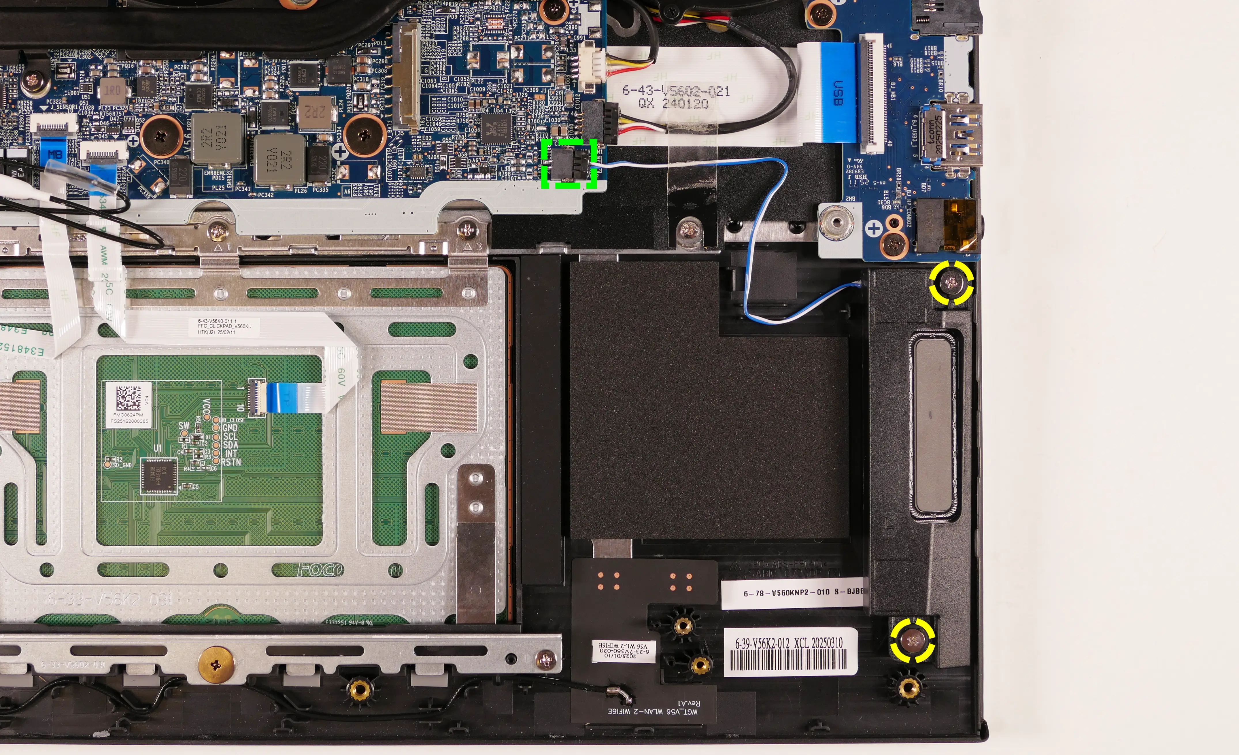
- Peel back the clear tape holding the speaker's wire to the chassis.
- Disconnect the speaker connector from the motherboard.
- Replace the speaker, plug in the speaker connector, and secure the wire with the clear tape on the chassis.
- Replace the main battery and the bottom cover.
Steps to replace the right speaker:
- Follow the steps above to remove the bottom cover.
- Unscrew the two speaker screws holding the speaker onto the chassis.
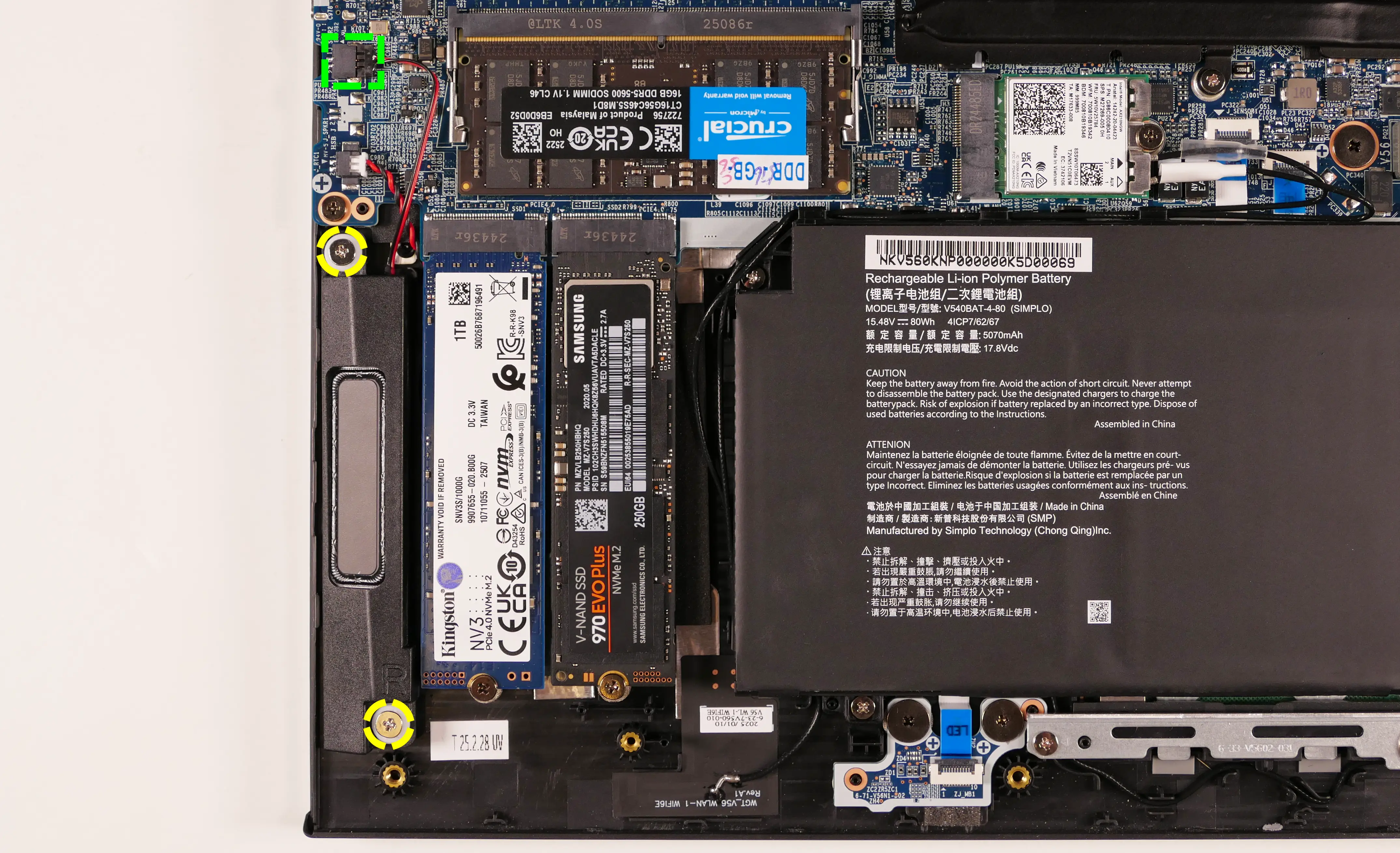
- Disconnect the speaker connector from the motherboard.
- Replace the speaker, plug in the speaker connector, and replace the bottom cover.
Replacing the keyboard:
The keyboard can be replaced if its switches or electronics have been damaged.
Warning: The keyboard is held in by two strips of adhesive in addition to one of the bottom panel screws and the perimeter clips. The adhesive may be difficult to remove from the keyboard and/or case, and while the keyboard should still be functional if removed carefully, it is possible that permanent aesthetic damage will occur to the bottom side of the keyboard during removal. Removal is not recommended unless the keyboard is malfunctioning.
Part numbers:
- The keyboard's model number is
CVM22K33US9430H, and its part number is6-80-V5610-01B-1, also known as6-V560KNP-KB-MCL-US.- Keyboards shipped by System76 include a custom-printed Super key.
Tools required: Cross-head (Phillips) screwdriver
Time estimate: 20 minutes
Difficulty: Hard ●
Steps to replace the keyboard:
- Follow the steps above to remove the bottom cover, remove the heatsink, and, if installed, remove the SSD from slot 2 (closest to the battery).
- Replacing the thermal paste is recommended if the heatsink is removed.
- It may be possible to pull the adhesive out from behind the heatsink without removing the heatsink using a tweezers or a small screwdriver, but the adhesive is not fed through the heatsink by default due to its shape and size.
- Pull the keyboard adhesive out of the machine to detatch it from the keyboard.
- The adhesive strip access points are highlighted green below.
- Pull each adhesive strip slowly to avoid breaking it. Grasp farther down the strip as it comes out of the machine (don't pull the end far away from the machine).
- If an adhesive strip breaks, remove as much of it as possible. The keyboard can be reinstalled without the adhesive strips.

- Open the lid slightly and place the machine on its side.
- Push the keyboard out of the chassis from below through the gaps in the chassis (highlighted red above).

- Set the machine back down and raise the keyboard away from the chassis. The larger ribbon cable is for the keyboard, while the smaller ribbon cable is for the keyboard backlight.
- To avoid getting thermal paste on your work surface, you can re-mount the heatsink while the machine's still turned on its side after pushing the keyboard's perimeter tabs out of the chassis.

- Flip the black latches upwards to free the ribbon cables.
- Pull the ribbon cables out of the connectors.
- Remove the keyboard and replace it with the new one.
- Carefully slide both ribbon cables into their connectors.
- Flip the black latches back into place to secure the ribbon cables.
- (Optional) Replace the keyboard adhesive strips on the chassis, sliding the tabs at the end through the adhesive strip access points.
- For the larger adhesive strip, use the rightmost access slot (labeled
KNE).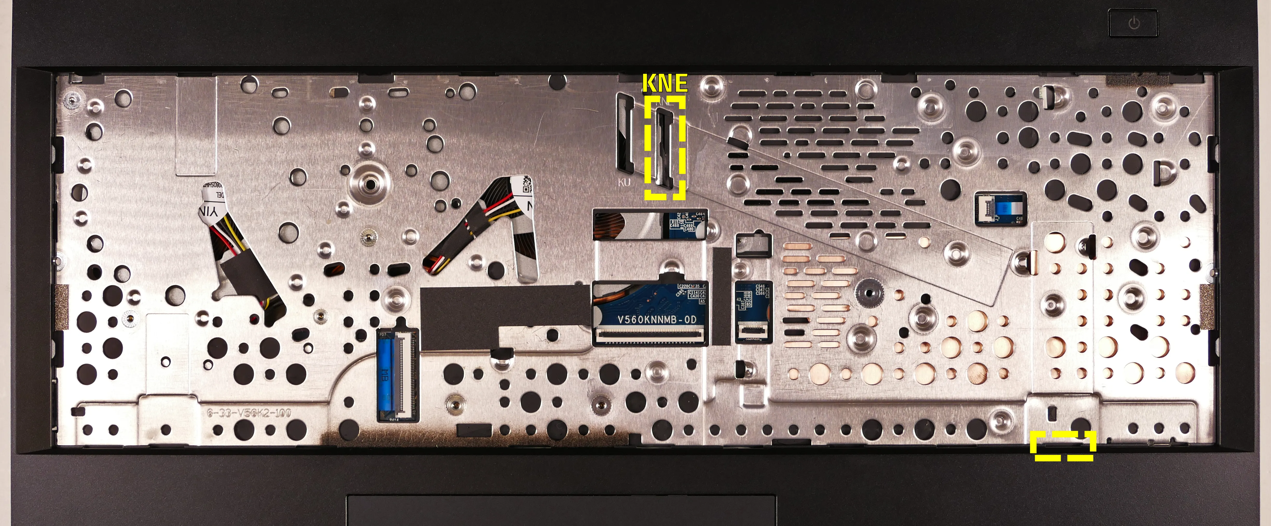
- For the larger adhesive strip, use the rightmost access slot (labeled
- Place the keyboard back into position, starting with the tabs on the bottom edge.
- Secure the rest of the keyboard by pressing down on each of its edges.
- Turn the machine lid-side down again and replace the bottom panel.
Pangolin (pang15)
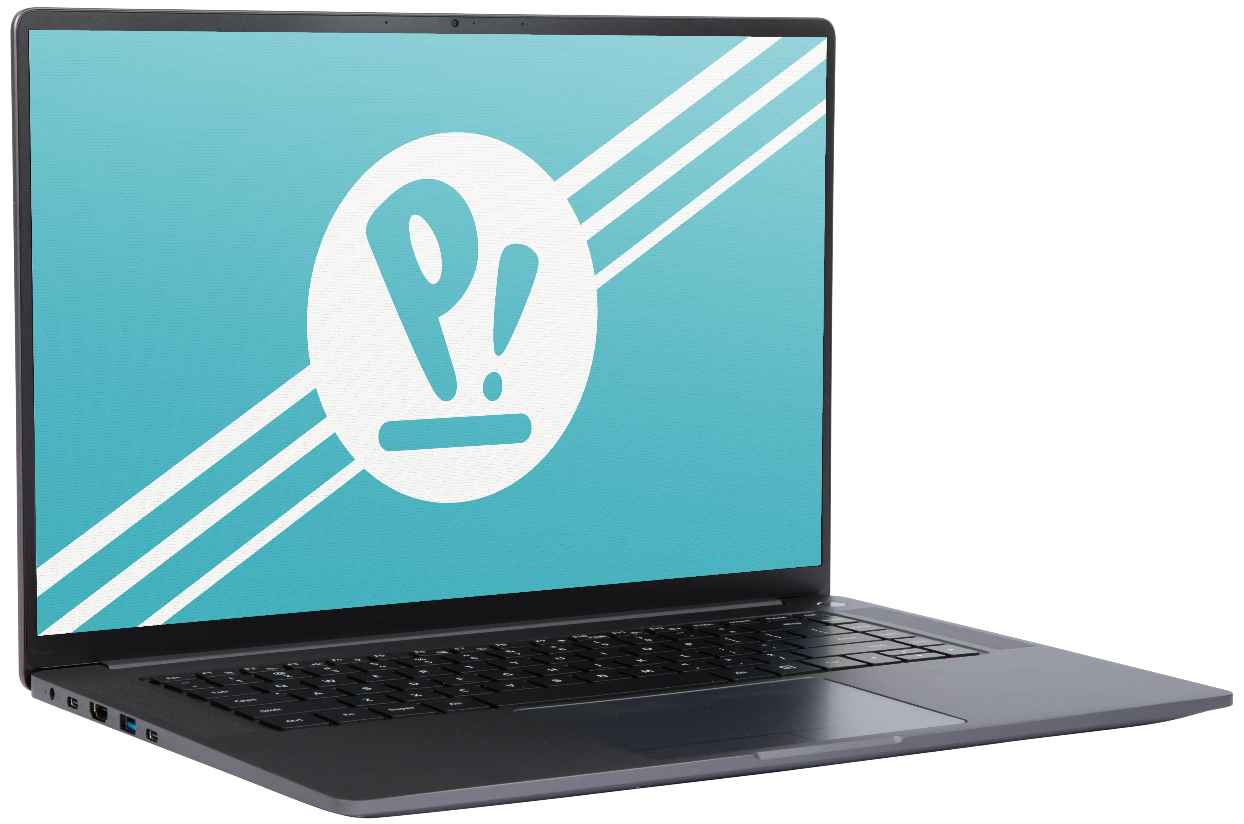
The System76 Pangolin is a laptop with the following specifications:
- CPU
- Supports AMD Ryzen (Hawk Point) Mobile CPUs
- BIOS
- Winbond W25R256JW flash chip
- WSON-8 form factor
- Programmed with System76 firmware (non-open)
- Winbond W25R256JW flash chip
- EC
- ITE IT5571
- Programmed with non-open EC firmware
- Graphics
- GPU: AMD Radeon 780M
- eDP display: 16.1" 2560×1600@120Hz LCD
- LCD panel: BOE NE160QDM-NY2 (or equivalent)
- Brightness: 350 nits (cd/m²)
- sRGB color coverage: 100%
- LCD panel: BOE NE160QDM-NY2 (or equivalent)
- External video output:
- 1x HDMI 2.0
- 2x DisplayPort 1.4 over USB-C
- Memory
- Up to 96GB (2x48GB) dual-channel DDR5 @ 5600 MHz
- Networking
- WiFi 6E/Bluetooth 5.2 (soldered)
- Model: AzureWave AW-XM514NF
- Chipset: MediaTek MT7922A12L
- WiFi 6E/Bluetooth 5.2 (soldered)
- Power
- 100W USB-C charging
- Lower-powered chargers supported with performance throttling
- Included USB-C charger: Dongguan Aohai A879-200500C-US1
- 100W (20V, 5A) DC-in port
- Barrel size:
- Outer port diameter: 3.5mm
- Inner pin diameter: 1.35mm
- Barrel length: 10mm
- Barrel charger not included
- Barrel size:
- 57.75Wh 4-cell Lithium-Ion battery
- Model number: U716849PHV-4S1P
- 100W USB-C charging
- Sound
- Internal speakers & microphone
- Combined headphone & microphone 3.5mm jack
- HDMI & USB-C DisplayPort audio
- Storage
- 2x M.2 (PCIe NVMe Gen 4)
- MicroSD card reader
- USB
- 1x USB 4.0 Type-C
- Supports DisplayPort over USB-C
- Supports USB-C charging (USB-PD)
- Does not support Thunderbolt
- 1x USB 3.2 Gen 2 Type-C
- Supports DisplayPort over USB-C
- Does not support USB-C charging (USB-PD)
- Does not support Thunderbolt
- 3x USB 3.2 Gen 1 Type-A
- 1x USB 4.0 Type-C
- Dimensions
- 1.8cm x 35.6cm x 24.6cm, 1.73kg
Pangolin (External Overview)
Left side:

Right side:

Front side:

Back side:

Keyboard & touchpad:
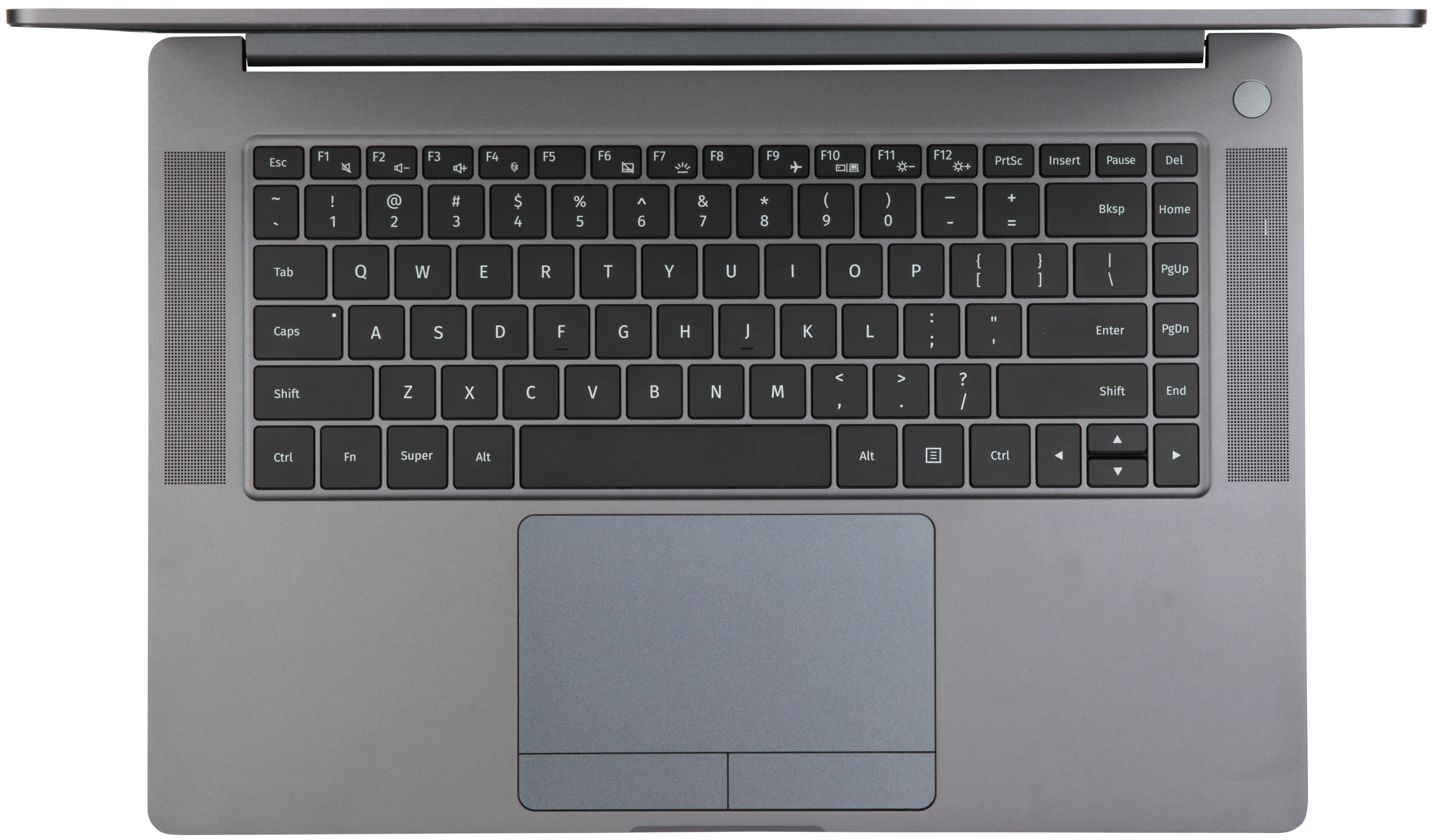
Lid:
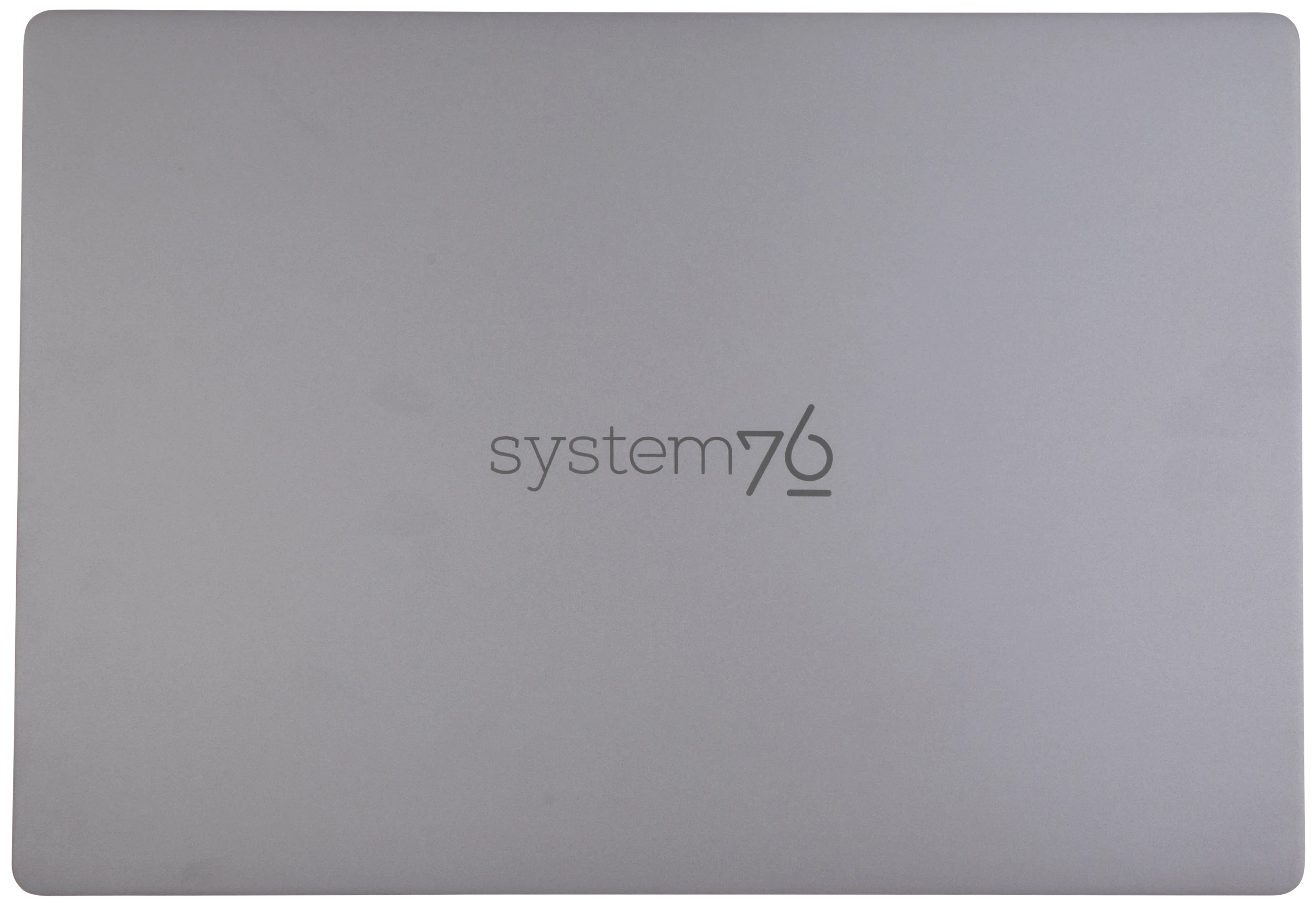
Materials
| Part | Material | Part Number |
|---|---|---|
| LCD back cover (lid) | Aluminum | 02.SKD.NM16AHFTX00 |
| LCD front cover (bezel) | Plastic | 02.SKD.NM16AHFTX00 |
| Top case (palm rests/port covers) | Aluminum | 02.SKD.NM16AHFTX01 |
| Bottom panel | Aluminum | 02.SKD.NM16AHFTX02 |
LED indicators:
| Icon | State | Description |
|---|---|---|
 | Green | Fully charged |
| Red | Charging | |
| Off | Not charging (disconnected) | |
 | On | Webcam disabled (privacy mode on) |
| Off | Webcam enabled (privacy mode off) |
Keyboard shortcuts
| Key | Shortcut | Action |
|---|---|---|
 | Fn+F1 | Mute |
 | Fn+F2 | Volume down |
 | Fn+F3 | Volume up |
 | Fn+F4 | Mute/unmute microphone |
 | Fn+F6 | Toggle trackpad |
 | Fn+F7 | Cycle keyboard brightness |
 | Fn+F9 | Toggle airplane mode |
 | Fn+F10 | Toggle displays |
 | Fn+F11 | Screen brightness down |
 | Fn+F12 | Screen brightness up |
Pangolin (Internal Overview)
Bottom components and connectors:

- RAM slots are highlighted in maroon
- RAM sticks are covered with protective plastic
- M.2 SSDs are highlighted in dark green
- Wireless card is highlighted in dark blue
- LCD panel connector is highlighted in red
- Covered by black protective tape
- CMOS battery connector is highlighted in yellow
- Main battery connector is highlighted in purple
- Fan connectors are highlighted in orange
- Speaker connectors are highlighted in cyan
- Left speaker connector (on the right side) is covered by black protective tape
- Keyboard connector is highlighted in light green
- Keyboard backlight connector is highlighted in pink
- Covered by black protective tape
- Touchpad connector is highlighted in white
- Covered by black protective tape
- BIOS flash chip is highlighted in black
- Covered by the CPU heatsink pipe
Pangolin (Parts & Repairs)
Many components in your Pangolin can be upgraded or replaced as necessary. Follow these step-by-step guides for instructions:
- Removing the bottom cover
- Replacing the RAM
- Replacing an M.2/NVMe SSD
- Removing the battery
- Reseating the WiFi/Bluetooth antennas
- Replacing the CMOS battery
- Replacing the fans/heatsink/thermal paste
- Replacing the speakers
Removing the bottom cover:
Removing the cover is required to access the internal components. Prior to removing the cover, ensure the AC power is unplugged and all peripherals (including SD cards and USB drives) are unplugged or removed from the system.
Part numbers:
- The bottom panel's part number is
02.SKD.NM16AHFTX02.
Tools required: Cross-head (Phillips) screwdriver
Time estimate: 5 minutes
Difficulty: Easy ●
Steps to remove the bottom cover:
- Place the machine lid-side down.
- Use a soft surface (such as a towel) to avoid scratches.
- Remove the 7 bottom panel screws.
- The back-center screw (highlighted red below) is longer than the rest of the screws.
- The front four screws are mounted at an angle into the machine; hold the screwdriver at an angle for the easiest removal/installation.

- Lift the bottom panel off, starting from the hinges in the back.
Replacing the RAM:
The Pangolin 15 supports up to 96GB (2x48GB) of DDR5 SO-DIMMs running at 5600MHz. If you've purchased new RAM, need to replace your RAM, or are reseating your RAM, follow these steps.
Tools required: Cross-head (Phillips) screwdriver
Time estimate: 10 minutes
Difficulty: Easy ●
Steps to replace the RAM:
- Follow the steps above to remove the bottom cover.
- Remove the black protective covers from the RAM slots, shown on the left below.
- Alternatively, you can pull the outer ends of the covers up and hold them away from the RAM sticks while replacing them instead of entirely removing the covers from the slots.

- Press the small tabs on both sides of the RAM simultaneously. The RAM should spring up to an angle.
- Remove the RAM from the slot.
- Insert the new RAM (or reseat the existing RAM) by placing it into the keyed slot and pressing down until it clicks into place.
Replacing an M.2/NVMe SSD:
This model supports two M.2 SSDs. Both slots support PCIe NVMe Generation 4 connections and M.2 size 2280.
Tools required: Cross-head (Phillips) screwdriver
Time estimate: 3 minutes
Difficulty: Easy ●
Steps to replace the M.2 drive:
- Follow the steps above to remove the bottom cover.
- Unscrew the retainer screw opposite the M.2 slot.

- Remove the existing M.2 drive by pulling it out of the slot.
- If replacing an M.2 drive, slowly peel the light blue thermal pad off of the old drive, then place it on the new drive.
- If you ordered less than two drives when purchasing your system, the additional thermal pad will be included in the box.
- M.2 thermal pads are optional, and drives can be used without thermal pads if the pads are lost or unable to be transferred. Without the thermal pad, performance may be throttled to avoid overheating.
- Insert the new M.2 drive into the slot and hold it in place.
- Replace the retainer screw.
Replacing the battery:
The battery provides primary power whenever the system is unplugged.
Part numbers:
- The battery's model number is
U716849PHV-4S1P, and the original part number is4ICP8/68/49.- Third-party battery sellers may list one or both of these numbers, and may offer other compatible part numbers with the same model number.
- You can also contact System76 to purchase a replacement battery.
Tools required: Cross-head (Phillips) screwdriver
Time estimate: 10 minutes
Difficulty: Easy ●
Steps to replace the battery:
- Follow the steps above to remove the bottom cover.
- Remove the seven battery screws, highlighted cyan below.

- Unplug the battery connector (highlighted green above) and lift the battery out of the chassis.
- Wires may be routed through the hooks on the left side of the battery. Free the wires, and push them back into the hooks when installing the battery again.
- When plugging in the battery, the red wires go on the left, and the black wires go on the right.
Reseating the wireless antenna connectors:
Your Pangolin's WiFi and Bluetooth are both handled by the same module, which is soldered to the Pangolin motherboard. If you are experiencing wireless connectivity issues and would like to reseat the wireless antenna connectors, you can do so using the instructions below.
Part numbers:
- The built-in wireless card is an AzureWave
AW-XM514NF.- The wireless card chipset is a MediaTek
MT7922A12L.
- The wireless card chipset is a MediaTek
- The motherboard's model number is
EM_APX938_V2.0.
Tools required: Cross-head (Phillips) screwdriver
Time estimate: 12 minutes
Difficulty: Medium ●
Steps to replace the WiFi/Bluetooth module:
- Follow the steps above to remove the bottom cover.
- Locate the wireless module. Remove the clear cover securing the wires and card (shown on the left below).

- Gently remove the two antennas (highlighted red above) by pulling them up and away from the wireless card.
- Re-attach the two antennas by aligning the circular fittings and pressing onto the wireless card. The connectors will snap into place. Use caution when attaching the connectors; the pins can bend, break, or snap.
Replacing the CMOS battery:
The CMOS battery supplies power to the system's CMOS chip. UEFI settings and the computer's hardware clock are stored on the CMOS. If your system doesn't boot, you can reset the CMOS to force a low-level hardware reset. If your clock is constantly resetting, it's likely your CMOS battery needs to be replaced.
Warning (ingestion hazard): Keep batteries out of reach of children. Death or serious injury can occur if ingested. If a battery is suspected to be swallowed or inserted inside any part of the body, seek immediate medical attention. In the US, you can also call the National Battery Ingestion Hotline for guidance: 1 (800) 498-8666
Part numbers:
- The CMOS battery is a standard 3V CR2032 battery. The stock battery is Malak brand.
Tools required: Cross-head (Phillips) screwdriver
Time estimate: 10 minutes
Difficulty: Medium ●
Steps to replace the CMOS battery:
- Follow the steps above to remove the bottom cover.
- Unplug the white connector attaching the CMOS battery to the motherboard (highlighted cyan below.)

- If you are replacing the CMOS battery, carefully peel it away from the adhesive holding it to the chassis.
- To clear the CMOS, disconnect the main battery, open the lid of the machine, and hold down the power button for at least 15 seconds to discharge any residual energy in the system.
- Re-connect the CMOS battery and the main battery, and replace the bottom panel.
- When connecting the CMOS battery, the red wire goes on the left, and the black wire goes on the right.
- Power up the machine. The system may power itself off and on after initial boot; this is normal behavior when the CMOS has been reset.
Replacing the cooling system:
The Pangolin 15 has a fan and heatsink assembly to cool the CPU. The fans and heatsink are held together with adhesive; it is possible to replace the fans individually, but removing the entire assembly is recommended to perform service.
If the fan becomes noisy and cleaning it out doesn't fix the issue, you may need a new fan. Contact support to start a warranty claim or parts purchase.
Depending on your climate and the age of the machine, it may be necessary to apply new thermal paste between the CPU and the heatsink. Thermal paste helps facilitate effective heat transfer between the CPU and the cooling equipment.
Part numbers:
- The heatsink's part number is
01.WW7.APX938ARM00. - The left fan is a Joray
BF070E12P (S-0592), and its part number is01.SS9.APX938DTH00. - The right fan is a Joray
BF080D12P (S-0593), and its part number is01.SS9.APX938DTH01.
Tools required: Cross-head (Phillips) screwdriver, thermal paste
Time estimate: 20 minutes
Difficulty: High ●
Steps to replace the fan/heatsink/thermal paste:
- Follow the steps above to remove the bottom cover.
- Slowly peel off the black coverings and their connecting strip from the heatsink, highlighted green below.
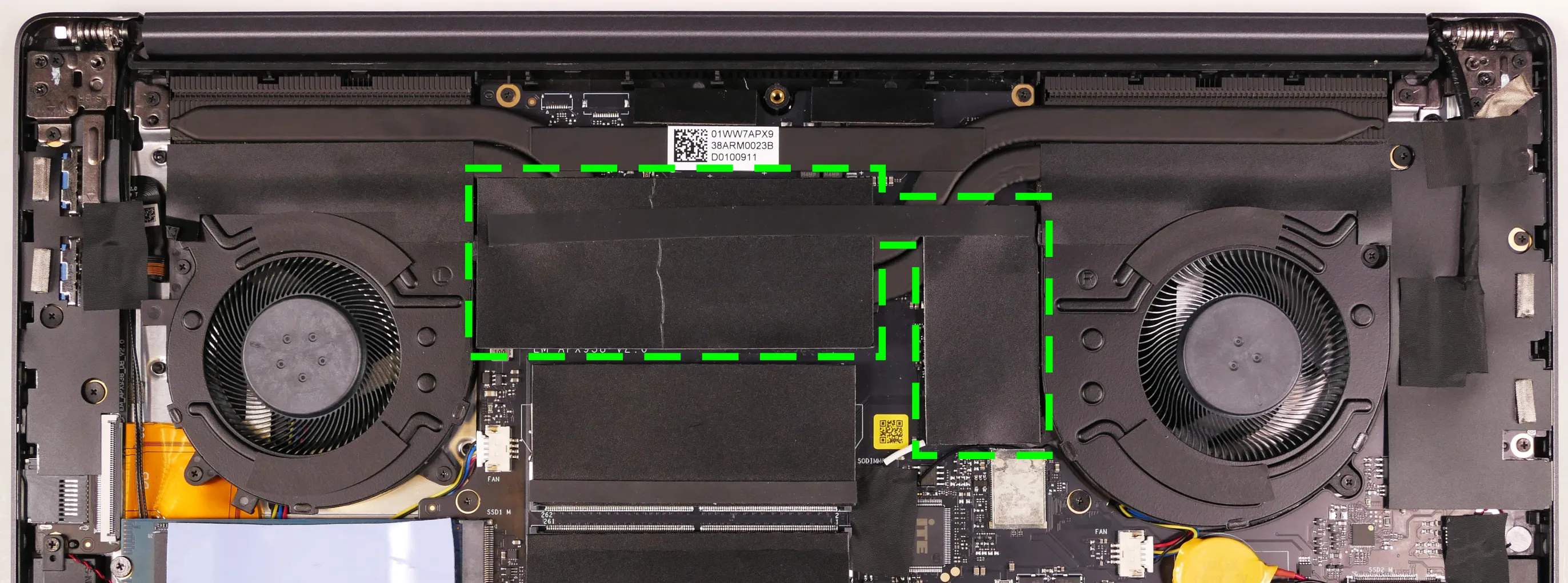
- Remove the six fan screws, highlighted green below.

- Unplug the fan connectors, highlighted cyan above.
- Unscrew the four heatsink screws, highlighted red above.
- The heatsink screws are held captive and will not come out of the heatsink.
- Remove the fan and heatsink assembly from the system, being careful not to bend the heatsink pipe. It may take some pressure to break the seal of the thermal paste.
- The fans are held onto the heatsink with adhesive strips on both the top and bottom; if they come loose, place them back into position between the strips before reinstalling the fan/heatsink assembly.
- Using a paper towel, remove the existing silver thermal paste. You may also use a small amount of rubbing alcohol if the old paste is dried or difficult to remove.
- The pink thermal pads do not need to be removed.

- After cleaning the CPU and heatsink, apply a small line of thermal paste directly onto the CPU chip.

- Carefully replace the heatsink.
- Tighten the four heatsink screws.
- Replace the fan screws, plug in the fan connectors, stick the black coverings back onto the heatsink pipes, and replace the bottom panel.
Replacing the speakers:
The system has four speakers (two top-firing tweeters and two bottom-firing woofers). The left and right channels can be replaced independently.
Part numbers:
- Left speakers (right side of machine when viewing from below):
- Tweeter:
GS-NM16TG-L - Woofer:
GS-NM16TG-L-2
- Tweeter:
- Right speakers (left side of machine when viewing from below):
- Tweeter:
GS-NM16TG-R - Woofer:
GS-NM16TG-R-2
- Tweeter:
Tools required: Cross-head (Phillips) screwdriver
Time estimate: 10 minutes
Difficulty: Medium ●
Steps to replace the right speakers:
- Follow the steps above to remove the bottom cover.
- Unplug the
SPK1connector, highlighted cyan below.- Peel back any black tape covering the wires stemming from this connector.
- This can alternatively be done after freeing the speakers.
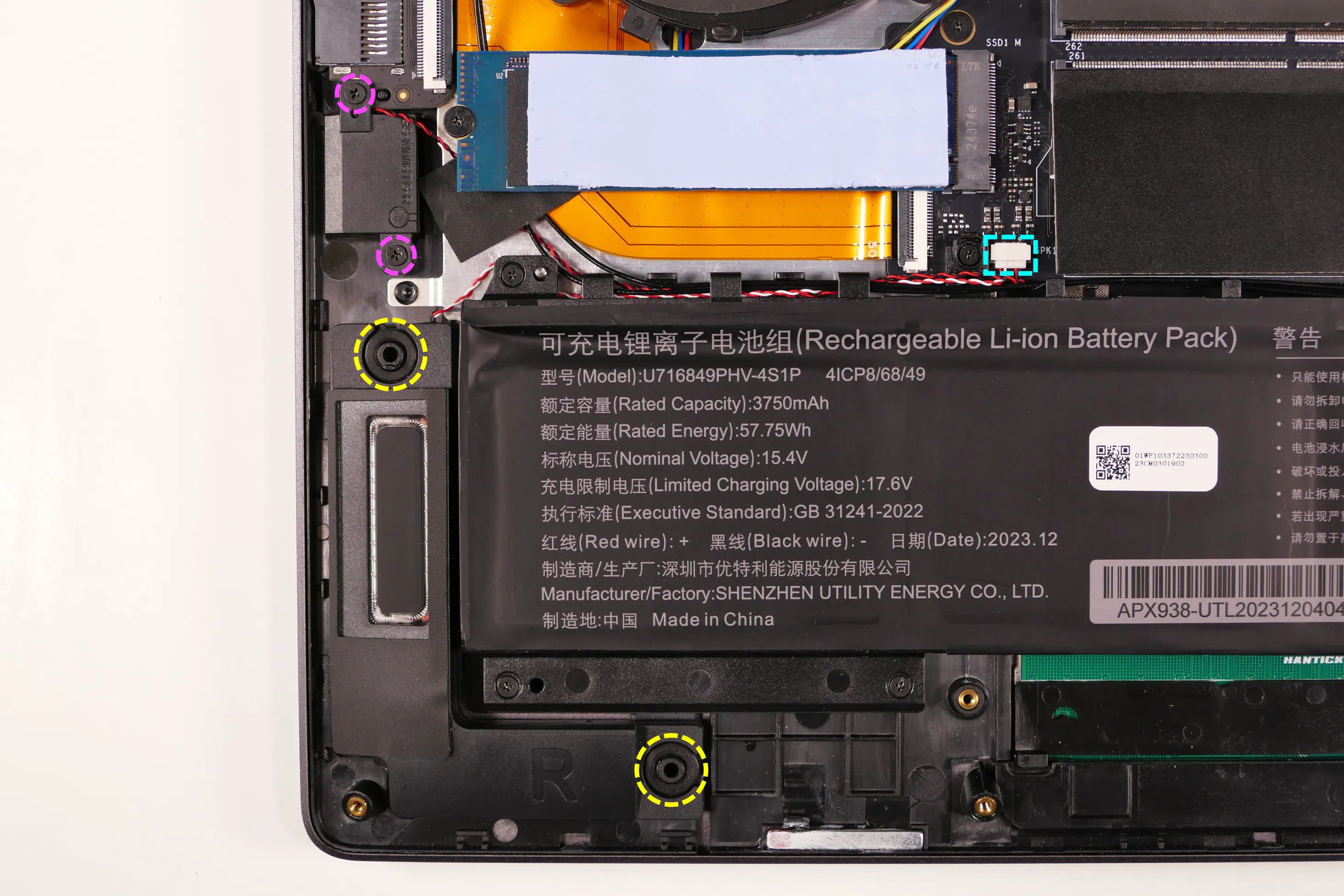
- Unscrew the right tweeter screws, highlighted pink above.
- Pull the right woofer off of the plastic mounting posts (highlighted yellow above), then lift the speakers out of the machine.
- The woofer wire is not routed underneath the battery by default, but may become routed underneath the battery after the battery is replaced. If this is the case, it may be necessary to remove the battery before removing the right woofer.
- Slide the new woofer onto the plastic posts, screw the new tweeter in, and connect the
SPK1connector. - Replace the black tape and bottom panel.
Steps to replace the left speakers:
- Follow the steps above to remove the bottom cover.
- Remove the black tape (highlighted green below) covering the
SPK2connector and the left tweeter.
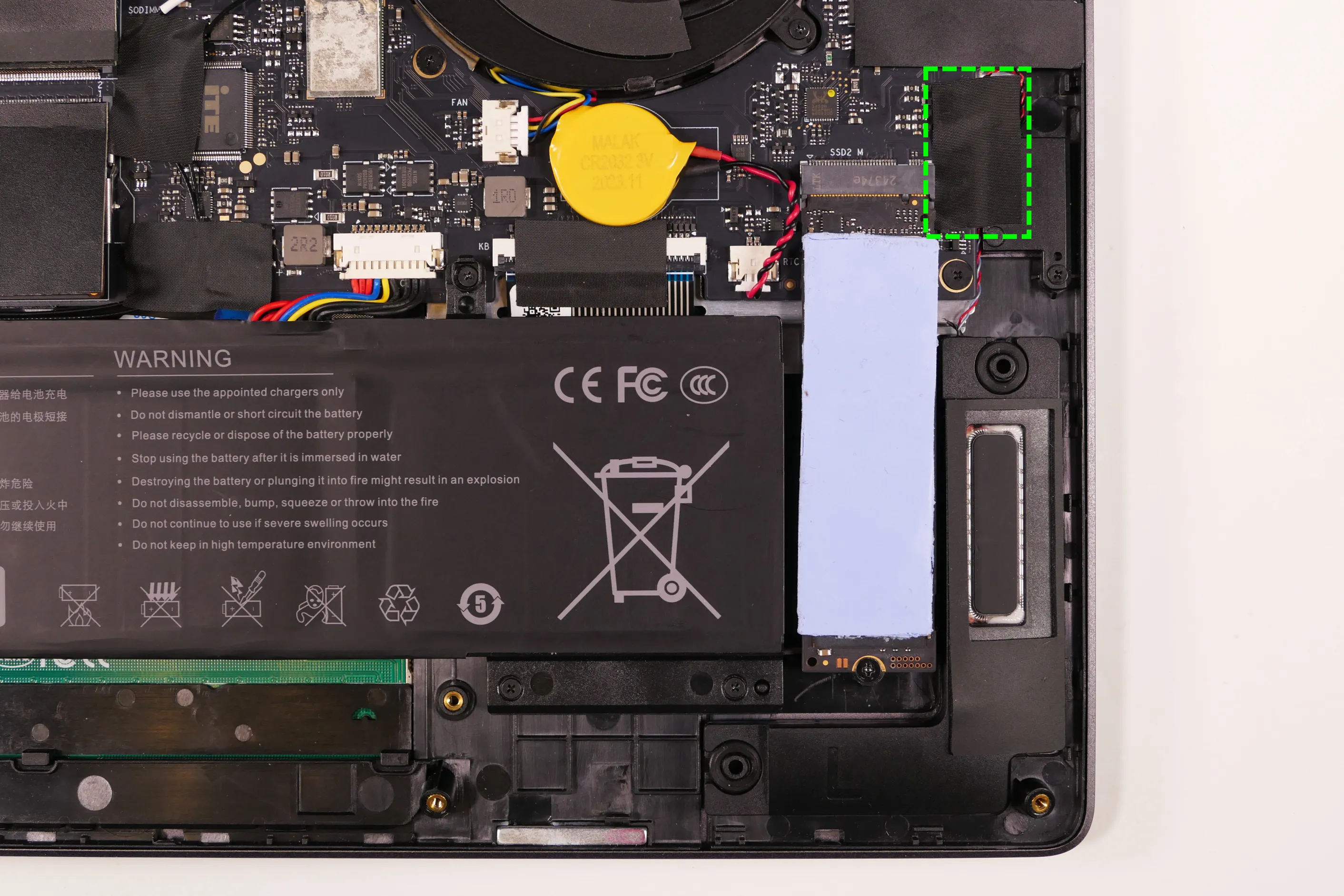
- Disconnect the
SPK2connector from the motherboard, highlighted cyan below.- This can alternatively be done after freeing the speakers.
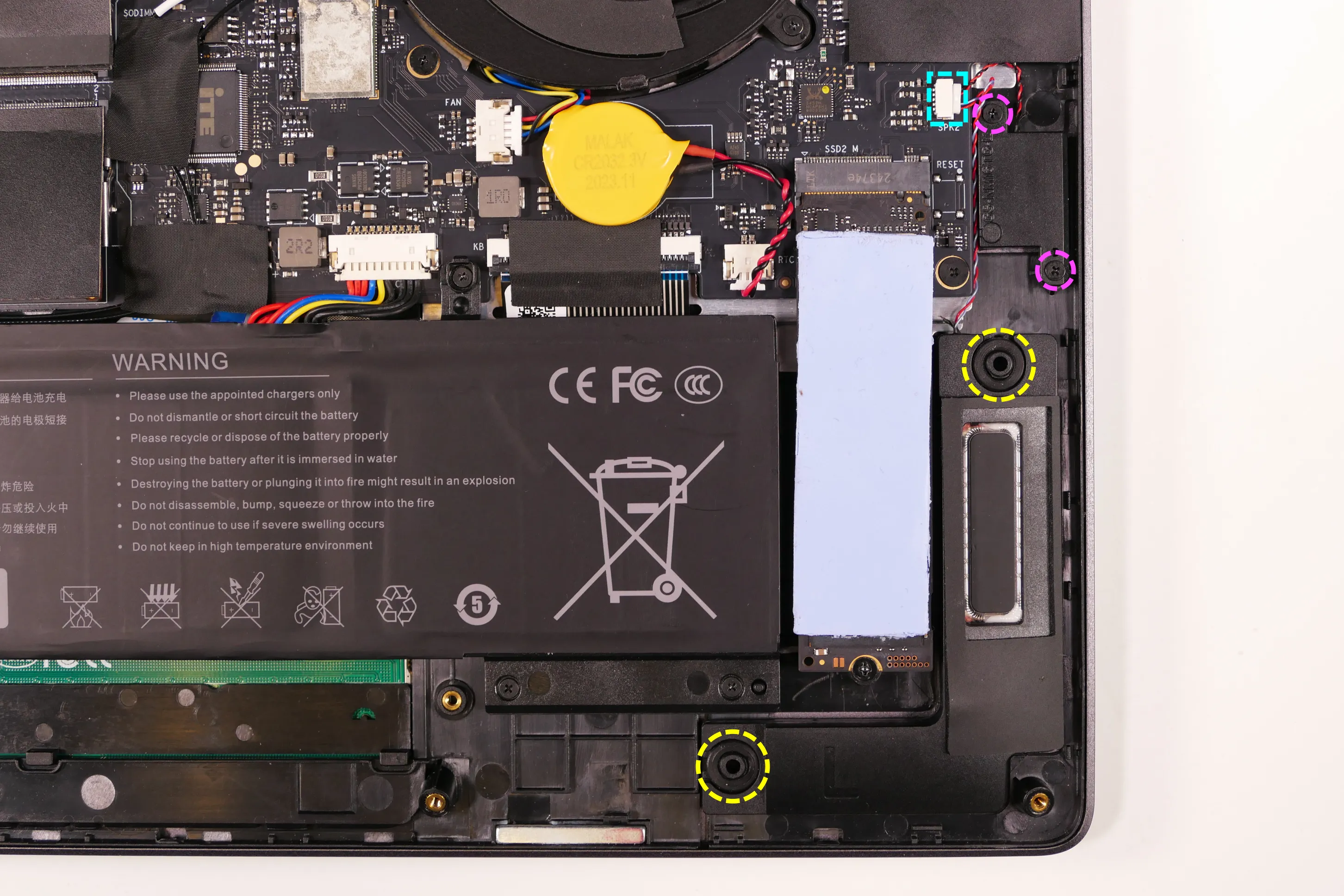
- Unscrew the left tweeter screws, highlighted pink above.
- Pull the left woofer off of the plastic mounting posts (highlighted yellow above), then lift the speakers out of the machine.
- Slide the new woofer onto the plastic posts, screw the new tweeter in, and connect the
SPK2connector. - Replace the black tape and bottom panel.
Serval WS (serw14)
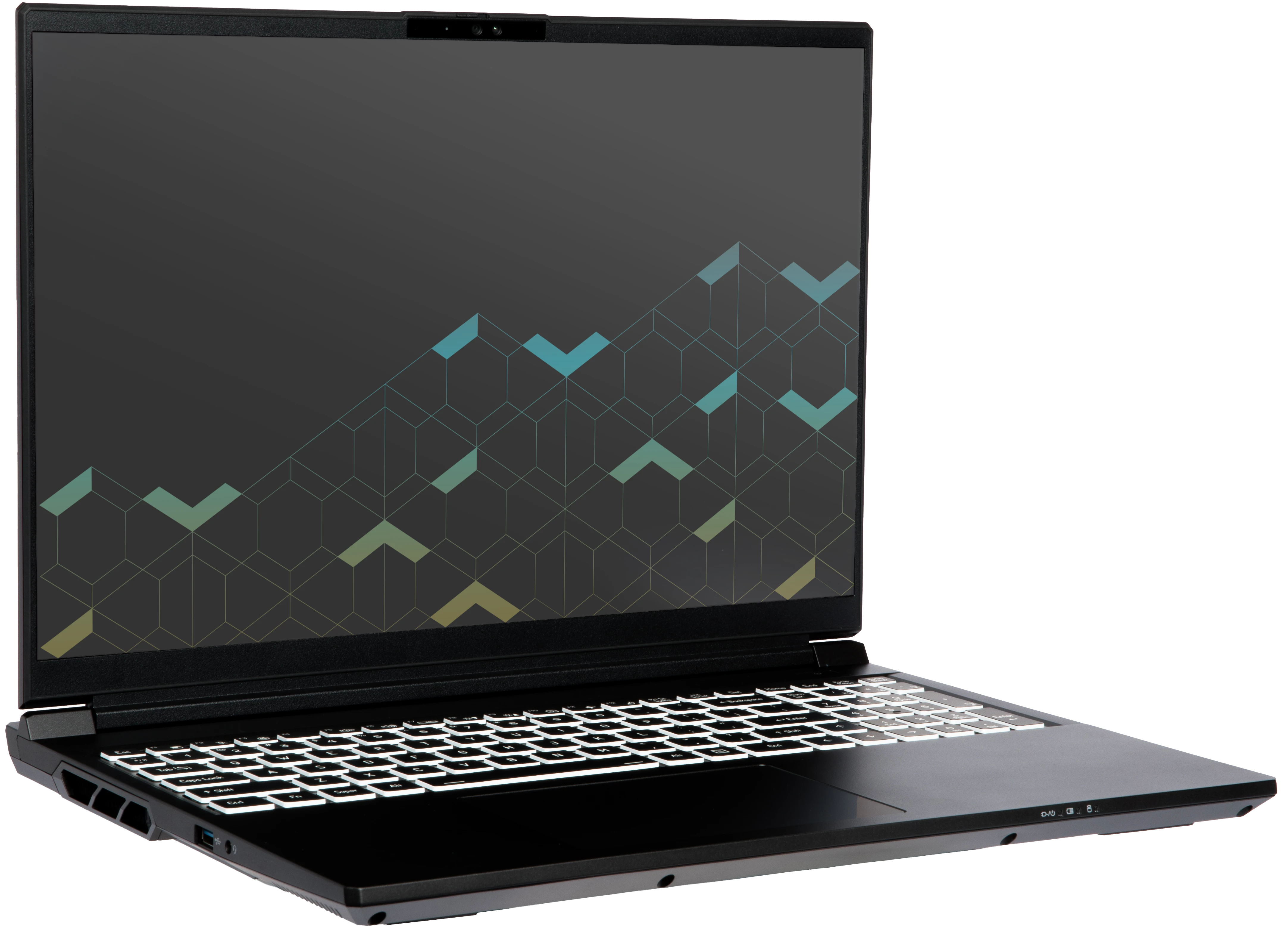
The System76 Serval WS is a laptop with the following specifications:
- CPU
- Supports Intel Core Ultra 2nd generation (Arrow Lake) CPUs
- Chipset
- BIOS
- Flash chip:
- XMC XM25QU256C, GigaDevice GD25LB256FYIG, or equivalent
- WSON-8 form factor
- Programmed with System76 firmware (non-open)
- Flash chip:
- EC
- ITE IT5570E
- Programmed with non-open EC firmware
- Graphics
- GPU options:
- NVIDIA GeForce RTX 5070 Ti
- eDP display options:
- 16" 2560x1600@300Hz LCD
- LCD panel: BOE NE160QDM-NZL (or equivalent)
- Brightness: 500 nits (cd/m²)
- Color coverage:
- DCI-P3: 81%
- sRGB: 100%
- Defaults to 240Hz due to iGPU limitation
- Change "Display Mode" to "Discrete GPU" in BIOS for 300Hz
- LCD panel: BOE NE160QDM-NZL (or equivalent)
- 16" 2560x1600@240Hz LCD
- LCD panel: BOE NE160QAM-NZ1 (or equivalent)
- Brightness: 500 nits (cd/m²)
- Color coverage:
- DCI-P3: 100%
- sRGB: 100%
- LCD panel: BOE NE160QAM-NZ1 (or equivalent)
- 16" 2560x1600@300Hz LCD
- External video outputs:
- 1x HDMI 2.1
- 2x DisplayPort 2.0 over USB-C
- GPU options:
- Memory
- Up to 96GB (2x48GB) dual-channel DDR5 SO-DIMMs @ 5600 MHz
- Networking
- 2.5-Gigabit Ethernet
- M.2 PCIe/CNVi WiFi/Bluetooth:
- Intel Wi-Fi 7 BE200
- Bluetooth 5.4
- Intel Wi-Fi 7 BE200
- Power
- 230W (20V, 11.5A) DC-in port
- Barrel size: 5.5mm (outer), 2.5mm (inner)
- Included AC adapter:
- FSP FSP230-ACBS3
- LiteOn PA-1231-26
- ...or other equivalent
- 80Wh 8-cell Lithium-Ion battery
- Model number: X560BAT-4-80
- 230W (20V, 11.5A) DC-in port
- Sound
- Internal speakers & microphone
- Combined headphone & microphone 3.5mm jack
- HDMI, USB-C DisplayPort audio
- Storage
- 1x M.2 PCIe NVMe Gen 5
- 2x M.2 PCIe NVMe Gen 4
- MicroSD card reader
- USB
- 2x USB Type-C with Thunderbolt 4
- Both ports support DisplayPort over USB-C
- Both ports support USB-C charging (USB-PD)
- 2x USB 3.2 Gen 2 Type-A
- 2x USB Type-C with Thunderbolt 4
- Dimensions
- 35.585cm x 27.102cm x 1.981cm, 2.25kg
Serval WS (External Overview)
Left side:

Right side:

Front side:

Back side:

Keyboard & touchpad:

Lid:

Materials:
| Part | Material | Part Number |
|---|---|---|
| LCD back cover (lid) | Aluminum | 6-39-X5601-022 |
| LCD front cover (bezel) | Plastic | 6-39-X5601-012 |
| Top case (palm rests/port covers) | Aluminum | 6-39-X5602-012 |
| Bottom panel | Aluminum | 6-39-X5603-012 |
LED indicators
The Serval WS has the following LED indicators:
| Icon | Color | Description |
|---|---|---|
 | Orange | Powered off, DC power plugged in |
| Green | Powered on | |
| Blinking green | Sleeping (suspended) | |
 | Orange | Battery charging |
| Green | Battery fully charged | |
| Blinking orange | Battery critically low | |
 | Green | Storage drive activity |
Keyboard Shortcuts
The Serval WS has the following actions available using the Fn and Function keys:
| Key | Shortcut | Action |
|---|---|---|
 | Fn+F1 | Toggle trackpad |
 | Fn+F2 | Toggle microphone mute |
 | Fn+F3 | Mute |
 | Fn+F5 | Volume down |
 | Fn+F6 | Volume up |
 | Fn+F7 | Toggle displays |
 | Fn+F8 | Screen brightness down |
 | Fn+F9 | Screen brightness up |
 | Fn+F10 | Toggle webcam |
 | Fn+F11 | Toggle airplane mode |
 | Fn+F12 | Suspend |
 | Fn+` | Play/Pause |
 | Fn+* | Toggle keyboard backlight |
 | Fn+/ | Cycle keyboard color |
 | Fn+- | Decrease keyboard brightness |
 | Fn++ | Increase keyboard brightness |
| 1 | Fn+1 | Toggle fan between max/automatic |
Serval WS (Internal Overview)
Bottom components and connectors:

- LCD panel connector (under the heatsink) is highlighted in light green
- Webcam/microphone connector (under the heatsink) is highlighted in brown
- Keyboard adhesive access point is highlighted in pink
- M.2 SSDs are highlighted in dark green
- Slot 1 (closest to the fan) supports PCIe NVMe Gen 5
- Slots 2 and 3 (closest to the battery) support PCIe NVMe Gen 4
- Wireless card (under SSD slot 4) is highlighted in cyan
- Fan connectors are highlighted in orange
- CMOS battery connector (under SSD slot 2 and the main battery) is highlighted in purple
- Speaker connectors are highlighted in yellow
- BIOS flash chip (U81) is highlighted in black
- Main battery connector is highlighted in red
- RAM is highlighted in white
Under-keyboard components and connectors:

- Touchpad connector is highlighted in pink
- Keyboard connector is highlighted in yellow
- Keyboard backlight connector is highlighted in green
- Keyboard adhesive access slot is highlighted in cyan
- Power button/LED connector is highlighted in red
Serval WS (Parts & Repairs)
Many components in your Serval WS can be upgraded or replaced as necessary. This page uses photos of the 15" model, but screw counts, general component locations, and other details are the same on the 17" model unless otherwise noted.
- Removing the bottom cover
- Replacing the battery
- Replacing the RAM
- Replacing an M.2/NVMe SSD
- Replacing the WiFi/Bluetooth module
- Replacing the CMOS battery
- Replacing the fans/heatsink/thermal paste
- Replacing the keyboard
- Replacing the speakers
Removing the bottom cover:
Removing the cover is required to access the internal components. Prior to removing the cover, ensure the AC power is unplugged and all peripherals (including SD cards and USB drives) are unplugged or removed from the system.
Part numbers:
- Bottomm panel:
6-39-X5603-012
Tools required: Cross-head (Phillips) screwdriver
Time estimate: 5 minutes
Difficulty: Easy ●
Steps to remove the bottom cover:
- Place the machine lid-side down.
- Use a soft surface (such as a towel) to avoid scratches.
- Remove the 14 bottom panel screws.

- Pull the bottom panel off, starting from the hinges in the back.
Replacing the battery:
The battery provides primary power whenever the system is unplugged.
Part numbers:
- The battery's model number is
X560BAT-4-80. - The battery's original part number is
6-87-X560S-84J01. - Third-party battery sellers may list one or both of these numbers, and may offer other compatible part numbers with the same model number. You can also contact System76 to purchase a replacement battery.
Tools required: Cross-head (Phillips) screwdriver
Time estimate: 10 minutes
Difficulty: Easy ●
Steps to replace the battery:
- Follow the steps above to remove the bottom cover.
- Remove the four black battery screws near the corners of the battery.

- Unplug the white connector (highlighted yellow above) connecting the battery to the motherboard.
- Remove the battery by lifting it out of the machine.
- Set the new battery in place on top of the screw holes.
- When plugging in the new battery, the red wire on the connector goes on the left, and the black wire goes on the right.
Replacing the RAM:
The Serval WS 14 supports up to 96GB (2x48GB) of DDR5 SO-DIMMs running at 5600MHz. If you've purchased new RAM, need to replace your RAM, or are reseating your RAM, follow these steps.
Tools required: Cross-head (Phillips) screwdriver
Time estimate: 10 minutes
Difficulty: Easy ●
Steps to replace the RAM:
- Follow the steps above to remove the bottom cover.
- Press the small tabs on both sides of the RAM away from each other simultaneously. The RAM should spring up to an angle.

- Remove the RAM from the slot.
- Insert the new RAM (or reseat the existing RAM) by placing it in the keyed slot and pressing down on the RAM until it clicks into place.
Replacing an M.2/NVMe SSD:
This model supports up to three M.2 SSDs of size 2280. SSD slot 1 (closest to the fan) supports PCIe NVMe Gen 5, while slots 2 and 3 (closest to the left and right sides of the battery) support PCIe NVMe Gen 4.
Tools required: Cross-head (Phillips) screwdriver
Time estimate: 10 minutes
Difficulty: Easy ●
Steps to replace the M.2 drive:
- Follow the steps above to remove the bottom cover.
- Unscrew the retainer screw opposite the M.2 slot.

- Remove the existing M.2 drive by pulling it out of the slot.
- Insert the new M.2 drive into the slot and hold it in place.
- Replace the retainer screw.
Replacing the wireless card:
Your Serval WS's WiFi and Bluetooth are both handled by the same module. It is a standard M.2 2230 slot with PCIe and USB interfaces (E-key).
Part numbers:
- Default wireless card: Intel
BE200
Tools required: Cross-head (Phillips) screwdriver
Time estimate: 10 minutes
Difficulty: Medium ●
Steps to replace the WiFi/Bluetooth module:
- Follow the steps above to remove the bottom cover and remove the M.2 SSD from slot 3 (if installed).
- Unscrew the wireless card screw holding the card and its wire bracket in place.

- Remove the metal bracket that holds the wires onto the card.
- Gently remove the two antennas (highlighted red below) by pulling them up and away from the wireless card.

- Slide the card horizontally out of the M.2 slot.
- Insert the new wireless card into the M.2 slot.
- Attach the two antennas by aligning the circular fittings and pressing onto the wireless card. The connectors will snap into place. Use caution when attaching the connectors; the pins can bend, break, or snap.
- Replace the metal bracket and the retaining screw.
- Replace the M.2 SSD in slot 3 (if necessary) and the bottom panel.
Replacing the CMOS battery:
The CMOS battery supplies power to the system's CMOS chip. UEFI settings and the comptuer's hardware clock are stored on the CMOS. If your system doesn't boot, you can reset the CMOS to force a low-level hardware reset. If your clock is constantly resetting, it's likely your CMOS battery needs to be replaced.
Warning (ingestion hazard): Keep batteries out of reach of children. Death or serious injury can occur if ingested. If a battery is suspected to be swallowed or inserted inside any part of the body, seek immediate medical attention. In the US, you can also call the National Battery Ingestion Hotline for guidance: 1 (800) 498-8666
Part numbers:
- The CMOS battery is a standard 3V KTS CR2032W battery.
Tools required: Cross-head (Phillips) screwdriver
Time estimate: 10 minutes
Difficulty: Easy ●
Steps to replace the CMOS battery:
- Follow the steps above to remove the bottom cover, remove the main battery, and remove the SSD from slot 2 (if installed).
- Peel back the black tape holding the CMOS battery's wire to the chassis.
- Unplug the white connector from its header on the edge of the motherboard's underside.

- To clear the CMOS, open the lid of the machine and hold down the power button for at least 15 seconds to discharge any residual energy in the system.
- Re-connect the CMOS battery and secure its wire with the black tape on the chassis.
- When plugging in the CMOS battery, orient the red wire towards the corner of the motherboard.
- Reinstall the main battery, the SSD in slot 2 (if necessary), and the bottom panel.
- Power up the Serval WS. The system may power itself off and on after initial boot; this is normal behavior when the CMOS has been reset.
Replacing the cooling system:
The Serval WS 14 has a single heatsink assembly with two fans. This assembly cools the CPU and GPU.
If the fans become noisy and cleaning them out doesn't fix the issue, you may need a new fan. Contact support to start a warranty claim or parts purchase. These instructions can also be used if physical damage to the heatsink necessitates its replacement.
Thermal paste helps facilitate effective heat transfer between the CPU/GPU and the cooling equipment; depending on your climate and the age of the machine, replacing the thermal paste may improve cooling performance. The thermal paste should generally be replaced whenever the heatsink is removed.
Thermal putty (thicker than thermal paste) is used to bridge the gap between the VRAM chips and the heatsink. Replacing the thermal putty is optional when removing the heatsink. System76 suggests Thermal Grizzly Putty Basic (available at various retailers) or a similar alternative.
Part numbers:
- Heatsink/fan assembly:
6-31-X560N-102 - Individual fans (may not be available separately):
- Left fan: Yingfan
D56 NB801012HHT4B02F11 - Right fan: Yingfan
D55 NA801012HHT4B02F11
- Left fan: Yingfan
Tools required: Cross-head (Phillips) screwdriver, thermal putty spreader (flat plastic tool)
Time estimate: 15 minutes
Difficulty: High ●
Steps to replace the heatsink/thermal paste:
- Follow the steps above to remove the bottom cover.
- Remove the fourteen heatsink and fan screws in order of the stamped and stickered numbers, starting with #1, then #2, and continuing until you have removed #14.
- The screws are held captive and will not completely detatch from the heatsink/fans.
- Do not remove the smaller black screws holding the fan covers onto the fans.

- Unplug the black fan connectors from the motherboard.
- Remove the heatsink/fans from the case, being careful not to bend the heatsink pipes. It may take some pressure to break the seal of the thermal paste.
- Using a paper towel, remove the existing thermal paste from the CPU, GPU, and heatsink. You may also use a small amount of rubbing alcohol if the old paste is dried or difficult to remove.
- You can optionally remove the thermal putty from the six VRAM chips surrounding the GPU chip if you have replacement thermal putty to install.

- Apply a small line of thermal paste directly onto the CPU chip and the GPU chip.
- If you're also replacing the thermal putty, apply the new putty to the six VRAM chips.
- If you aren't replacing the thermal putty, scoop the existing putty (from the VRAM chip and the corresponding location on the heatsink) into the center of each VRAM chip using a flat plastic tool.

- Carefully replace the heatsink.
- Replace the fan and heatsink screws, starting with #1, then #2, and so on until #14.
- Plug the white fan connectors back into the motherboard.
Replacing the keyboard:
The keyboard can be replaced using the instructions below.
Part numbers:
- Keyboard:
6-X560WNT-G-KB-MCL4-US- Keyboards shipped by System76 include a custom-printed Super key.
Tools required: Cross-head (Phillips) screwdriver; tweezers (optional)
Time estimate: 10 minutes
Difficulty: Medium ●
Steps to replace the keyboard:
- Follow the steps above to remove the bottom cover.
- Pull the keyboard adhesive out of the machine to detatch it from the keyboard.
- The adhesive strip access point is highlighted green below.
- If the end of the keyboard adhesive strip is tucked behind the fan, it can be pulled out using tweezers or a small screwdriver, or the thermal system can be removed to expose it.
- Replacing the thermal paste is recommended if the thermal system is removed.
- If the adhesive strip breaks, remove as much of it as possible. The keyboard can be reinstalled without the adhesive strip.

- Open the lid slightly and place the machine on its side.
- Push the screwdriver into the keyboard push point (highlighted red above) until the keyboard pops out.

- Set the machine back down and raise the keyboard away from the chassis. The larger ribbon cable is for the keyboard, while the smaller ribbon cable is for the keyboard backlight.

- Flip the black latches upwards to free the ribbon cables.
- Pull the ribbon cables out of the connectors.
- Remove the keyboard and replace it with the new one.
- Carefully slide both ribbon cables into their connectors.
- Flip the black latches back into place to secure the ribbon cables.
- (Optional) Replace the keyboard adhesive strip on the chassis.
- Place the keyboard back into position, starting with the tabs on the bottom edge.
- Secure the rest of the keyboard by pressing down on each of its edges.
- Turn the machine lid-side down again.
- Replace the bottom panel.
Replacing the speakers:
The system has two bottom-firing speakers, which can be removed and replaced individually.
Part numbers:
- Left speaker:
6-23-5X560-0L1 - Right speaker:
6-23-5X560-0R1
Tools required: Cross-head (Phillips) screwdriver
Time estimate: 10 minutes
Difficulty: Medium ●
Steps to replace the left speaker:
- Follow the steps above to remove the bottom cover and remove the SSD from slot 2 (if installed).
- You can optionally remove the SSD from slot 1 and the main battery for easier access to the speaker wire and the tape holding it down.
- Pull the speaker off of the plastic posts.

- Peel back (from the bottom) the black tape holding the speaker's wire to the chassis.
- A screwdriver can be used to lift the bottom edge of the tape from below the main battery.
- Disconnect the speaker connector from the motherboard.
- Replace the speaker, plug it into the
J_SPKL1header, and secure the wire with the black tape on the chassis. - Replace the SSD(s), the main battery, and the bottom cover as necessary.
Steps to replace the right speaker:
- Follow the steps above to remove the bottom cover.
- Pull the speaker(s) off of the plastic posts.

- Disconnect the speaker connector from the motherboard.
- Replace the speaker, plug it into the
J_SPKR1header, and replace the bottom cover.
Thelio (thelio-r5-n1)
The System76 Thelio is a desktop with the following specifications:
- Processor options
- Supports AMD Ryzen 9000 series (Granite Ridge) CPUs
- Motherboard
- ASRock B850I Lightning WiFi running System76 Firmware (non-open)
- AMD B850 chipset
- Daughterboard
- Thelio Io board running open-source firmware
- Revision 2
- Thelio Io board running open-source firmware
- Graphics options
- One GPU (PCIe 5.0 x16) of up to two-slot height
- GPU size:
- Internal clearance: 278.175mm
- Recommended maximum length: 268.175mm
- Tested with the following GPUs:
- Integrated Graphics
- 1x HDMI 2.1
- 1x DisplayPort 1.4 over USB-C
- NVIDIA GeForce RTX 5060 Ti
- 1x HDMI 2.1b
- 3x DisplayPort 2.1b
- NVIDIA GeForce RTX 5050
- 1x HDMI 2.1b
- 3x DisplayPort 2.1b
- Integrated Graphics
- Expansion
- 1x PCIe 5.0 x16 (GPU slot)
- Memory
- Tested with up to 96GB (2x48GB) dual-channel DDR5 DIMMs @ 6400 MHz
- Motherboard supports up to 128GB (2x64GB) @ 8200+ MHz w/ overclocking (not tested)
- Tested with the following RAM modules (may ship with other tested modules):
- Team CTCED596G6400HC32ADC01 (48GB/stick @ 6400 MHz)
- G.Skill F5-6400J3239F48GX2-RS5K (48GB/stick @ 6400 MHz)
- Crucial CT32G56C46U5 (32GB/stick @ 5600 MHz)
- Tested with up to 96GB (2x48GB) dual-channel DDR5 DIMMs @ 6400 MHz
- Networking
- 1x 2.5-Gigabit Ethernet (Killer E3100G)
- Wi-Fi 6E + Bluetooth 5.2 (MediaTek MT7922A22M)
- Power
- C13 power cord
- 650W PSU
- Tested with the following PSU models (may ship with other tested models):
- Sound
- Back: 3.5mm line out, line in, microphone jacks
- Front: 3.5mm line out, microphone jacks
- Up to 7.1-channel audio output
- Realtek ALC1220 audio chipset
- HDMI, DisplayPort, USB-C DisplayPort audio (depending on GPU)
- Storage
- 1x M.2 (PCIe NVMe Gen 5) SSD
- 1x M.2 (PCIe NVMe Gen 4) SSD
- 1x M.2 (PCIe NVMe Gen 3) SSD
- 2x 2.5" SATA
- USB
- Back ports:
- 1x USB 3.2 Gen 2 Type-C
- 2x USB 3.2 Gen 2 Type-A
- 1x USB 3.2 Gen 1 Type-A
- 4x USB 2.0 Type-A
- Top ports:
- 1x USB 3.2 Gen 1 Type-C
- 1x USB 3.2 Gen 1 Type-A
- Back ports:
- Dimensions
- 32.7cm × 20.7cm × 29.1cm
Thelio (Parts & Repairs)
A service manual for the Thelio R5-N1 (thelio-r5-n1) is not yet available. Please reference the service manual for the previous version, the Thelio R3-N1 (thelio-r3-n1).
Thelio Astra (thelio-astra-a1-n1)
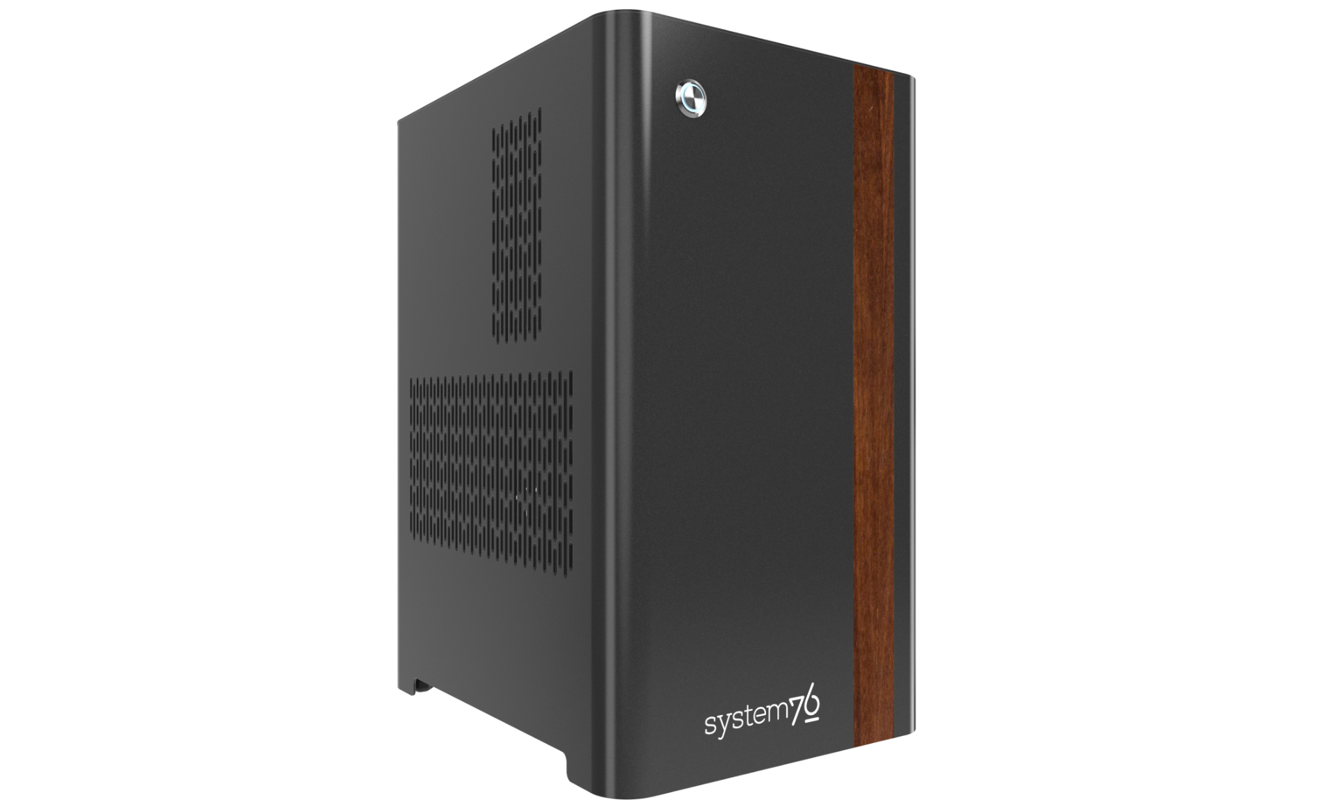
The System76 Thelio Astra is a desktop with the following specifications:
- Processor options
- Supports Ampere Altra and Altra Max family CPUs
- Motherboard options
- Revision 1.1: ASRock ALTRAD8UD-1L2T running System76 Firmware (non-open)
- Revision 1: ASRock ALTRAD8UD2-1L2Q running System76 Firmware (non-open)
- Daughterboard
- Thelio Io board running open-source firmware
- Version 2.3
- Thelio Io board running open-source firmware
- Graphics options
- Configured with up to one dedicated GPU
- Primary GPU slot:
- PCIe 4.0 x16
- Up to 5-slot height
- Primary GPU slot:
- GPU size:
- Internal clearance: 358.00mm
- Recommended maximum length: 348.00mm
- Tested with the following GPUs:
- NVIDIA RTX 6000 Ada
- 4x DisplayPort 1.4a
- NVIDIA RTX 4000 Ada
- 4x DisplayPort 1.4a
- NVIDIA RTX 2000 Ada
- 4x mini DisplayPort 1.4a
- NVIDIA GeForce RTX 4090
- 3x DisplayPort 1.4a
- 1x HDMI 2.1a
- NVIDIA RTX A400
- 4x Mini DisplayPort 1.4a
- NVIDIA RTX 6000 Ada
- 1x integrated VGA port (for system management)
- Configured with up to one dedicated GPU
- Expansion
- ALTRAD8UD-1L2T motherboard variant:
- 2x PCIe 4.0 x16 (top two slots)
- Runs at x8 bandwidth when using non-Max processor options
- 1x PCIe 4.0 x16 (primary GPU slot)
- 1x PCIe 4.0 x16 (bottom slot)
- CMOS battery mount may prevent long PCIe cards from fitting
- 2x PCIe 4.0 x16 (top two slots)
- ALTRAD8UD2-1L2Q motherboard variant:
- 2x PCIe 4.0 x16 (top two slots)
- Runs at x8 bandwidth when using non-Max processor options
- 1x PCIe 4.0 x16 (primary GPU slot)
- 1x PCIe 4.0 x16 (bottom slot)
- 2x PCIe 4.0 x16 (top two slots)
- ALTRAD8UD-1L2T motherboard variant:
- Memory
- Up to 512GB (8x64GB) octa-channel DDR4 RDIMM/LRDIMMs @ 3200 MHz
- Tested with the following RAM modules (may ship with other tested modules):
- Samsung M393A8G40AB2-CWE (64GB/stick)
- Samsung M393A4K40DB3-CWE (32GB/stick)
- Networking
- ALTRAD8UD-1L2T motherboard variant:
- 2x 10-Gigabit Ethernet (Intel X550)
- 1x 2.5-Gigabit Ethernet (Intel i210)
- 1x 1-Gigabit Ethernet (Realtek RTL8211E)
- Dedicated IPMI port
- ALTRAD8UD2-1L2Q motherboard variant:
- 2x 25-Gigabit SFP28 (Broadcom BCM57414)
- 1x or 2x 10-Gigabit Ethernet (RJ-45) transceivers are available as build options.
- 1x 2.5-Gigabit Ethernet (Intel i210)
- 1x 1-Gigabit Ethernet (Realtek RTL8211E)
- Dedicated IPMI port
- 2x 25-Gigabit SFP28 (Broadcom BCM57414)
- ALTRAD8UD-1L2T motherboard variant:
- Power
- C13 power cord
- 850W PSU
- 80+ Gold Efficiency
- Tested with the following PSU models (may ship with other tested models):
- Storage
- ALTRAD8UD-1L2T motherboard variant:
- 2x M.2 (PCIe NVMe Gen 4) SSDs
- Additional SSDs offered with PCIe adapter card
- ALTRAD8UD2-1L2Q motherboard variant:
- 1x M.2 (PCIe NVMe Gen 4) SSD
- Additional SSDs offered with PCIe adapter card
- ALTRAD8UD-1L2T motherboard variant:
- USB
- Back ports:
- 4x USB 3.2 Gen 1 (Type-A)
- Back ports:
- Dimensions
- 43.8cm × 24.7cm × 37.2cm
Thelio Astra (External Overview)
Back overview:

SFP Port Information:
- When ordering Thelio Astra revision A1 (with the
ALTRAD8UD2-1L2Qmotherboard), options for one or two 10GbE RJ-45 transceivers preinstalled into the 25GbE SFP port(s) are offered.- No transceivers are installed in the photo above.
- Thelio Astra revision A1.1 (with the
ALTRAD8UD-1L2Tmotherboard) includes two built-in 10GbE RJ-45 ports instead of SFP ports.
Unit Identification (UID) Button Guide:
- Pressing the button toggles the blue identification light on and off.
- The light can also be toggled remotely using the baseboard management controller (BMC).
- Holding the button for more than 4 seconds resets the baseboard management controller (BMC) to default settings.
- After resetting the BMC using this method, it may be necessary to power cycle the Thelio Astra before the BMC becomes reachable again.
PCIe Slot Information:
- The top two PCIe slots run at x16 bandwidth with Altra Max processor options, and run at x8 bandwidth with Altra (non-Max) processor options.
Power Switch Guide:
- 1: On
- 0: Off
Front/side overview:
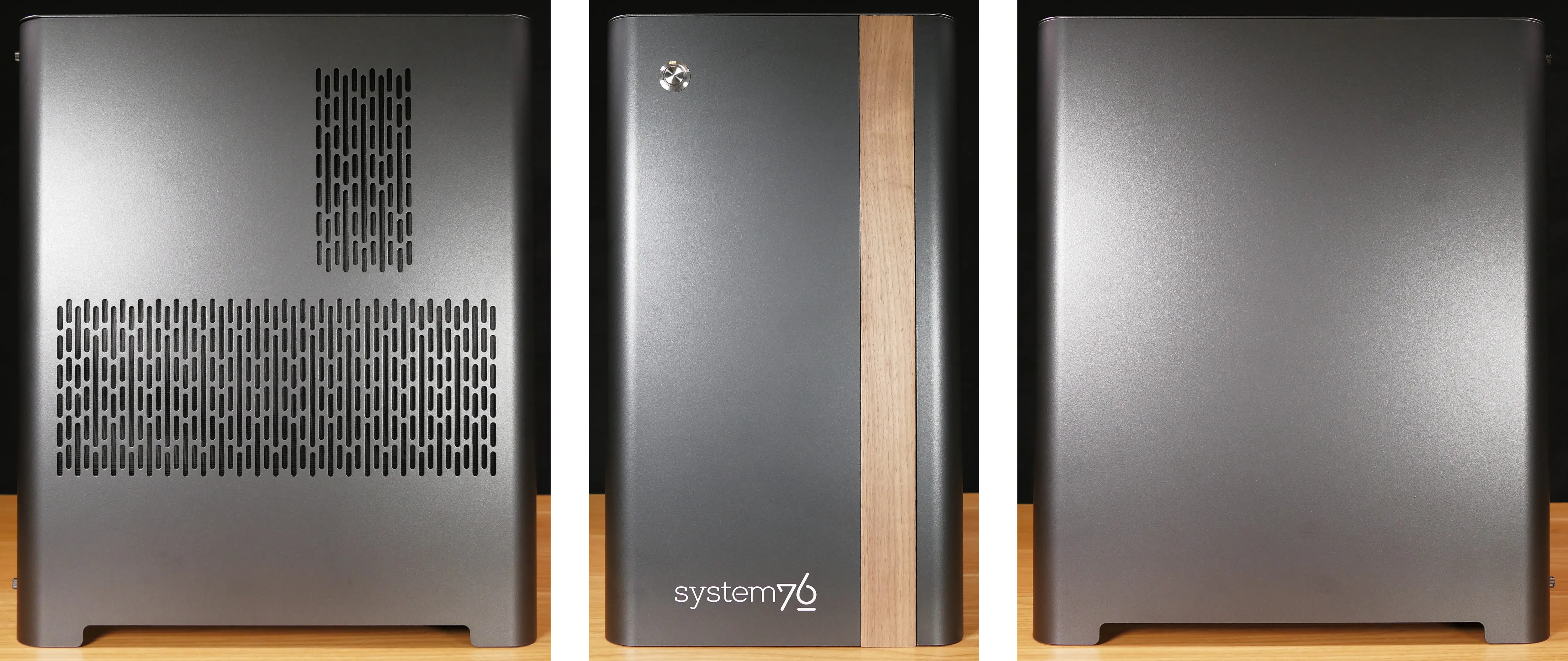
Top/bottom overview:
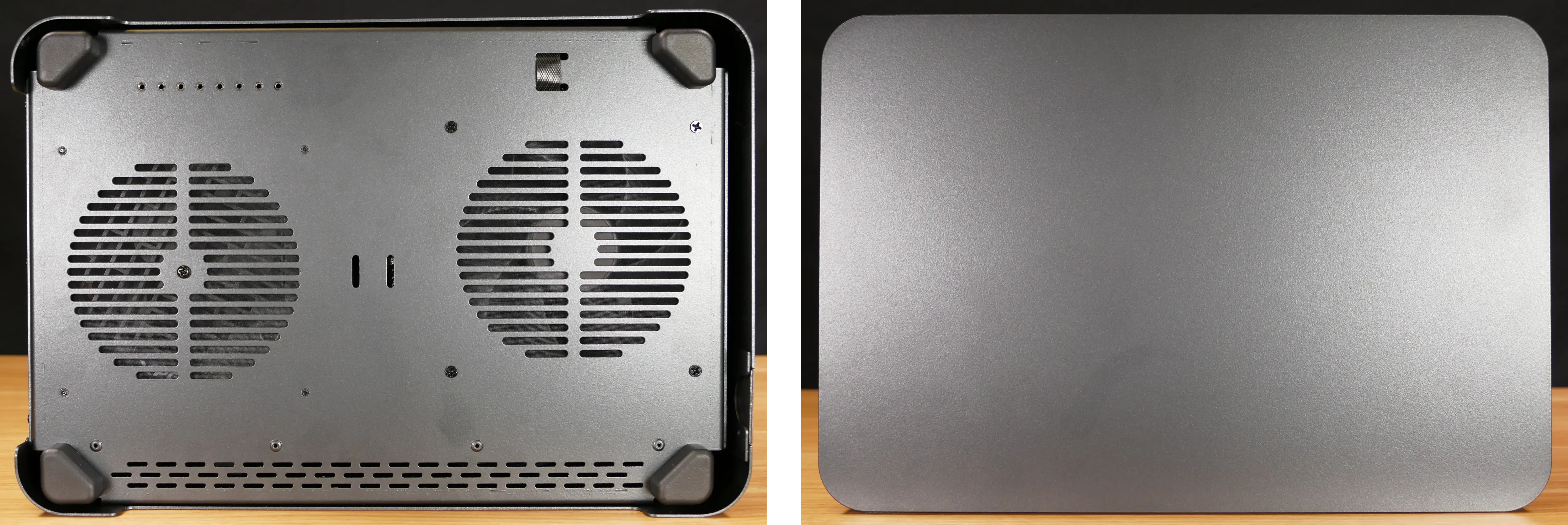
Thelio Mira (Internal Overview)
Left side overview:
Chassis components:
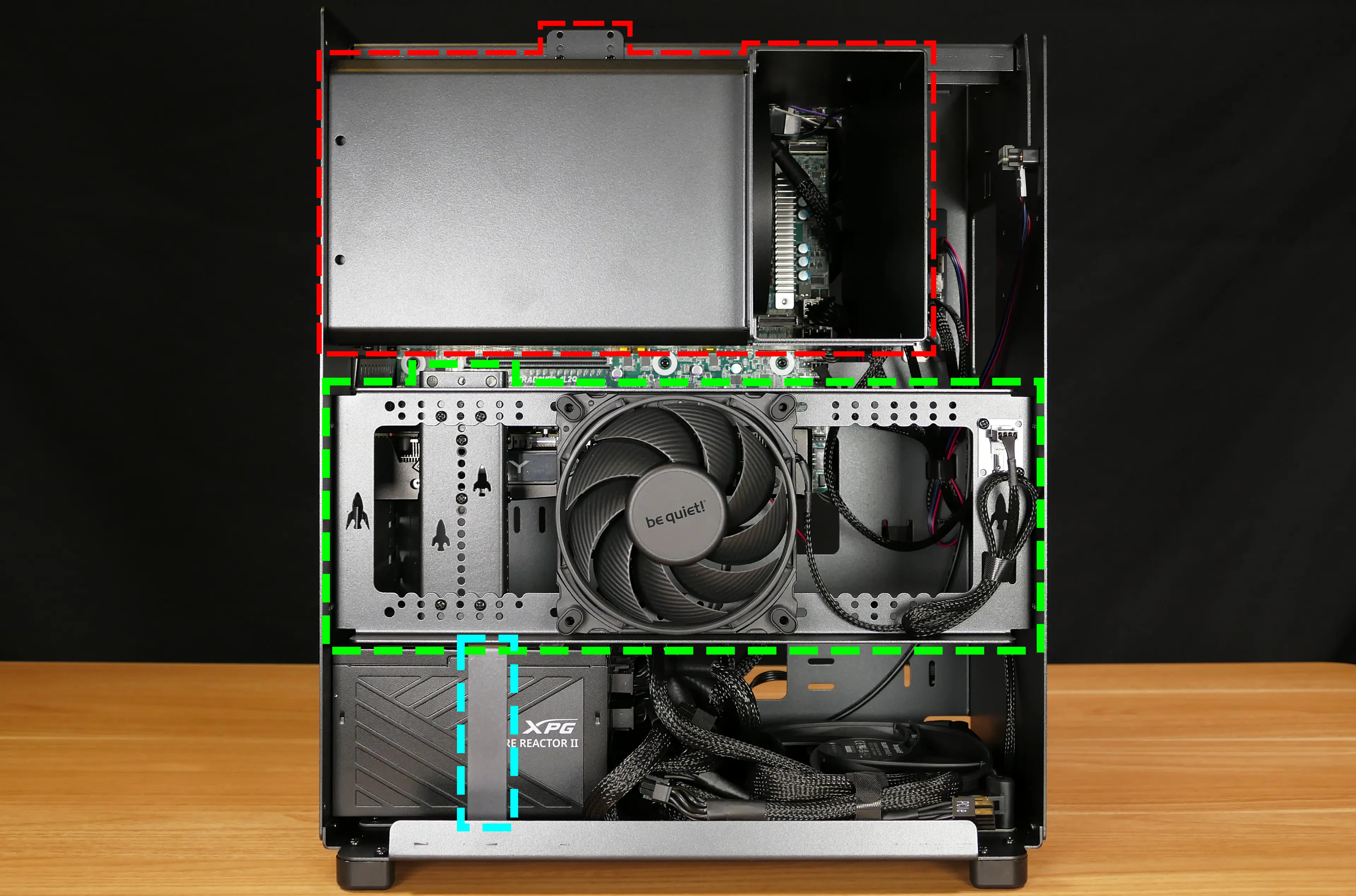
- CPU duct is highlighted in red
- Side brace is highlighted in green
- PSU bracket is highlighted in cyan
Electronic components:
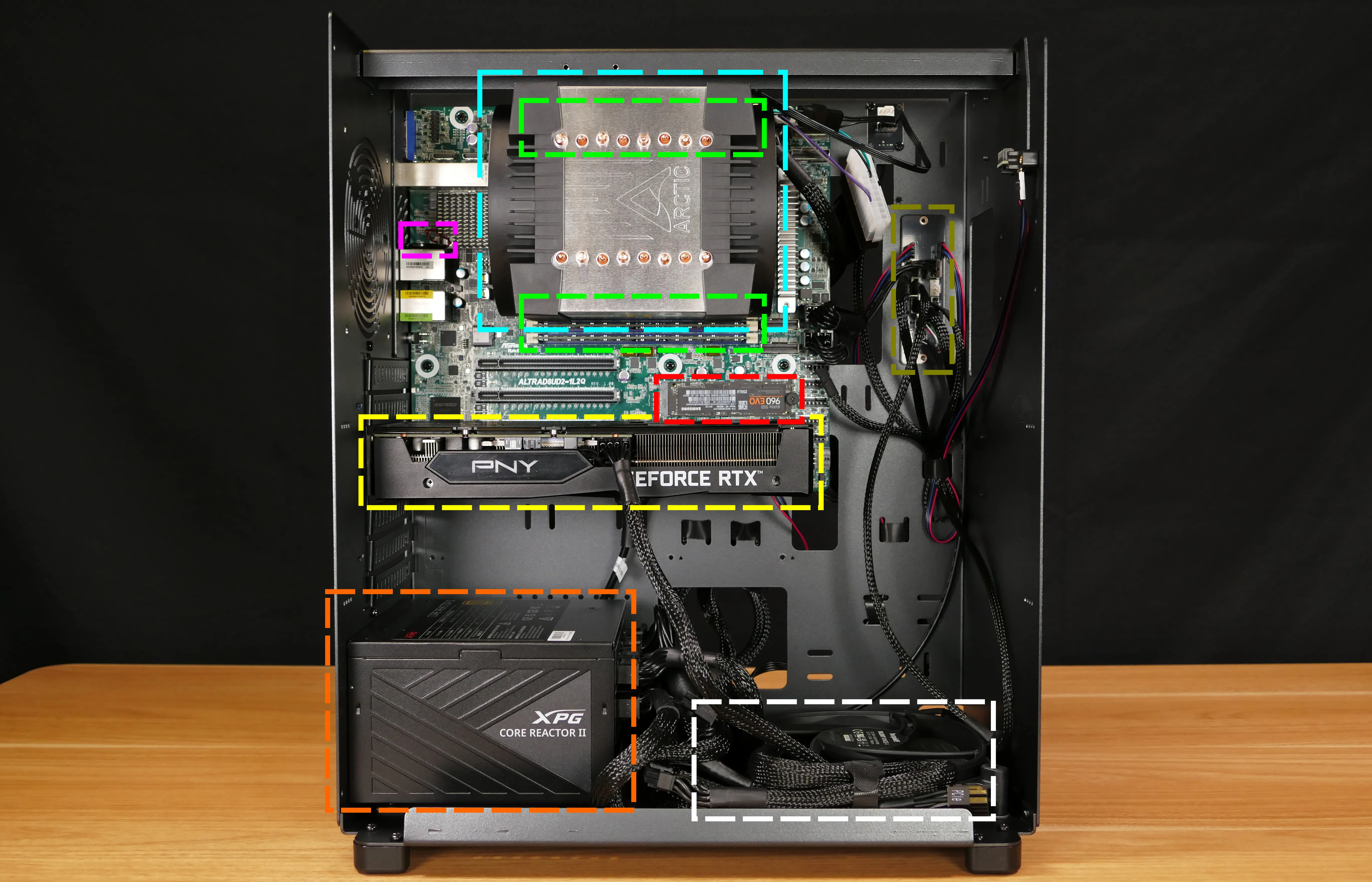
- CPU heatsink is highlighted in cyan
- RAM slots are highlighted in green
- CMOS battery is highlighted in pink
- Thelio Io daughterboard is highlighted in olive
- M.2 slot is highlighted in red
- GPU is highlighted in yellow
- Power supply is highlighted in orange
- Bottom case fan is highlighted in white
Right side overview:
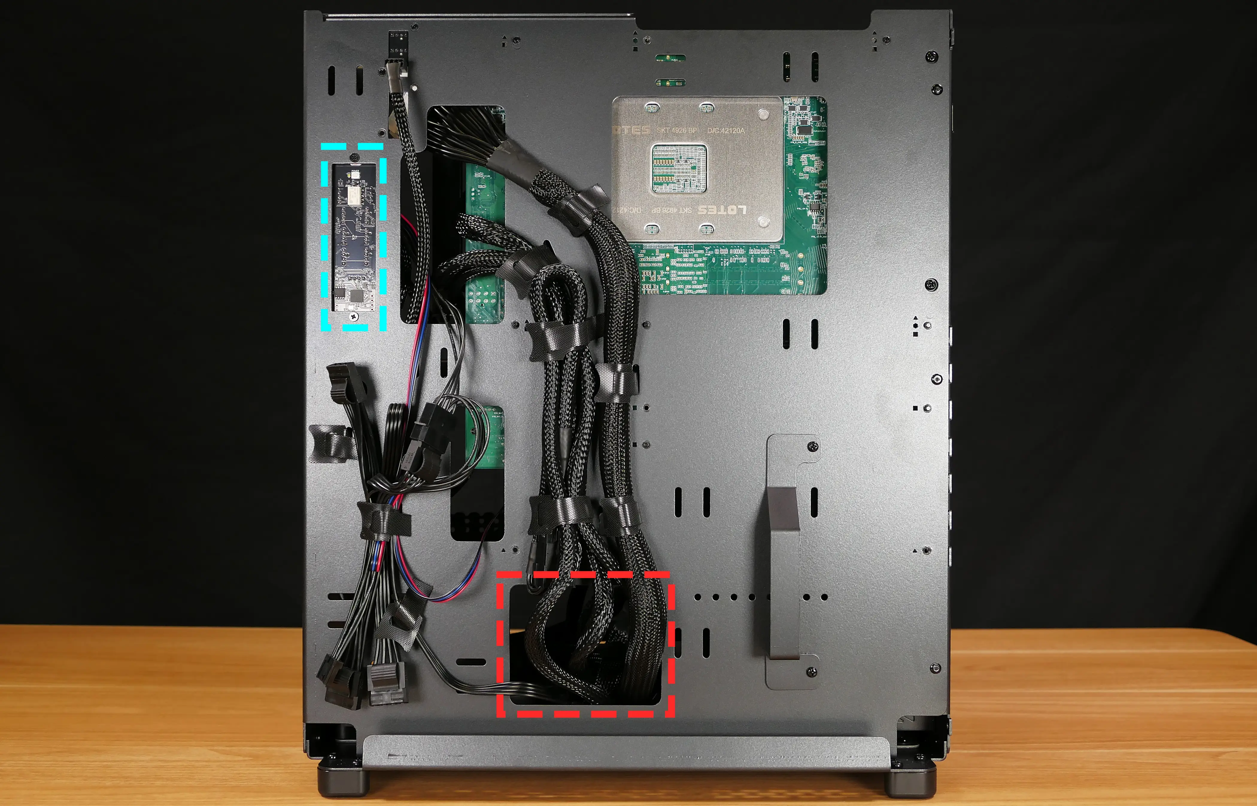
- Back of Thelio Io board is highlighted in cyan
- Internal power button is on the Thelio Io board
- Power supply access cutout is highlighted in red
Front side overview:
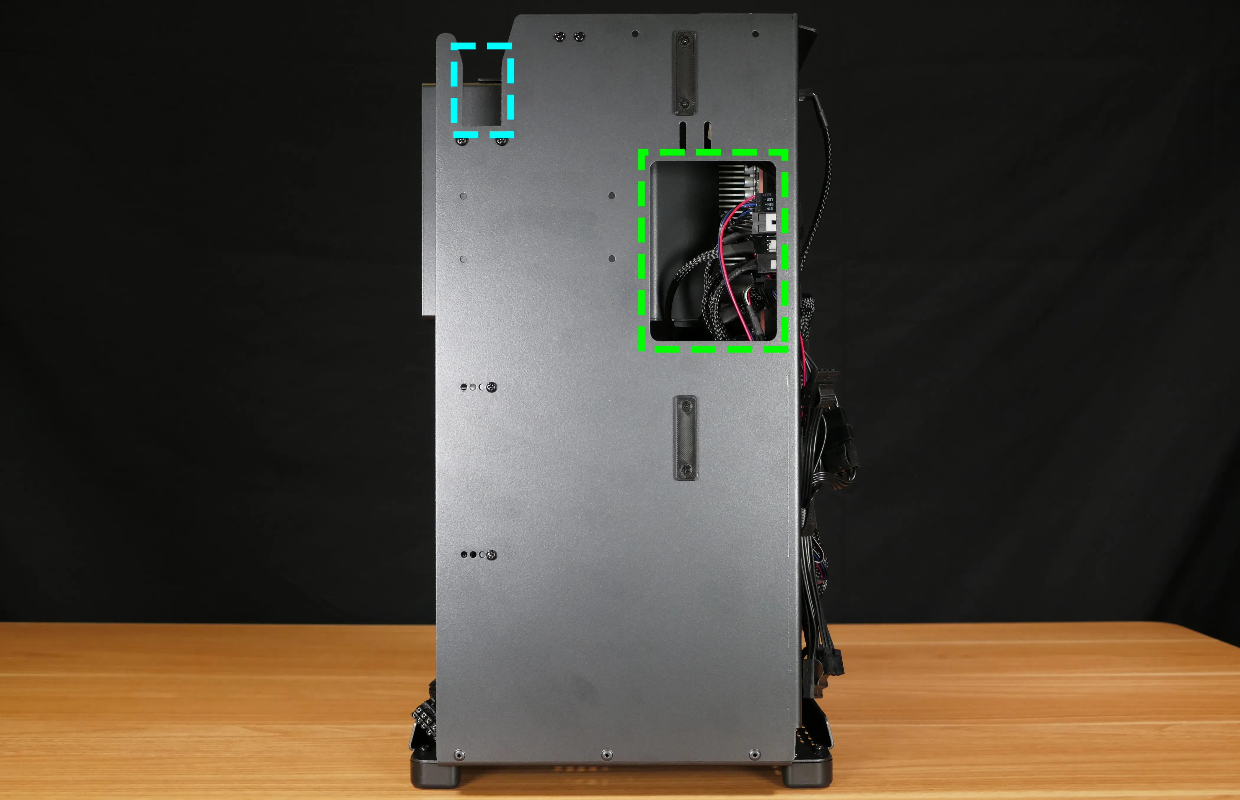
- Power button receptacle cutout is highlighted in cyan
- Thelio Io connector access cutout is highlighted in green
Top overview:
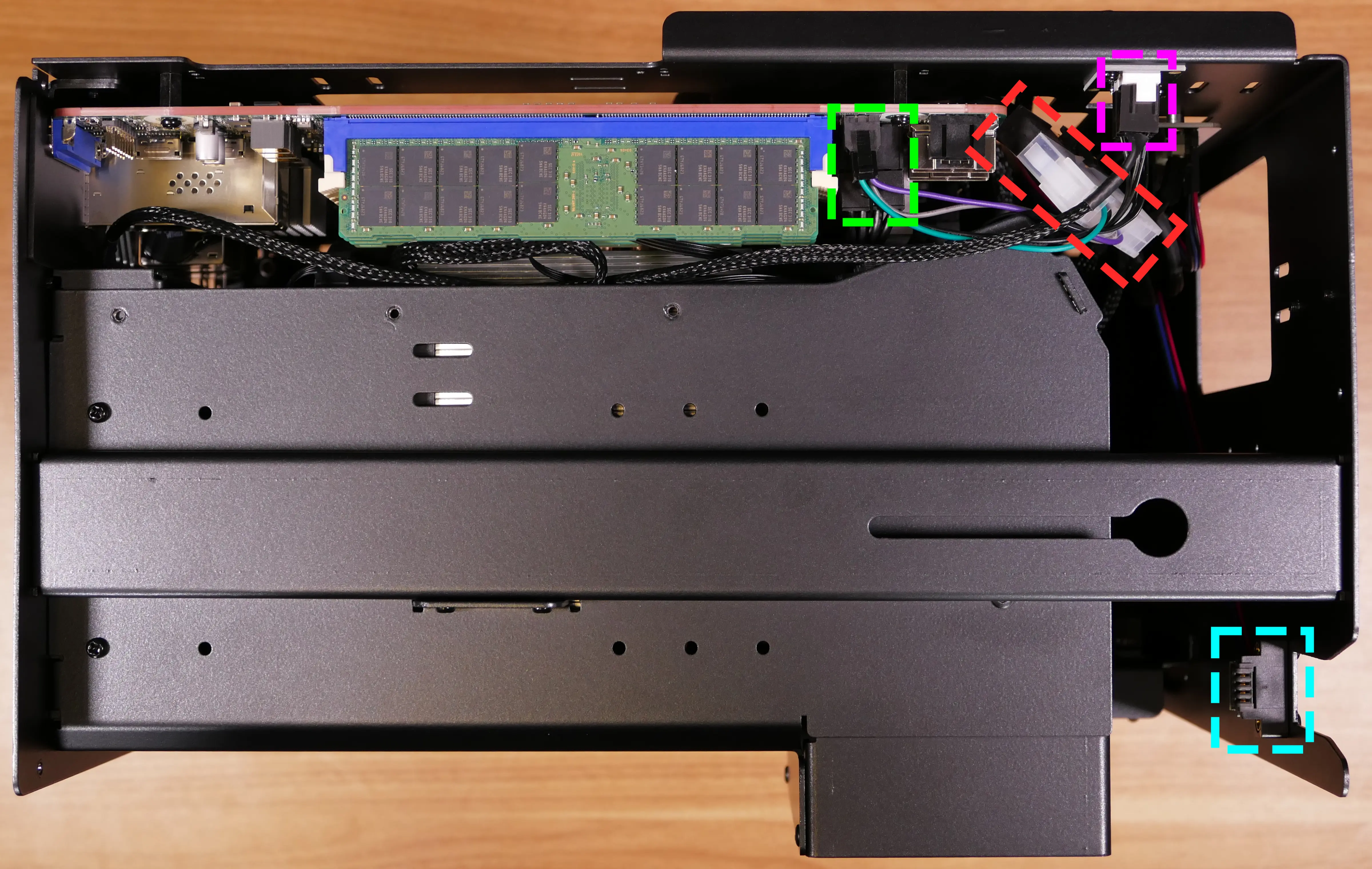
- CPU & motherboard power connectors are highlighted in green
- Motherboard power connector is on top, CPU power connector is below
- Connect to power supply
- Motherboard power adapter is highlighted in red
- Black side connects to power supply
- White side connects to motherboard
- CPU fan splitter is highlighted in pink
- Connects to CPU fans and Thelio Io board
- Power button receptacle is highlighted in cyan
- Connects to Thelio Io board
See the repairs page for detailed information about installing or replacing components.
Thelio Astra (Parts & Repairs)
Many components in your Thelio Astra can be upgraded or replaced as necessary. This page uses photos of the the A1-N1 revision, which indicates:
- A1: The first Ampere-compatible motherboard used in Thelio Astra (
ALTRAD8UD2-1L2Q).- Units marked A1.1 include the
ALTRAD8UD-1L2Tmotherboard instead.
- Units marked A1.1 include the
- N1: The first chassis revision of the Thelio Astra.
- The Thelio Astra chassis is based on the nebula40 chassis (revision 3), but lacks top I/O and 2.5" drive mounts.
Minor case details may vary based on the production date of the unit, but screw counts, general component locations, and other details should remain the same unless otherwise noted.
Power the machine off, switch off the power supply, and unplug all peripherals before working with any internal components. Then, follow these step-by-step guides for instructions:
- Replacing the front accent strip
- Removing the top case
- Removing the side brace
- Replacing the bottom case fan
- Removing the CPU duct
- Replacing the RAM
- Replacing the GPU
- Replacing the CMOS battery
- Replacing the M.2 drives
- Replacing the CPU fans
- Replacing the CPU cooler/thermal paste and CPU
- Replacing the power supply
- Replacing the Thelio Io board
- Troubleshooting the power button
Replacing the front accent strip:
Thelio Astra includes a customizable accent panel on the front of the case, which can be swapped to change the case's look and feel. The instructions for swapping the accent are also available in video form.
Tools required: None
Time estimate: 30 seconds
Difficulty: Easy ●
Steps to replace the front accent strip:
- Place the Thelio on the edge of the desk so the front side is hanging off of the desk.
- The Thelio can alternatively be lifted or tilted so the front of the computer is hovering above the desk.
- Slide the accent strip down to unlock it.
- The accent can be gripped at the bottom edge.
- Pull the accent strip off of the case, starting with the bottom edge.
- Place the new accent strip onto the front of the case and slide it up to lock it into place.

Removing the top case:
The top case can be removed to access the internal components.
Tools required: Cross-head (Phillips) screwdriver (optional)
Time estimate: 2 minutes
Difficulty: Easy ●
Steps to remove the top case:
- Remove the four outer screws holding the top case onto the machine.

- Slide the top case up and off of the machine.
Removing the side brace:
The side brace provides a mounting point for the GPU brace fingers, which help keep GPUs or other PCI Express cards in place during shipping. It also provides mounting points for up to two 120mm fans; one 120mm fan is offered as an optional add-on during factory configuration.
The GPU brace fingers are only required during shipping. The system can be run without this part if it does not fit an upgraded GPU.
Part numbers:
- The optional side fan is a 120mm Be Quiet! Silent Wings 4.
- Model number:
BQ SIW4-12025-MF-PWM
- Model number:
Tools required: Cross-head (Phillips) screwdriver
Time estimate: 15 minutes
Difficulty: Easy ●
Steps to remove the side brace:
- Follow the steps above to remove the top case.
- Unscrew the four screws holding the side bracket in place (two on the front of the case, two on the back).
- Take note of which screw holes the side brace is screwed into, which varies by GPU. In the below photos, the innermost set of screw holes is used.
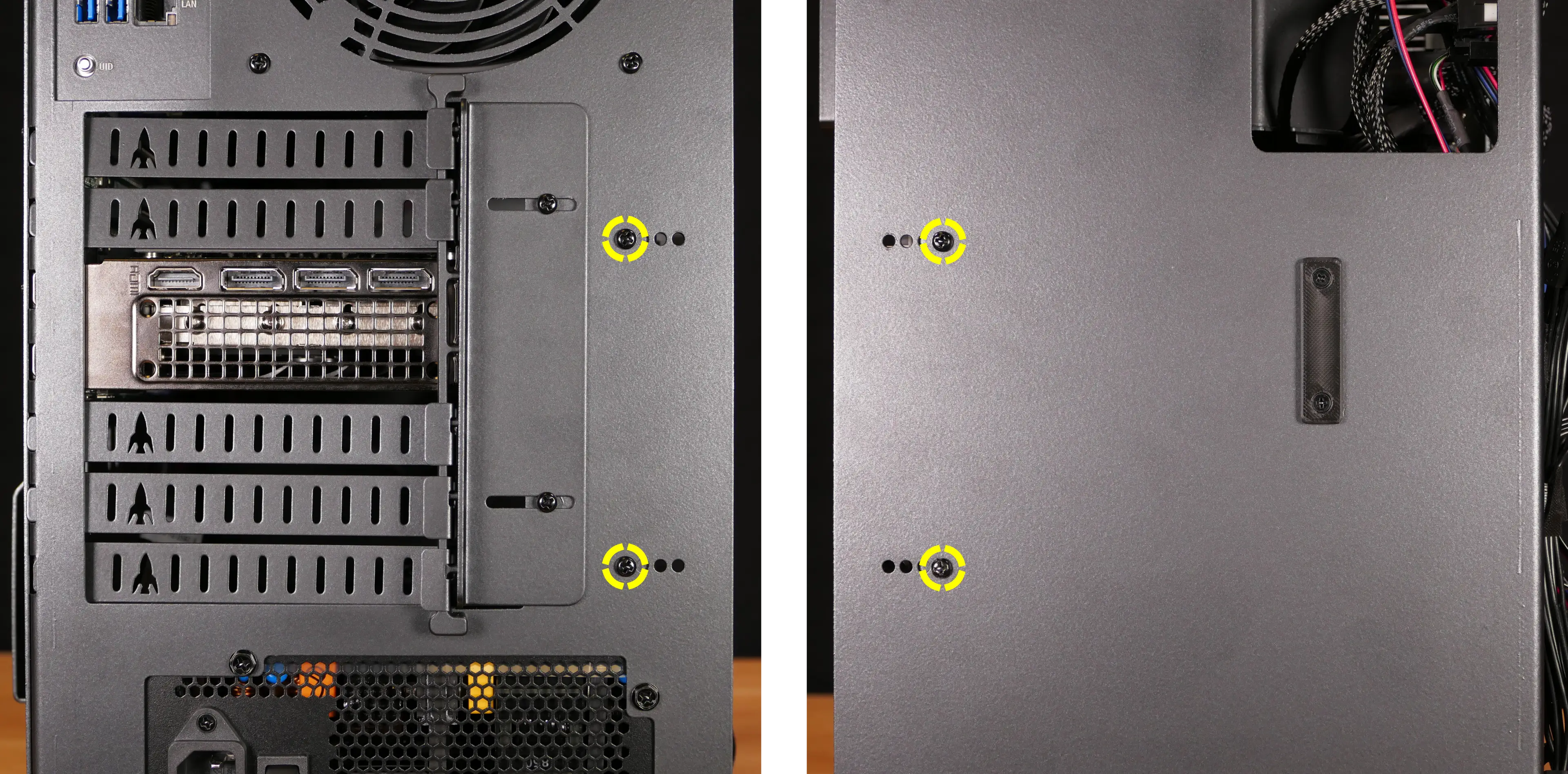
- Pull the side brace out of the chassis. Unplug the side fan connector from the splitter board on the right side, if connected.
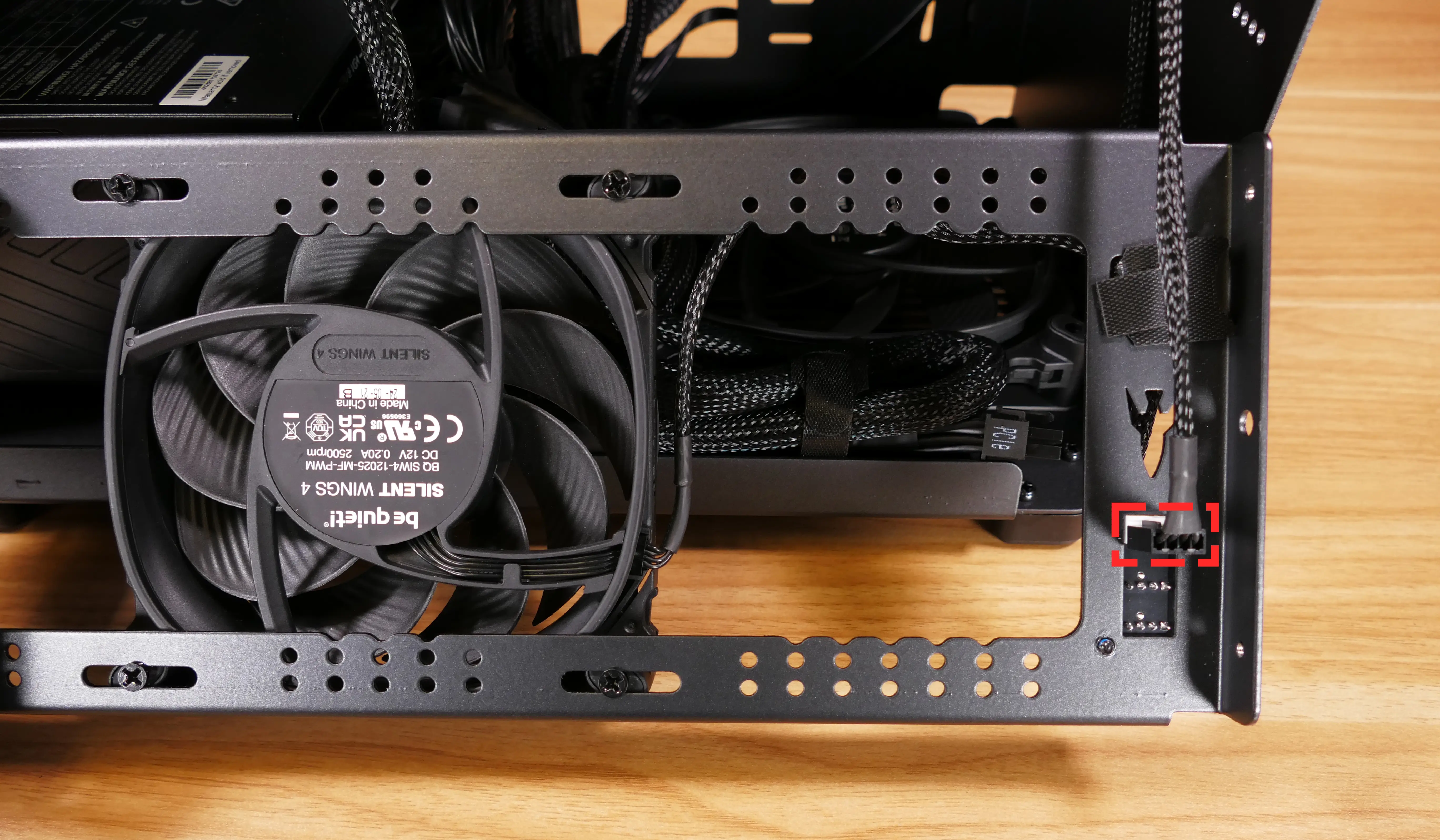
Steps to adjust the GPU brace fingers:
- Follow the steps above to remove the top case and remove the side brace.
- To adjust the GPU brace fingers' horizontal position, unscrew the four corner screws (highlighted green below), move the GPU brace fingers' mounting bar, and reattach it in the desired position.
- If any vertical alignment screws overlap the side brace, they will also need to be removed.
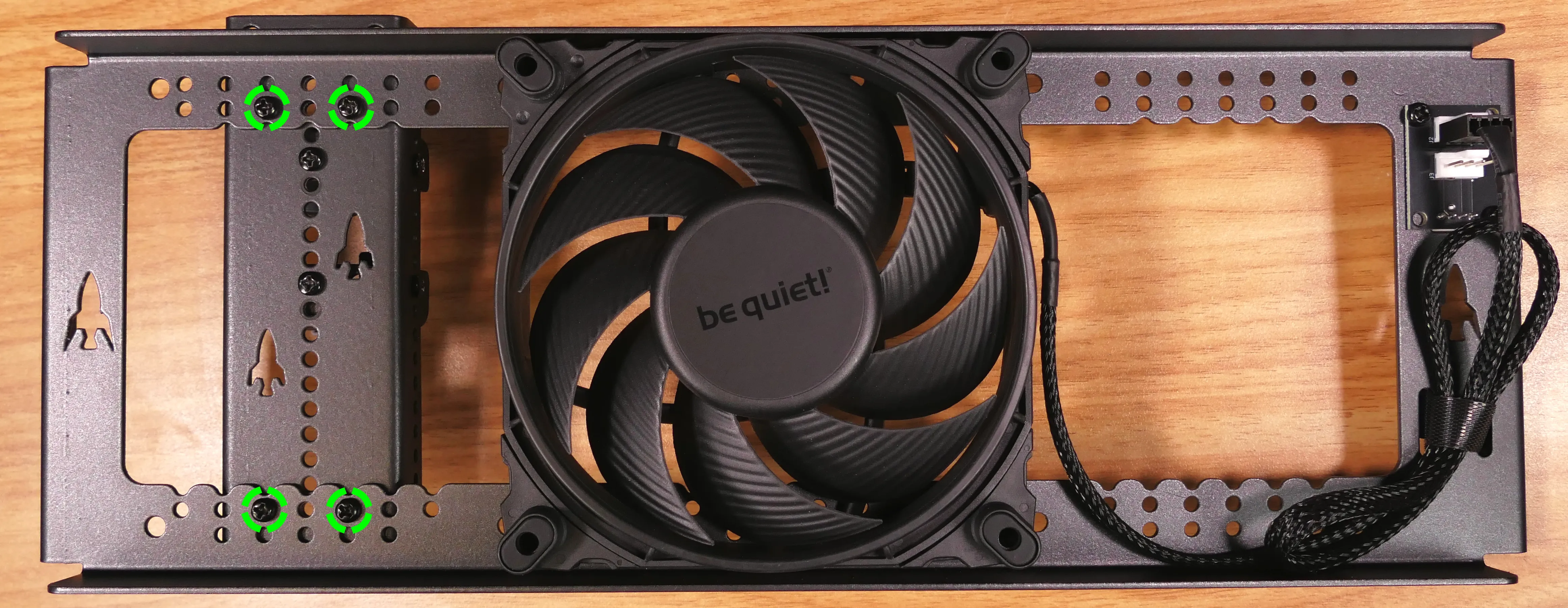
- To adjust a GPU brace finger's vertical position, unscrew the three vertical adjustment screws (per finger), move the GPU brace finger, and reattach it in the desired position.
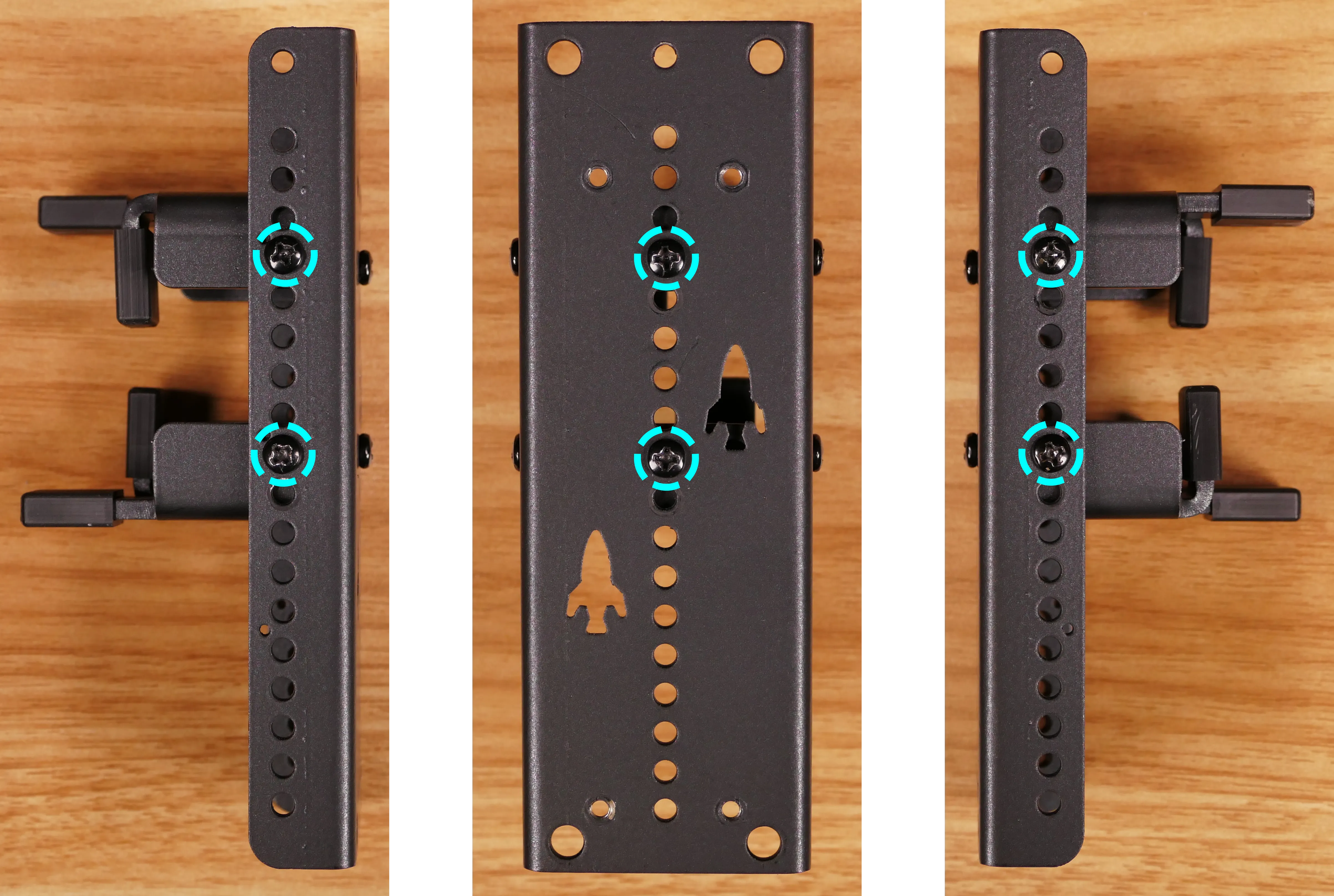
Steps to replace the side GPU fan:
- Follow the steps above to remove the top case and remove the side brace.
- Unplug the GPU fan from the splitter board on the side brace and free its cable from the velcro strap.
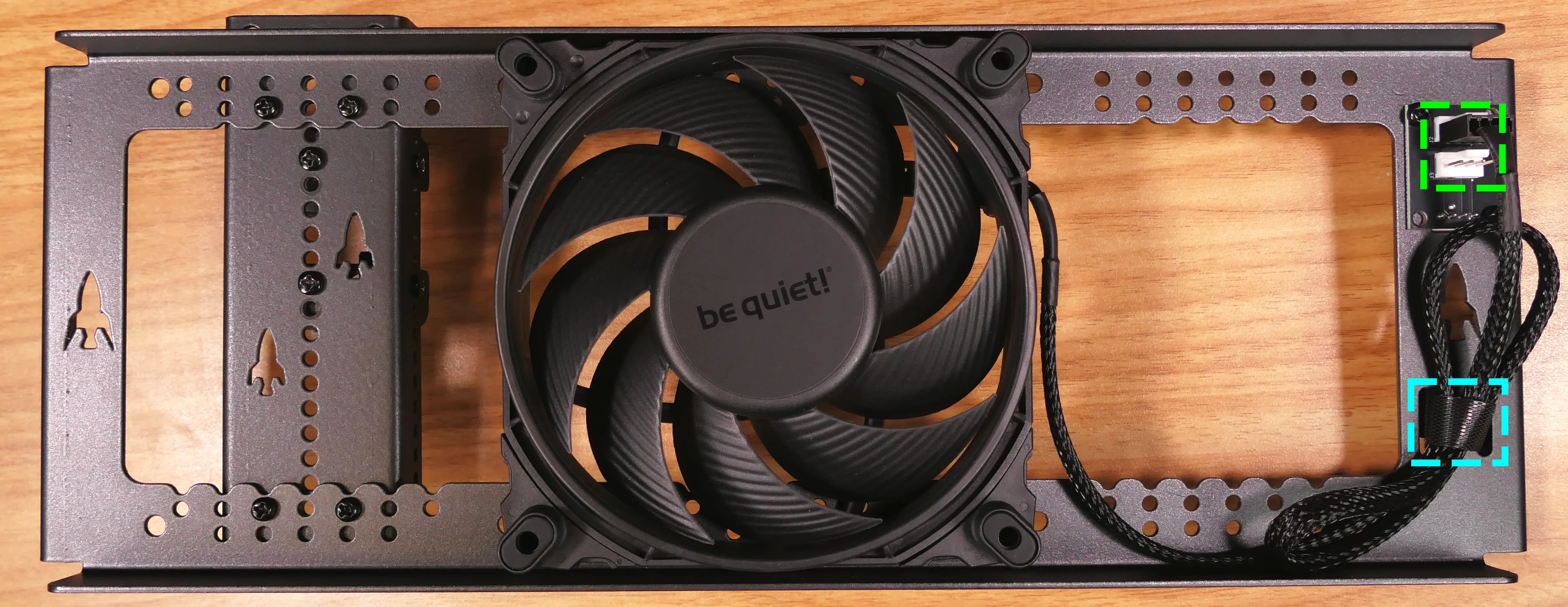
- Remove the four screws holding the side GPU fan in place.
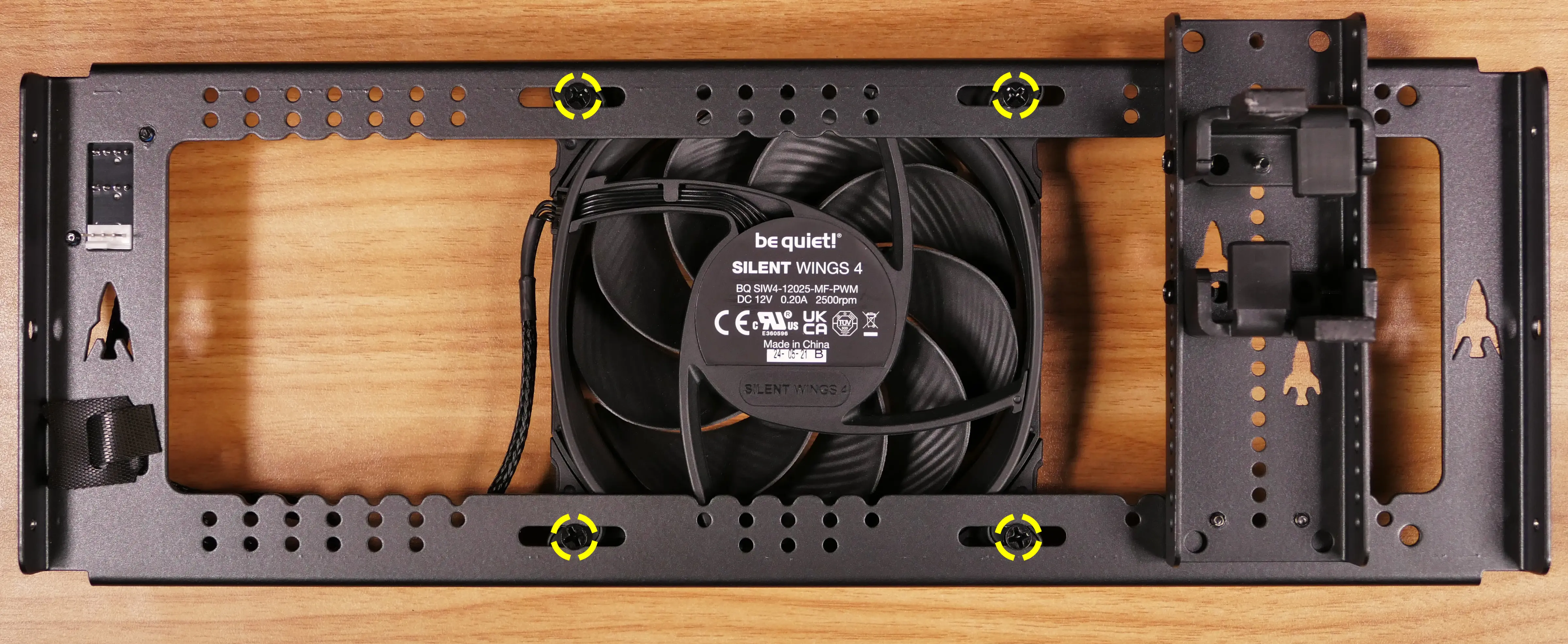
- Screw the new fan into the side brace, plug it into the splitter board, and secure its cable with the velcro strap.
Replacing the bottom case fan:
Thelio Astra A1-N1 has one case-mounted intake fan on the bottom of the chassis.
Part numbers:
- The bottom case fan is a 140mm Be Quiet! Silent Wings 4.
- Model number:
BQ SIW4-14025-MF-PWM
- Model number:
Tools required: Cross-head (Phillips) screwdriver
Time estimate: 20 minutes
Difficulty: Medium ●
Steps to replace the bottom case fan:
- Follow the steps above to remove the top case.
- The side brace can optionally be removed to provide easier access to the fan and its cabling.
- Unplug the fan's cable from the Thelio Io daughterboard.
- The bottom case fan plugs into the
INTAKE FAN/FANOUT2port on the Thelio Io board. - When viewed from the access cutout on the front of the case, this connector is the lowest one with a white receptacle.
- The bottom case fan plugs into the
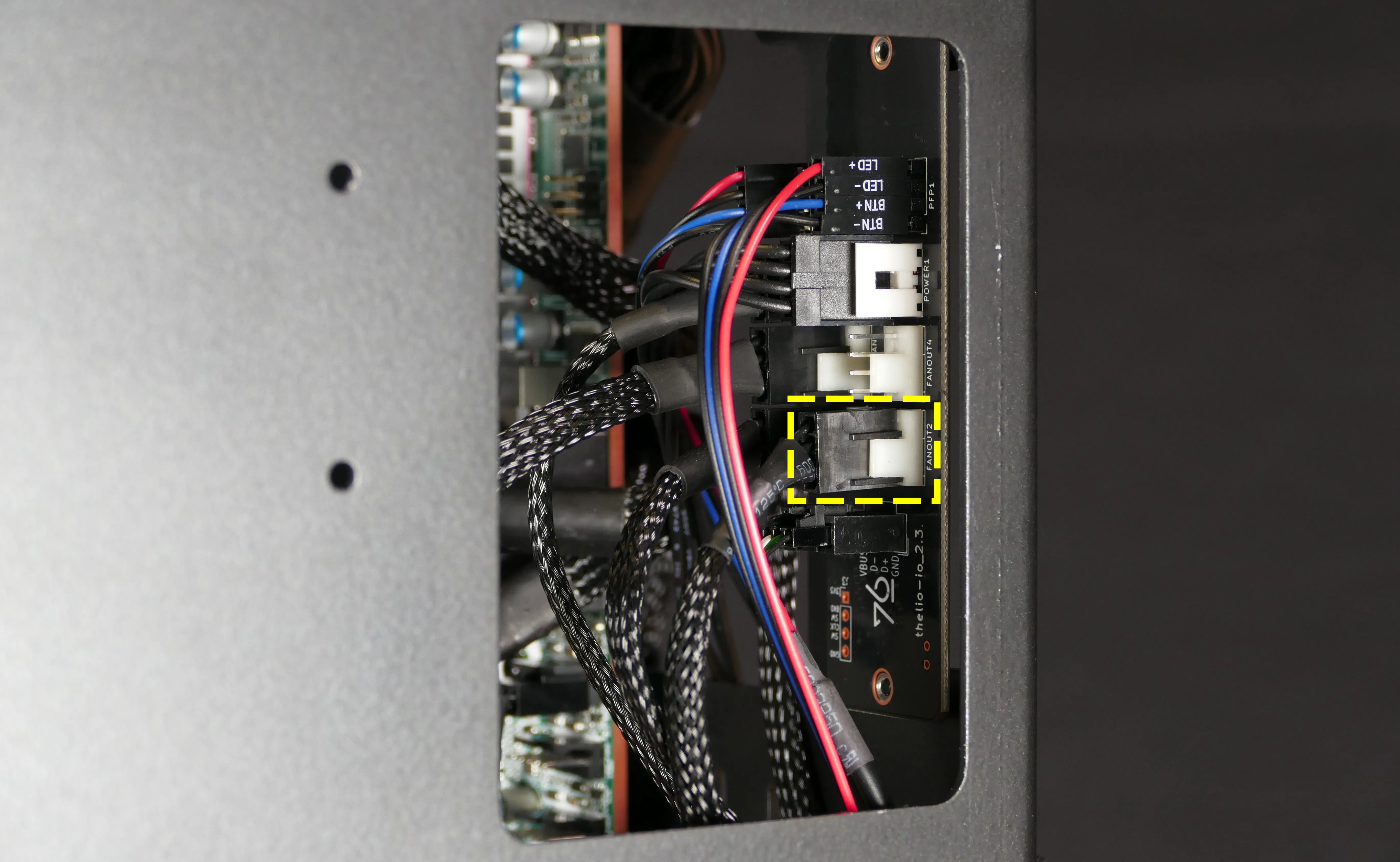
- Unscrew the four fan screws from the bottom of the machine.
- To avoid damaging other components, place the machine on its front side when working with the bottom surface.
- A soft surface such as a towel can optionally be used to protect the work surface and the machine.

- Remove the old fan from the case.
- When installing the fan, mount the components in the following order:
- Chassis
- Dust filter
- Acrylic spacer
- Fan
- The new fan's cable should be oriented towards the front-right corner of the case.
- The cable runs along the inner corner of the case, passing through the velcro strap closest to the Thelio Io board.
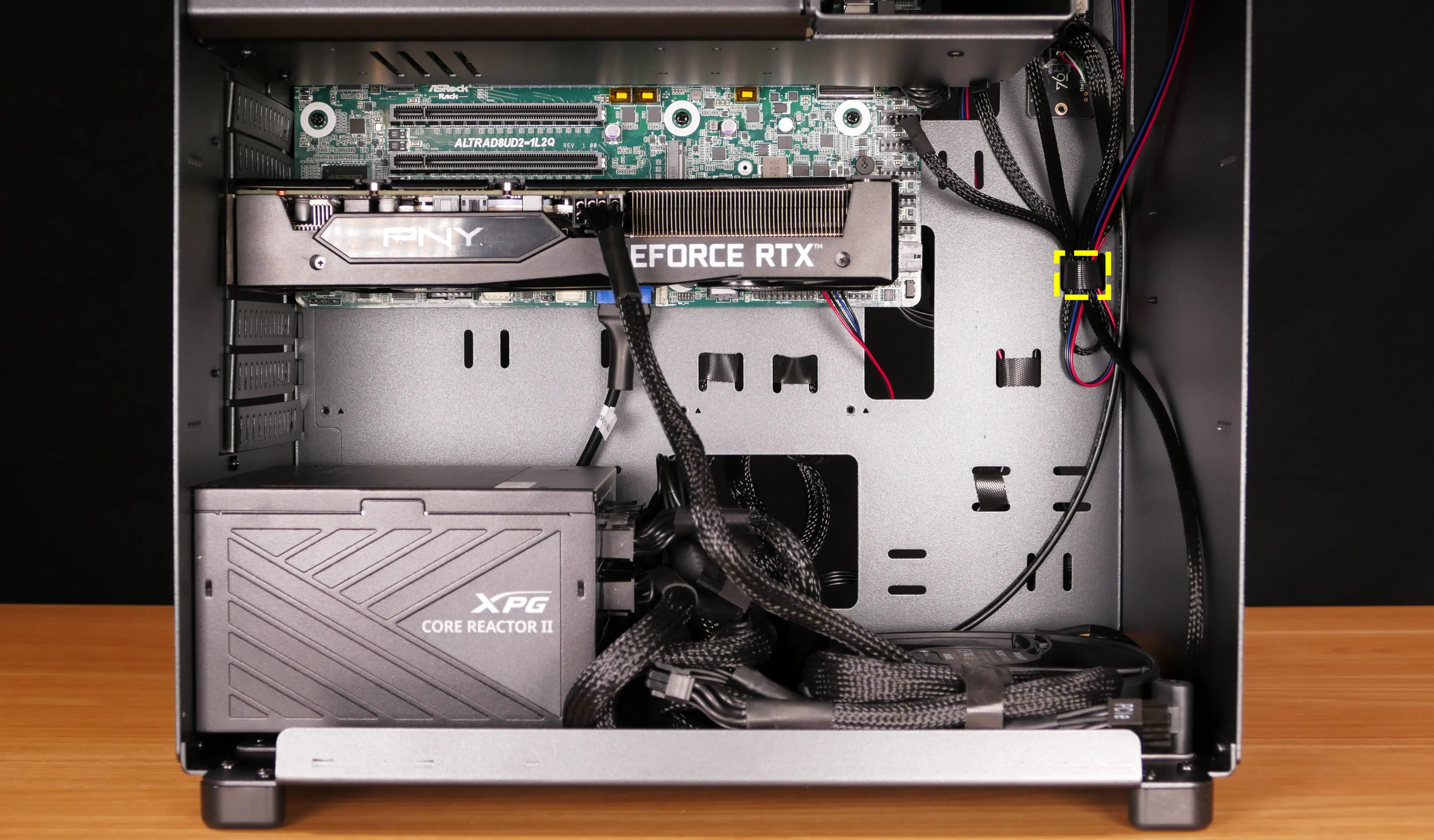
Removing the CPU duct:
The CPU duct guides airflow through the CPU cooler. It covers the CPU and partially obstructs the RAM slots and top PCIe slot.
Tools required: Cross-head (Phillips) screwdriver
Time estimate: 7 minutes
Difficulty: Easy ●
Steps to remove the CPU duct:
- Follow the steps above to remove the top case.
- Unplug the braided fan connector (highlighted red below) from the top splitter board in the front corner of the machine.
- The splitter board provides the same signal to both ports, so it doesn't matter which port each cable is plugged into. In the below photo, the braided cable is plugged into the top port (
J2).
- The splitter board provides the same signal to both ports, so it doesn't matter which port each cable is plugged into. In the below photo, the braided cable is plugged into the top port (
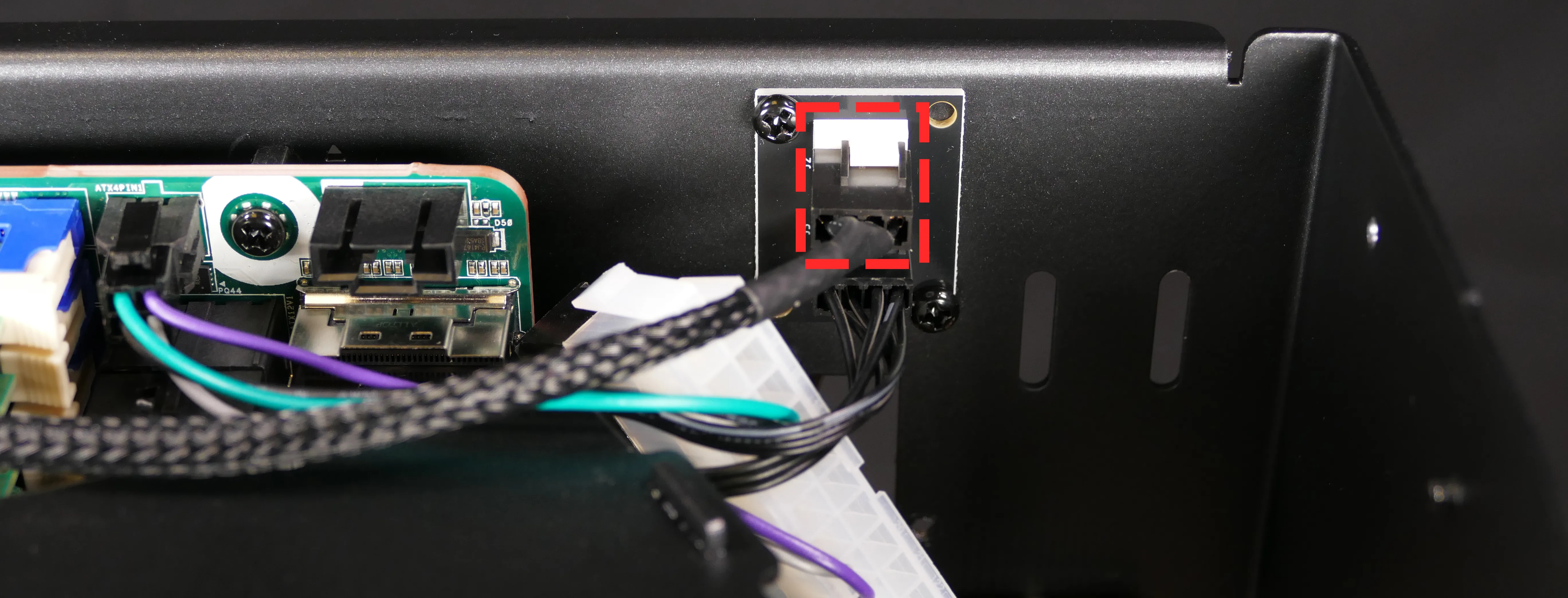
- Unscrew the four back screws and two top crossbar screws holding the CPU duct in place.


- Pull the CPU duct away from the machine.
Replacing the RAM:
Thelio Astra A1-N1 supports up to 512GB (8x64GB) of RAM. The RAM sticks are ECC DDR4 RDIMMs/LRDIMMs running at a speed of 3200 MHz.
If you've purchased new RAM, need to replace your RAM, or are reseating your RAM, follow these steps.
Tools required: Cross-head (Phillips) screwdriver
Time estimate: 15 minutes
Difficulty: Medium ●
Steps to replace the RAM:
- Follow the steps above to remove the top case and remove the CPU duct.
- Removing the CPU cooler is not physically required, but can optionally be done for easier access to the inner RAM slots. Replacing the thermal paste is strongly recommended if the CPU cooler is removed. In the below photo, the CPU cooler has been removed for greater visibility.
- If installing/removing RAM in any of the top RAM slots, unplug the 8-pin CPU power cable (labeled
ATX12V1to the right of the port), highlighted red below.

- To remove an existing RAM stick, flip the left and right latches away from the stick, then pull the stick out of the slot.
- Make sure the tabs on the left and right of the slot are open (pulled away from the slot), then insert the new RAM (or re-seat the existing RAM) into the slot.
- The RAM stick will only fit in one direction. The larger group of pins goes on the left.
- Use the following guide for placement of the RAM sticks:
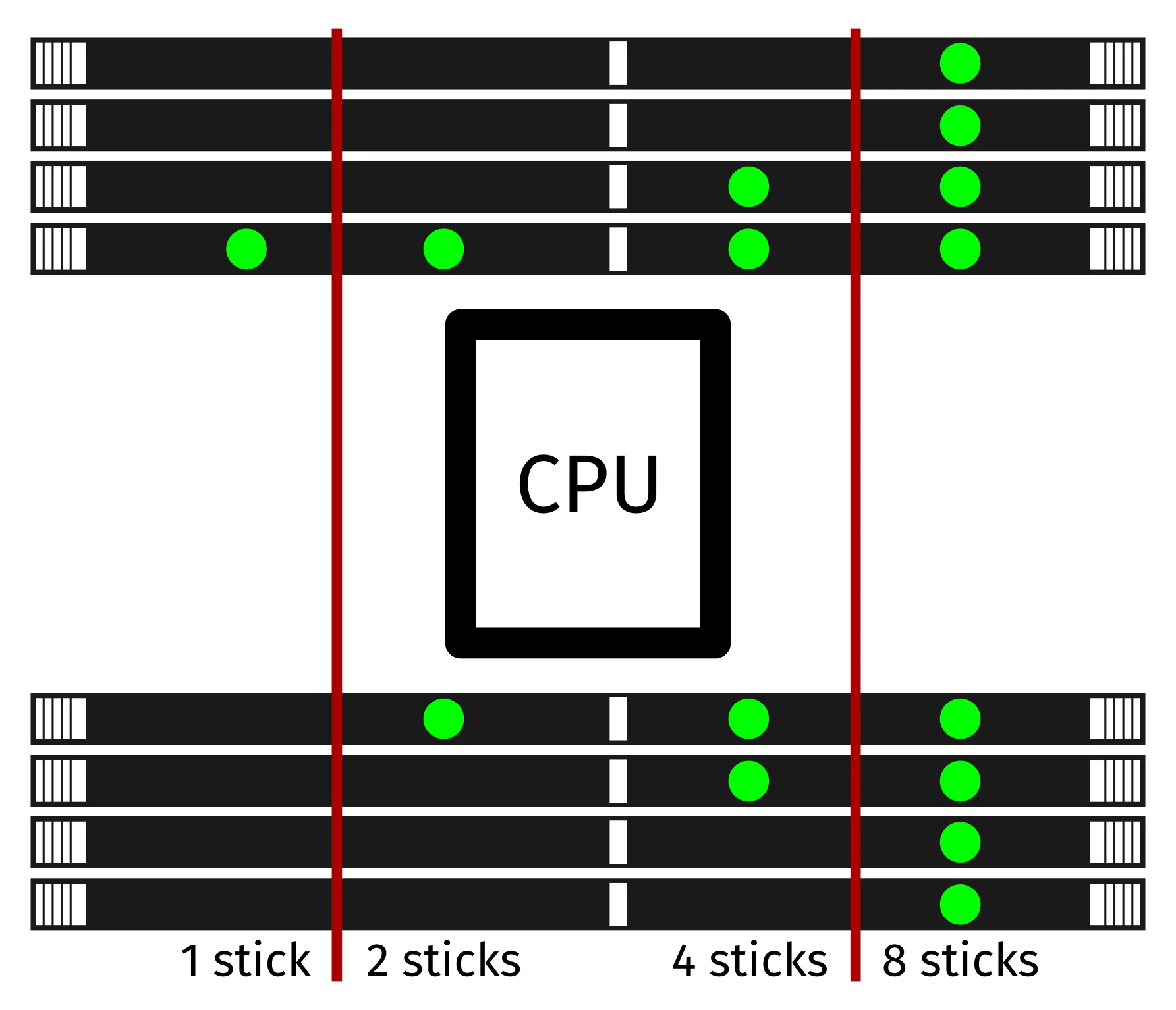
- Replace the CPU cooler (if necessary), CPU duct, and top case.
Replacing the GPU:
Thelio Astra ships with one dedicated GPU in the PCIe 4.0 x16 slot third from the top. GPUs greater than one slot tall will obstruct the lowest PCIe slot.
Depending on your motherboard and firmware version, the boot splash screen may not show up if the GPU is installed in either of the top two PCIe slots. For this reason, and for optimal thermal efficiency, it's recommended to reserve the top two slots for non-GPU PCIe accessories.
Tools required: Cross-head (Phillips) screwdriver
Time estimate: 15 minutes
Difficulty: Medium ●
Steps to replace the GPU:
- Follow the steps above to remove the top case and remove the side brace.
- If you're removing a GPU, unplug the GPU power cable from the right side of the card. Hold down the latch on the connector while unplugging the cable.
- Thelio Astra includes both classic 6+2-pin and 12VHPWR 16-pin GPU power cables. If you're changing GPUs and switching from one type of cable to the other, you may need to free the new cable from the velcro straps at the bottom of the chassis, then secure the old cable out of the way using the velcro straps.
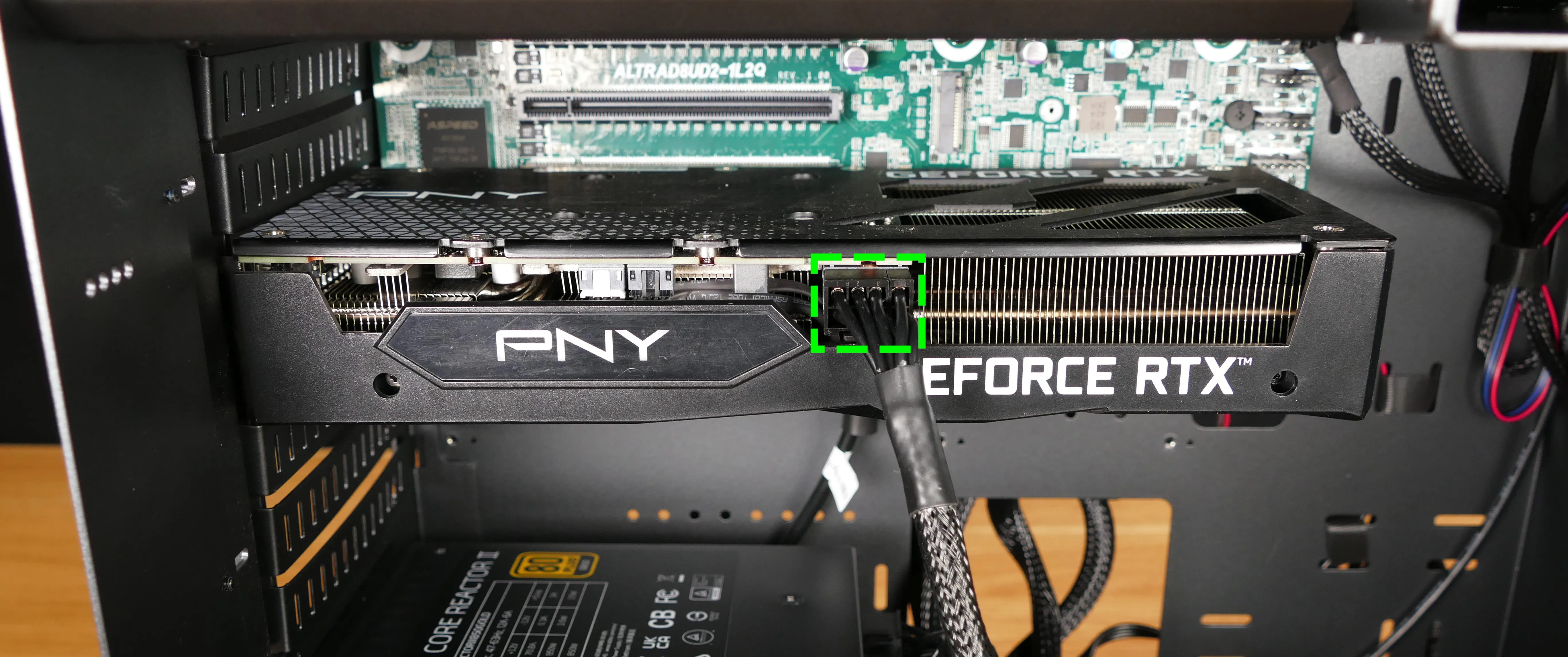
- Unscrew the two back screws holding the PCIe bracket in place, and remove the PCIe bracket (or slide it into the rightmost position).

- Pull the card out of the slot.
- There are no latches on the PCIe slots of the Thelio Astra motherboards.
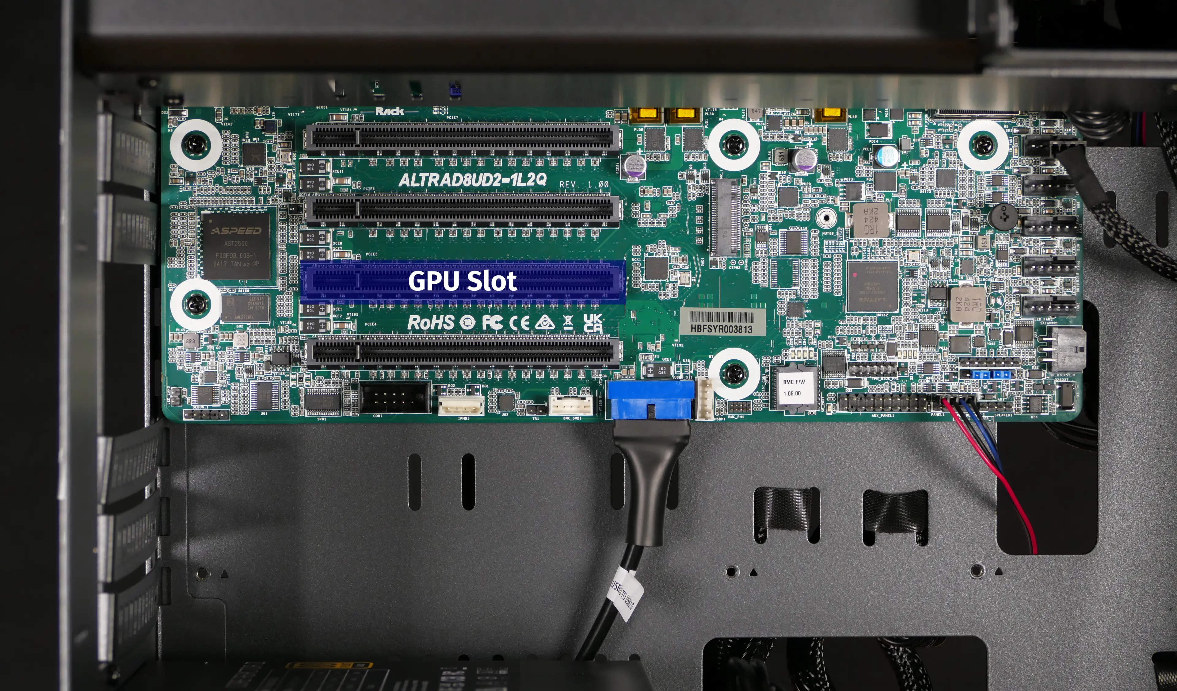
- After inserting the new GPU into its slot, connect the power cable.
- Once the GPU is installed, replace the back PCIe bracket, side brace, and top case.
- The GPU brace finger may need to be adjusted before the side brace can be reinstalled.
Replacing the CMOS battery:
The CMOS battery supplies power to the system's CMOS chip. UEFI settings and the computer's hardware clock are stored on the CMOS. If your system doesn't boot, you can reset the CMOS to force a low-level hardware reset. If your clock is constantly resetting, it's likely your CMOS battery needs to be replaced.
Warning (ingestion hazard): Keep batteries out of reach of children. Death or serious injury can occur if ingested. If a battery is suspected to be swallowed or inserted inside any part of the body, seek immediate medical attention. In the US, you can also call the National Battery Ingestion Hotline for guidance: 1 (800) 498-8666
Part numbers:
- The CMOS battery is a standard CR2032 battery. The stock battery is Toshiba brand.
Tools required: Cross-head (Phillips) screwdriver
Time estimate: 20 minutes
Difficulty: Medium ●
Steps to replace the CMOS battery (ALTRAD8UD2-1L2Q motherboard variant):
- Follow the steps above to remove the top case, remove the CPU duct, and remove the side brace.
- Depending on the size of your GPU, you may also need to remove the GPU to access the Clear CMOS Pad.
- Unplug the CMOS battery connector (highlighted cyan below) from the header next to the silver heatsink at the top left of the motherboard.

- If you are replacing the CMOS battery, pull it away from the Ethernet port casing.
- To reset the CMOS, bridge the contacts of the Clear CMOS Pad near the bottom-right corner of the motherboard (near the M.2 SSD).
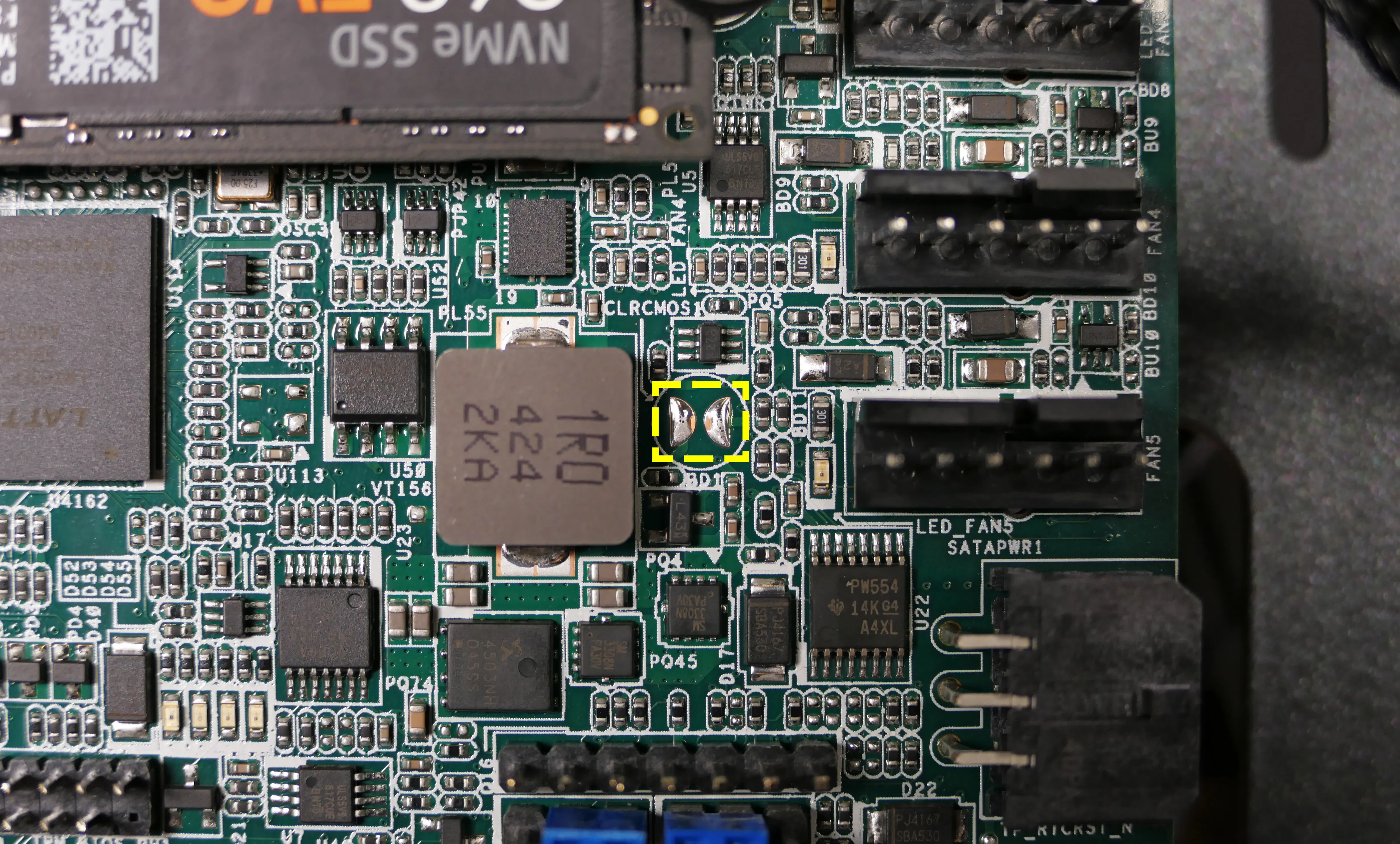
- Plug in the new CMOS battery (or re-connect the existing CMOS battery) and adhere it to the top of the Ethernet port casing.
- Replace the GPU, side brace, and top case.
Replacing the M.2 drives:
Thelio Astra A1-N1 has one or two M.2 storage slots on the motherboard, depending on the motherboard variant:
- The ALTRAD8UD-1L2T motherboard variant includes two M.2 slots.
- The ALTRAD8UD2-1L2Q motherboard variant (shown in the photos on this page) includes one M.2 slot.
All motherboard slots are M-key and support sizes 2280 and 2230.
Factory configurations offer up to four additional SSDs using a PCIe adapter card, not pictured in this manual.
Tools required: Cross-head (Phillips) screwdriver
Time estimate: 30 minutes
Difficulty: Medium ●
Steps to replace the M.2 drive:
- Follow the steps above to remove the top case, remove the side brace, and remove the GPU.
- Removing the GPU is optional to access the top slot (the only slot in the ALTRAD8UD2-1L2Q motherboard vairant), but still recommended for ease of access.
- Unscrew and remove the plastic-headed screw holding the M.2 drive in place.
- The M.2 drive will pop up at an angle and can be removed.

- To install a drive, insert it into the slot at an angle, then hold it against the motherboard while screwing in the plastic-headed screw.
- Replace the GPU, side brace, and top case as applicable.
Replacing the CPU fans:
Thelio Astra A1-N1 contains three 120mm CPU fans. One fan is mounted in the back of the CPU duct, while two others are mounted on the front and back of the CPU cooler's heatsink.
Part numbers:
- The duct-mounted CPU fan is a Be Quiet! Silent Wings 4 (BQ SIW4-12025-MF-PWM).
- The heatsink-mounted CPU fans are Arctic Freezer 4U fans.
- The heatsink-mounted fans are produced for the Arctic Freezer 4U-M Ampere CPU cooler, and it may not be possible to source them separately.
Tools required: Cross-head (Phillips) screwdriver
Time estimate: 25 minutes
Difficulty: Medium ●
Steps to replace the duct-mounted CPU fan:
- Follow the steps above to remove the top case and remove the CPU duct.
- Unscrew the four screws (two on each side) holding the fan bracket onto the duct.
- Removing the bracket from the duct is not required, but it makes removal and installation of the fan much easier.

- Unscrew the four screws attaching the bracket to the fan.
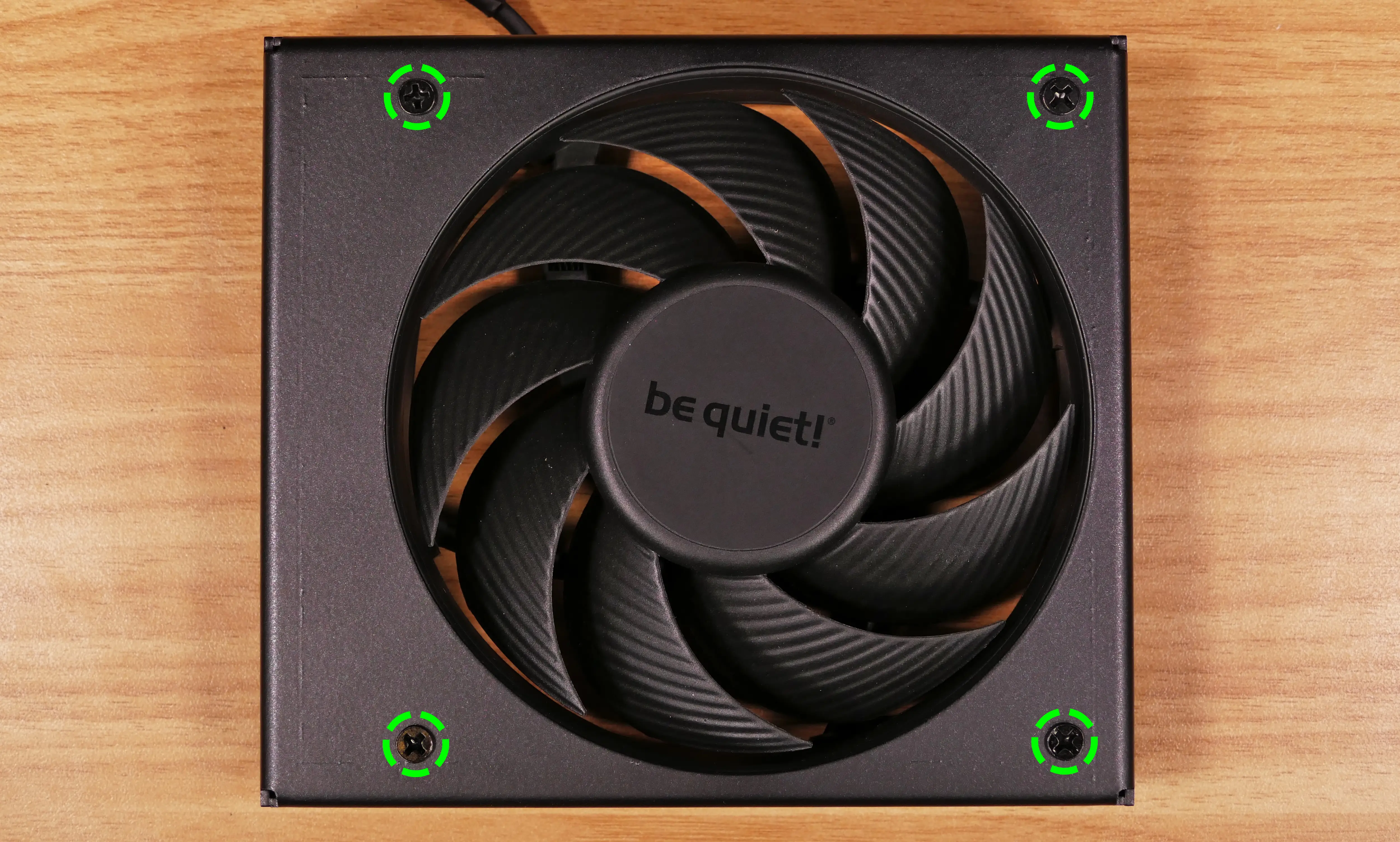
- When reinstalling the fan into the CPU duct:
- The spinning side should face inward (towards the front of the chassis), while the stationary label should face outward (towards the back of the chassis).
- The cable should point towards the fan connector (towards the top left, when viewed from the back).
- The fan bracket contains a cable channel in the corresponding corner.
- Overtightening the fan bracket's screws may cause fan noise; if the fan is creating excessive noise, try slightly loosening some of the screws.
Steps to replace the heatsink-mounted CPU fans:
- Follow the steps above to remove the top case and remove the CPU duct.
- You can optionally remove the side brace for easier access.
- Disconnect the rear cooler fan from the front cooler fan's Y-cable, and unplug the front cooler fan's Y-cable from the splitter board (if it wasn't already unplugged while removing the CPU duct).
- The heatsink fan cable connection points are highlighted red below.
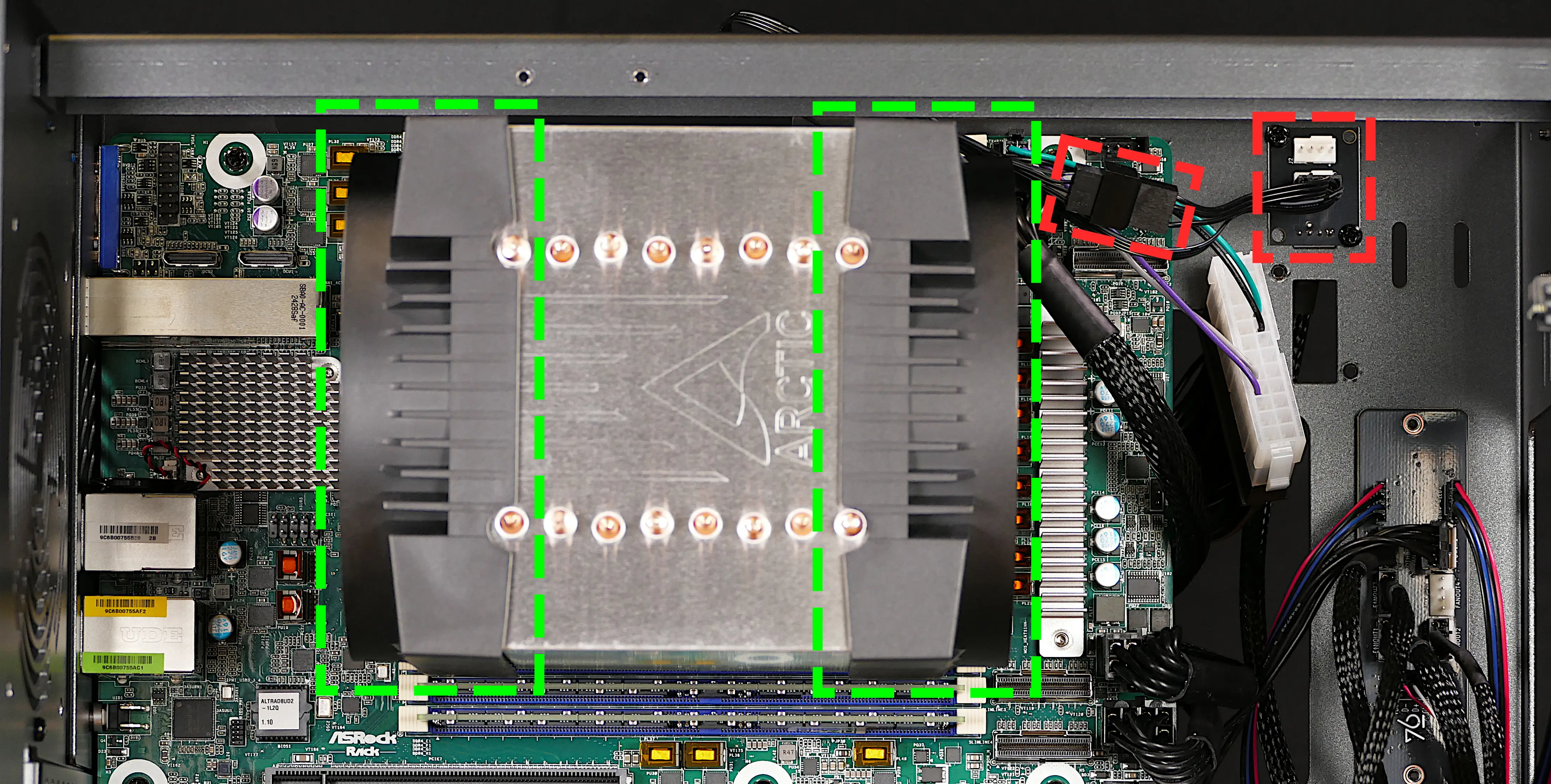
- Pull the fans (highlighted green above) directly out of the case, sliding them off the heatsink.
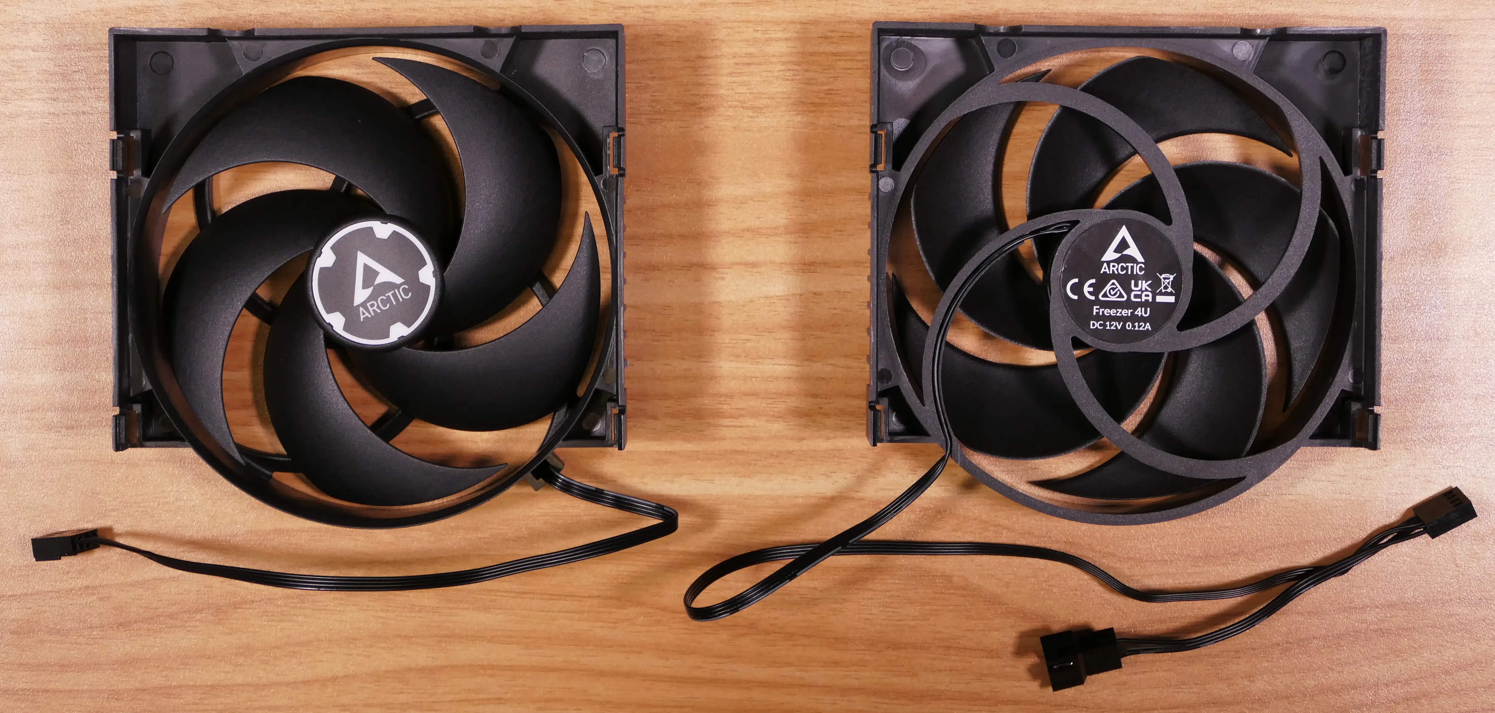
- When reinstalling the CPU heatsink fans, the fan with a normal cable goes on the back of the heatsink, while the fan with a Y-cable goes on the front.
Replacing the CPU cooler and CPU:
The CPU cooler dissipates heat from the CPU to the heatsink, where the CPU fans expel it from the system. Depending on your climate and the age of the machine, replacing the thermal paste between the CPU and the cooler/heatsink may help the system run cooler.
Part numbers:
- The CPU cooler is an Arctic Freezer 4U-M.
- The CPU uses an LGA 4926 socket.
Tools required: Cross-head (Phillips) screwdriver, six-point star (Torx T20) screwdriver, thermal paste
Time estimate: 45 minutes
Difficulty: High ●
Steps to remove the CPU cooler/thermal paste:
- Follow the steps above to remove the top case, remove the side brace, remove the CPU duct, remove the GPU, and remove the heatsink-mounted CPU fans.
- While holding the CPU cooler in place so it doesn't fall, loosen the screws to the left and right of the CPU cooler.
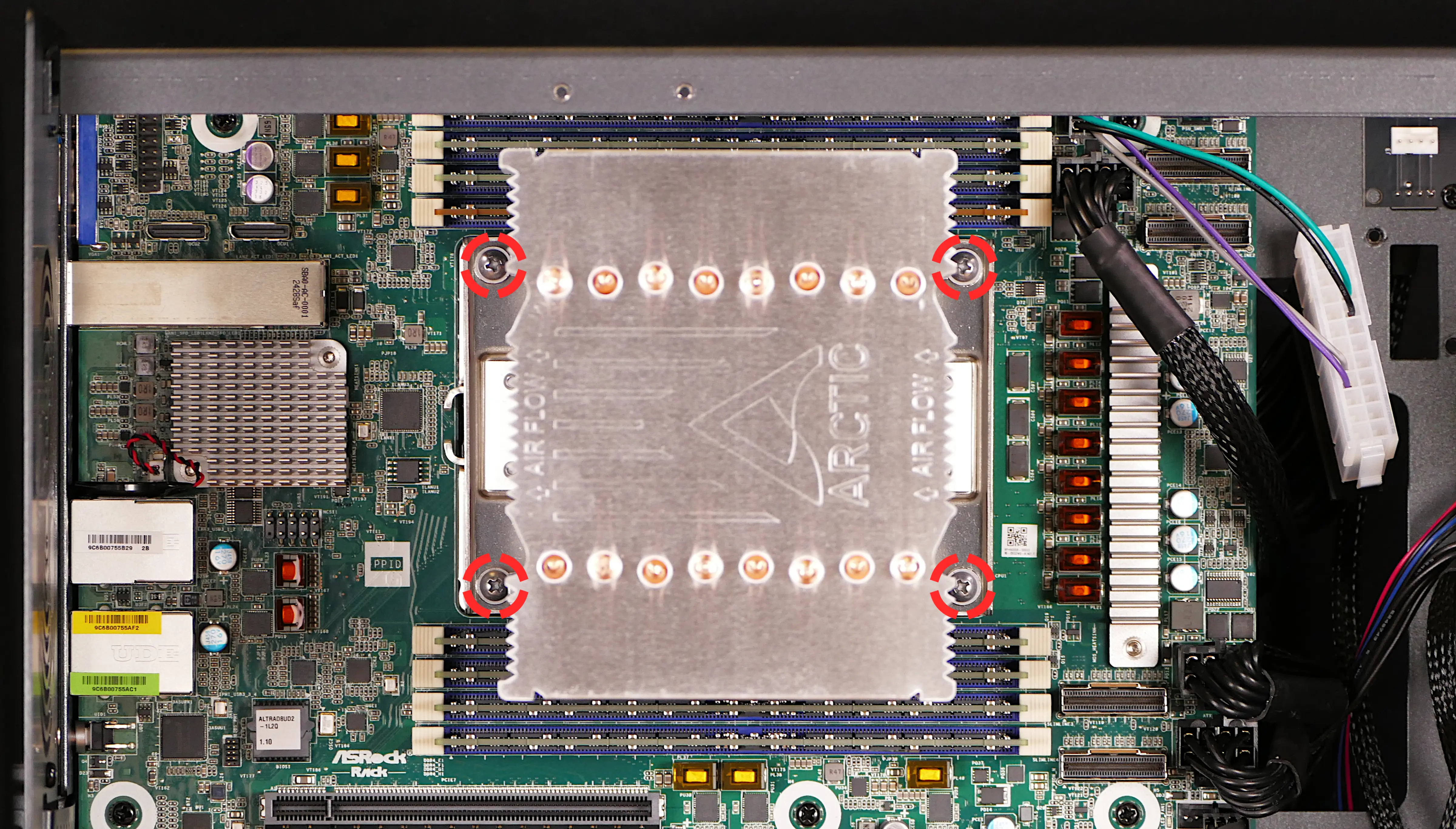
- Lower the cooler away from the CPU.
- Using a paper towel, clean the existing thermal paste off of the heatsink and CPU.
- Due to the design of the heatsink, some thermal paste may remain between the heatsink pipes. Only the flat section of the pipes that makes contact with the CPU needs to be cleaned.
- You may also use a small amount of rubbing alcohol if the old paste is dried or difficult to remove.

Steps to replace the CPU:
- Place the computer on its side so the motherboard is facing up.
- Using a Torx T20 screwdriver, unscrew the Torx screws in reverse order of the stamped numbers (unscrewing #1 last).
- Your motherboard may have four or five Torx screws on the CPU socket, depending on the revision.
- The screws are held captive and will not come apart from the CPU holder.
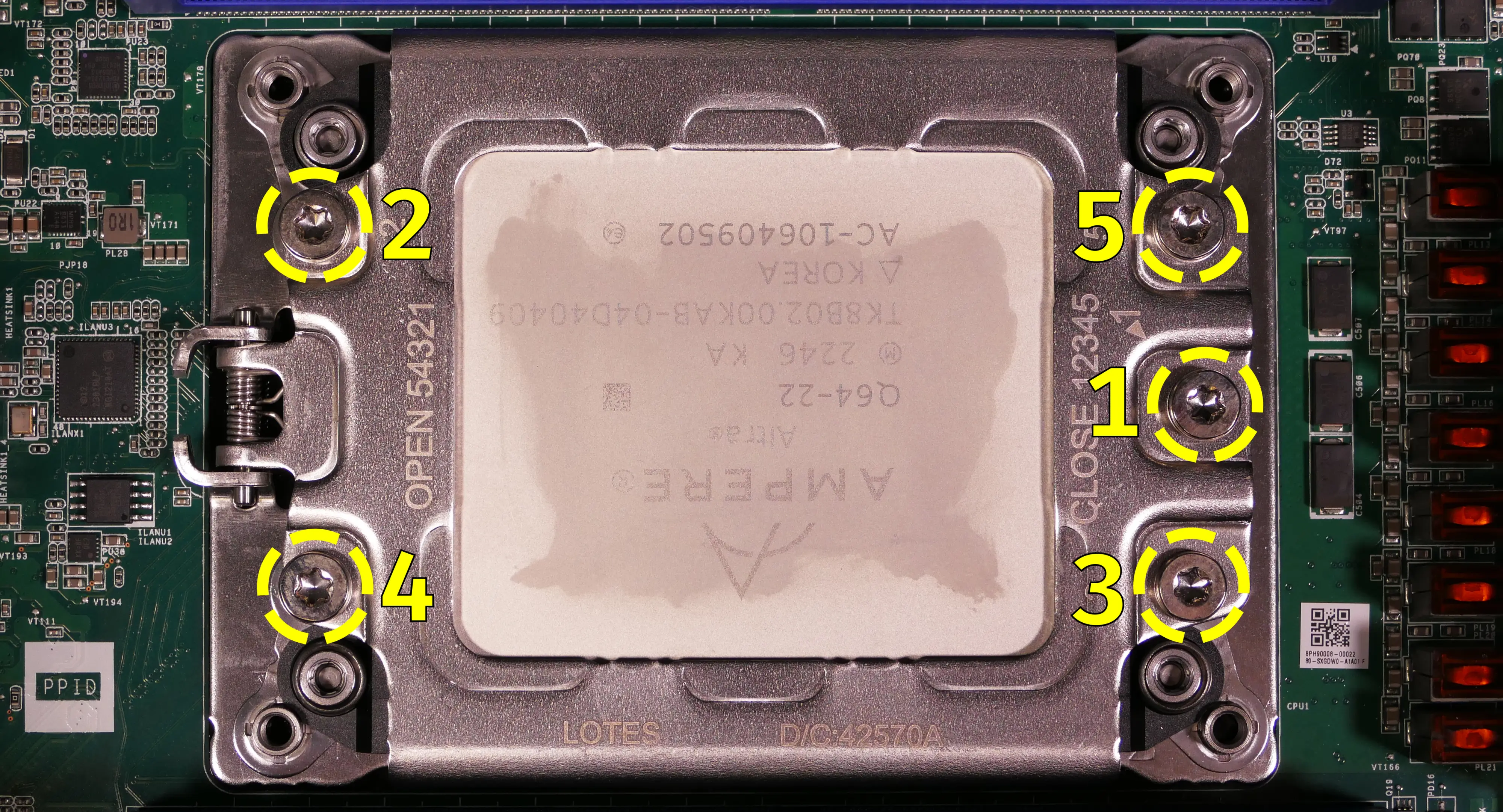
- The spring-loaded CPU holder will raise off of the motherboard.
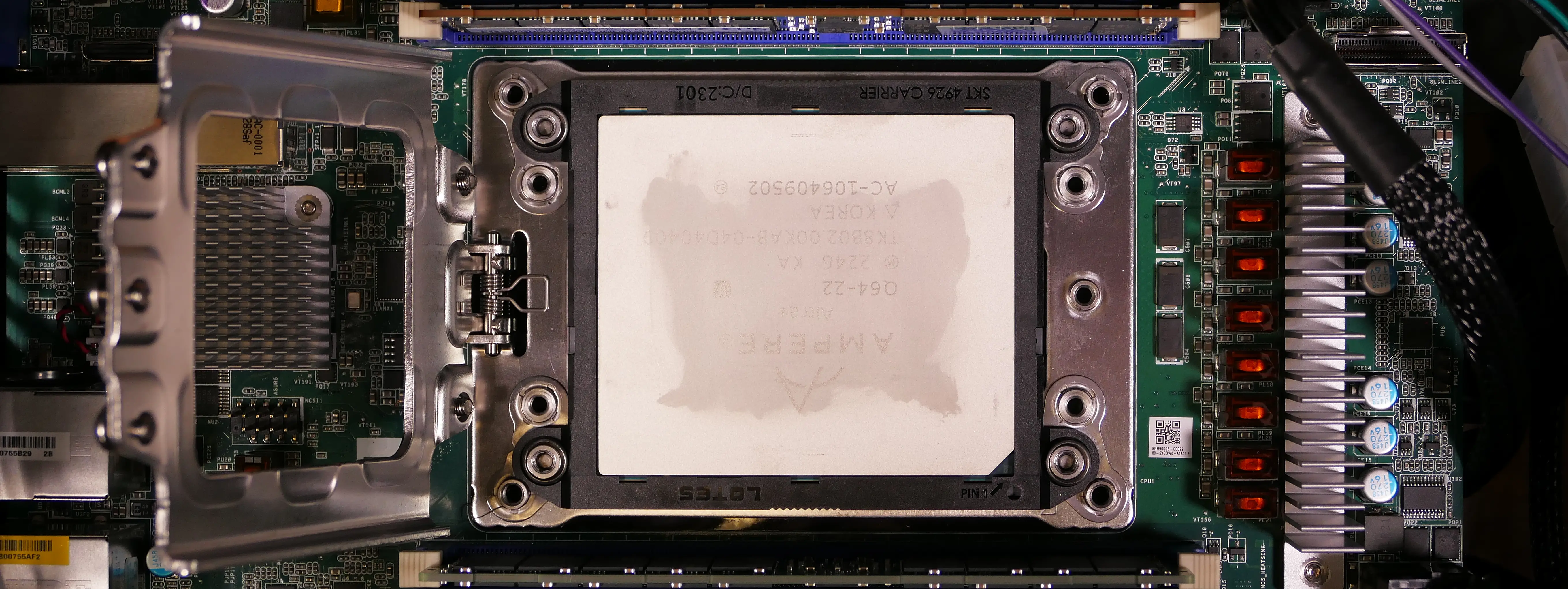
- Carefully lift the CPU's black plastic frame out of the CPU socket.
- Be careful not to bend any of the gold pins on the CPU socket, and do not touch the gold pads on the CPU.

- Gently place the new CPU into the socket.
- The diagonal-cut corner of the CPU (marked with a triangle on the bottom) should be oriented to match the triangle on the CPU socket, pointing towards the bottom right of the motherboard.
- Flip the CPU cover back onto the CPU.
- Screw in the CPU cover's Torx screws in the order of the stamped numbers (starting with #1).
Steps to install the thermal paste/CPU cooler:
- Draw an
Xshape of thermal paste onto the CPU.

- Place the CPU cooler onto the CPU; while holding it in place, screw in its four mounting screws.
- The cooler should be oriented so the Arctic logo faces the right side.
- Insert each screw partially, then finish tightening them all.
- Set the computer upright, then reinstall the cooler-mounted CPU fans, CPU duct, GPU, side brace, and top case.
Replacing the power supply:
The power supply unit (PSU) can be replaced with another unit of the same model.
Part numbers:
- The default PSU is the XPG Core Reactor II.
Tools required: Cross-head (Phillips) screwdriver
Time estimate: 45 minutes
Difficulty: Medium ●
Steps to replace the power supply:
- Follow the steps above to remove the top case, remove the side brace, and unplug the GPU (if installed).
- Unscrew the power supply bracket's left side from the bottom of the chassis.
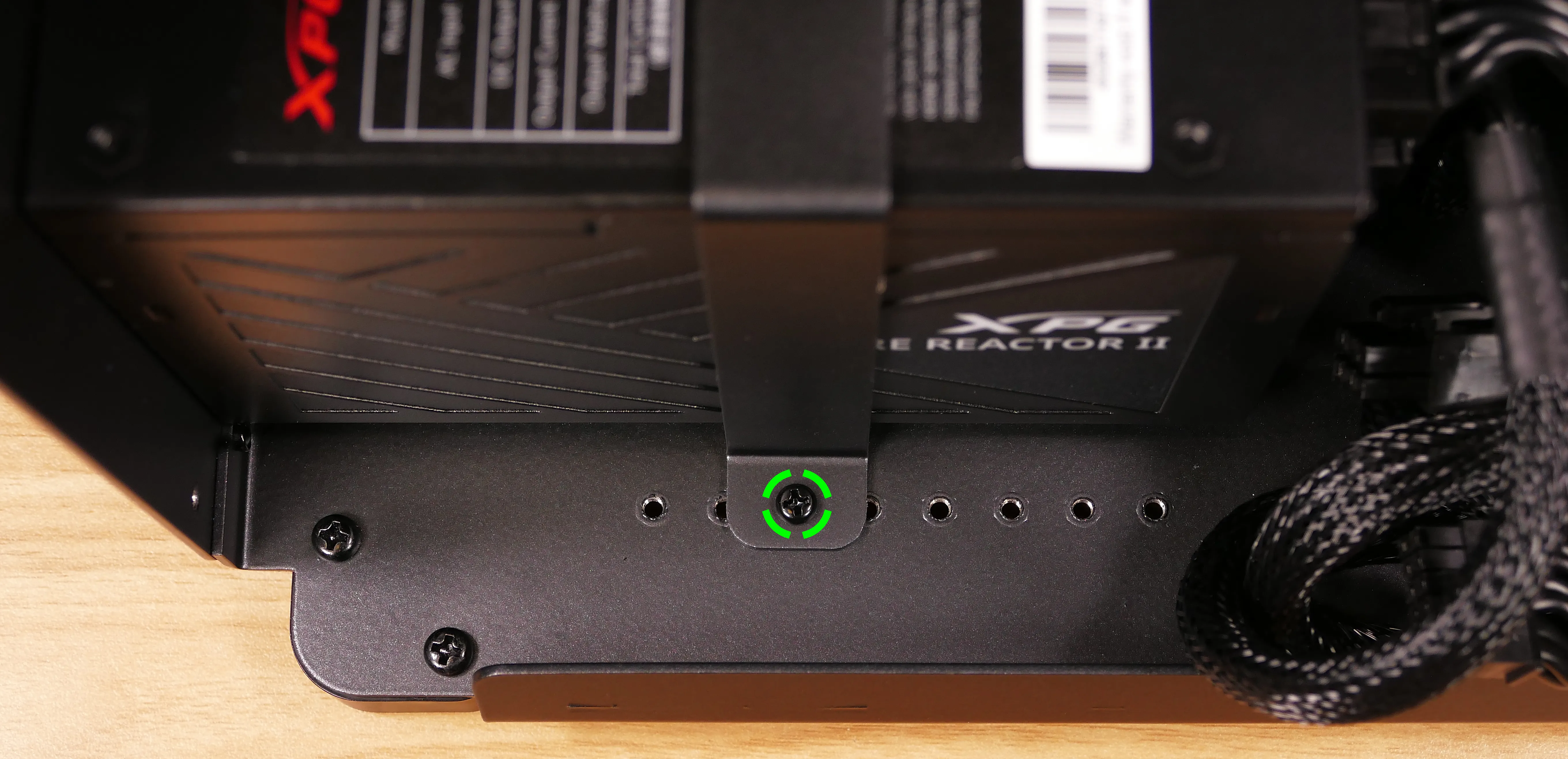
- Unscrew and remove the chassis spacer bracket on the right side of the chassis, then unscrew the power supply bracket's right side from the chassis.
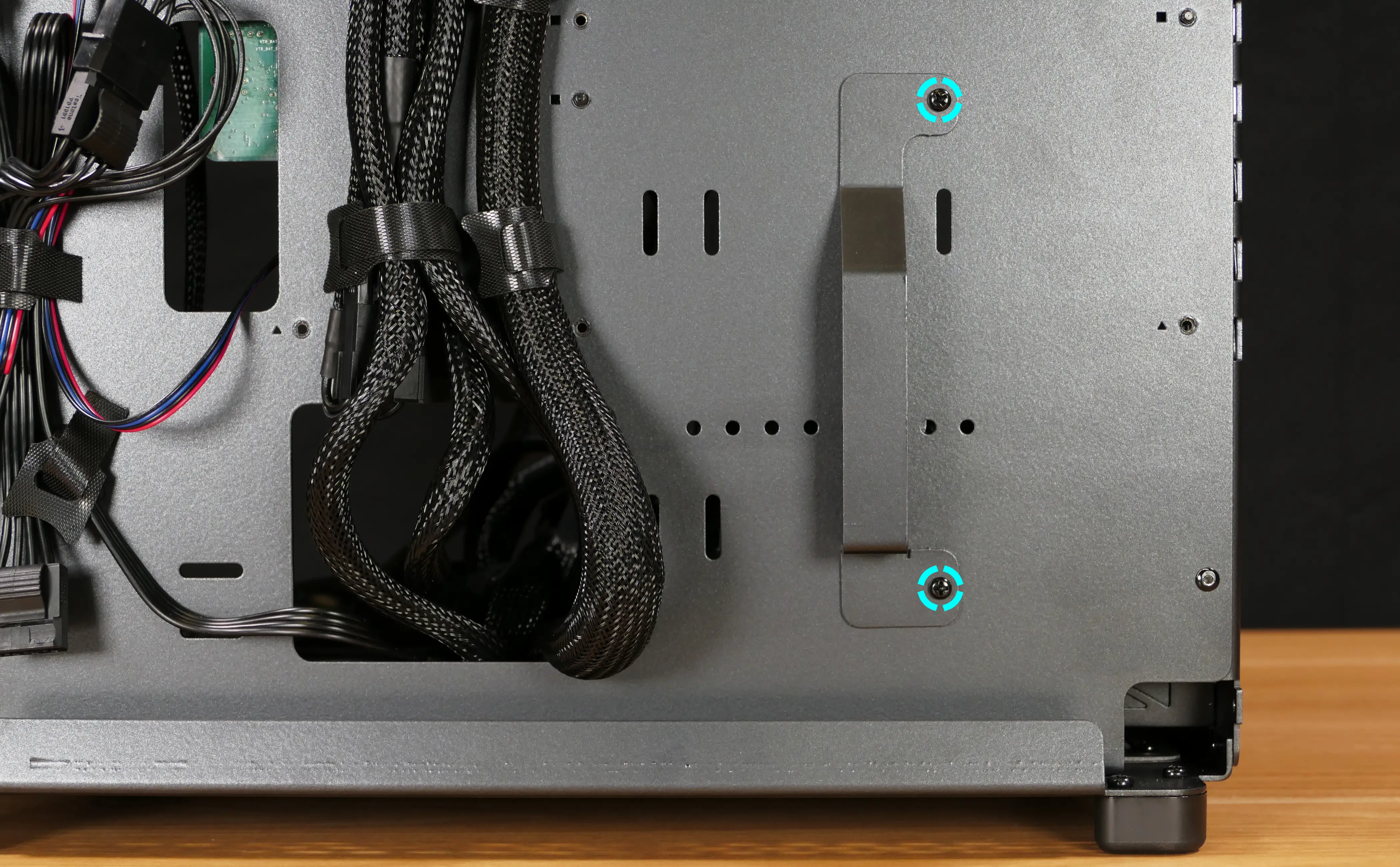
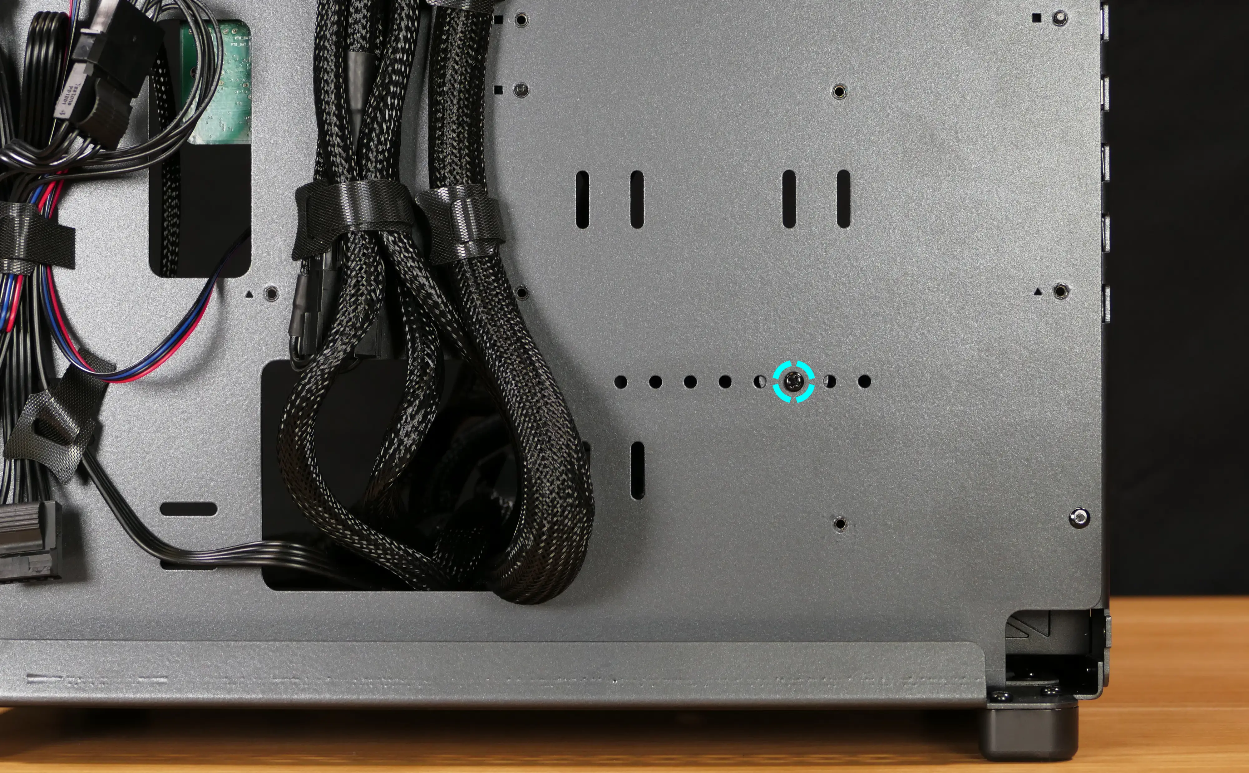
- Unscrew the power supply's four screws from the back of the chassis.

- Unplug all of the modular cabling from the back of the PSU.
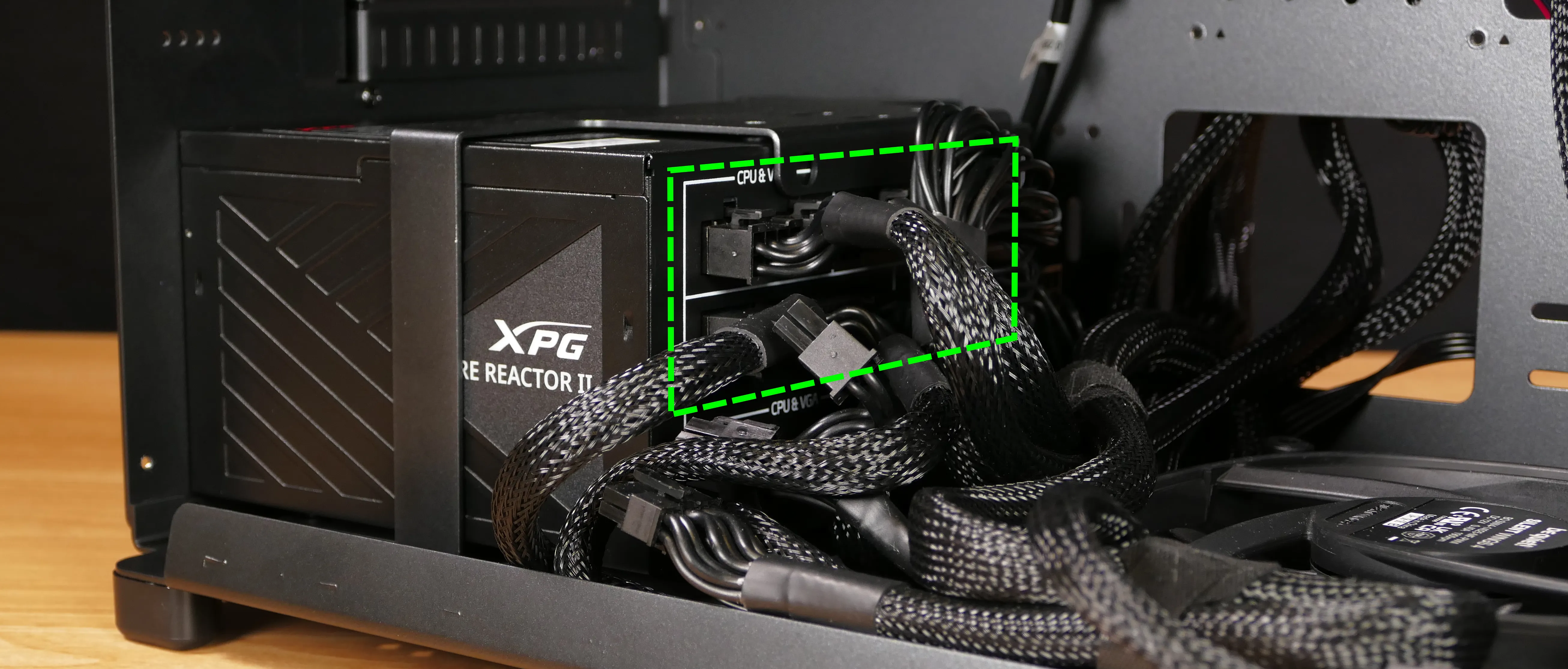
- Remove/replace the power supply.
- The replacement PSU should be installed with the fan facing the bottom of the case.
- Place the PSU on the rubber post and hold it against the screwholes in the back of the case while attaching it.
- Connect the power cables to the new power supply and GPU, then reinstall the PSU brace, side brace, and top case.
Replacing the Thelio Io board:
Named after Jupiter's moon Io, the Thelio Io daughterboard handles the front power button and fan control. If the Thelio Io board becomes defective, it can be replaced using the instructions below.
Part numbers:
- Thelio Astra A1-N1 uses Thelio Io version 2 (PCB revision thelio_io_2.3).
Tools required: Cross-head (Phillips) screwdriver
Time estimate: 30 minutes
Difficulty: High ●
Steps to replace the Thelio Io board:
- Follow the steps above to remove the top case.
- The CPU duct and side brace can optionally be removed to provide easier access to the cabling.
- Use the cutout on the front of the chassis to unplug all cabling from the Thelio Io board.
- The topmost connector requires pulling the white tab while unplugging.
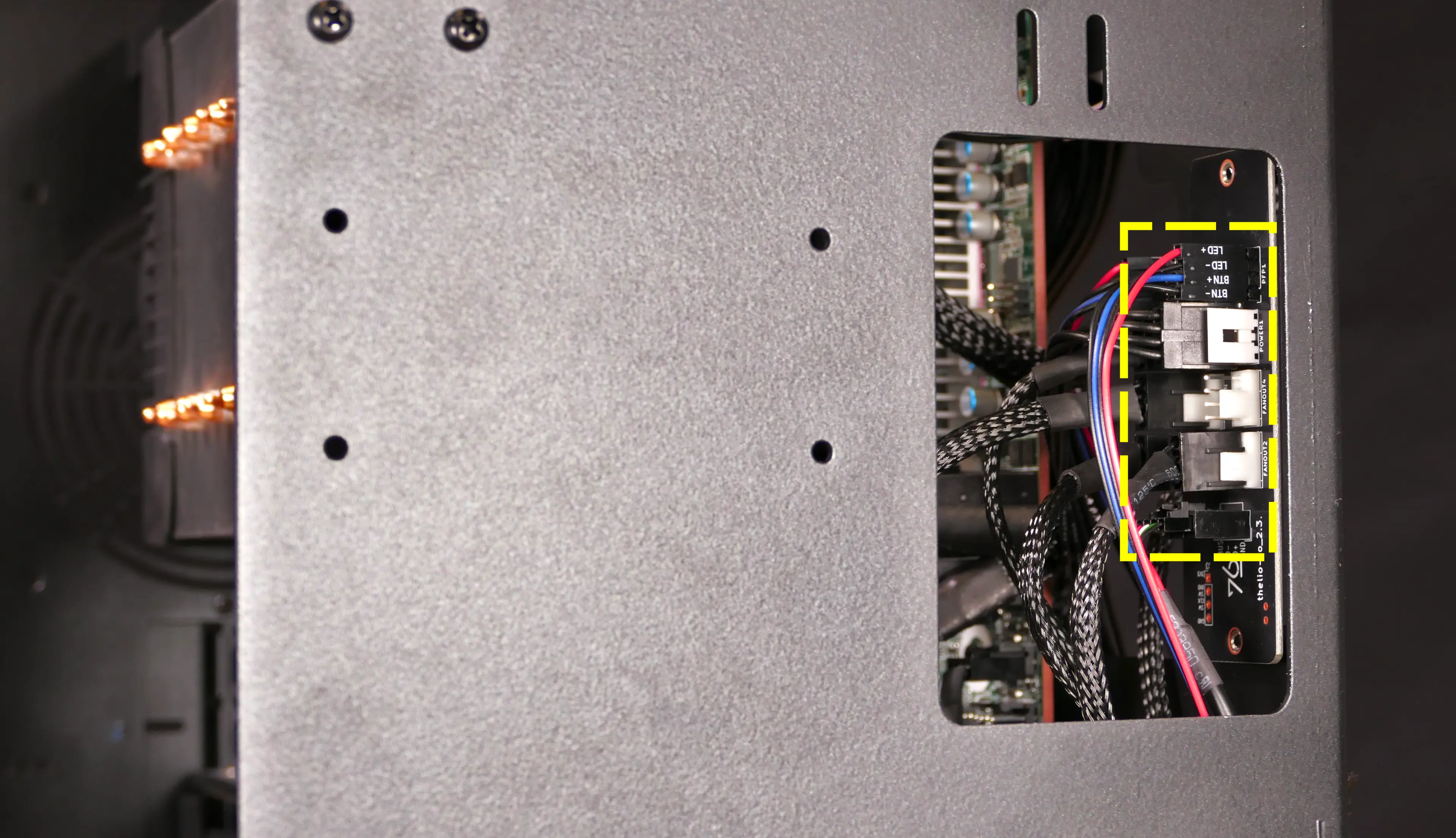
- Unscrew the two screws holding the daughterboard on from the right side of the chassis.
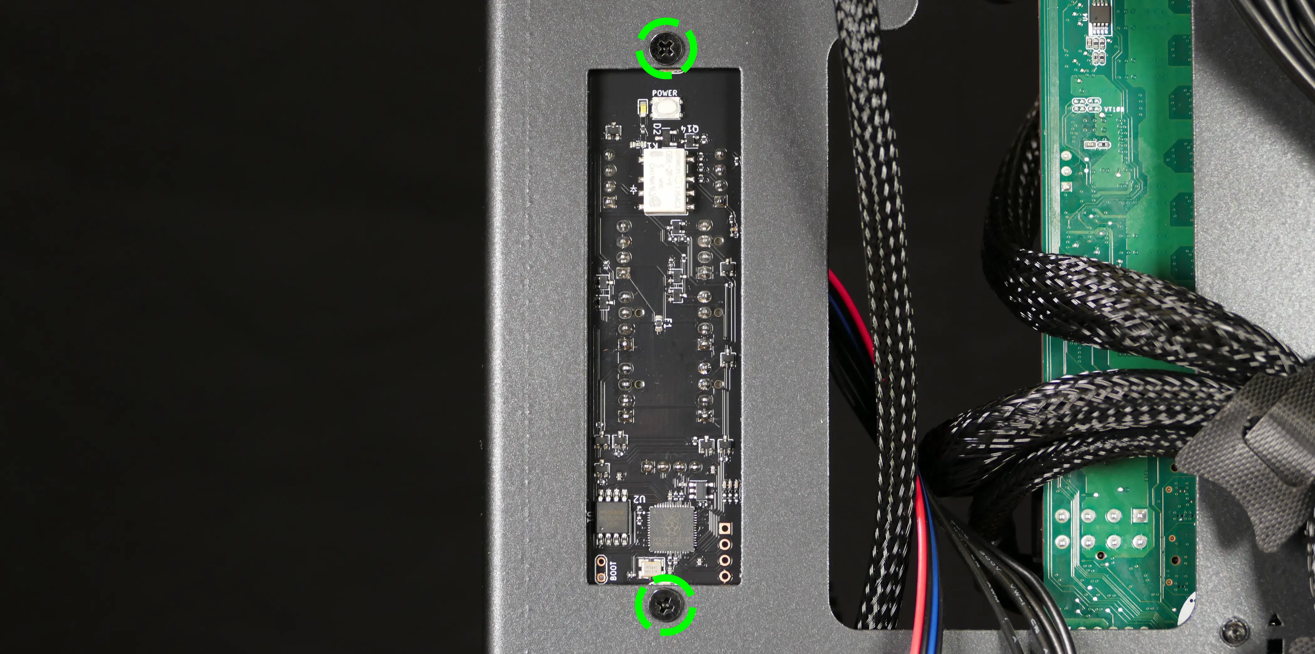
- Screw in the new Thelio Io board and reconnect the wiring.
Thelio Io wiring guide:

-
When wiring the Thelio Io board, refer to the port labels and the following guide.
FANOUT1/CPU FAN- to the top fan splitter (connecting to the CPU fans).FANOUT4/AUX FAN- disconnected.FANOUT2/INTAKE FAN- to the bottom case fan.FANOUT3/GPU FAN- to the side brace fan splitter.- May be disconnected by default if no side fan is ordered as factory configuration.
FANIN1/MOTHERBOARD FAN INPUT- to theFAN1header on the right side of the motherboard, highlighted cyan below.
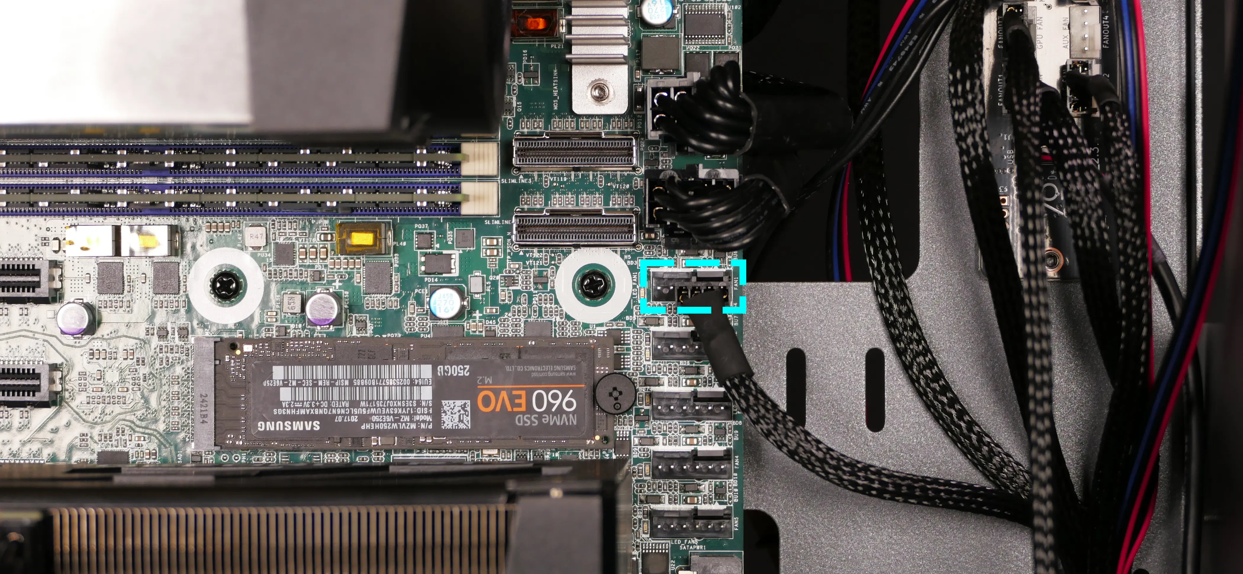
POWER1/POWER INPUT- to the power supply via 4-pin Molex connector.- The white plastic clip needs to be held away from the connector to unplug this cable from the Thelio Io board.
PFP1/FRONT PANEL- to the power button receptacle on the front panel.- On the Thelio Io board, the wire color order (from top to bottom) is red, black, blue, black.
- On the power button receptacle, the wire color order (from left to right) is red, black, blue, black.
PMB1/MOTHERBOARD- to the first four pins of thePANEL1header at the bottom right of the motherboard, highlighted green below.- On the Thelio Io board, the wire color order (from top to bottom) is red, black, blue, black.
- On the motherboard, the wire color order (from left to right) is red, black, blue, black.
USB- to theUSB3_3_1header on the bottom edge of the motherboard (via an included USB 2.0 to 3.0 adapter cable), highlighted yellow below.- A small clip needs to be held down to unplug this cable from the Thelio Io board.
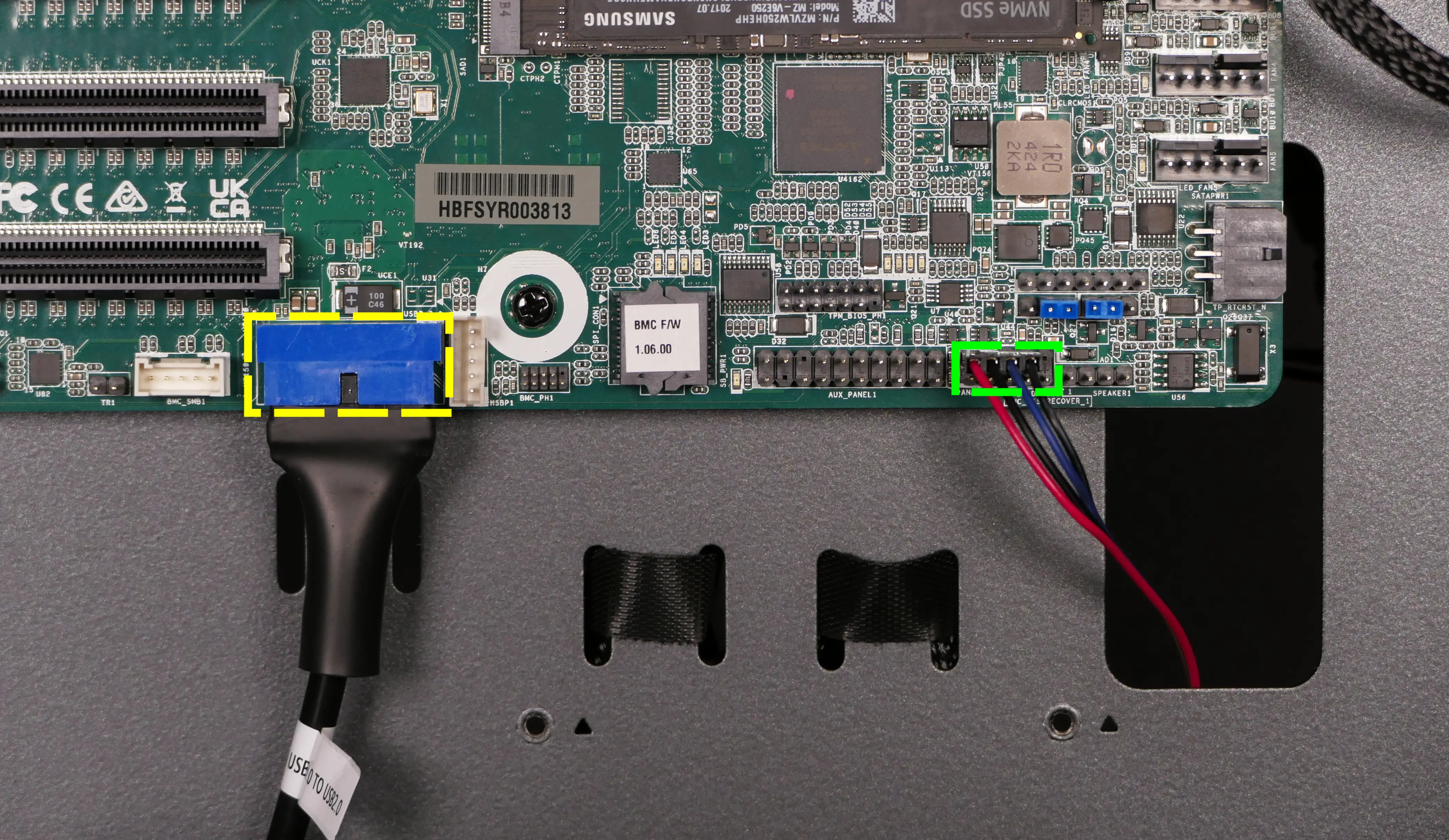
Troubleshooting the power button:
If the front power button doesn't power the machine on or doesn't light up when the system is powered on, try the following troubleshooting steps:
- Ensure the system powers on normally using the internal power button.
- Reseat the front power button to ensure it's making proper contact.
- Check the wiring for the front power button.
- Replace the front power button, if necessary.
Tools required: Cross-head (Phillips) screwdriver (optional)
Time estimate: 20 minutes
Difficulty: Medium ●
Steps to power the machine on using the internal power button:
- Follow the steps above to remove the top case.
- Ensure the system is plugged into power, and the power supply switch is in the 1 (On) position.
- Push the small button labeled
POWERon the Thelio Io board.- The white LED to the left of the button lights up to indicate when the system is powered on (and pulses when the system is suspended).
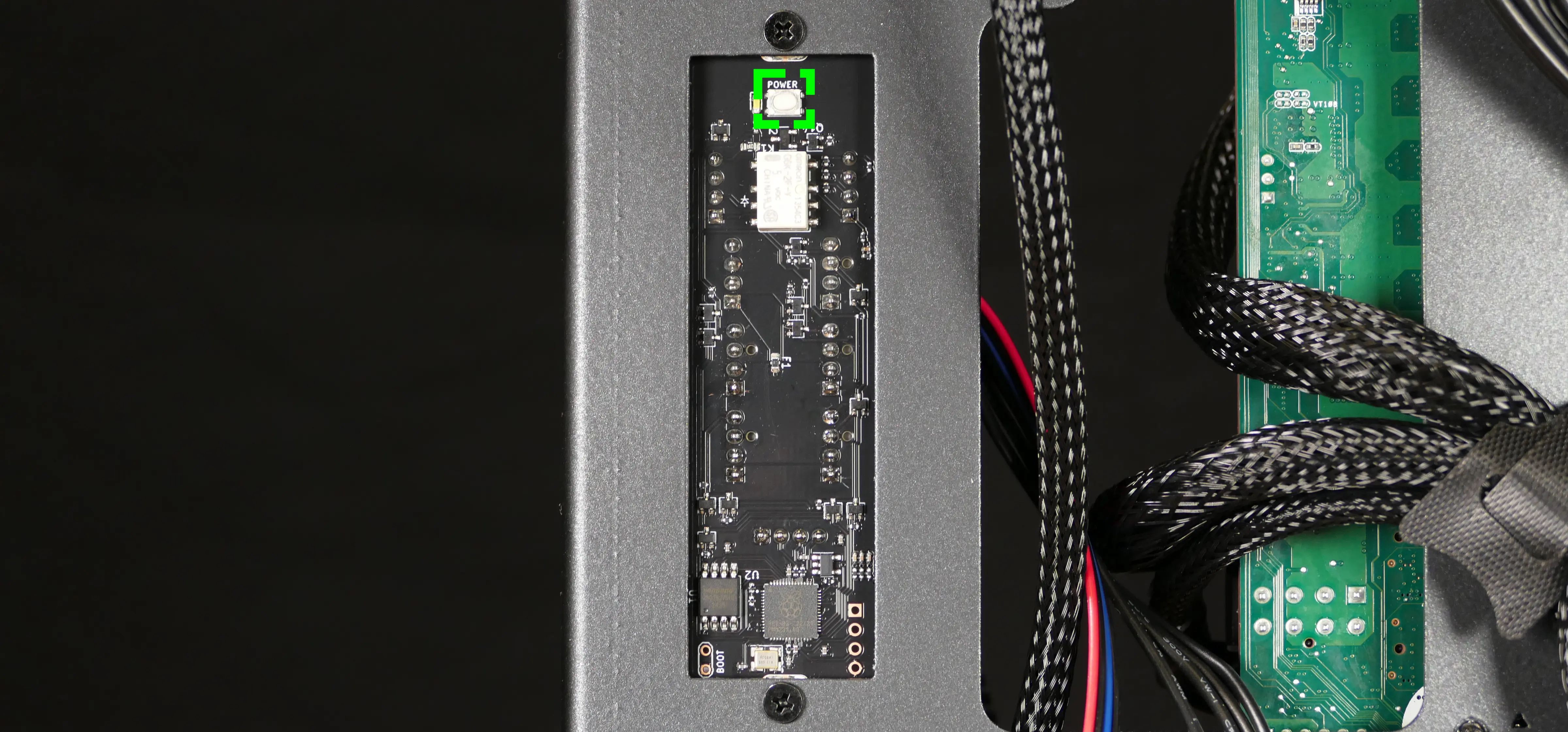
- If the Thelio Io
POWERbutton powers the machine on and the LED lights up, then the issue is either the front power button or its connection to the Thelio Io board. Check the front power button wiring. - If the Thelio Io
POWERbutton and/or LED does not work, then the issue is either the Thelio Io board or its connection to the motherboard. Check the wiring between the Thelio Io board and the motherboard.
Steps to check the front power button wiring:
- Follow the steps above to remove the top case.
- On the back of the power button, the four pins should be connected to the four-wire connector as follows:
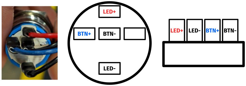
- On the front power button receptacle, the four-pin connector should have the red wire on the left and the black wire on the right (when viewed from the back of the computer.)
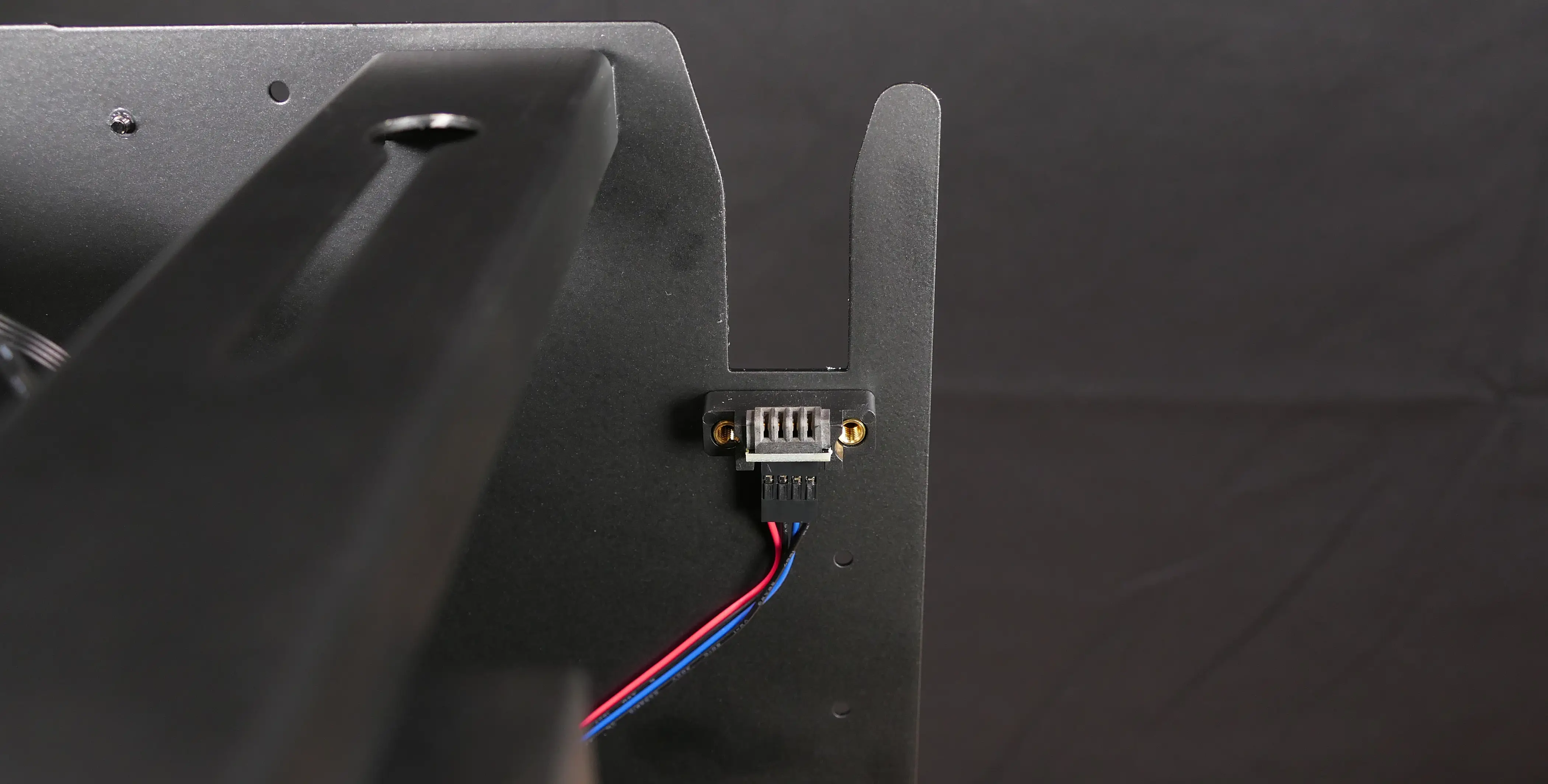
- The front power button receptacle should plug into the
PFP1port on the Thelio Io board, with the red wire on the top (see the Thelio Io wiring guide.)
Steps to replace the power button:
- Follow the steps above to remove the top case.
- Follow the instructions in the Replace the Thelio Power Button support article.
Thelio Astra (Ubuntu 24.04 LTS Setup)
Thelio Astra uses an Ampere processor supporting AArch64 (ARM64) versions of Linux. If you need to reinstall the operating system, the instructions on this page can be used to set up Ubuntu 24.04 LTS.
Operating system download:
- Download the Ubuntu Desktop for ARM 24.04.1 LTS daily ISO from 8/27/2024.
- This was the latest daily ISO available for arm64 at the time this guide was last updated. Newer daily ISOs may work, but will have a different SHA256SUM in the next step.
- Verify that the SHA256SUM matches the following:
839627cb19b70d8c4da64c789ecbdec6af14f0017d925ab086c9ad7e93f2c325- You can run
sha256sum noble-desktop-arm64.isoto check the SHA256SUM from the terminal, or use a GUI application such as Popsicle.
- You can run
- Write the ISO to a USB flash drive using an application such as Popsicle or Etcher.
Hardware preparation:
- It's recommended to fill all 8 memory channels for maximum CPU performance.
- When using Ampere Altra (non-Max) CPUs, the top two PCIe x16 slots (closest to the CPU) will run at x8 speeds. Place x16 devices into the bottom two slots for optimal performance.
- Install all required hardware, including GPUs and WiFi cards, before installing the OS.
- The system firmware version must be
3.02or above in order to support early boot output on NVIDIA GPUs. - There is a jumper labeled
BMC_DIS(BMC Disabled) that can bypass the requirement that the BMC boots before the power button is functional.- Bridging the second and third pins disables waiting for the BMC on boot. The default behavior (enabling the BMC) is the same as if the first and second pins are bridged.
Operating system installation:
- Power on the system. Press the
F11key when the firmware splash screen appears to open the boot menu. - In the boot menu, select the option to boot the installation media (e.g.
UEFI OS (Linux File-Stor Gadget). - Proceed through the graphical Ubuntu installation wizard.
System76 Driver installation:
- Ensure that DMI information is properly set at this point. If not, set it and reboot.
- If you are reinstalling your OS and have not re-flashed your firmware from a non-System76 source, then the DMI information should already be set correctly.
- Install all available operating system updates:
sudo apt update sudo apt full-upgrade - Add the System76 PPA with the following command:
sudo add-apt-repository ppa:system76-dev/stable - Install the System76 driver.
- If your Thelio Astra contains an NVIDIA GPU, use the following command, which includes a System76-packaged NVIDIA driver along with other drivers and utilities:
sudo apt install system76-driver-nvidia - Otherwise, use the following command to only install non-NVIDIA-related drivers and utilities:
sudo apt install system76-driver
- If your Thelio Astra contains an NVIDIA GPU, use the following command, which includes a System76-packaged NVIDIA driver along with other drivers and utilities:
- Install all available OS updates again. This may downgrade some packages as they pull the version from the System76 PPA:
sudo apt update sudo apt full-upgrade - Reboot the system with the GUI or with the
rebootcommand.
Thelio Astra (Ubuntu 20.04 LTS Setup)
Thelio Astra uses an Ampere processor supporting AArch64 (ARM64) versions of Linux. If you need to reinstall the operating system, the instructions on this page can be used to set up Ubuntu 20.04 LTS.
Operating system download:
- Download the Ubuntu Server for ARM 20.04.5 LTS ISO.
- Verify that the SHA256SUM matches the following:
e42d6373dd39173094af5c26cbf2497770426f42049f8b9ea3e60ce35bebdedf- You can run
sha256sum ubuntu-20.04.5-live-server-arm64.isoto check the SHA256SUM from the terminal, or use a GUI application such as Popsicle.
- You can run
Hardware preparation:
- It's recommended to fill all 8 memory channels for maximum CPU performance.
- When using Ampere Altra (non-Max) CPUs, the top two PCIe x16 slots (closest to the CPU) will run at x8 speeds. Place x16 devices into the bottom two slots for optimal performance.
- Install all required hardware, including GPUs and WiFi cards, before installing the OS.
- The system firmware version must be
3.02or above in order to support early boot output on NVIDIA GPUs. - There is a jumper labeled
BMC_DIS(BMC Disabled) that can bypass the requirement that the BMC boots before the power button is functional.- Because the BMC may be necessary to complete the initial setup, use of this jumper is not recommended until initial setup is complete.
- Bridging the second and third pins disables waiting for the BMC on boot. The default behavior (enabling the BMC) is the same as if the first and second pins are bridged.
Firmware preparation:
- Plug the last ethernet port (closest to the PCIe slots) into to a DHCP-capable network where you already have another computer connected.
- This is the BMC's ethernet port, which will enable remote server management.
- Power on the system. Press the
F2key when the firmware splash screen appears to enter the firmware setup menu. - Navigate to the
Advancedtab, then select theNetwork Stack Configurationitem. SwitchNetwork StacktoDisabled. This will reduce boot times by disabling network booting, which will not be used in this guide. - Navigate to the
Server Mgmttab, then select theBMC Network Configurationitem. Note theStation IP address, which is how you will connect to the BMC's web interface later. - Navigate to the
Exittab and chooseSave Changes and Exit. When prompted, select yes. - After the system reboots, power it off to prepare for the next task.
BMC interface preparation:
- Open a web browser on another computer that is on the same network as the BMC. Navigate to the URL
https://AAA.BBB.CCC.DDD, replacingAAA.BBB.CCC.DDDwith the station IP address recorded before. - A login screen should appear. The default username is
rootand the default password is0penBmc.- The default password starts with a zero
0, not the letterO.
- The default password starts with a zero
- Under the
Operationsmenu, select theVirtual mediaitem. Click onAdd file, and in theFile Uploaddialog, choose theubuntu-20.04.5-live-server-arm64.isofile that you downloaded and verified before. Click onStart; a notification should briefly appear in the top right corner indicating success. - Under the
Operationsmenu, select theSOL consoleitem. This will show the system's serial output, which allows viewing Linux kernel output if it does not show up on the connected display.
Operating system installation:
- Plug the second to last ethernet port (above the BMC's ethernet port) into a DHCP-capable network with internet access.
- Power on the system. Press the
F11key when the firmware splash screen appears to open the boot menu. - In the boot menu, select the option that starts with
UEFI OS (Linux File-Stor Gadget. - Navigate to the
Boot and Install with the HWE kerneloption and presseto edit it. - Move the cursor to the line starting with
linux. In between/casper/hwe-vmlinuzand---, replacequiet splashwithconsole=tty0 nomodeset fsck.mode=skip, ensuring that there are spaces before and after these added arguments. PressF10to boot.- The first added argument,
console=tty0, tries to get Linux console output to show up on a connected display. - The second added argument,
nomodeset, works around potential nouveau driver crashes when NVIDIA graphics cards are used. - The third added argument,
fsck.mode=skip, will skip filesystem checks, which can take a long time.
- The first added argument,
- It will take some time to boot to the installer. If no output is seen, check the
Serial over LAN (SOL) consolepage in the BMC web interface. - Select the desired language.
- If you are prompted to apply an installer update, choose
Continue without updating. - On the
Keyboard configurationpage, select the desired keyboard layout and variant. SelectDoneto continue. - On the
Network configurationpage, you should have a successfully connected ethernet port. SelectDoneto continue. - On the
Proxy configurationpage, enter any required proxy (this should almost always be left blank). SelectDoneto continue. - On the
Ubuntu archive mirror configurationpage, the default mirror for packages will be tested. When it completes, selectDoneto continue. - On the
Guided storage configurationpage, selectUse an entire disk, and choose the desired disk. Leave theSet up this disk as an LVM groupoption enabled. SelectDoneto continue. - On the
Storage configurationpage, you can review the disk configuration. SelectDoneto continue. A warning will be shown; selectContinue. - On the
Profile setuppage, enter the following information (or substitute your own information):Your name:System76Your servers name:system76-pcPick a username:system76Choose a password:system76Confirm your password:system76
- On the
SSH setuppage, leaveInstall OpenSSH serverunselected. SelectDoneto continue. - On the
Third-party driverspage, leave any aptions unselected. SelectContinueto continue. - On the
Featured Server Snapspage, leave all options unselected. SelectDoneto continue. - On the
Installing systempage, installation progress will be shown. This may take some time to finish. When it is complete, selectReboot Now. - You may be prompted to remove the installation medium. Navigate in the BMC web interface to the
Operationsmenu andVirtual mediapage. Click on theStopbutton. A notification should briefly appear in the top right corner indicating success. Press Enter on the system to reboot.
Desktop environment installation:
- The system will boot to a terminal login prompt. Log in with
system76as the username andsystem76as the password (or your own credentials).- You may need to log in with the BMC serial console if the physical display does not show a prompt.
- Upgrade the system with the following commands:
sudo apt update sudo apt full-upgrade - Install the NVIDIA driver with the following command. The 550 driver is currently only packaged with the server variant for 20.04.
sudo apt install nvidia-driver-550-server - Install the default Ubuntu desktop environment with the following command. This will download a lot of packages and take a while to install:
sudo apt install ubuntu-desktop - At this point, NetworkManager will be installed alongside systemd-networkd, which causes boot delays as they both wait for network completion. The following steps will disable systemd-networkd in favor of NetworkManager, which has better integration with the Ubuntu desktop.
- A. Disable and mask systemd-networkd services with the following commands:
sudo systemctl disable systemd-networkd.service systemd-networkd.socket sudo systemctl mask systemd-networkd.service systemd-networkd.socket - B. Edit the netplan configuration with
sudo nano /etc/netplan/00-installer-config.yamland replace all of the contents with the following:network: version: 2 renderer: NetworkManager - C. Regenerate the netplan configuration by running the following command:
sudo netplan generate
- A. Disable and mask systemd-networkd services with the following commands:
- Reboot by running
sudo reboot. - You should see a login screen, where you can log in to the
System76user with the passwordsystem76(or log into your own account).- If you don't see a login screen, try a different display connection type (e.g. DisplayPort instead of HDMI) and/or a different display.
- After logging in, initial setup will appear.
- A. On the
Online Accontspage, clickSkipto continue. - B. On the
Livepatchpage, clickNextto continue. - C. On the
Help improve Ubuntupage, selectNo, don't send system info, then clickNextto continue. - D. On the
Privacypage, leaveLocation Servicesunselected. ClickNextto continue. - E. On the
Ready to gopage, clickDone.
- A. On the
- Default additional ethernet connections will repeatedly fail to connect. Run
nm-connnection-editorto open the connection manager and remove them.
System76 Driver installation:
- Ensure that DMI information is properly set at this point. If not, set it and reboot.
- If you are reinstalling your OS and have not re-flashed your firmware from a non-System76 source, then the DMI information should already be set correctly.
- Add the System76 PPA with the following command:
sudo add-apt-repository ppa:system76-dev/stable - Install the System76 Driver with the following command:
sudo apt install system76-driver - Upgrade the system with the following commands. This may downgrade some packages as they pull the versions from the System76 PPA:
sudo apt update sudo apt full-upgrade - Reboot the system with the
rebootcommand.
Thelio Major (thelio-major-r5-n3)
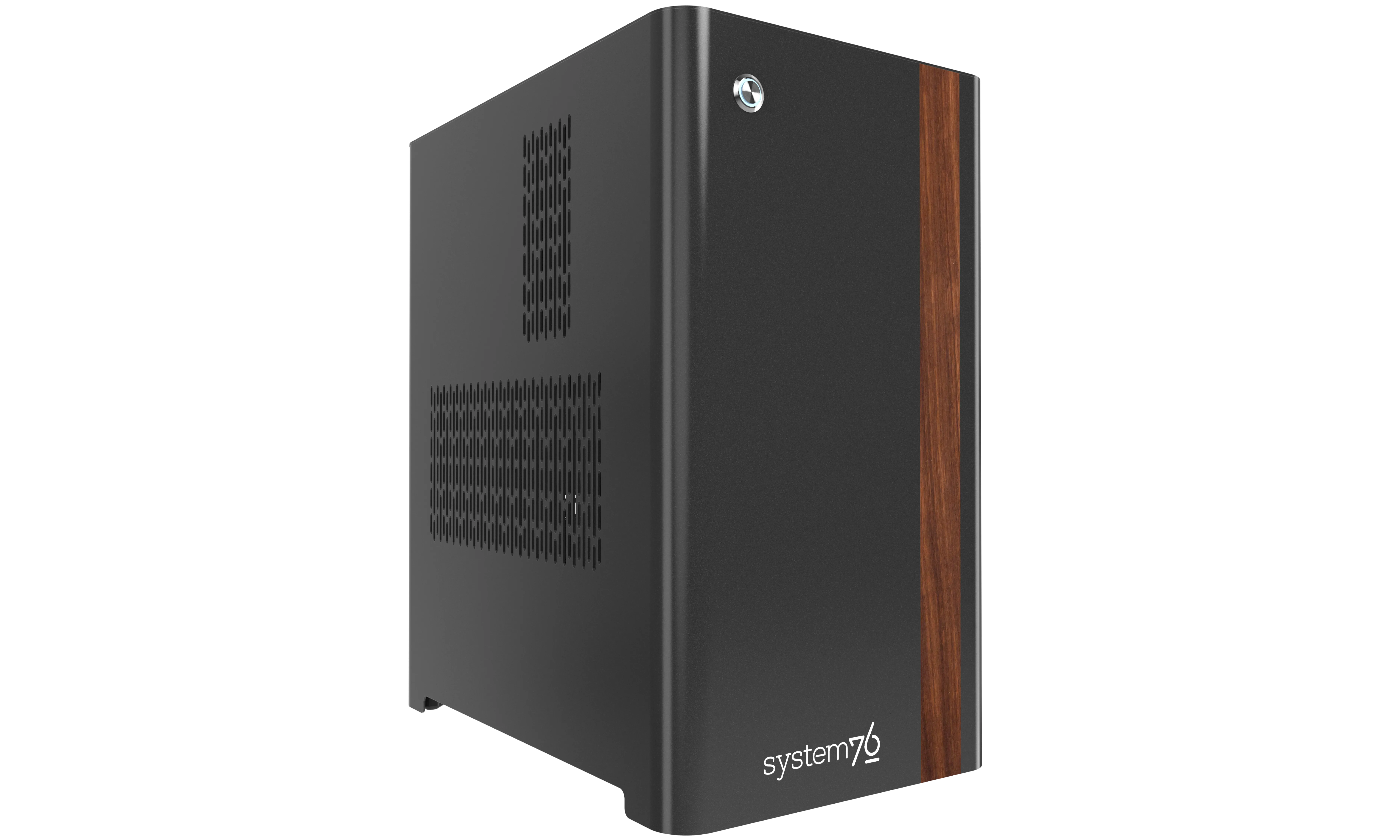
The System76 Thelio Major is a desktop with the following specifications:
- Processor options
- Supports AMD Threadripper 7000 series (Zen 4) CPUs
- Motherboard
- Gigabyte TRX50 Aero D running System76 Firmware (non-open)
- AMD TRX50 Chipset
- Daughterboard
- Thelio Io board running open-source firmware
- Version 2.3
- Thelio Io board running open-source firmware
- Graphics options
- Configured with up to one dedicated GPU
- User-expandable to 2 GPUs
- Primary GPU slot:
- PCIe 5.0 x16
- 3-slot height
- 4+-slot cards fit if PCIe slot 2 is empty
- Secondary GPU slot:
- PCIe 5.0 x16
- 2-slot height
- 3-slot cards fit if PCIe slot 3 is empty
- GPU size:
- Internal clearance: 358.00mm
- Recommended maximum length: 348.00mm
- Tested with the following GPUs:
- NVIDIA RTX 6000 Ada
- 4x DisplayPort 1.4a
- NVIDIA RTX 5000 Ada
- 4x DisplayPort 1.4a
- NVIDIA RTX 4500 Ada
- 4x DisplayPort 1.4a
- NVIDIA RTX 4000 Ada
- 4x DisplayPort 1.4a
- NVIDIA GeForce RTX 4090
- 3x DisplayPort 1.4a
- 1x HDMI 2.1a
- NVIDIA GeForce RTX 4080 Super
- 3x DisplayPort 1.4a
- 1x HDMI 2.1a
- NVIDIA GeForce RTX 4070 Ti Super
- 3x DisplayPort 1.4a
- 1x HDMI 2.1a
- NVIDIA RTX A400
- 4x Mini DisplayPort 1.4a
- AMD Radeon Pro W7900
- 3x DisplayPort 2.1
- 1x Mini DisplayPort 2.1
- AMD Radeon RX 7600
- 3x DisplayPort 2.1
- 1x HDMI 2.1a
- NVIDIA RTX 6000 Ada
- Configured with up to one dedicated GPU
- Expansion
- 2x PCIe 5.0 x16 (primary & secondary GPU slots)
- 1x PCIe 4.0 x16
- Memory
- Up to 512GB (4x128GB) dual-channel DDR5 DIMMs @ 5600 MHz
- Tested with the following RAM modules (may ship with other tested modules):
- Hynix HMCT04AGERA202N (128GB/stick)
- Hynix HMCG94AGBRA181N (64GB/stick)
- Hynix HMCG84AGBRA190N (32GB/stick)
- Kingston KF556R28RBE2K4 (32GB/stick)
- Networking
- 1x 10-Gigabit Ethernet (Marvell AQtion AQC113C)
- 1x 2.5-Gigabit Ethernet (Realtek RTL8125)
- Wireless (depending on ship date):
- After November 2025: Wi-Fi 7 + Bluetooth 5.3 (Qualcomm QCNCM865)
- Before November 2025: Wi-Fi 6E + Bluetooth 5.3 (Intel AX211)
- Power
- C13 power cord
- PSU wattage (depending on ship date):
- After October 2025: 1200W PSU
- Before October 2025: 1000W PSU
- 80+ Gold Efficiency
- Tested with the following PSU models (may ship with other tested models):
- After October 2025:
- XPG Core Shift II 1200W
- From July 2024 until October 2025:
- Before July 2024:
- After October 2025:
- Sound
- Back:
- 3.5mm mic in
- 3.5mm line out
- Realtek ALC4080 audio chipset
- Top:
- 3.5mm mic in
- 3.5mm line out
- Realtek ALC897 audio chipset
- Up to 2-channel audio output
- HDMI/DisplayPort audio (depending on GPU)
- Back:
- Storage
- 3x M.2 (PCIe NVMe Gen 5) SSDs
- 1x M.2 (PCIe NVMe Gen 4) SSD
- 4x 2.5" SATA III
- USB
- Back ports:
- 2x Thunderbolt 4
- Top port supports DisplayPort over USB-C when using DisplayPort passthrough from dedicated GPU
- Intel JHL8540 controller
- 4x USB 3.2 Gen 2 (Type-A)
- 4x USB 3.2 Gen 1 (Type-A)
- 2x Thunderbolt 4
- Top ports:
- 1x USB 3.2 Gen 1 (Type-C)
- 1x USB 3.2 Gen 1 (Type-A)
- Back ports:
- Dimensions
- 46.2cm × 26.2cm × 40.8cm
Thelio Major (External Overview)
Back overview:

Power Switch Guide:
- 1: On
- 0: Off
Other notes:
- The firmware flash button (labeled
FLASH) is not needed when performing UEFI firmware updates via the System76 Firmware Manager. Use of the firmware flash button is not recommended.
Front/side overview:

Top/bottom overview:

Thelio Major (Internal Overview)
Left side overview:
Chassis components:

- CPU duct is highlighted in red
- 2.5" drive cages are highlighted in pink
- Side brace intake fan is highlighted in green
- PSU bracket is highlighted in cyan
Electronic components:

- CPU heatsink is highlighted in yellow
- RAM slots are highlighted in green
- RAM slots are partially obstructed by the CPU heatsink
- Primary GPU slot (PCIe 5.0 x16) is highlighted in light red
- PCIe 5.0 x16 (top) & PCIe 4.0 x16 (bottom) slots are highlighted in maroon
- M.2 slots are highlighted in cyan
- M.2 slots are undearneath the M.2 heatsinks
- 2.5" SATA slots are highlighted in pink
- Thelio Io daughterboard is highlighted in brown
- CMOS battery is highlighted in black
- Power supply is highlighted in white
- Bottom case fan is highlighted in orange
Right side overview:

- Back of Thelio Io board is highlighted in cyan
- Internal power button is on the Thelio Io board
- SATA & top I/O USB-A header access cutout is highlighted in green
- Power supply access cutout is highlighted in red
Front side overview:

- Power button receptacle cutout is highlighted in cyan
- Thelio Io connector access cutout is highlighted in green
Top overview:

- CPU power connectors are highlighted in red
- Connect to power supply
- Motherboard power connector is highlighted in orange
- CPU fan splitters are highlighted in pink
- Left splitter connects to CPU fans and Thelio Io board
- Top I/O board is highlighted in white
- Connects to motherboard
- 2.5" drive screws are highlighted in green
- Power button receptacle is highlighted in cyan
- Connects to Thelio Io board
See the repairs page for detailed information about installing or replacing components.
Thelio Major (Parts & Repairs)
Many components in your Thelio Major can be upgraded or replaced as necessary. This page uses photos of the the R5-N3 revision, which indicates:
- R5: The fifth AMD motherboard used in Thelio Major.
- N3: Based on the third revision of the nebula49 chassis.
Minor case details may vary based on the production date of the unit, but screw counts, general component locations, and other details should remain the same unless otherwise noted.
Power the machine off, switch off the power supply, and unplug all peripherals before working with any internal components. Then, follow these step-by-step guides for instructions:
- Replacing the front accent strip
- Removing the top case
- Adding/removing 2.5" storage drives
- Removing the side brace
- Replacing the bottom case fan
- Removing the CPU duct
- Replacing the RAM
- Replacing the GPU
- Replacing the CMOS battery
- Replacing the M.2 drives
- Replacing the CPU fans
- Replacing the CPU cooler/thermal paste and CPU
- Replacing the power supply
- Replacing the Thelio Io board
- Replacing the SATA backplanes
- Replacing the top I/O
- Troubleshooting the power button
Replacing the front accent strip:
Thelio Major includes a customizable accent panel on the front of the case, which can be swapped to change the case's look and feel. The instructions for swapping the accent are also available in video form.
Tools required: None
Time estimate: 30 seconds
Difficulty: Easy ●
Steps to replace the front accent strip:
- Place the Thelio on the edge of the desk so the front side is hanging off of the desk.
- The Thelio can alternatively be lifted or tilted so the front of the computer is hovering above the desk.
- Slide the accent strip down to unlock it.
- The accent can be gripped at the bottom edge.
- Pull the accent strip off of the case, starting with the bottom edge.
- Place the new accent strip onto the front of the case and slide it up to lock it into place.

Removing the top case:
The top case can be removed to access the internal components.
Tools required: Cross-head (Phillips) screwdriver (optional)
Time estimate: 2 minutes
Difficulty: Easy ●
Steps to remove the top case:
- Remove the four outer screws holding the top case onto the machine.

- Slide the top case up and off of the machine.
Adding/removing 2.5" storage drives:
Thelio Major R5-N3 supports up to four 2.5" SATA III drives.
Tools required: Cross-head (Phillips) screwdriver
Time estimate: 7 minutes
Difficulty: Easy ●
Steps to add/remove 2.5" storage drives:
- Follow the steps above to remove the top case.
- Unscrew the two screws securing the drive bay's cover.
- There are two drive bays on the front edge of the machine (one at the top, and one at the bottom).
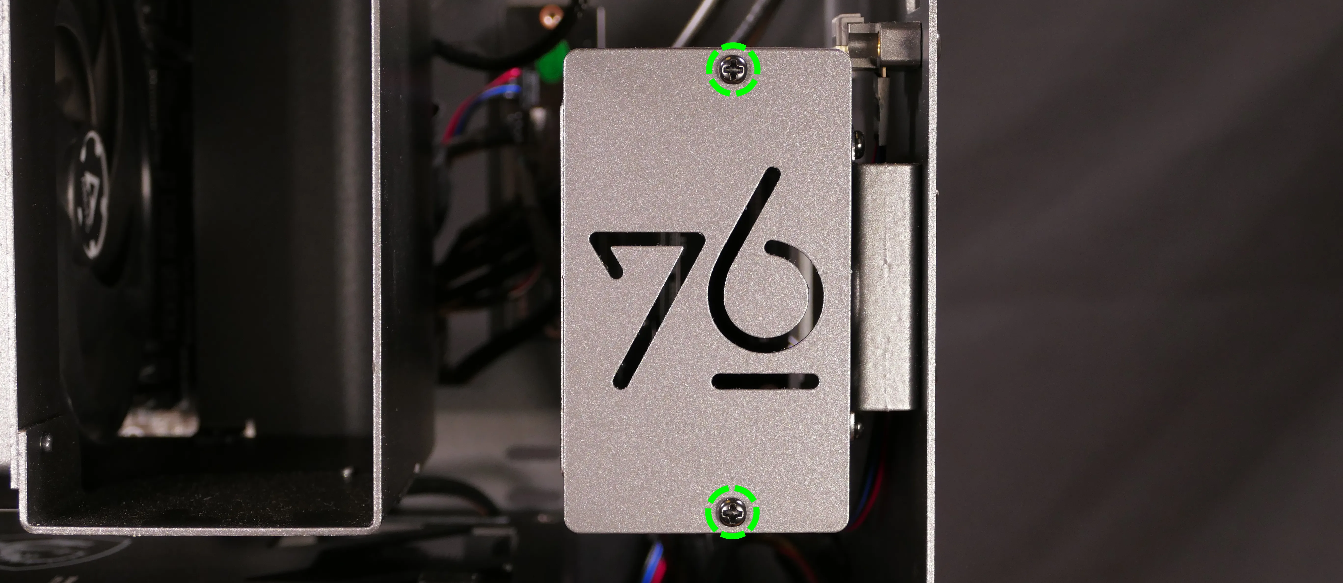
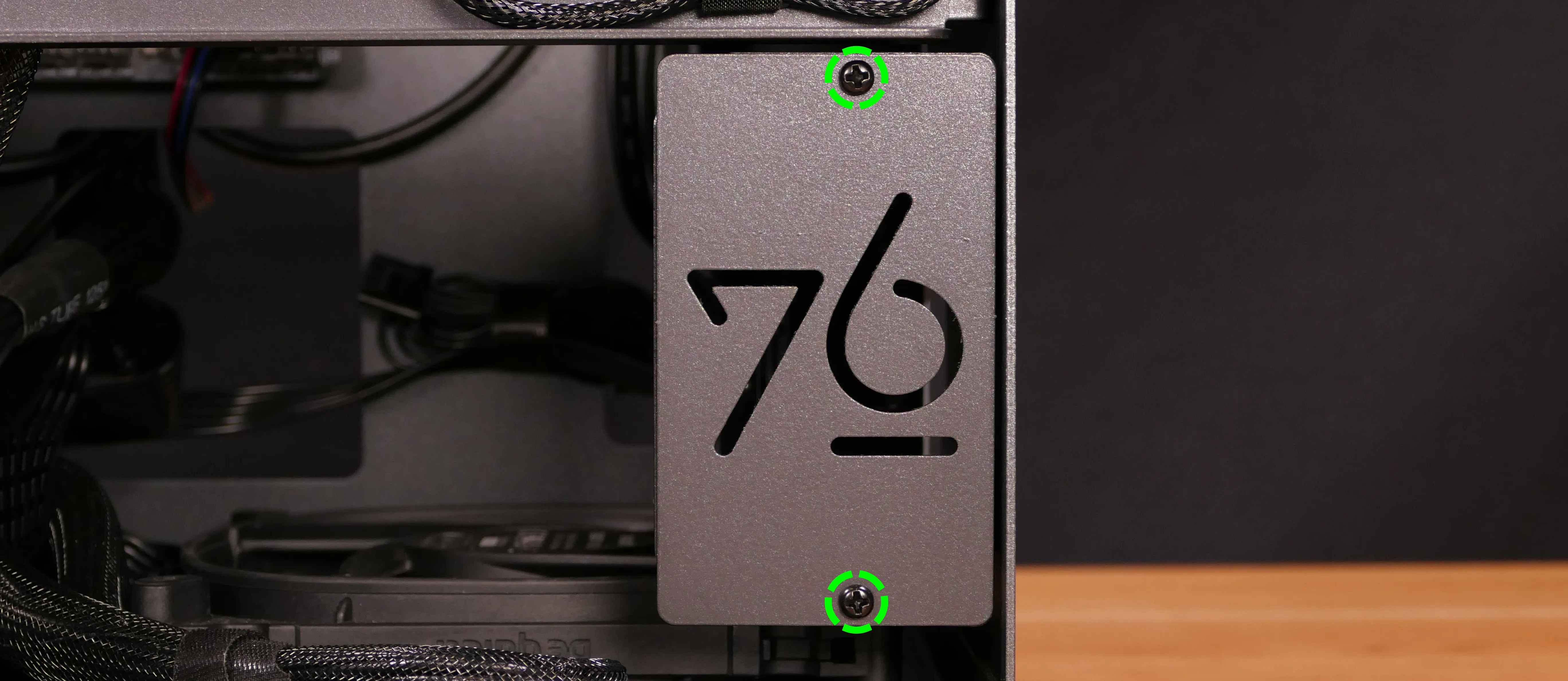
- If you are adding a new drive, pop out the black plastic ring on the top crossbar and slide out four screws (per drive).

- Insert four screws into each 2.5" storage drive you wish to install.
- Slide each 2.5" drive into one of the slots leading to the SATA backplane.

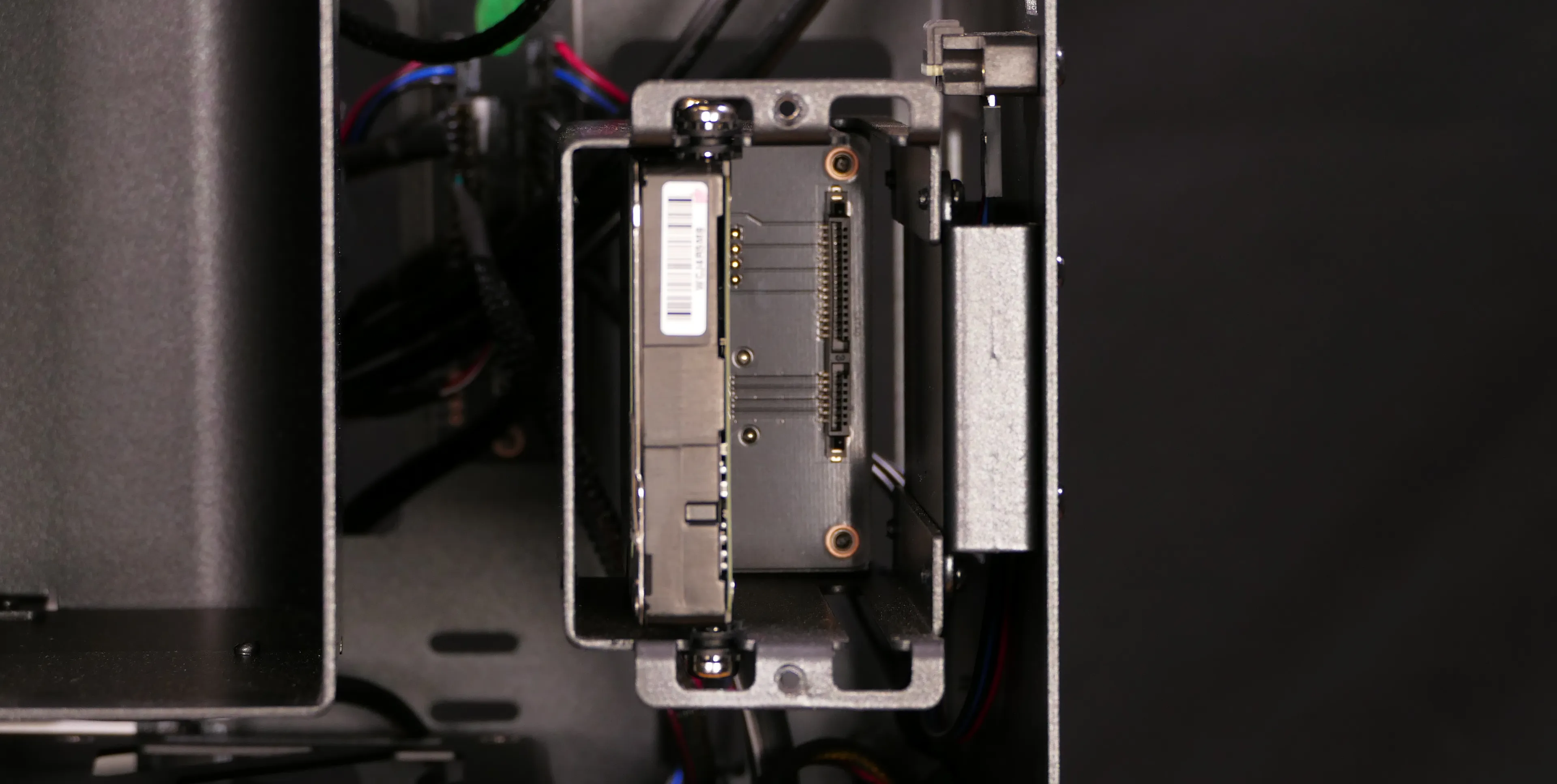
- Replace the black plastic screw ring and the 2.5" drive bay cover.
Removing the side brace:
The side brace provides a mounting point for the GPU brace finger(s), which help keep GPUs or other PCI Express cards in place during shipping. It also provides mounting points for up to two 120mm fans; one 120mm fan is offered as an optional add-on during factory configuration.
One or two GPU brace fingers may be installed by default, depending on the GPU model that shipped with the system. The GPU brace finger(s) are only required during shipping. The system can be run without this part if it does not fit an upgraded GPU.
Tools required: Cross-head (Phillips) screwdriver
Time estimate: 15 minutes
Difficulty: Easy ●
Steps to remove the side brace:
- Follow the steps above to remove the top case.
- Unscrew the four screws holding the side bracket in place (two on the front of the case, two on the back.)
- Take note of which screw holes the side brace is screwed into, which varies by GPU. In the below photos, the second-to-innermost set of screw holes is used.

- Pull the side brace out of the chassis. Unplug the side fan connector from the splitter board on the right side, if connected.
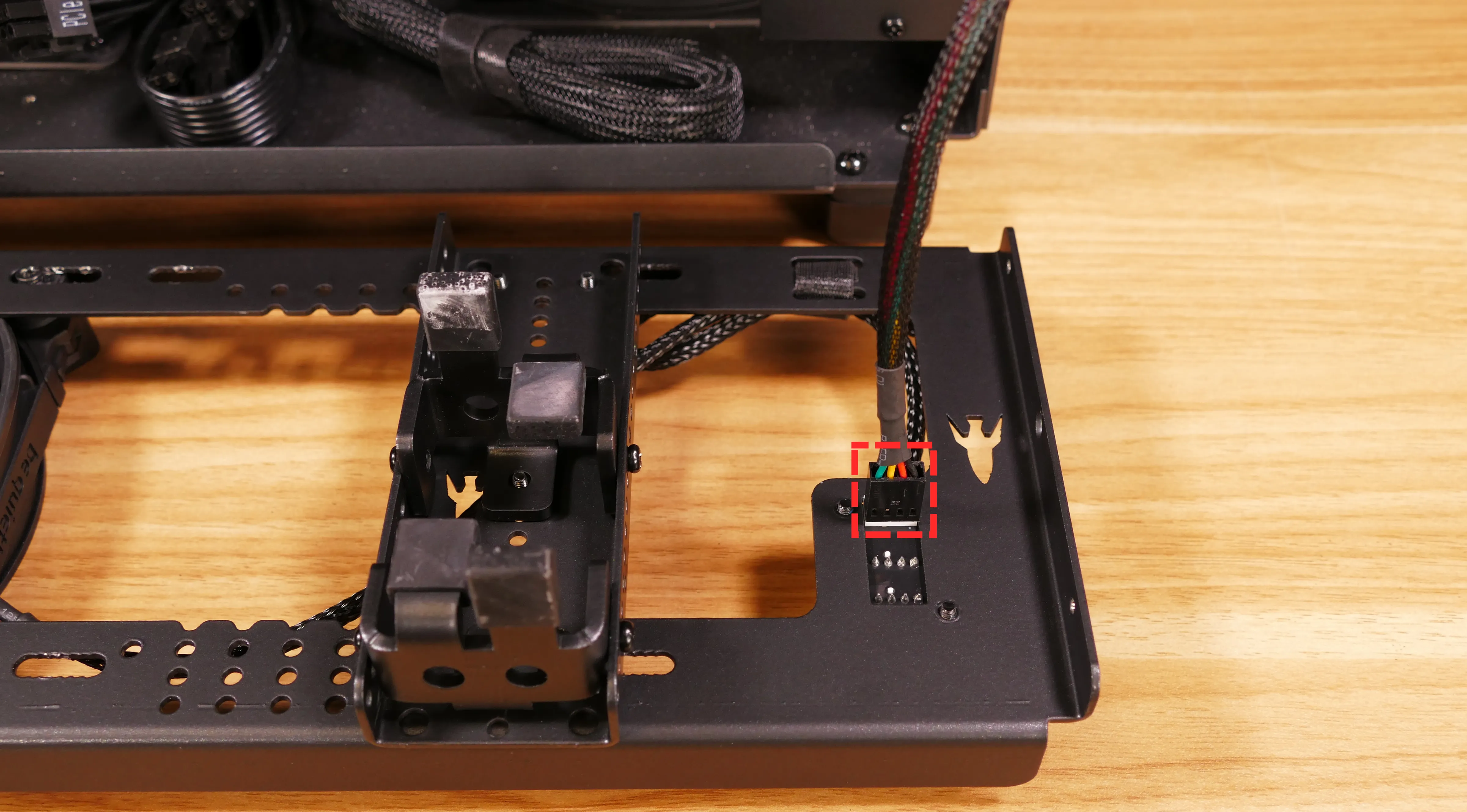
Steps to replace the optional side fan:
- Unplug the fan from the front of the splitter board on the right side of the brace (highlighted cyan below), then free the cable from the velcro loop (highlighted yellow).

- Unscrew the four screws holding the fan onto the side brace from the back.
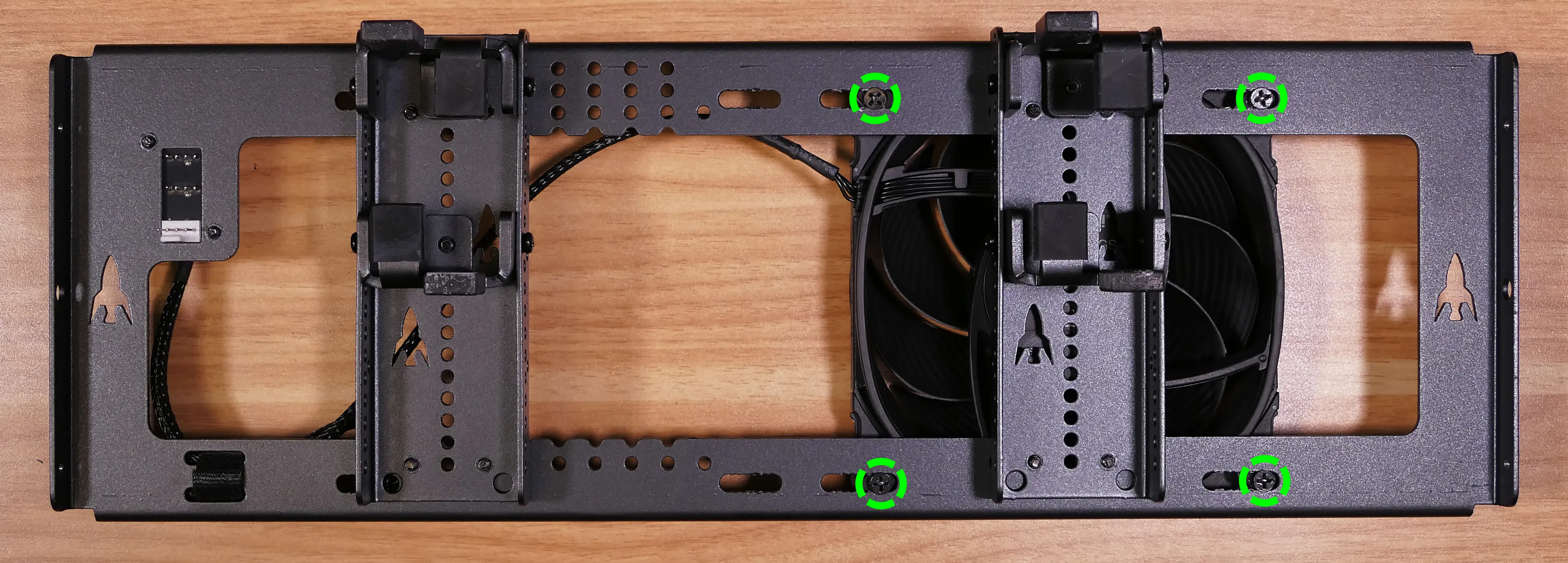
- When reinstalling the fan, the spinning side should face out of the chassis. The fan cable should be oriented towards the top-right, then secured with the velcro loop before reaching the splitter board.
Steps to adjust the GPU brace finger:
- Follow the steps above to remove the top case, remove the side brace, and remove the side fan (if installed over one of the brace fingers).
- To adjust a GPU brace finger's horizontal position, unscrew its four corner screws (highlighted green below), move the GPU brace finger's mounting bar, and reattach it in the desired position.
- Any vertical alignment screws overlapping the side brace (such as the ones highlighted cyan below) will also need to be removed.
- All screws highlighted below have flat heads to avoid interfering with the side fan.

- To adjust the GPU brace finger's vertical position, unscrew the three vertical adjustment screws, move the GPU brace finger, and reattach it in the desired position.
- The center screws (highlighted cyan) have flat heads to avoid interfering with the side fan.
- The side screws (highlighted yellow) have round heads.

Replacing the bottom case fan:
Thelio Major R5-N3 has one case-mounted intake fan on the bottom of the chassis.
Part numbers:
- The bottom case fan is a 140mm Be Quiet! Silent Wings 4 (model number
BQ SIW4-14025-MF-PWM).
Tools required: Cross-head (Phillips) screwdriver
Time estimate: 20 minutes
Difficulty: Medium ●
Steps to replace the bottom case fan:
- Follow the steps above to remove the top case.
- The side brace can optionally be removed to provide easier access to the fan and its cabling.
- Unplug the fan's cable from the Thelio Io daughterboard.
- The bottom case fan plugs into the
INTAKE FAN/FANOUT2port on the Thelio Io board. - When viewed from the access cutout on the front of the case, this connector is the lowest one with a white receptacle.
- The bottom case fan plugs into the

- Unscrew the four fan screws from the bottom of the machine.
- To avoid damaging other components, place the machine on its front side when working with the bottom surface.
- A soft surface such as a towel can optionally be used to protect the work surface and the machine.

- Remove the old fan from the case.
- When installing the fan, mount the components in the following order:
- Chassis
- Dust filter
- Acrylic spacer
- Fan
- The new fan's cable should be oriented towards the front-right corner of the case.
- The cable runs along the inner corner of the case.
- The slack is secured by a dedicated velcro loop (highlighted green below), then the cable passes through the velcro loop closest to the Thelio Io board (highlighted yellow).

Removing the CPU duct:
The CPU duct guides airflow through the CPU cooler. It covers the CPU and partially obstructs the RAM slots and top PCIe slot.
Tools required: Cross-head (Phillips) screwdriver
Time estimate: 7 minutes
Difficulty: Easy ●
Steps to remove the CPU duct:
- Follow the steps above to remove the top case and remove the side brace.
- Unplug the two fan connectors (highlighted yellow below) from the left splitter board in the front corner of the machine.
- The splitter board provides the same signal to both ports, so it doesn't matter which port each cable is plugged into. By default, the braided cable is on top.
- The non-braided Y cable can be left plugged in if you're not removing the CPU cooler-mounted fans.

- Unscrew the four back thumbscrews and two top crossbar screws holding the CPU duct in place.

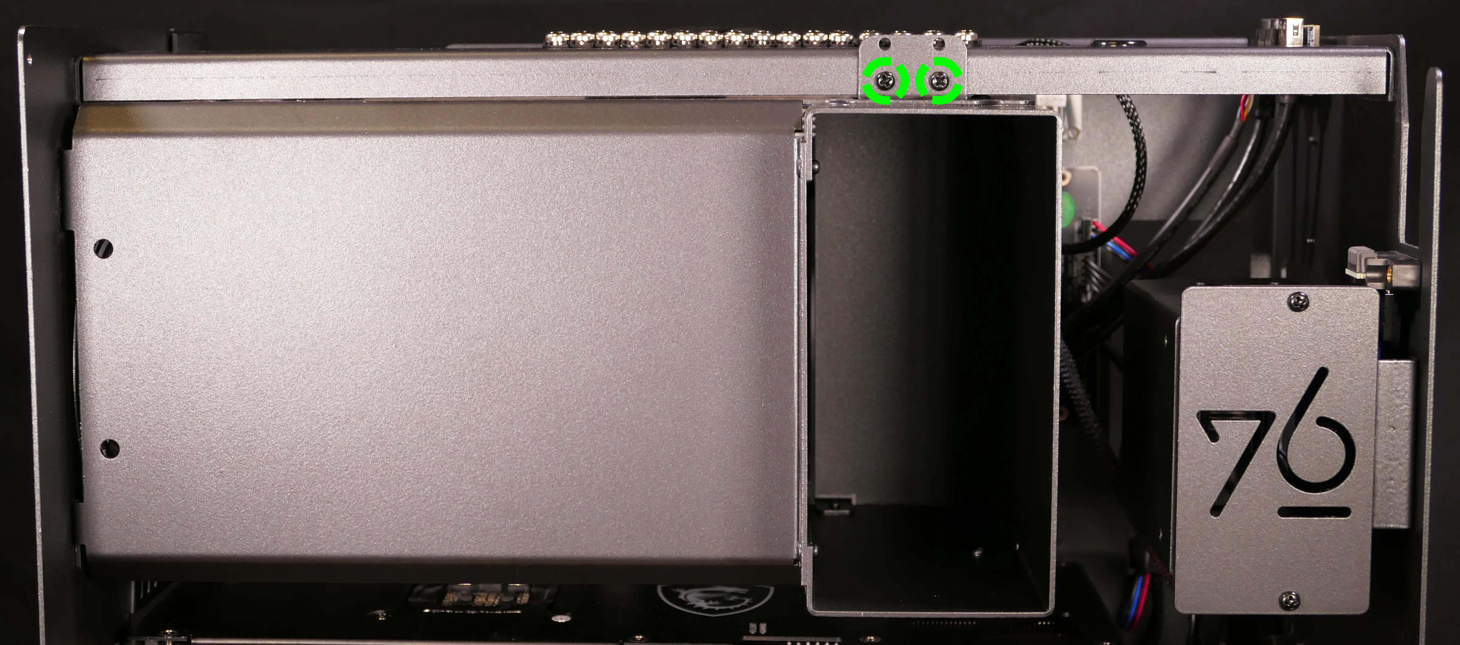
- Pull the CPU duct away from the machine.
Replacing the GPU:
Thelio Major ships with one dedicated GPU in the PCIe 5.0 x16 slot (top slot). GPUs greater than three slots tall may obstruct the lower PCIe slots.
Tools required: Cross-head (Phillips) screwdriver
Time estimate: 15 minutes
Difficulty: Medium ●
Steps to replace the GPU:
- Follow the steps above to remove the top case and remove the side brace.
- You can optionally remove the CPU duct for easier access to the PCIe slot and power cable latches.
- If you're removing a GPU, unplug the GPU power cable from the right side of the card. Hold down the latch on the connector while unplugging the cable.

- Unscrew the two back screws holding the PCIe bracket in place, and remove the PCIe bracket (or slide it into the rightmost position).

- Push back the latch on the motherboard to free the PCIe connection, then pull the card out of the slot.
- If the latch is difficult to reach between the GPU and the CPU heatsink, a long object (such as a screwdriver) can be used to push the latch.

- After inserting the new GPU into its slot, connect the power cable.
- Once the GPU is installed, replace the back PCIe bracket, CPU shroud (if necessary), side brace, and top case.
- The GPU brace finger may need to be adjusted before the side brace can be reinstalled.
Replacing the CMOS battery:
The CMOS battery supplies power to the system's CMOS chip. UEFI settings and the computer's hardware clock are stored on the CMOS. If your system doesn't boot, you can reset the CMOS to force a low-level hardware reset. If your clock is constantly resetting, it's likely your CMOS battery needs to be replaced.
Warning (ingestion hazard): Keep batteries out of reach of children. Death or serious injury can occur if ingested. If a battery is suspected to be swallowed or inserted inside any part of the body, seek immediate medical attention. In the US, you can also call the National Battery Ingestion Hotline for guidance: 1 (800) 498-8666
Part numbers:
- The CMOS battery is a standard KTS CR2032 battery.
Tools required: Cross-head (Phillips) screwdriver
Time estimate: 20 minutes
Difficulty: Medium ●
Steps to replace the CMOS battery:
- Follow the steps above to remove the top case and remove the side brace.
- Depending on the height of the GPU, it may help to also remove the GPU for easier access.
- Lift the CMOS battery against the spring at the top of the slot by prying from behind the opening at the bottom of the slot.
- A flat plastic tool can be used to aid lifting the battery.

- Pull the CMOS battery out of its slot.
- If you are resetting the CMOS, hold down the internal power button for 10 seconds to discharge any residual energy in the system.
- Replace the CMOS battery starting with the left side of the slot (opposite from the clip).
- The positive side of the battery (with text) should face outward.
- Replace the GPU, side brace, and top case.
Replacing the M.2 drives:
Thelio Major R5-N3 has four M.2 storage slots. All four slots are M-key and size 2280.
- Slots A, B, and C (the left three slots) support PCIe NVMe Gen 5.
- Slot D (the right slot) supports PCIe NVMe Gen 4.
Factory configurations only offer up to two M.2 SSDs (so at least two slots will be vacant by default).
Tools required: Cross-head (Phillips) screwdriver
Time estimate: 30 minutes
Difficulty: Medium ●
Steps to replace the M.2 drive:
- Follow the steps above to remove the top case, remove the CPU duct, and remove the GPU.
- Removing the GPU is optional to access the bottom two slots (Slots A and D).
- Remove the M.2 heatsink for the slot(s) you wish to access by pushing the semi-circular latch downward.
- The latch for the bottom heatsink will also release the M.2 drive from Slot D, if installed.
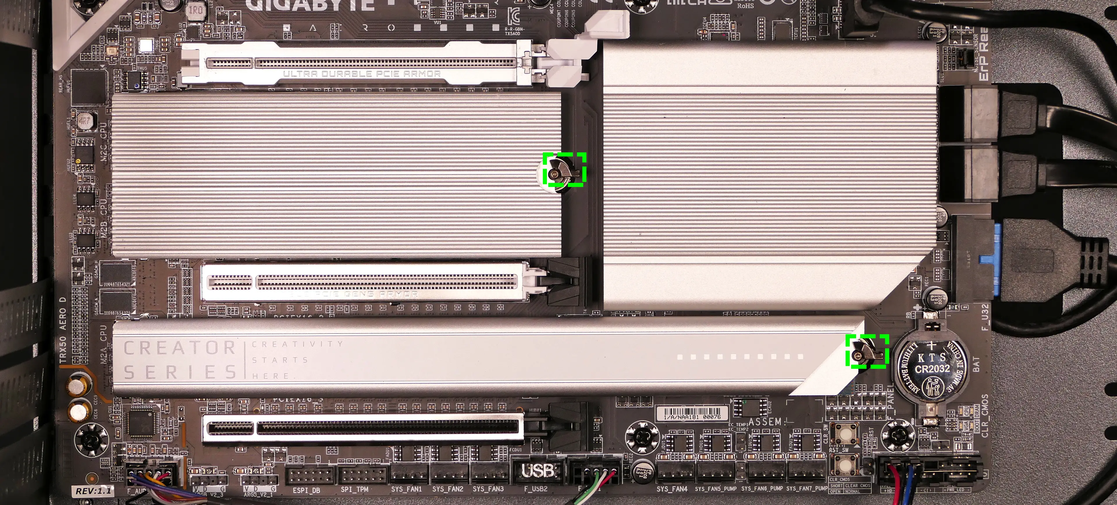
- To remove a drive from a slot, push the corresponding circular lever downwards to release it, then pull it out of the slot.

- To insert a drive into a slot, insert the connector, then push the opposite side down onto the circular tab until it clicks into place.
- For Slot D, be sure the drive clicks completely into the semi-circular tab-- the tab has notches for both the drive and the heatsink.
- Replace the M.2 heatsink(s).
- If you're using a slot for the first time, peel the protective plastic off of the corresponding thermal tape on the heatsink.
- In the below photo, the protective plastic has not yet been removed from the top strip of thermal tape.
- If you're using a slot for the first time, peel the protective plastic off of the corresponding thermal tape on the heatsink.
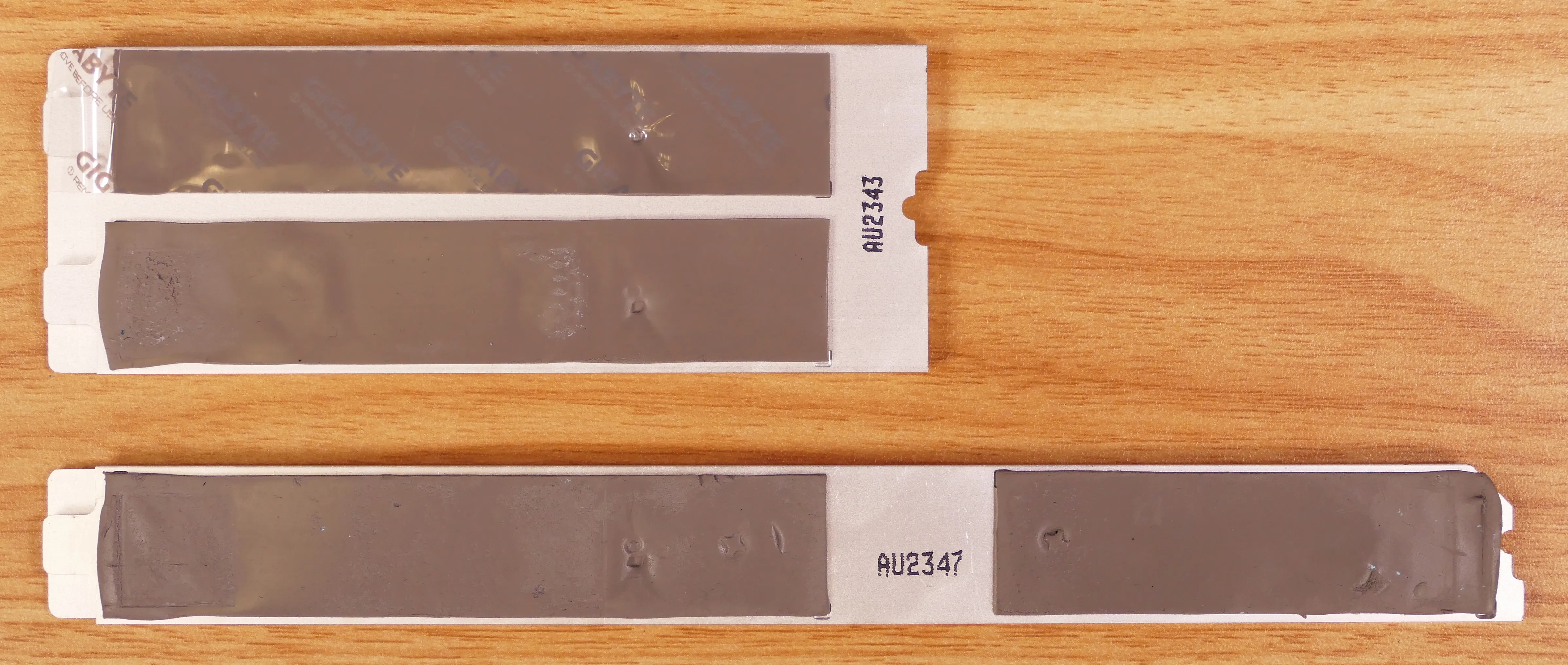
- Replace the GPU, CPU duct, side brace, and top case as applicable.
Replacing the CPU fans:
Thelio Major R5-N3 contains three 120mm CPU fans. The back fan is mounted on the CPU duct. The second and third fans are mounted on the front and back of the CPU heatsink.
Part numbers:
- The back (duct-mounted) CPU fan is a Be Quiet! Silent Wings 4 (
BQ SIW4-12025-MF-PWM). - The middle and front (heatsink-mounted) CPU fans are Arctic Freezer 4U fans.
- The heatsink-mounted fans are produced for the Arctic Freezer 4U-M CPU cooler, and it may not be possible to source them separately.
Tools required: Cross-head (Phillips) screwdriver
Time estimate: 25 minutes
Difficulty: Medium ●
Steps to replace the duct-mounted CPU fan:
- Follow the steps above to remove the top case and remove the CPU duct.
- Unscrew the four screws (two on each side) holding the fan bracket onto the duct.
- Depending on your screwdriver, removing the bracket from the duct may not be required, but it makes removal and installation of the fan much easier.

- Unscrew the four screws attaching the bracket to the fan.

- When reinstalling the fan into the CPU duct:
- The spinning side should face inward (towards the front of the chassis).
- When viewing the fan from the back of the computer (once the shroud is reinstalled), the cable should point up and to the right, and the label on the fan should be facing left.
- Overtightening the fan bracket's screws may cause fan noise; if the fan is creating excessive noise, try slightly loosening some of the screws.
Steps to replace the heatsink-mounted CPU fans:
- Follow the steps above to remove the top case and remove the CPU duct.
- You can optionally remove the side brace and remove the GPU for easier access.
- Disconnect the rear cooler fan from the front cooler fan's Y-cable, and unplug the front cooler fan's Y-cable from the splitter board (if it wasn't already unplugged while removing the CPU duct).
- The heatsink fan cable connection points are highlighted red below.

- Pull the fans (highlighted green above) directly out of the case, sliding them off the heatsink.

- When reinstalling the CPU heatsink fans, the fan with a normal cable goes on the back of the heatsink, while the fan with a Y-cable goes on the front.
Replacing the CPU cooler and CPU:
The CPU cooler dissipates heat from the CPU to the heatsink, where the CPU fans expel it from the system. Depending on your climate and the age of the machine, replacing the thermal paste between the CPU and the cooler/heatsink may help the system run cooler.
Part numbers:
- The CPU cooler is an Arctic Freezer 4U-M.
- The CPU uses an AMD sTR5 socket.
Tools required: Cross-head (Phillips) screwdriver, AMD Threadripper torque tool or compatible 1.5 Nm (13.275 in-lb) torque 3.95mm six-point star (Torx 20) screwdriver, thermal paste
Time estimate: 45 minutes
Difficulty: High ●
Steps to remove the CPU cooler/thermal paste:
- Follow the steps above to remove the top case, remove the side brace, remove the CPU duct, remove the GPU, and remove the heatsink-mounted CPU fans.
- While holding the CPU cooler in place so it doesn't fall, loosen the screws to the left and right of the CPU cooler.
- The two screws on the left side use the outer holes.
- The two screws on the right side use the inner holes.

- Lower the cooler away from the CPU.
- Using a paper towel, clean the existing thermal paste off of the heatsink and CPU.
- Due to the design of the heatsink, some thermal paste may remain between the heatsink pipes. Only the flat section of the pipes that makes contact with the CPU needs to be cleaned.
- You may also use a small amount of rubbing alcohol if the old paste is dried or difficult to remove.

Steps to replace the CPU:
- Place the computer on its side so the motherboard is facing up.
- Using the AMD Threadripper torque screwdriver (or a compatible T20 screwdriver), loosen the three CPU bracket Torx screws in reverse order of the printed numbers (starting with #3).
- The screws are held captive and will not come out of the bracket.
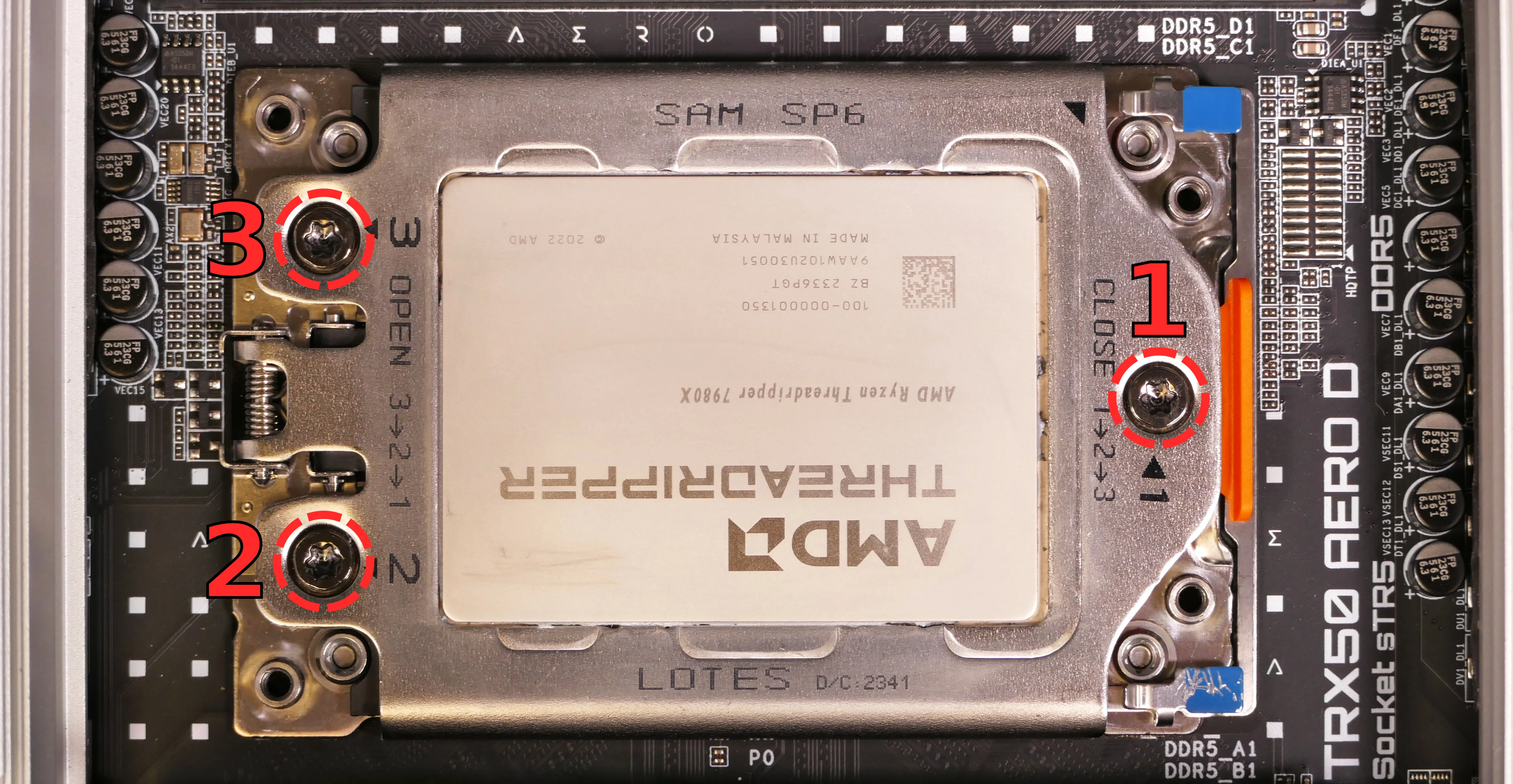
- The CPU bracket cover will spring up when all screws are fully loosened.
- If the bracket cover only partially opens, you may need to loosen screws #2 and/or #3 more.
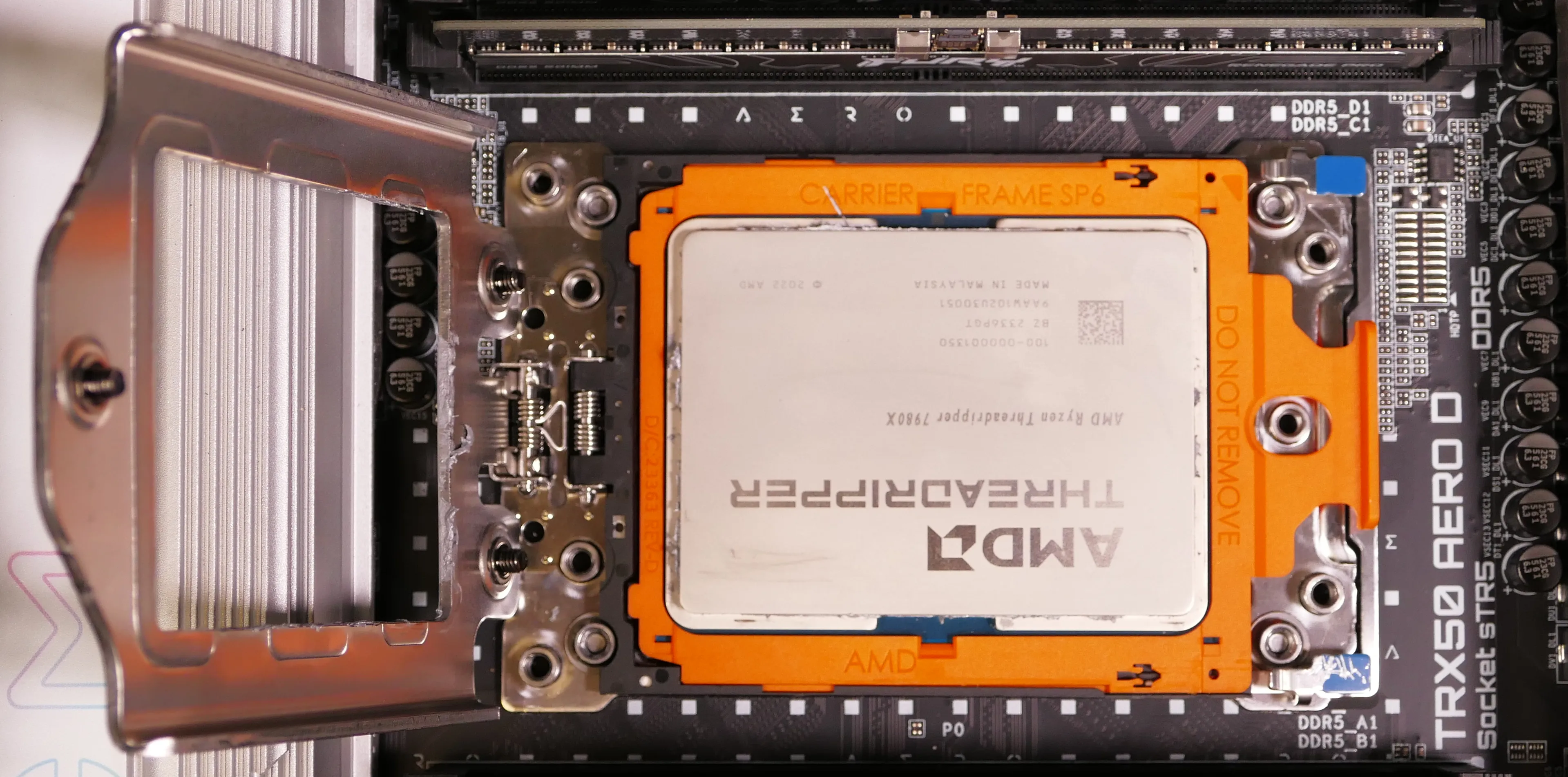
- Using the blue corner tabs (visible above), flip the orange CPU carrier frame up and away from the CPU socket.
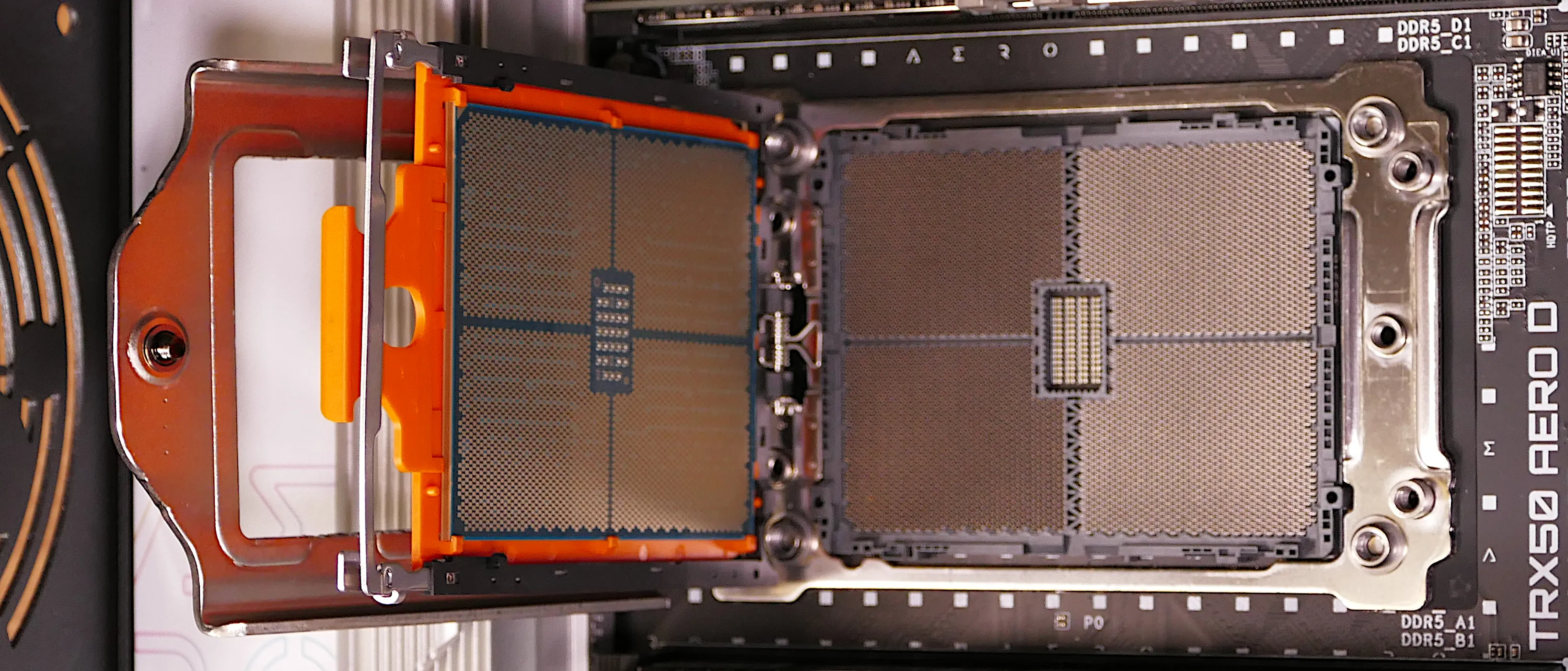
- Slide the CPU carrier tray out of the CPU bracket.
- Be careful not to bend any of the gold pins on the CPU socket, and do not touch the gold pads on the CPU.
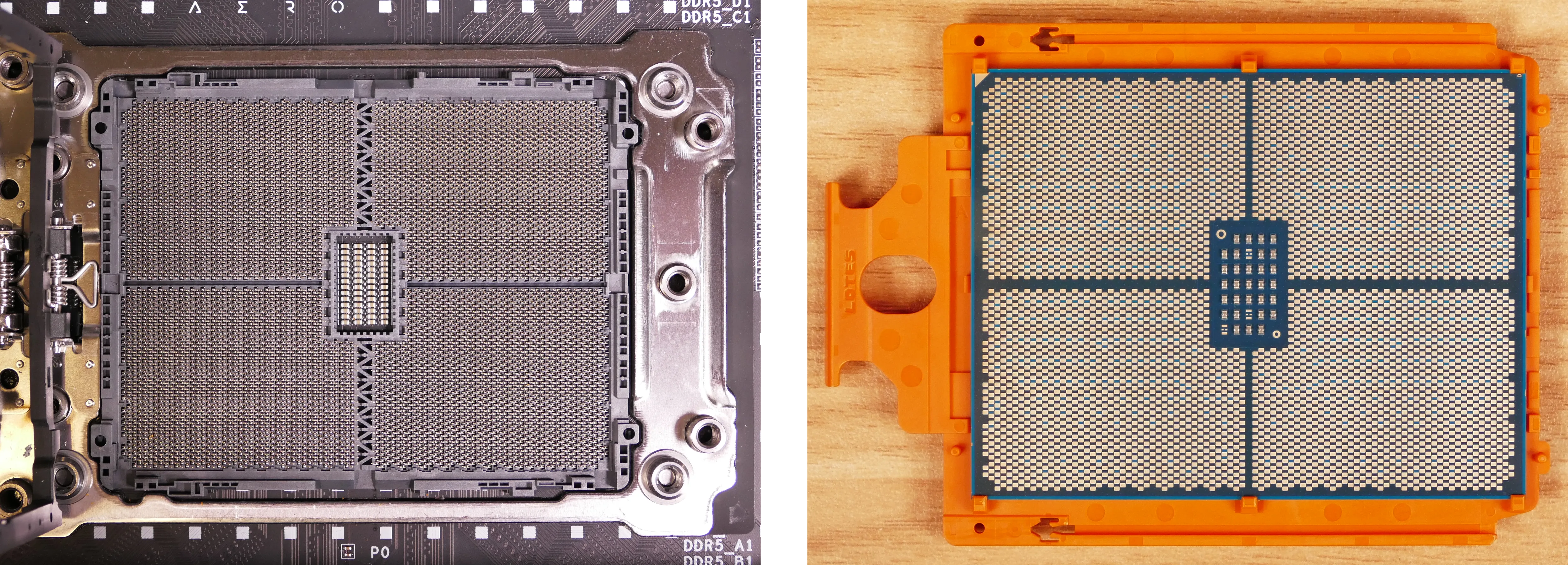
- Slide the new CPU's carrier tray into the CPU bracket.
- AMD Threadripper CPUs come with carrier trays, so removing the CPU from the tray is generally not necessary.
- Flip the CPU bracket back down onto the socket, gently pressing the blue tabs to seat the CPU carrier tray onto the motherboard.
- Flip the CPU bracket cover back down.
- Screw the three Torx screws back into place in order of the printed numbers (starting with #1).
- The AMD Threadripper-branded tool applies 1.5 Nm of torque. When the screw is tight enough, it will give way.
- If you're using a different screwdriver, use a torque tool to apply approximately the same amount of torque (1.5 Nm, or ~13.275 in-lb).
- If you're using a screwdriver without a torque tool, try to tighten all three screws evenly. After re-assembling the computer, run a RAM test to ensure the CPU is secured with the correct amount of force.
Steps to install the thermal paste/CPU cooler:
- Draw an
Xshape of thermal paste onto the CPU.

- Place the CPU cooler onto the CPU; while holding it in place, screw its vertical mounting bar into the horizontal mounting brackets.
- The cooler should be oriented so the Thermalright logos are on the bottom.
- Insert each screw partially, then finish tightening both.
- Set the computer upright, then reinstall the cooler-mounted CPU fan, CPU duct, GPU, side brace, and top case.
Replacing the RAM:
Thelio Major R5-N3 supports up to 512GB (4x128GB) of RAM. The RAM sticks are DDR5 ECC DIMMs running at a speed of 5600 MHz.
If you've purchased new RAM, need to replace your RAM, or are reseating your RAM, follow these steps.
Tools required: Cross-head (Phillips) screwdriver
Time estimate: 15 minutes
Difficulty: Medium ●
Steps to replace the RAM:
- Follow the steps above to remove the top case, remove the CPU duct, and remove the CPU cooler.
- Removing the CPU cooler is optional, but is recommended to provide easier access to the RAM slots.
- Replacing the thermal paste is recommended if the CPU cooler is removed.
- To remove an existing RAM stick, flip the left and right latches away from the stick, then pull the stick out of the slot.

- Make sure the tabs on the left and right of the slot are open (pulled away from the slot), then insert the new RAM (or re-seat the existing RAM) into the slot.
- The RAM stick will only fit in one direction. The larger group of pins goes on the left.
- Use the following guide for placement of the RAM sticks:

- Replace the top case.
Replacing the power supply:
The power supply unit (PSU) can be replaced with another unit of the same model.
Part numbers:
- The default PSU in units shipped after October 2025 is the XPG Core Shift II (1200W).
- The default PSU in units shipped from July 2024 until October 2025 is the XPG Core Reactor II (1000W).
- The default PSU in units shipped before July 2024 is the Be Quiet! Pure Power 12 M 1000W (L12-M-1000W).
Tools required: Cross-head (Phillips) screwdriver
Time estimate: 45 minutes
Difficulty: Medium ●
Steps to replace the power supply:
- Follow the steps above to remove the top case, remove the side brace, and unplug the GPU (if installed).
- Unscrew and remove the PSU bracket.
- One screw is located on the opposite side of the case.


- Unscrew the power supply's four screws from the back of the chassis.

- Unplug all of the modular cabling from the back of the PSU.

- Remove/replace the power supply.
- The replacement PSU should be installed with the fan facing the bottom of the case.
- Place the PSU on the rubber post and hold it against the screwholes in the back of the case while attaching it.
- Connect the power cables to the new power supply and GPU (if installed), then reinstall the PSU brace, side brace, and top case.
Replacing the Thelio Io board:
Named after Jupiter's moon Io, the Thelio Io daughterboard handles the front power button and fan control. If the Thelio Io board becomes defective, it can be replaced using the instructions below.
Part numbers:
- Thelio Major R5-N3 uses Thelio Io version 2 (PCB revision thelio_io_2.3).
Tools required: Cross-head (Phillips) screwdriver
Time estimate: 30 minutes
Difficulty: High ●
Steps to replace the Thelio Io board:
- Follow the steps above to remove the top case.
- The CPU duct and side brace can optionally be removed to provide easier access to the cabling.
- Use the cutout on the front of the chassis to unplug all cabling from the Thelio Io board.
- The second-from-top connector (
POWER1) requires pulling the white tab while unplugging. - The bottommost connector (
USB) requires holding the black tab while unplugging.
- The second-from-top connector (

- Unscrew the two screws holding the daughterboard on from the right side of the chassis.

- Screw in the new Thelio Io board and reconnect the wiring.
Thelio Io wiring guide:

-
When wiring the Thelio Io board, refer to the port labels and the following guide.
FANOUT1/CPU FAN- to the fan splitter closest to the CPU fans.FANOUT4/AUX FAN- to the auxiliary fan splitter (next to the CPU fan splitter).FANOUT2/INTAKE FAN- to the bottom case fan.FANOUT3/GPU FAN- to the side brace fan splitter.- May be disconnected by default if no side fan (GPU cooling intake fan) is ordered as factory configuration.
FANIN1/MOTHERBOARD FAN INPUT- to theCPU_FANheader on the right side of the motherboard (behind the CPU shroud), highlighted cyan below.

POWER1/POWER INPUT- to the power supply (via 4-pin Molex connector).- The white plastic clip needs to be held away from the connector to unplug this cable from the Thelio Io board.
PFP1/FRONT PANEL- to the power button receptacle on the front panel.- On the Thelio Io board, the wire color order (from top to bottom) is red, black, blue, black.
- On the power button receptacle, the wire color order (from left to right) is red, black, blue, black.
PMB1/MOTHERBOARD- to the first four pins of theF_PANELheader at the bottom right of the motherboard, highlighted green below.- On the Thelio Io board, the wire color order (from top to bottom) is red, black, blue, black.
- On the motherboard, the wire color order (from left to right) is red, black, blue, black.
USB- to theF_USB1header on the bottom edge of the motherboard, highlighted yellow below.- A small clip needs to be held down to unplug this cable from the Thelio Io board.

Replacing the SATA backplanes:
The SATA backplanes provide four 2.5" SATA data and power connectors (two per backplane) for the 2.5" drive cage.
Part numbers:
- The part number and version for the SATA backplane is thelio-io-sata_2.2.
Tools required: Cross-head (Phillips) screwdriver
Time estimate: 30 minutes
Difficulty: Medium ●
Steps to replace the SATA backplane:
- Follow the steps above to remove the top case, then remove the 2.5" drive cage cover and all 2.5" SATA drives in front of the backplane you are replacing.
- The CPU duct, side brace, and GPU can optionally be removed to provide easier access to the cabling.
- Use the cutouts on the front right corner of the chassis to unplug the 4-pin Berg power connector (highlighted cyan below) and the two SATA data cables (highlighted green below) from the SATA backplane you're replacing.
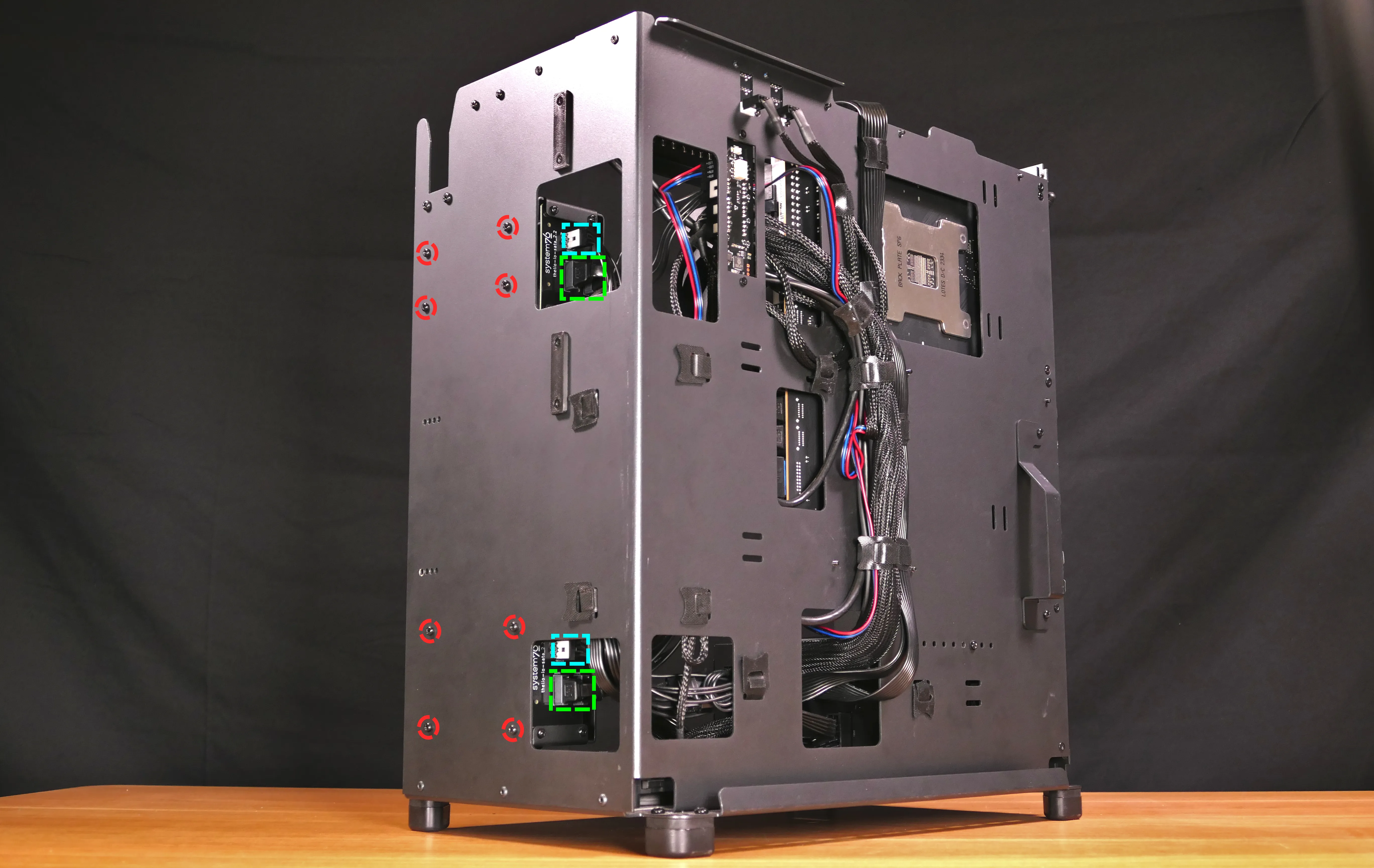
- Unscrew the four screws holding the drive cage onto the chassis (highlighted red above), then remove the drive cage from the chassis.
- The top drive cage contains an additional bracket to adapt the screw placement to the chassis, which does not need to be removed.
- Unscrew the four SATA backplane screws from the drive cage, then push the SATA backplane out through the front of the drive cage.

- Place the new SATA backplane into the drive cage and secure it with the four SATA backplane screws, then reinstall the drive cage.
- Plug the 4-pin Berg power connector and SATA data cables into the SATA backplane.
- The order of the SATA data cables shouldn't matter as long as your operating system and software is configured to address disks by UUID (e.g.
/dev/disk/by-id/...) instead of by letter (e.g./dev/sd_). - By default, the ports connect as follows:
- Top board
DATA0connects to motherboardSATA3 0(front). - Top board
DATA1connects to motherboardSATA3 1(back). - Bottom board
DATA0connects to motherboardSATA3 2(front). - Bottom board
DATA1connects to motherboardSATA3 3(back).
- Top board
- The order of the SATA data cables shouldn't matter as long as your operating system and software is configured to address disks by UUID (e.g.
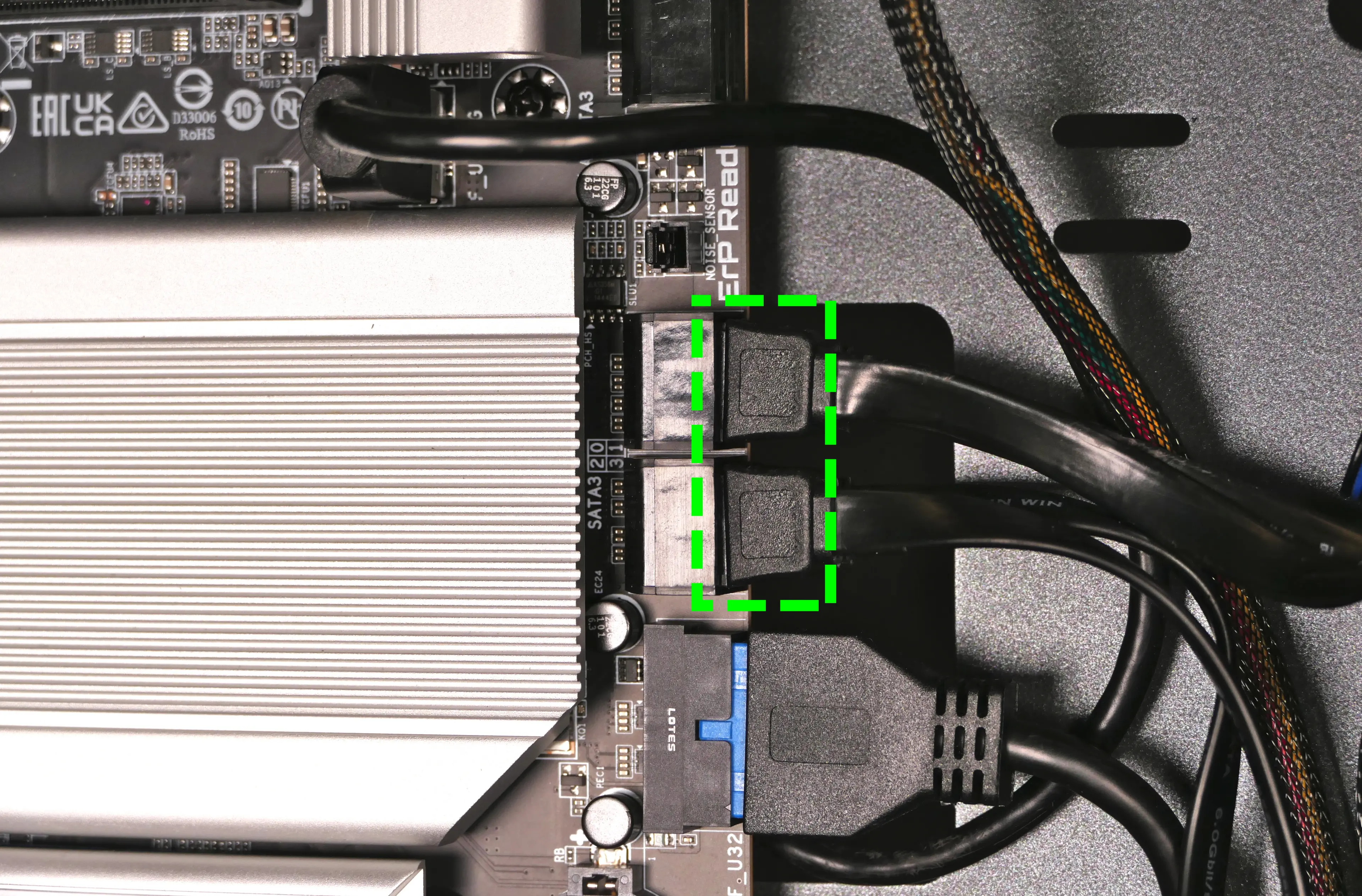
- Reinstall the GPU, side brace, and CPU shroud (if necessary), along with any 2.5" drives that were removed, the 2.5" drive cage cover(s), and the top case.
Replacing the top I/O:
Thelio Major R5-N3 includes a top I/O module providing audio and USB ports. If the top ports are damanged or become defective, they can be replaced using the steps below.
Part numbers:
- The top I/O module's part number is
MYS7523 Rev. 4.0.
Tools required: Cross-head (Phillips) screwdriver
Time estimate: 30 minutes
Difficulty: Medium ●
Steps to replace the top I/O:
- Follow the steps above to remove the top case.
- You can optionally remove the CPU duct and remove the side brace for easier access to the wiring. Depending on the size of your GPU, you may also need to remove the GPU.
- Unplug the
F_AUDIOheader at the bottom-left corner of the motherboard.

- Unplug the
F_U32OGheader (highlighted green below) andF_U32header (highlighted cyan below) on the right side of the motherboard.
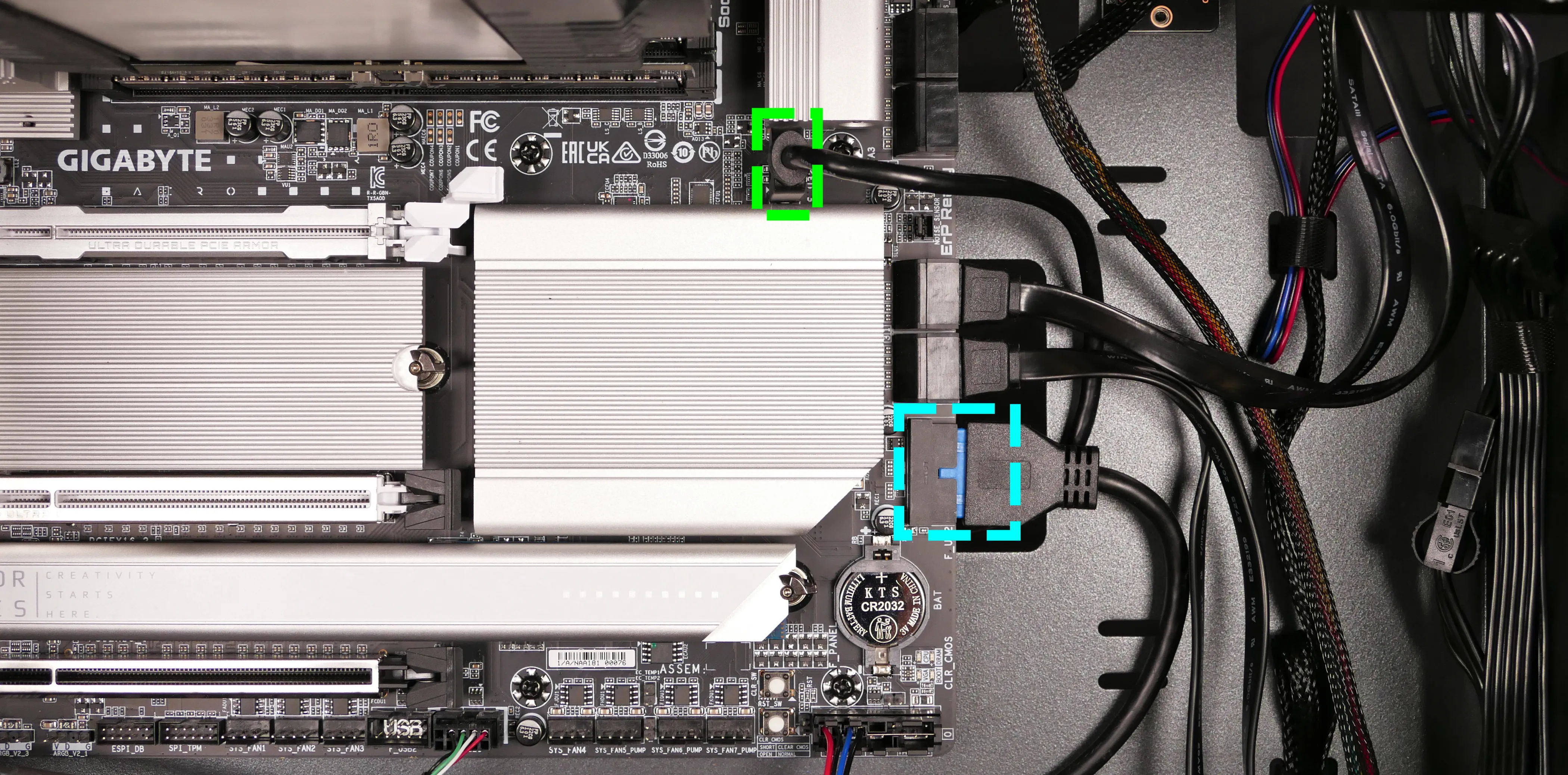
- Unscrew the two front screws holding the top I/O board onto the chassis.
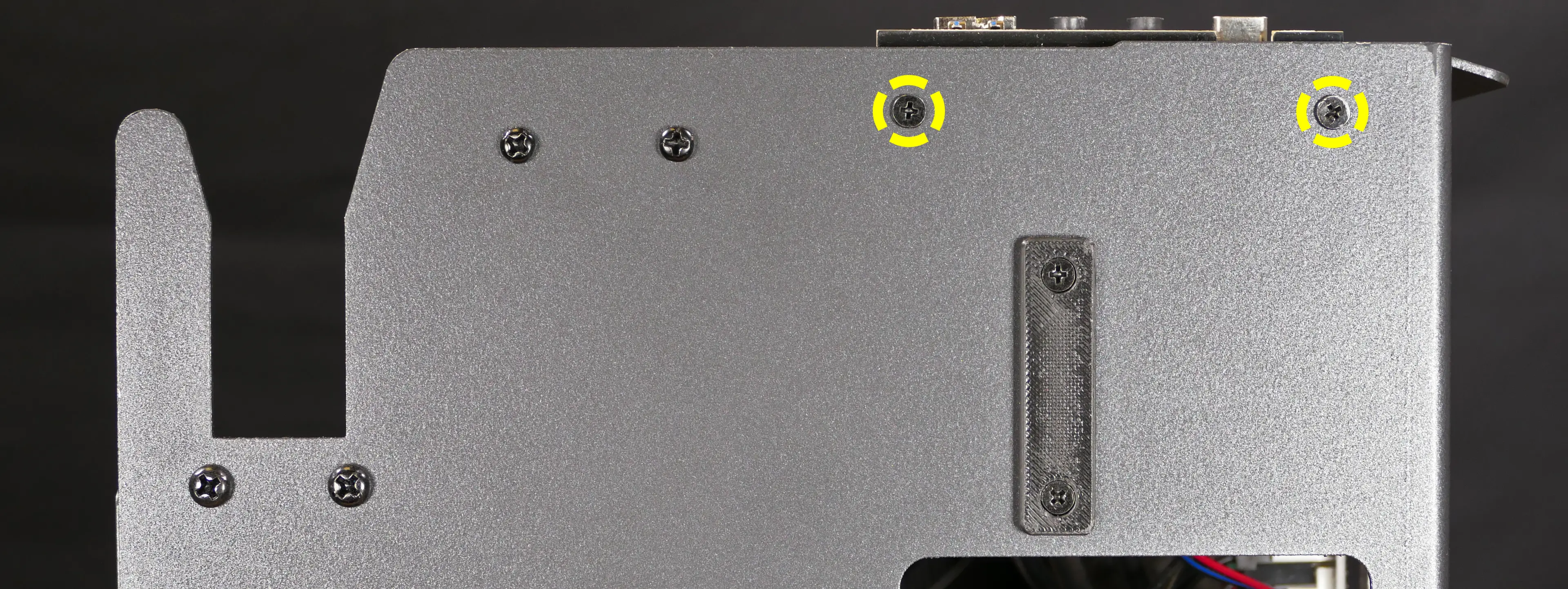
- Remove the top I/O board from the system.
- Insert the new top I/O board into the system and screw it into place.
- Reconnect the audio and USB headers.
- Replace the side brace (if necessary), CPU shroud, and top case.
Troubleshooting the power button:
If the front power button doesn't power the machine on or doesn't light up when the system is powered on, try the following troubleshooting steps:
- Ensure the system powers on normally using the internal power button.
- Reseat the front power button to ensure it's making proper contact.
- Check the wiring for the front power button.
- Replace the front power button, if necessary.
Tools required: Cross-head (Phillips) screwdriver (optional)
Time estimate: 20 minutes
Difficulty: Medium ●
Steps to power the machine on using the internal power button:
- Follow the steps above to remove the top case.
- Ensure the system is plugged into power, and the power supply switch is in the 1 (On) position.
- Push the small button labeled
POWERon the Thelio Io board.- The white LED to the left of the button lights up to indicate when the system is powered on (and pulses when the system is suspended).

- If the Thelio Io
POWERbutton powers the machine on and the LED lights up, then the issue is either the front power button or its connection to the Thelio Io board. Check the front power button wiring. - If the Thelio Io
POWERbutton and/or LED does not work, then the issue is either the Thelio Io board or its connection to the motherboard. Check the wiring between the Thelio Io board and the motherboard.
Steps to check the front power button wiring:
- Follow the steps above to remove the top case.
- On the back of the power button, the four pins should be connected to the four-wire connector as follows:

- On the front power button receptacle, the four-pin connector should have the red wire on the left and the black wire on the right (when viewed from the back of the computer.)
- If necessary, you can remove the top 2.5" drive cage for easier access to the power button receptacle's connector.

- The front power button receptacle should plug into the
PFP1port on the Thelio Io board, with the red wire on the top (see the Thelio Io wiring guide.)
Steps to replace the power button:
- Follow the steps above to remove the top case.
- Follow the instructions in the Replace the Thelio Power Button support article.
Thelio Massive (thelio-massive-b1.2)
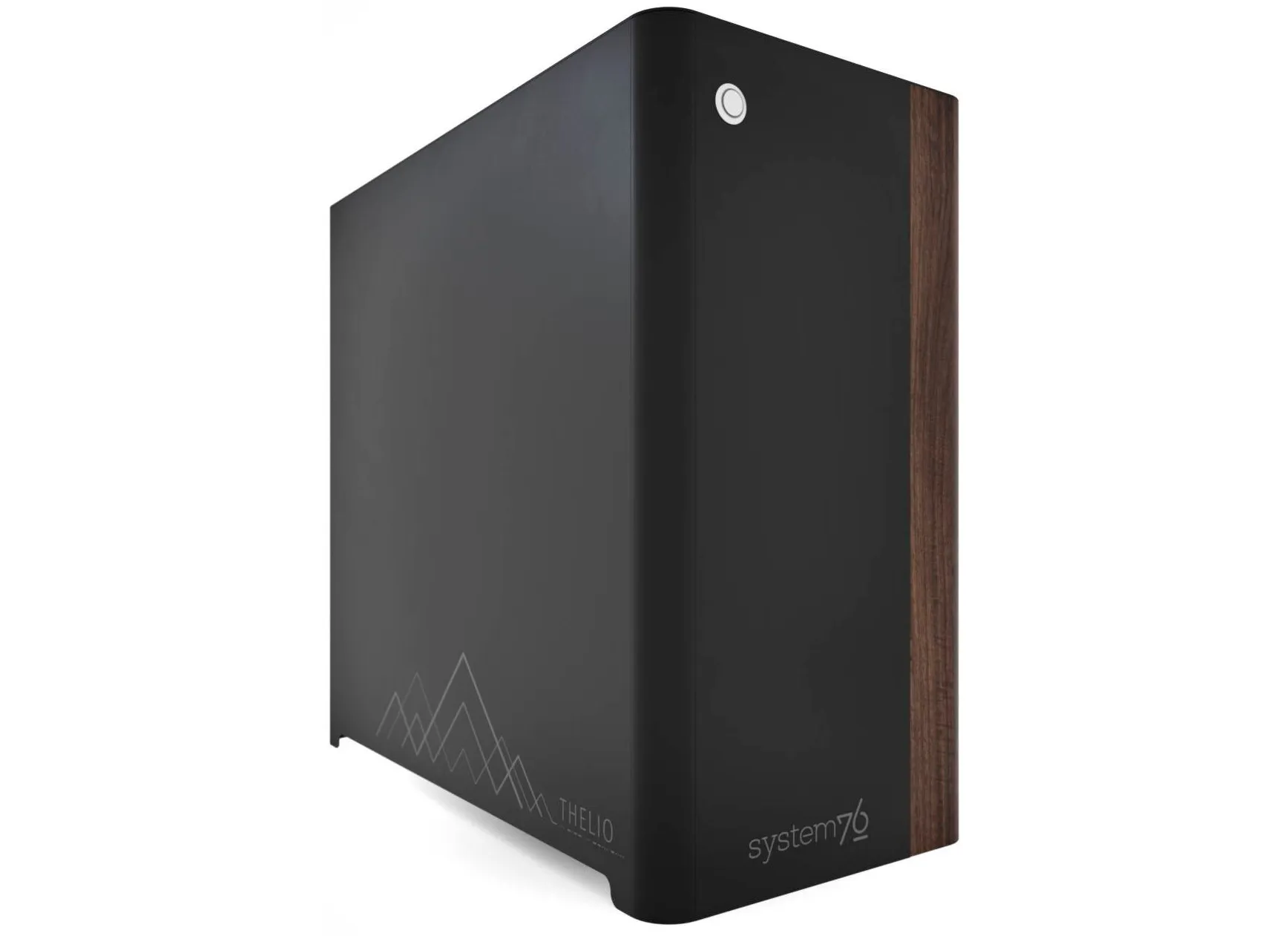
The System76 Thelio Massive is a desktop with the following specifications:
- CPU options
- Up to two matching CPUs
- Supports 2nd Gen Intel Xeon Scalable processors
- Motherboard
- ASUS WS C621E SAGE running System76 Firmware (non-open)
- Intel C621 chipset
- Daughterboard
- Thelio Io board running open-source firmware
- GPU options
- Up to four GPUs (PCIe 3.0 x16)
- GPU size:
- Internal clearance: 544.90mm
- Recommended maximum length: 534.90mm
- Tested with the following GPUs:
- AMD Radeon RX 550
- HDMI 2.0b, DisplayPort 1.4, Dual-Link DVI-D
- AMD Radeon RX 5700 XT
- HDMI 2.0b, 3x DisplayPort 1.4
- NVIDIA GeForce RTX 2060 Super
- HDMI 2.0b, 2x DisplayPort 1.4, Dual-Link DVI-D, DisplayPort over USB-C (VirtualLink)
- NVIDIA GeForce RTX 2070 Super
- HDMI 2.0b, 3x DisplayPort 1.4, DisplayPort over USB-C (VirtualLink)
- NVIDIA GeForce RTX 2080 Super
- HDMI 2.0b, 3x DisplayPort 1.4, DisplayPort over USB-C (VirtualLink)
- NVIDIA GeForce RTX 2080 Ti
- HDMI 2.0b, 3x DisplayPort 1.4, DisplayPort over USB-C (VirtualLink)
- NVIDIA Titan RTX
- HDMI 2.0b, 3x DisplayPort 1.4, DisplayPort over USB-C (VirtualLink)
- AMD Radeon RX 550
- Memory
- Up to 1536GB (12x128GB) six-channel Registered ECC DDR4 DIMMs @ 2933 MHz
- Up to 768GB (6x128GB) per CPU
- Networking
- 2x Gigabit Ethernet (Intel I210-AT)
- Optional Gigabyte Wireless-AC (a/b/g/n/ac) with Bluetooth
- Power
- EVGA SuperNOVA 1600W G2 80+ Gold Certified PSU
- C19 power cord
- Sound
- 3.5mm line out, line in, microphone jacks
- Optical S/PDIF out
- Up to 7.1-channel audio output
- Realtek ALC S1220A audio chipset
- HDMI, DisplayPort, USB-C DisplayPort audio (depending on GPU)
- Storage
- 1x M.2 (PCIe NVMe or SATA)
- 8x 2.5" SATA
- 4x 2.5" U.2 (NVMe) SAS
- SD card reader
- USB
- 1x USB 3.1 Gen 2 Type-C
- 1x USB 3.1 Gen 2 Type-A
- 4x USB 3.1 Gen 1 Type-A
- 2x USB 2.0 Type-A
- Dimensions
- 49.2cm x 26.2cm x 52.7cm
Thelio Massive (External Overview)
Back side overview:

Audio Port Guide:
- Green: Line Out / Front Speaker Out
- Pink: Mic In
- Light Blue: Line In / Side Speaker Out
- Orange: Center/Subwoofer Out
- Black: Rear Speaker Out
- White (square): S/PDIF Digital Out
Power Switch Guide:
- 1: On
- 0: Off
Thelio Massive (Internal Overview)
Side overview:
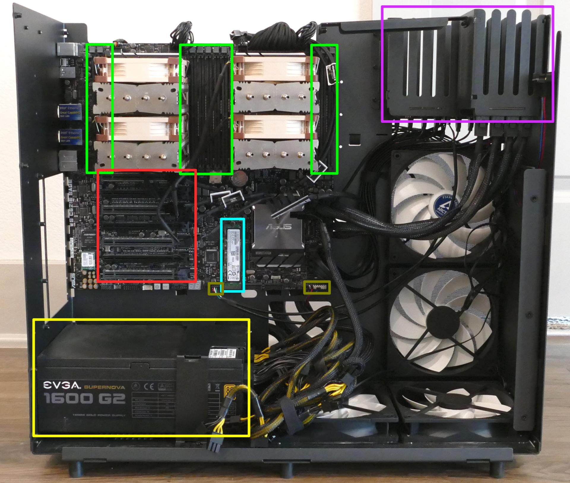
- RAM slots are highlighted in green
- PCIe slots are highlighted in red
- M.2 SSD is highlighted in cyan
- Power supply is highlighted in yellow
- 2.5" drive slots are highlighted in purple
- Thelio-IO to motherboard connections are highlighted in olive
PCIe slot guide:
From top to bottom:
- PCIe Gen 3 x16 slot (GPU 4)
- Only available if two CPUs are installed
- PCIe Gen 3 x8 slot
- Only available if two CPUs are installed
- PCIe Gen 3 x16 slot (GPU 1)
- Runs at x8 if slot 4 (immediately below) is also in use
- PCIe Gen 3 x8 slot
- PCIe Gen 3 x16 slot (GPU 2)
- PCIe Gen 3 x8 slot
- Only available if two CPUs are installed
- PCIe Gen 3 x16 slot (GPU 3)
- Only available if two CPUs are installed
See the repairs page for GPU installation instructions, including recommended GPU placement.
Top overview:
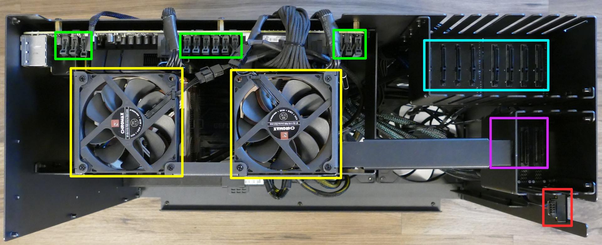
- RAM slot clips are highlighted in green
- Top exhaust fans are highlighted in yellow
- SATA ports are highlighted in cyan
- SAS (U.2) ports are highlighted in purple
- Power button receptacle is highlighted in red
Thelio Massive (Parts & Repairs)
Many components in your Thelio Massive can be upgraded or replaced as necessary. Power the machine off, switch off the power supply, and unplug all peripherals before working with any internal components. Then, follow these step-by-step guides for instructions:
- Removing the top case
- Removing the inner partition
- Adding/removing 2.5" storage drives
- Replacing the case fans
- Replacing a GPU
- Replacing the M.2 drive
- Removing the CPU duct
- Replacing the RAM
- Replacing the CPU fans
- Replacing the CPU cooler
- Replacing the CPU/thermal paste
- Replacing the top exhaust fans
- Troubleshooting the power button
- Troubleshooting the Thelio-IO USB connection
Removing the top case:
The top case can be removed to access the internal components.
Tools required: Cross-head (Phillips) screwdriver (optional)
Time estimate: 2 minutes
Difficulty: Easy ●
Steps to remove the top case:
- Remove the eight outer screws holding the top case onto the machine.
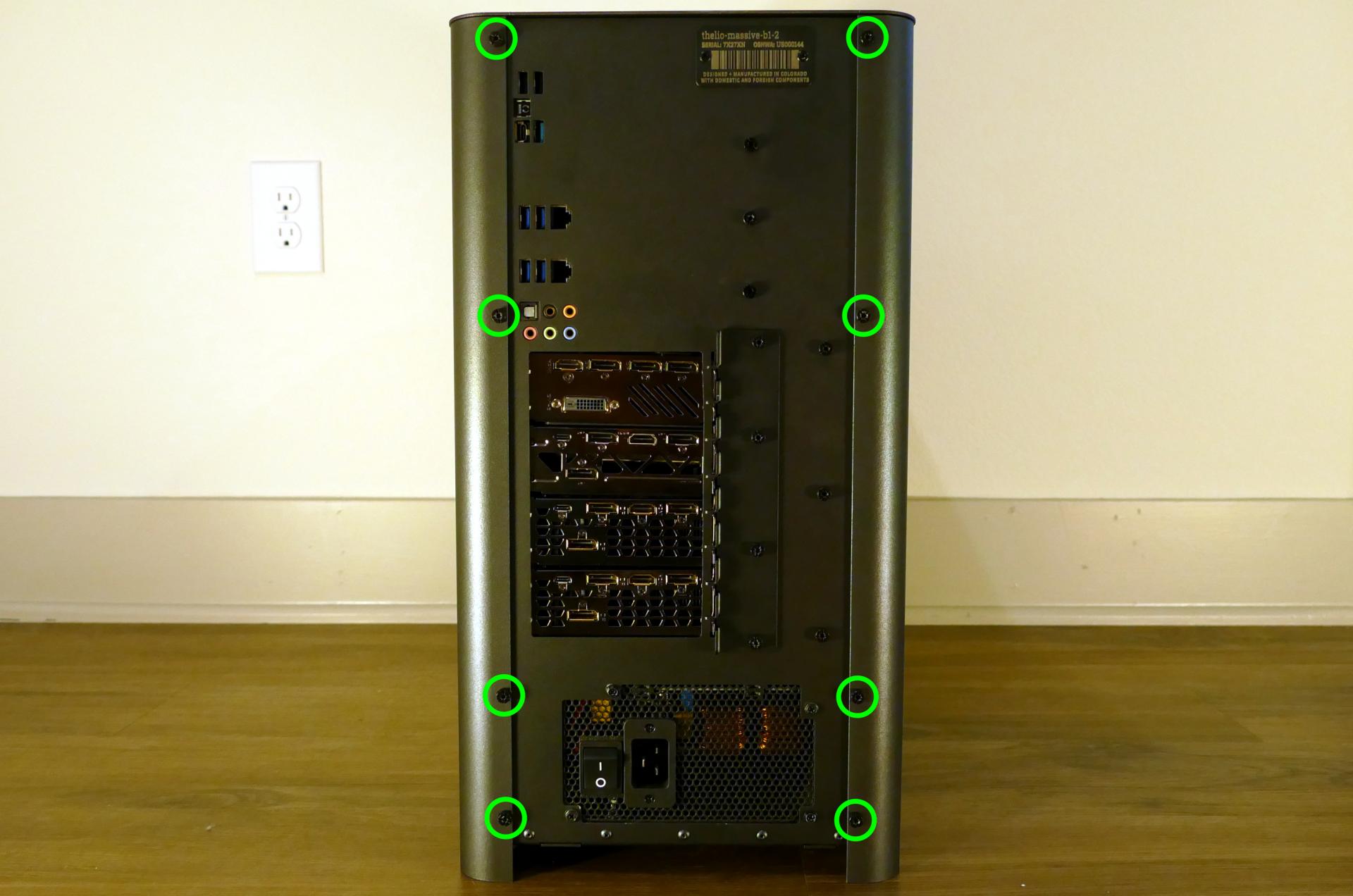
- Slide the top case up and off of the machine.
Removing the inner partition:
The inner partition provides a brace for the outer case and helps hold the internal components in place. The partition needs to be removed to access most internal components.
Tools required: Cross-head (Phillips) screwdriver (optional)
Time estimate: 5 minutes
Difficulty: Easy ●
Steps to remove the inner partition:
- Follow the steps above to remove the top case.
- Unscrew the three additional back screws holding the inner partition in place from the back.
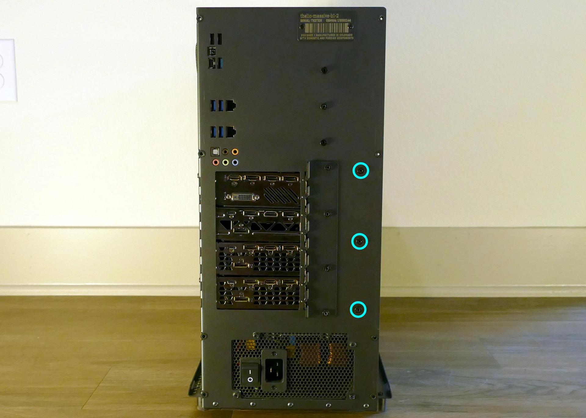
- Unscrew the three inner screws holding the partition in place from the side.
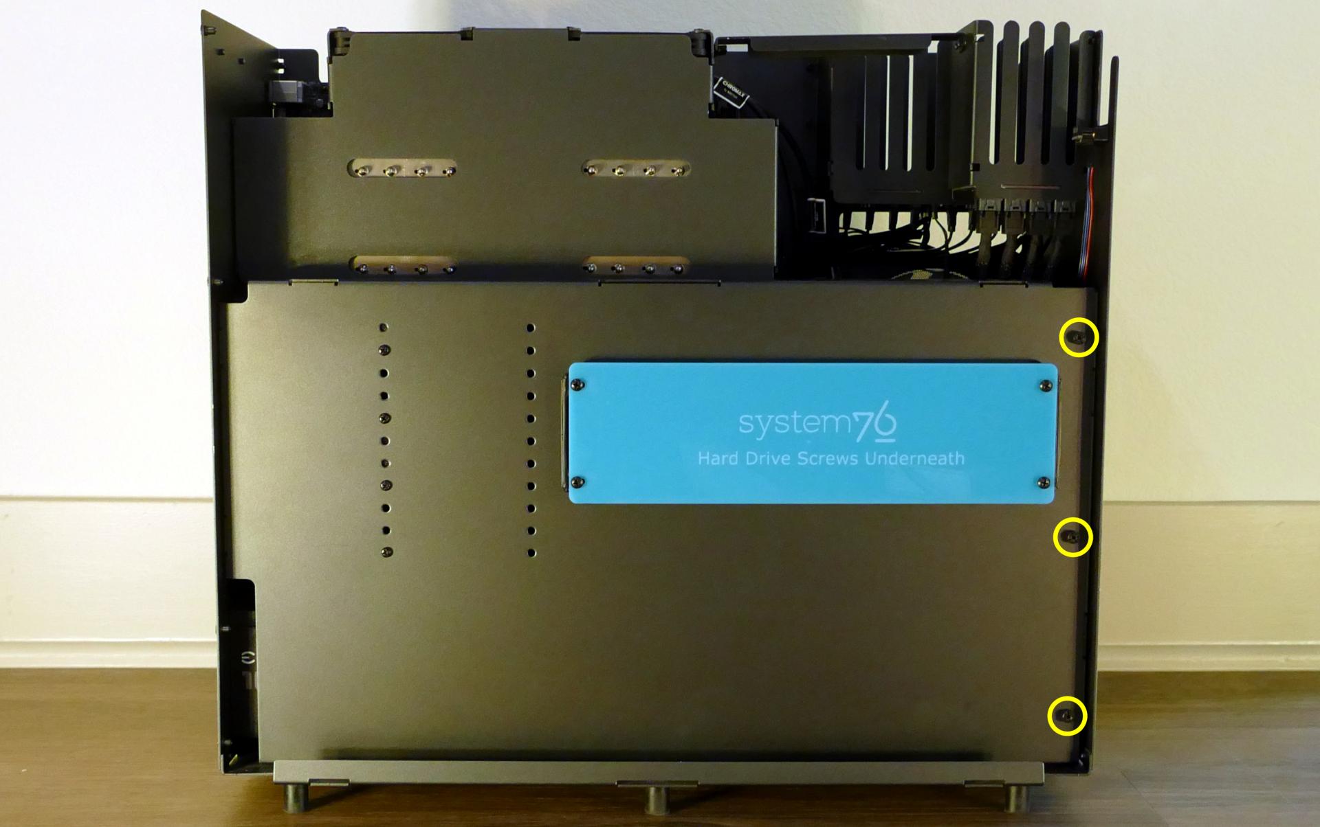
- Lift the inner partition away from the case.
Adding/removing 2.5" storage drives:
Thelio Massive b1.2 supports up to eight 2.5" SATA III drives and up to four 2.5" U.2 NVMe drives (with SAS connectors.)
Tools required: Cross-head (Phillips) screwdriver
Time estimate: 5 minutes
Difficulty: Easy ●
Steps to add/remove 2.5" storage drives:
- Follow the steps above to remove the top case and remove the inner partition.
- Unscrew the four screws holding the plastic screw cover onto the inner partition.
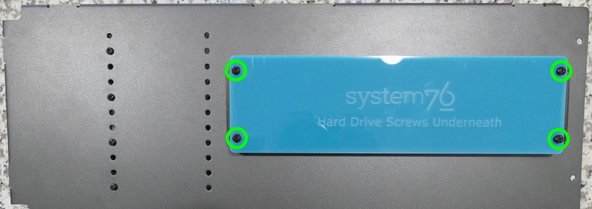
- Pop out one of the black plastic rings and slide four screws (per drive) out of the inner partition.
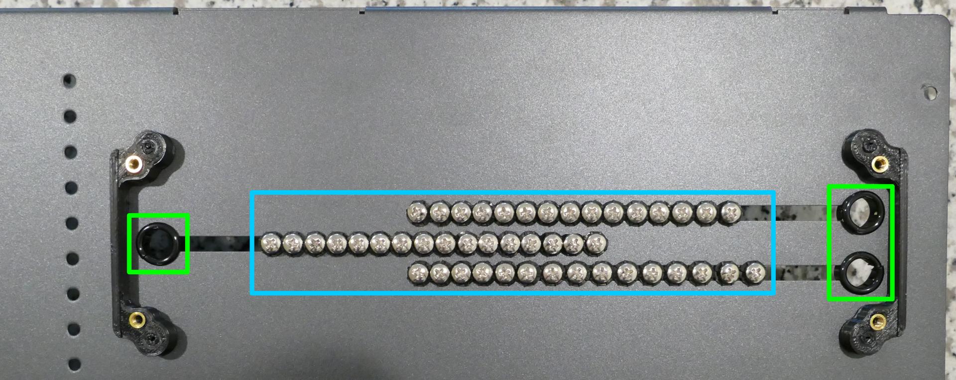
- Insert four screws into each 2.5" storage drive you wish to install.
- Slide each 2.5" drive into one of the slots above the Thelio-IO boards.
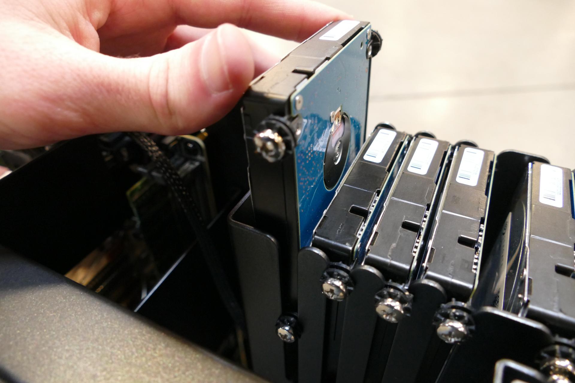
In the below photo, the eight SATA slots are highlighted green, while the four U.2/SAS slots are highlighted blue.
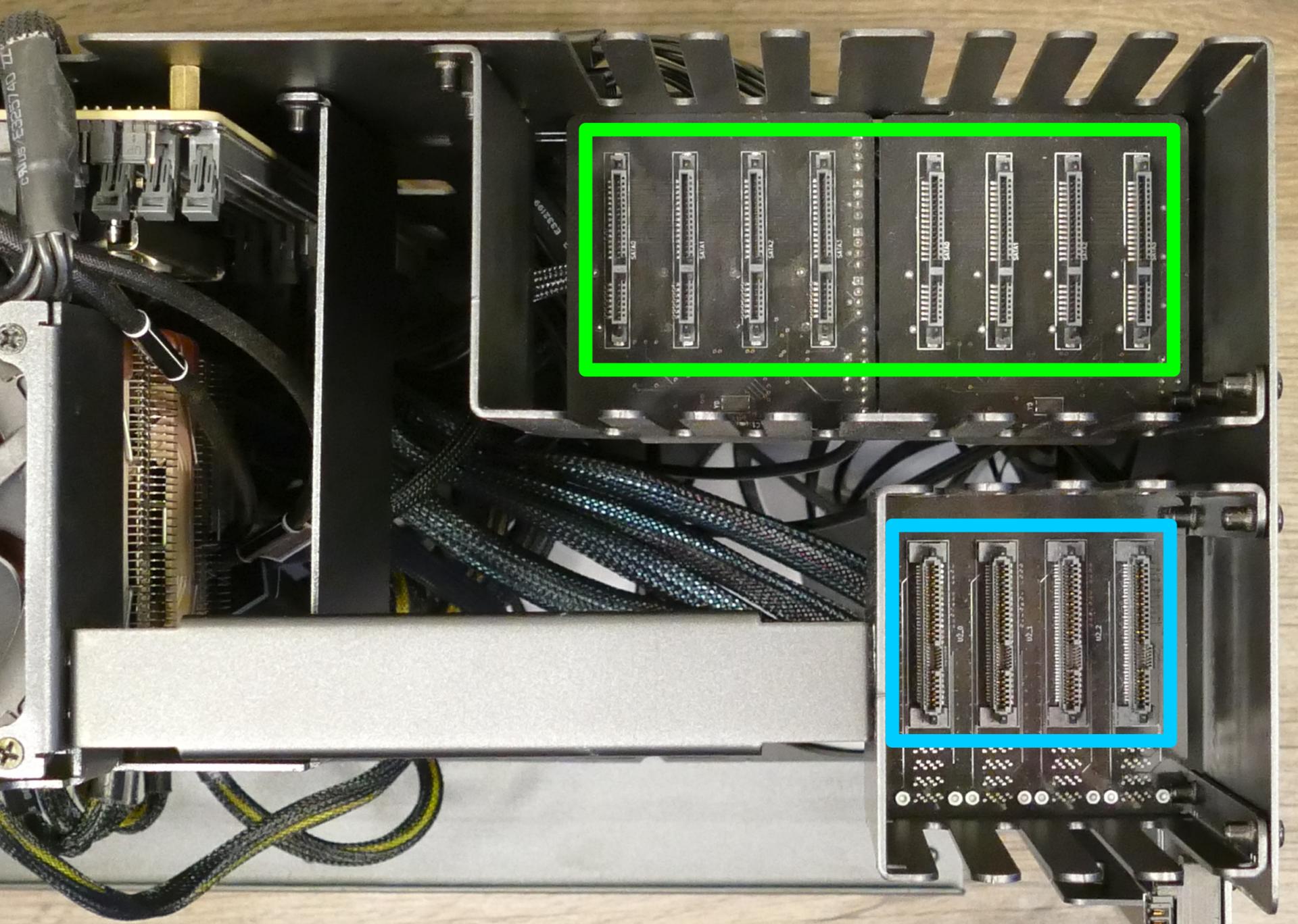
Replacing the case fans:
Thelio Massive b1.2 has four case-mounted fans: two on the bottom, and two on the side next to the motherboard.
Tools required: Cross-head (Phillips) screwdriver
Time estimate: 15 minutes
Difficulty: Medium ●
- Follow the steps above to remove the top case and remove the inner partition.
- Unscrew the fan's screws on the opposite side from where it's mounted. (For the bottom fans, the machine will need to be tilted to access the screws on the bottom.)
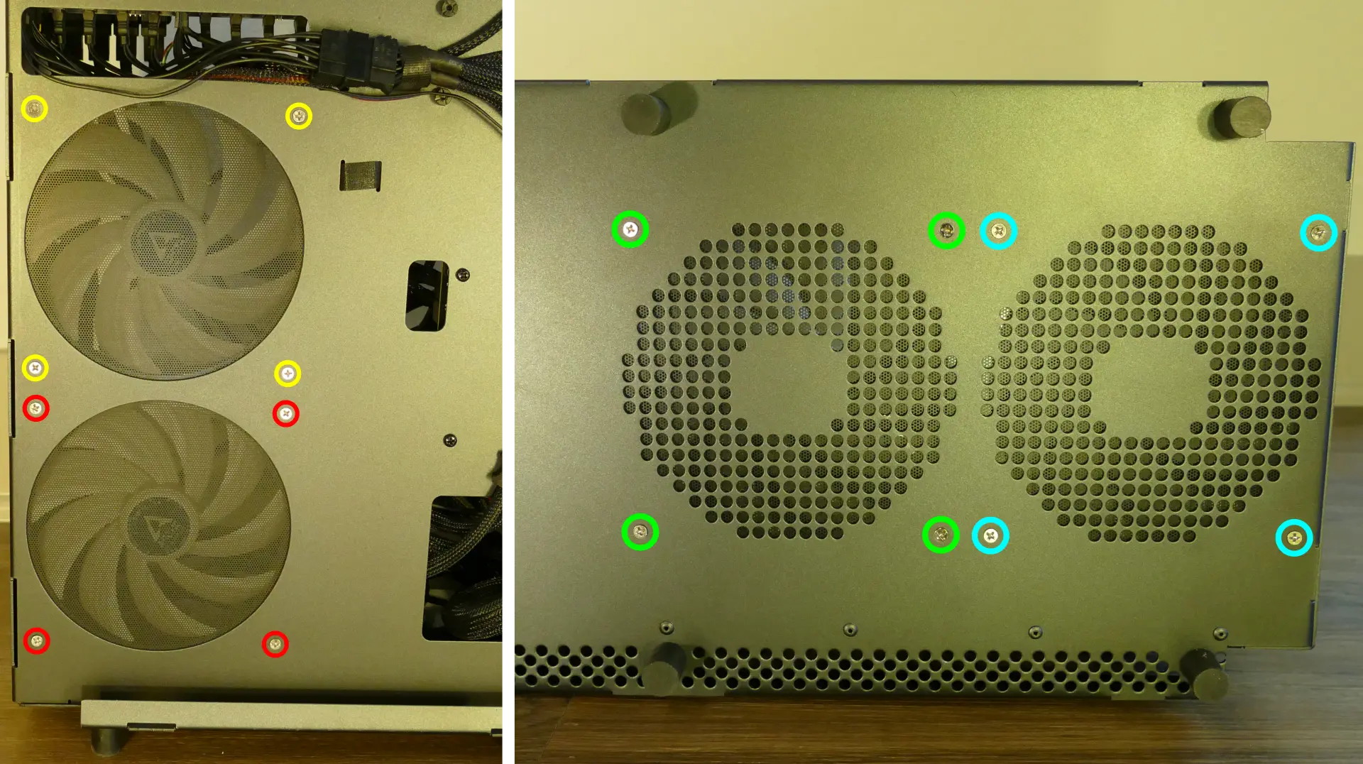
- Unplug and remove the fan.
- When replacing the fan, the components should be mounted in the following order:
- Chassis
- Dust filter
- Acrylic spacer
- Fan
Replacing a GPU:
Thelio Massive supports up to four dual-slot GPUs with PCIe 3.0 x16. Mixing NVIDIA and AMD GPUs is not recommended.
Tools required: Cross-head (Phillips) screwdriver
Time estimate: 10 minutes
Difficulty: Easy ●
Steps to replace a GPU:
- Follow the steps above to remove the top case and remove the inner partition.
- Unscrew the four back screws holding the PCIe bracket in place, then remove the PCIe bracket.
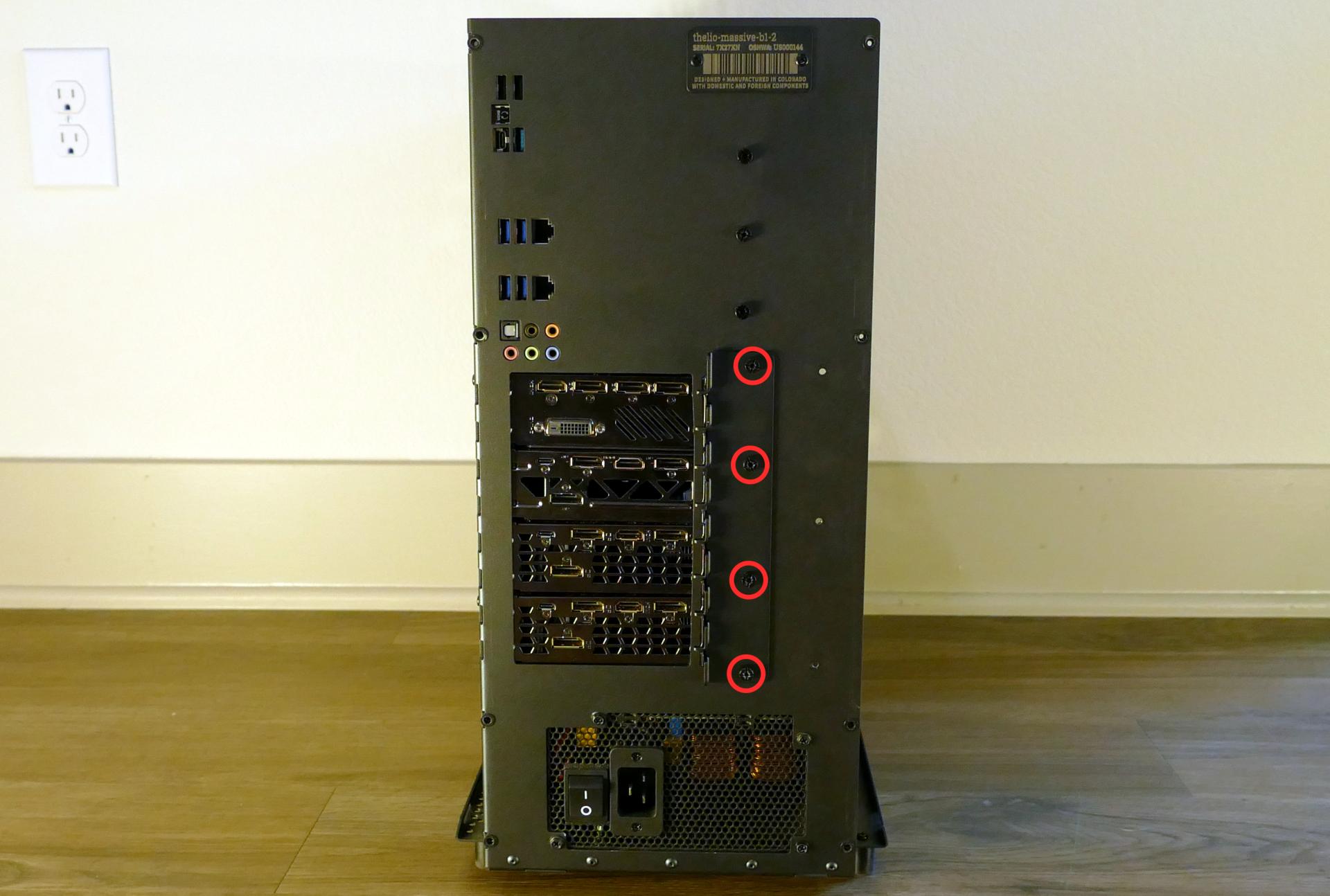
- If you're removing a GPU, unplug the GPU power cable from the right side of the card. Hold down the latch on the connector while unplugging the cable.
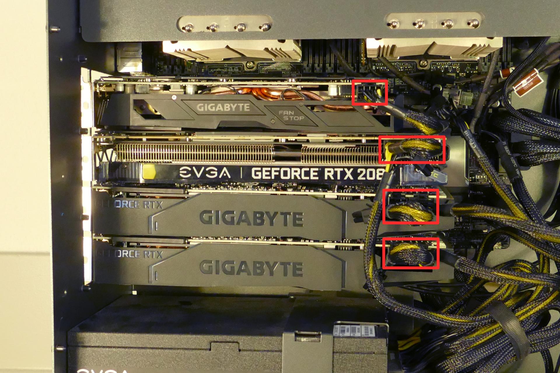
- Hold the latch on the motherboard to free the PCIe connection, then pull the card out of the slot.
- If removing one of the inner GPUs, it may be necessary to remove one of the outer GPUs first in order to reach the latch.
- If space is tight, a long object such as a screwdriver can be used to press the latch.
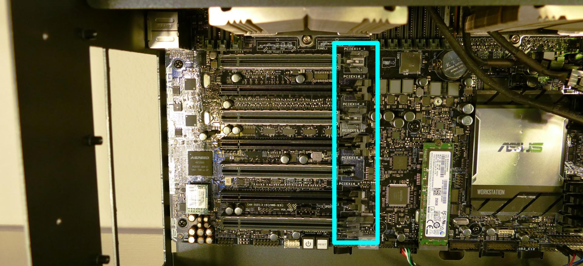
- When installing new GPUs, the slots should be utilized in the following order:
- Primary GPU: third slot from the top.
- Secondary GPU: fifth slot from the top.
- Tertiary GPU: seventh slot from the top (bottom slot).
- Quaternary GPU: top slot.
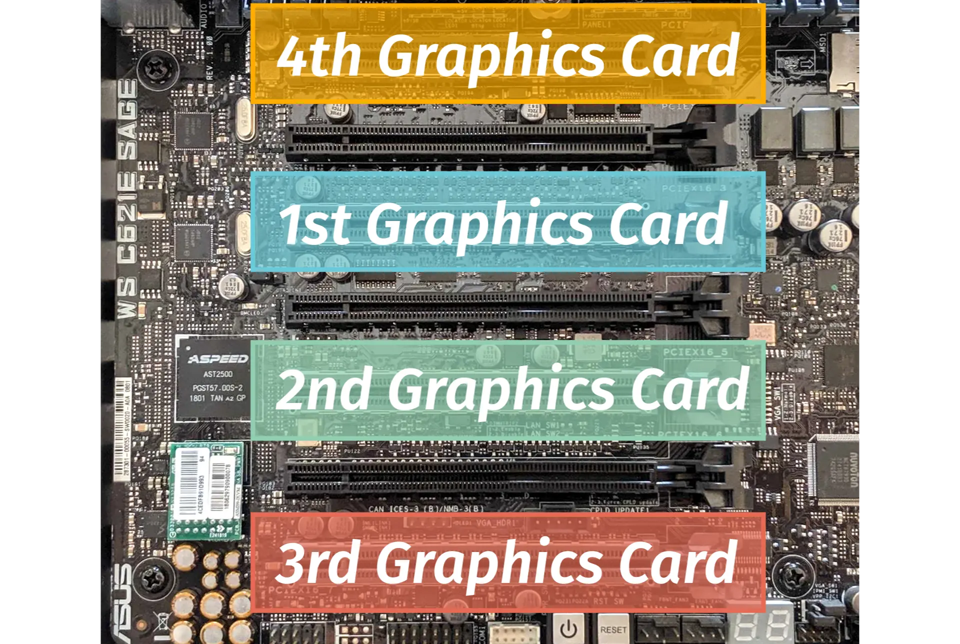
- After inserting the new GPU into its slot, connect the power cables. The maximum number of power cables are preinstalled in your system, but some may be tied back using velcro if the system shipped with less than four GPUs.
- Once all GPUs are installed, replace the back PCIe bracket, inner partition, and top case.
- The inner partition includes a plastic GPU brace, which may be sized differently depending on how many GPUs your system shipped with. To remove the brace, unscrew it from the inner partition.
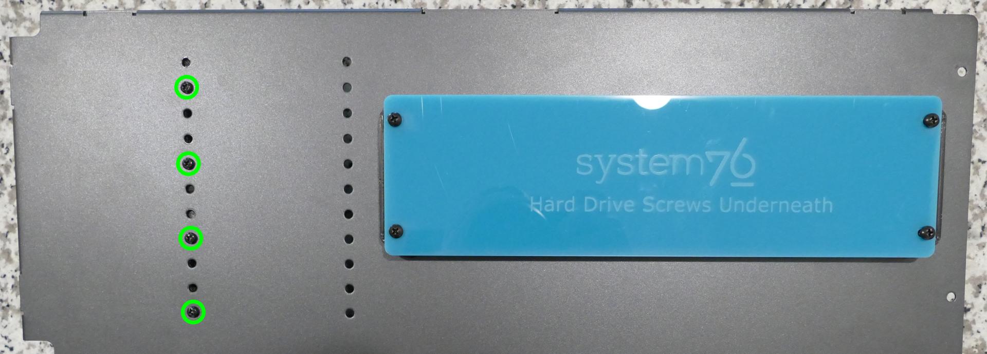
The plastic GPU brace's primary function is to prevent damage during shipping. The system can be run without the brace if it doesn't fit an upgraded card; the back PCIe bracket provides primary support for the GPUs.
Replacing the M.2 drive:
Thelio Massive has one M.2 slot, which supports either PCIe NVMe Gen 3 x4 or SATA III. The following M.2 sizes are supported: 2242, 2260, 2280, 22110.
Tools required: Cross-head (Phillips) screwdriver
Time estimate: 15 minutes
Difficulty: Easy ●
Steps to replace the M.2 drive:
- Follow the steps above to remove the top case, remove the inner partition, and remove the GPUs.
- Unscrew the retainer screw opposite the M.2 slot.
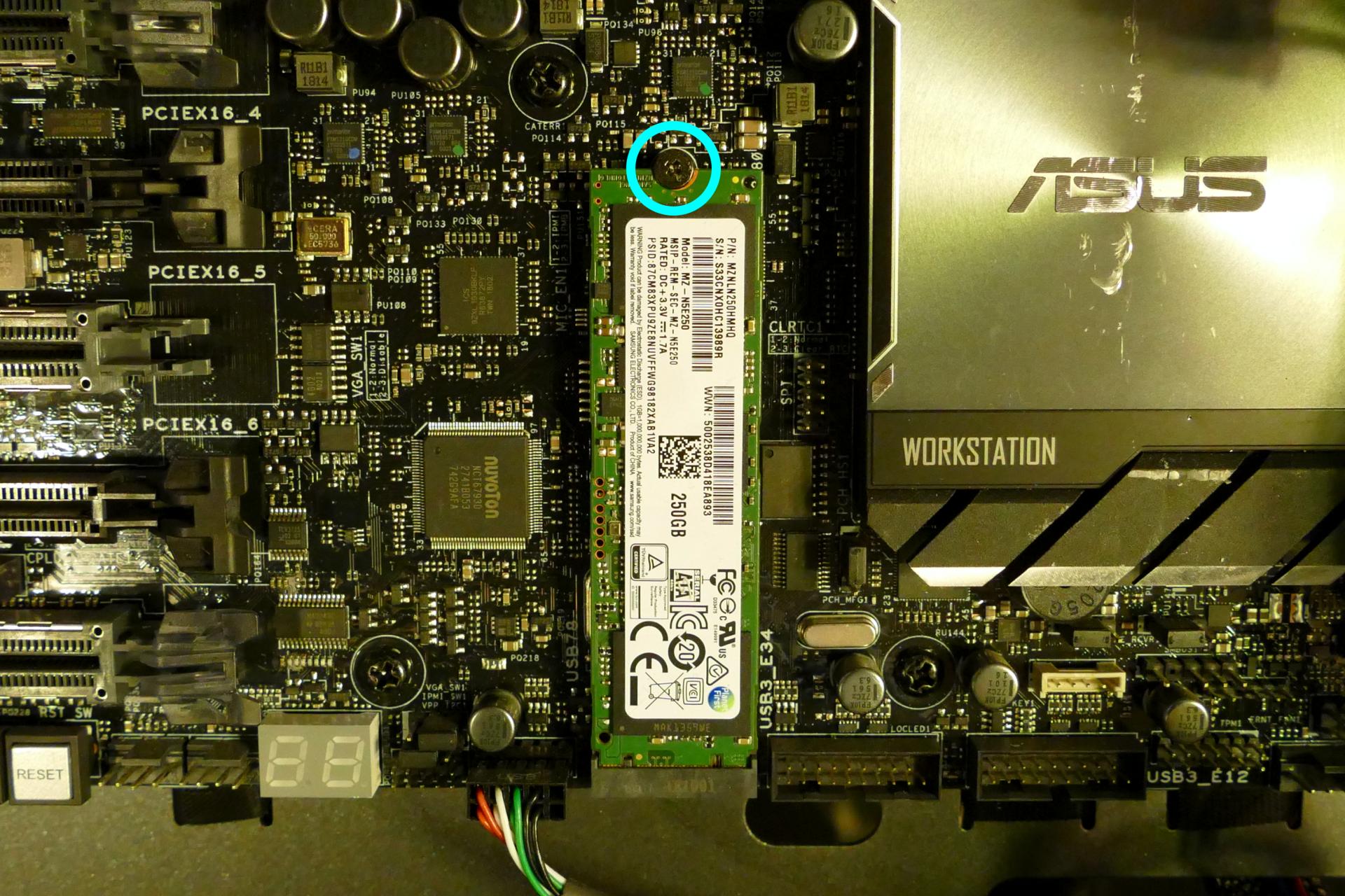
- Remove the existing M.2 drive by pulling it out of the slot.
- Insert the new M.2 drive into the slot and hold it in place.
- Replace the retainer screw.
- Replace the GPUs, inner partition, and top case.
Removing the CPU duct:
The CPU duct guides airflow through the CPU coolers. It covers the CPUs and RAM slots on the motherboard.
Tools required: Cross-head (Phillips) screwdriver (optional)
Time estimate: 7 minutes
Difficulty: Easy ●
Steps to remove the CPU duct:
- Follow the steps above to remove the top case and remove the inner partition.
- Unplug the connectors for the two top exhaust fans. (The top exhaust fans are secured to the CPU duct.)
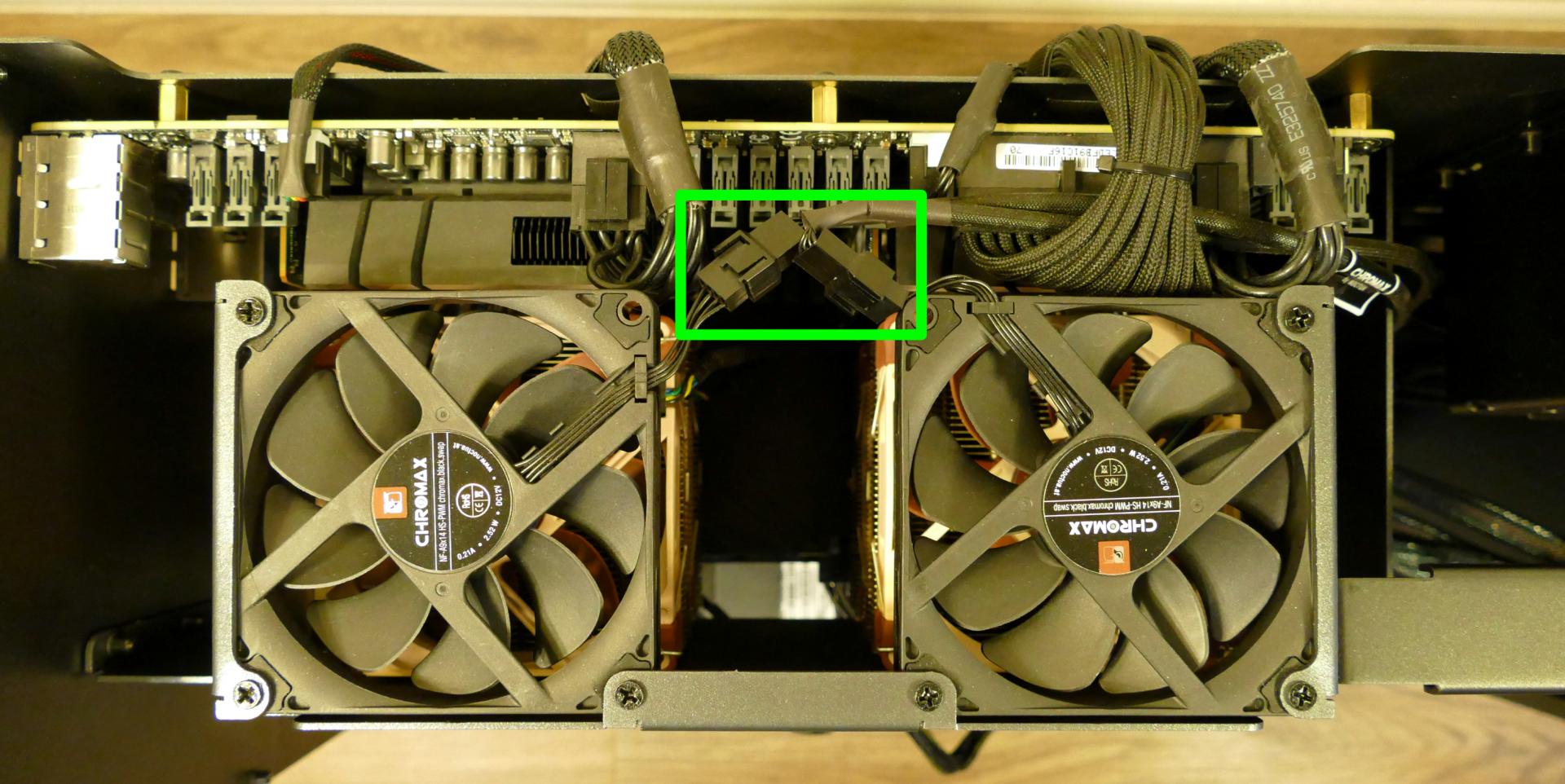
The connectors (highlighted above) attach the top exhaust fans to extension cables, which attach to a five-port hub along with the CPU fans. It is not necessary to remove the extension cables.
- Unscrew the three back screws holding the CPU duct in place.
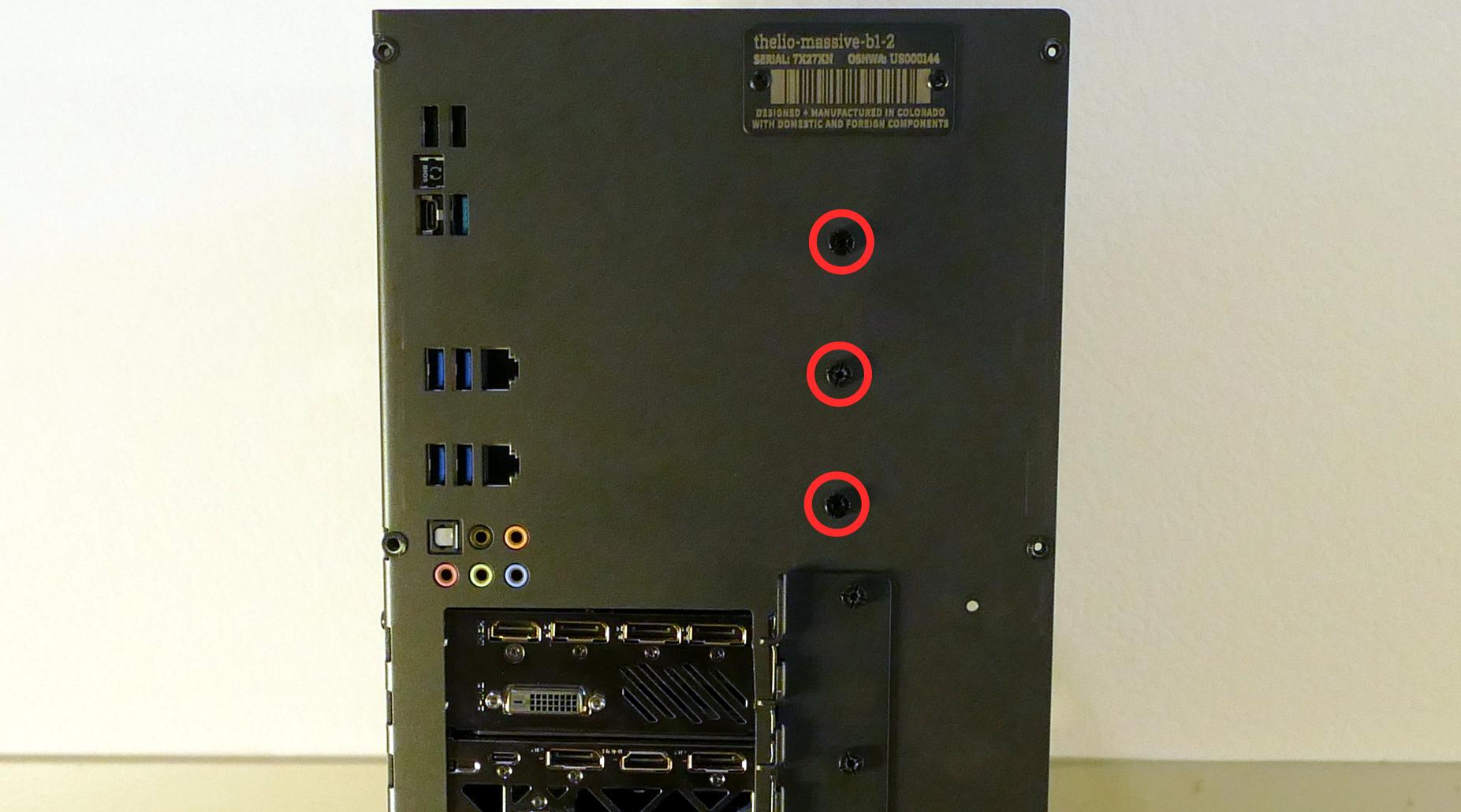
- Unscrew the three side screws holding the CPU duct in place (on the opposite side from the motherboard.)
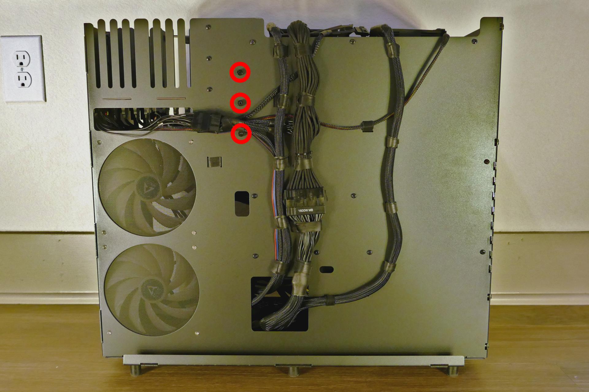
- Pull the CPU duct away from the machine.
Note for older revisions: thelio-massive-b1.0 included two additional screws connecting the top crossbar to the CPU duct. The top crossbar is not attached to the CPU duct on this revision.

Replacing the RAM:
Thelio Massive b1.2 supports up to 1536GB (12x128GB) of RAM, or 768GB (6x128GB) per CPU. The RAM sticks are Registered ECC DDR4 DIMMs running at a speed of 2933MHz. If you've purchased new RAM, need to replace your RAM, or are reseating your RAM, follow these steps.
Tools required: Cross-head (Phillips) screwdriver (optional)
Time estimate: 15 minutes
Difficulty: Easy ●
Steps to replace the RAM:
- Follow the steps above to remove the top case, remove the inner partition, and remove the CPU duct.
- To remove an existing RAM stick, flip the top latch up away from the stick, then pull the stick out of the slot, starting from the top edge. (The bottom of the RAM slot does not move.)
-
Insert the new RAM (or re-seat the existing RAM) into the slot. The RAM stick will only fit in one direction; the larger group of pins goes on top. Use the following guides for placement of the RAM sticks:
- Single-CPU RAM slot placement:

- Dual-CPU RAM slot placement:

- Single-CPU RAM slot placement:
-
Replace the CPU duct, inner partition, and top case.
Replacing the CPU fans:
Thelio Massive b1.2 contains four CPU fans (two per CPU.) All coolers and fans are preinstalled, regardless of how many CPUs the system shipped with.
Tools required: Cross-head (Phillips) screwdriver (optional)
Time estimate: 15 minutes
Difficulty: Easy ●
Steps to replace the CPU fans:
- Follow the steps above to remove the top case, remove the inner partition, and remove the CPU duct.
- Each fan is secured by two clips (one on each side). Pull the clip down (away from the fan), then sideways (away from the heatsink) to release the fan.
- Once the fan is free, lift it away from the heatsink and unplug the four-pin connector attaching it to the Y-cable.
- Two Y-cables connect two CPU fans each to a five-port hub, which also connects to the extension cables for the top exhaust fans.
- The top exhaust fans plug into ports "FAN1" and "FAN2", while the CPU fans plug into ports "FAN3" and "FAN4". The port labeled "CPU" is left disconnected.
- If necessary, lift the bracket off of the old fan and place it onto the new fan.
- Clip the fan back onto the heatsink and plug it into the Y-cable.
Replacing the CPU cooler:
Thelio Massive b1.2 contains two CPU coolers (one for each CPU.) Each cooler contains two fans. All coolers and fans are preinstalled, regardless of how many CPUs the system shipped with.
Tools required: Hex key (included in Thelio Massive case), cross-head (Phillips) screwdriver (optional)
Time estimate: 20 minutes
Difficulty: High ●
Steps to replace the CPU cooler:
- Follow the steps above to remove the top case, remove the inner partition, remove the CPU duct, and remove the CPU fans for the cooler you are removing.
- Locate the hex key/Allen wrench, which is attached to the case via the velcro cable ties behind the motherboard.
- While holding the cooler in place so it doesn't fall, loosen the cooler's screws in reverse order, starting with the center screws (labeled #2), then the corner screws (labeled #1).
- The corner screws require reaching the hex key through the holes in the heatsink.
The CPU cooler screws are held in place by springs, and will not detatch once they are loosened.
- Once all four screws are loosened, the CPU cooler (including the CPU) will lift away from the motherboard.
- Caution: Be careful not to bend any of the gold pins on the CPU socket, and do not touch the gold pads on the CPU.
- When replacing the CPU cooler, tighten the screws in the order they are labeled, starting with the corner screws (labeled #1), then the center screws (labeled #2).
- See Replacing the CPU/thermal paste for more information about correctly orienting the CPU/cooler.
Replacing the CPU/thermal paste:
The CPUs clip into the heatsinks before the heatsinks are installed onto the motherboard.
Tools required: Hex key (included in Thelio Massive case), cross-head (Phillips) screwdriver (optional)
Time estimate: 25 minutes
Difficulty: High ●
Steps to replace the CPU/thermal paste:
- Follow the steps above to remove the top case, remove the inner partition, remove the CPU duct, remove the CPU fans, and remove the CPU cooler.
- The CPU is held onto the heatsink by two plastic clips. Release one of the clips by pulling down on the large plastic tab, then carefully lift the CPU off of the heatsink.
- Caution: Do not touch the gold pads on the CPU.
- It may take some pressure to break the seal of the thermal paste.
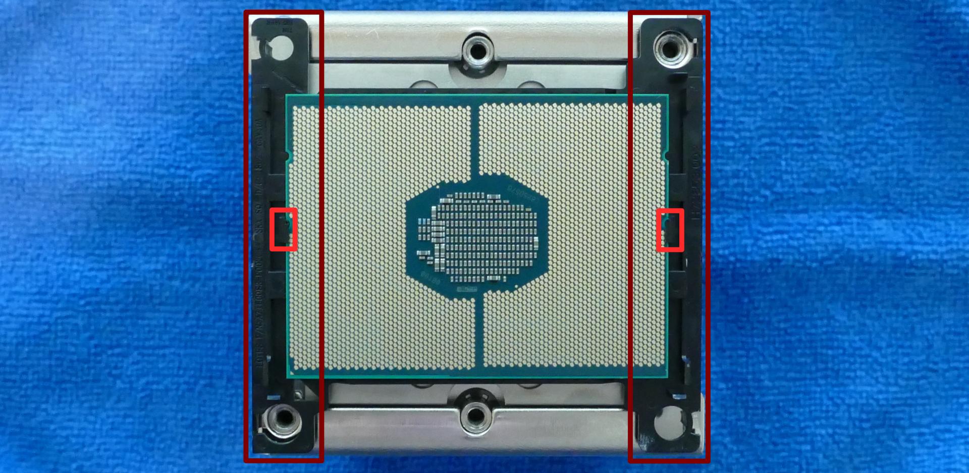
- Remove the black plastic clip from the heatsink by pulling the tabs on each corner.
- Using a paper towel, clean the existing thermal paste off of the heatsink and CPU. You may also use a small amount of rubbing alcohol if the old paste is dried or difficult to remove.
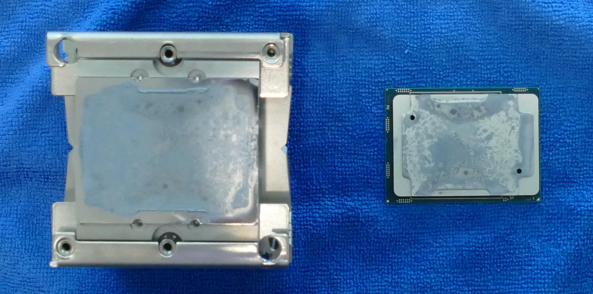
- Place the black plastic clip back onto the heatsink and apply thermal paste to the heatsink.
- Place the CPU back into the black plastic clip. One corner of the CPU and one corner of the clip are marked with triangles; be sure to match these triangles together.
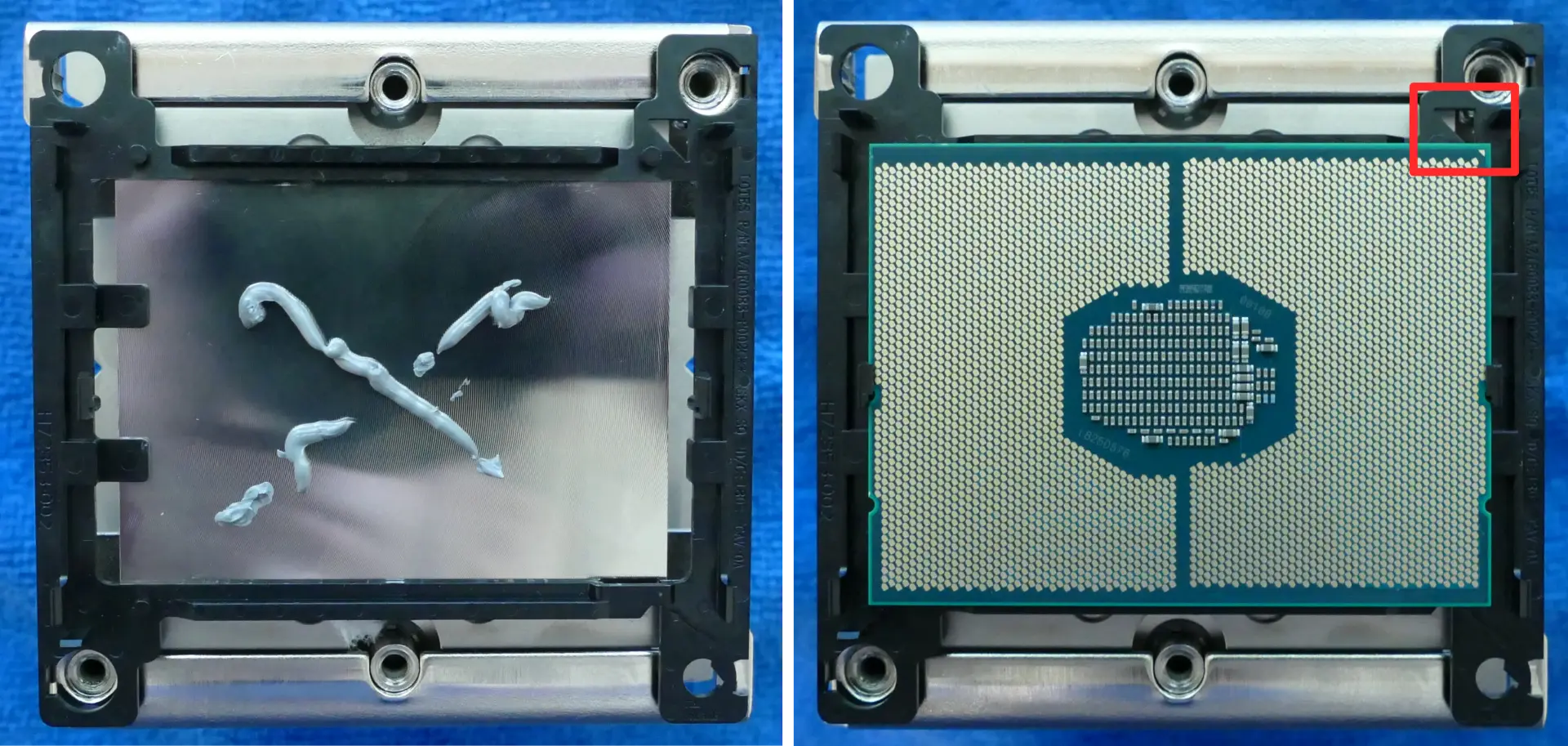
- Place the heatsink/CPU back onto the motherboard, matching the triangles on the plastic clip/CPU (highlighted above) with the diagonal corner on the CPU socket (highlighted below).
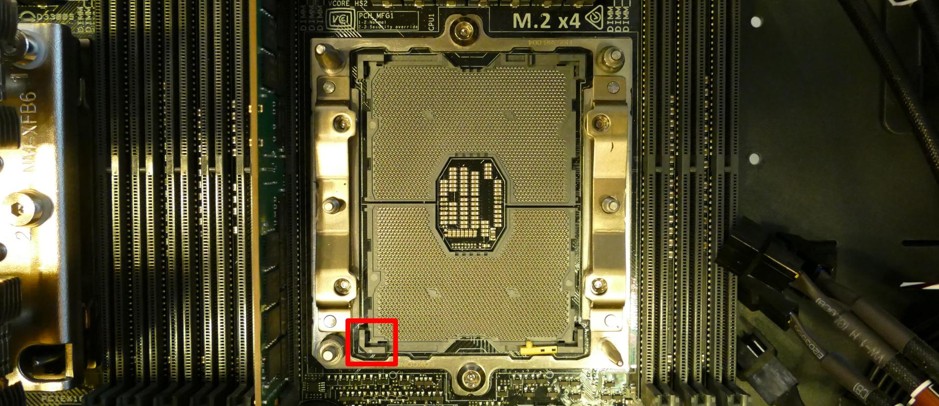
- See Replacing the CPU cooler for more information about re-attaching the cooler to the motherboard.
Replacing the top exhaust fans:
The top exhaust fans assist the CPU fans in expelling hot air from the case.
Tools required: Cross-head (Phillips) screwdriver
Time estimate: 10 minutes
Difficulty: Easy ●
Steps to replace the top exhaust fans:
- Follow the steps above to remove the top case and remove the inner partition. (The CPU duct can optionally be removed.)
- Unscrew the three screws attaching the fan to the CPU duct.
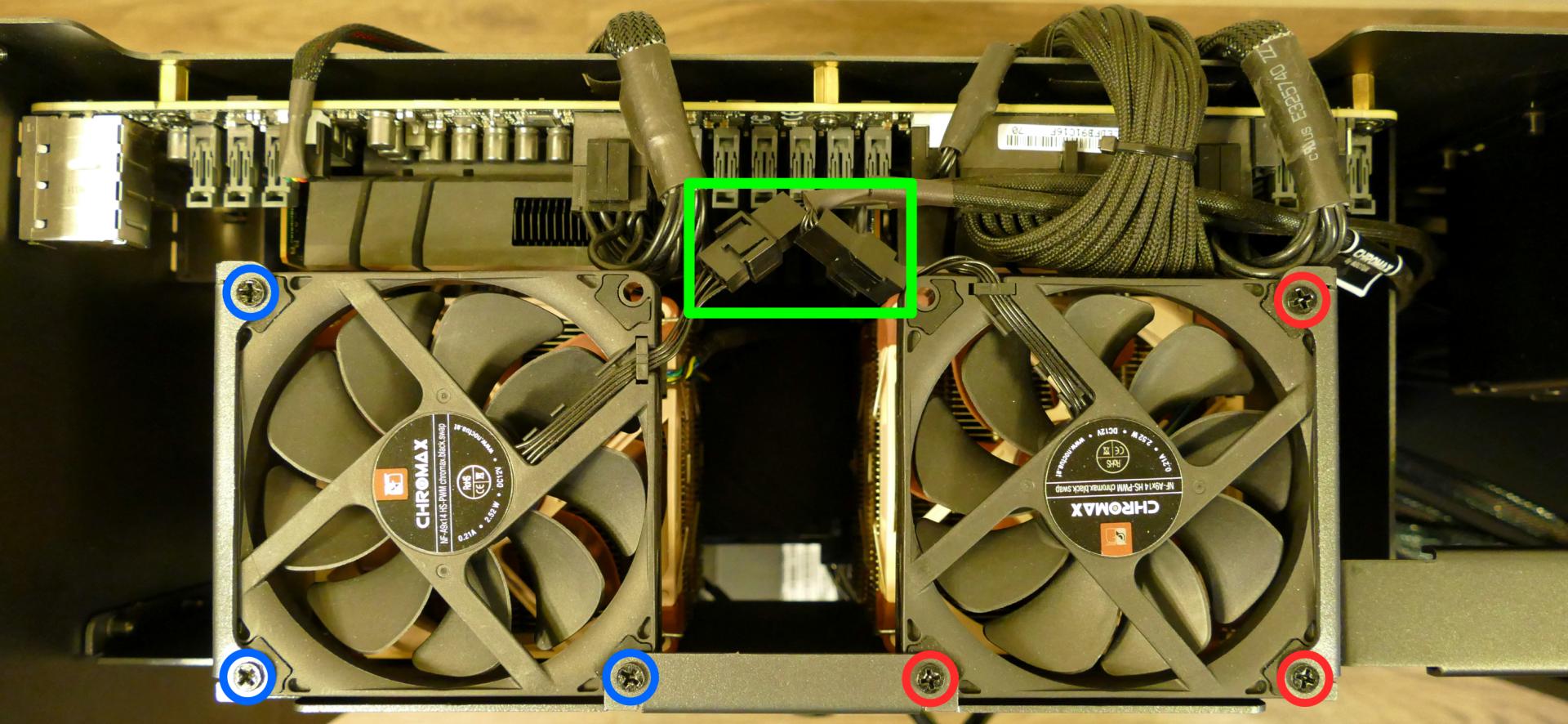
- Unplug the fan from the extension cable and remove it from the case.
- Screw the new fan into the CPU duct, plug it in, and replace the inner partition and top case.
Troubleshooting the power button:
If the front power button doesn't power the machine on or doesn't light up when the system is powered on, try the following troubleshooting steps:
- Ensure the system powers on normally using the internal power button.
- Reseat the front power button to ensure it's making proper contact.
- Check the wiring for the front power button.
- Replace the front power button, if necessary.
Tools required: Cross-head (Phillips) screwdriver (optional)
Time estimate: 20 minutes
Difficulty: Medium ●
Steps to power the machine on using the internal power button:
- Follow the steps above to remove the top case and remove the inner partition.
- Ensure the system is plugged into power, and the power supply switch is in the 1 (On) position.
- Push the small button labeled B0 on the Thelio-IO board closest to the front corner of the case.
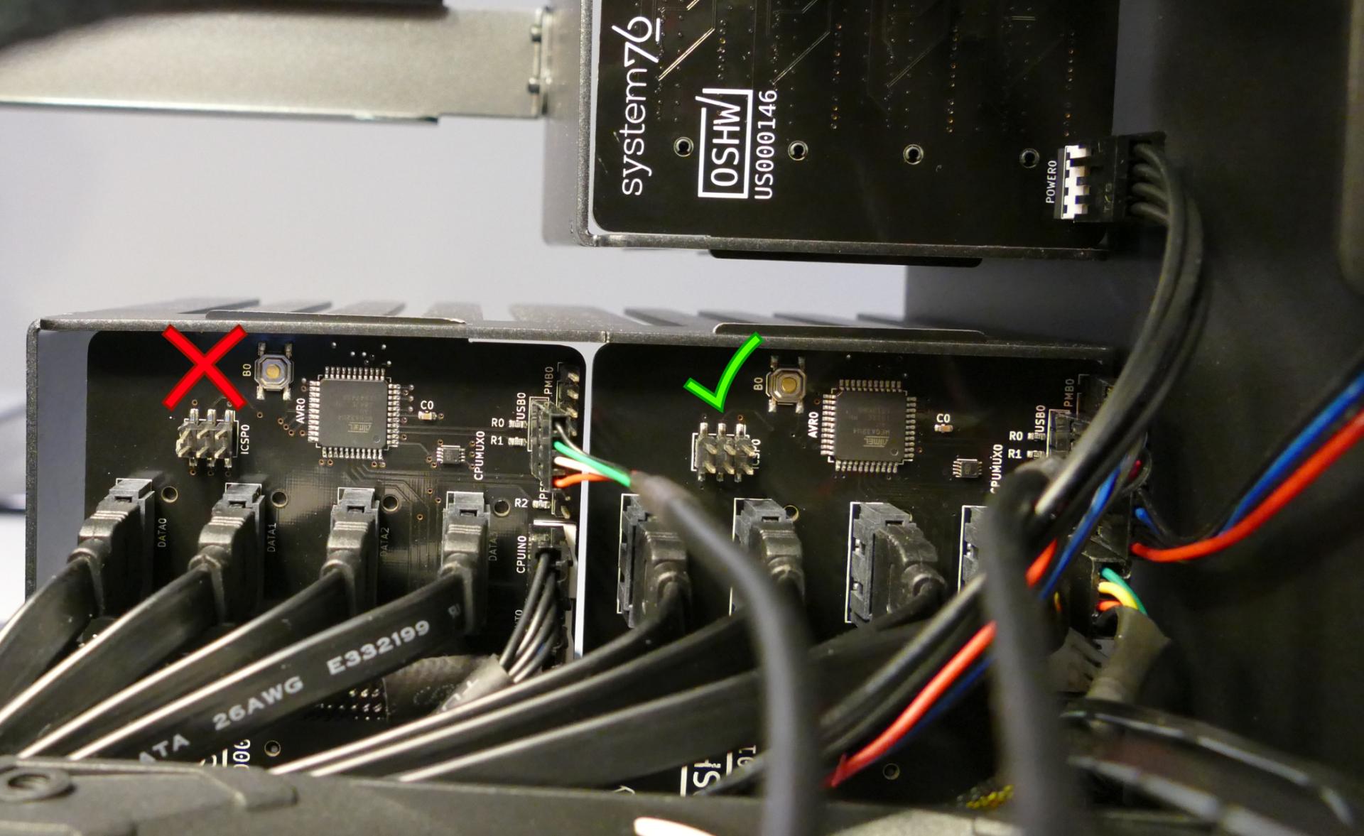
Steps to check the front power button wiring:
- Follow the steps above to remove the top case and remove the inner partition.
- On the back of the power button, the four pins should be connected to the four-wire connector as follows:

- On the front power button receptacle, the four-pin connector should have the red wire on the left and the black wire on the right.
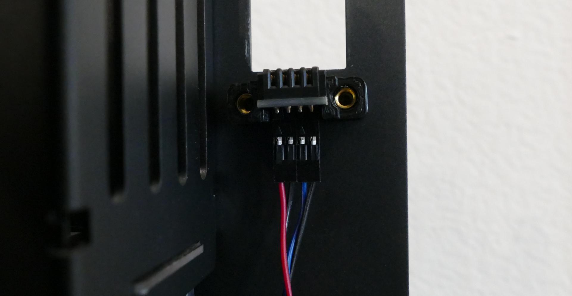
- The front power button receptacle should plug into the
PFPDport on the Thelio-IO board closest to the front corner of the machine, with the red wire on the left and the black wire on the right.
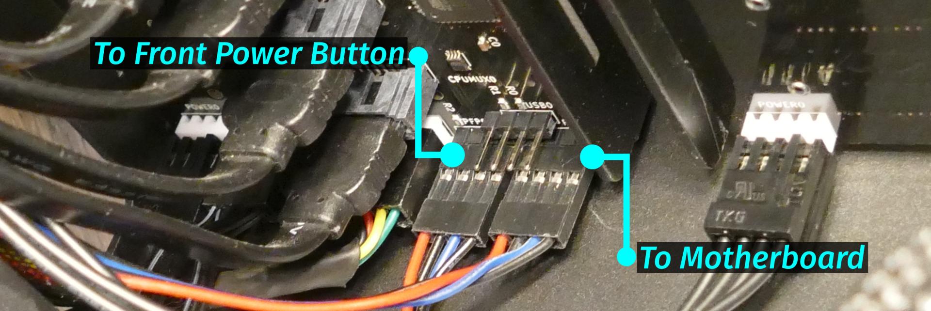
- The
PMBDport on the Thelio-IO board should connect to the motherboard:- The red wire on the four-port connector should be on the left (the farthest in) on the Thelio-IO board.
- The other side of the cable connects to the bottom right of the motherboard:
- The individual black wire plugs into
POWERLED+. - The individual red wire plugs into
POWERLED-. - The two-wire connector plugs into
POWERBTN#andGND, with the blue wire on the left (intoPOWERBTN#.)
- The individual black wire plugs into
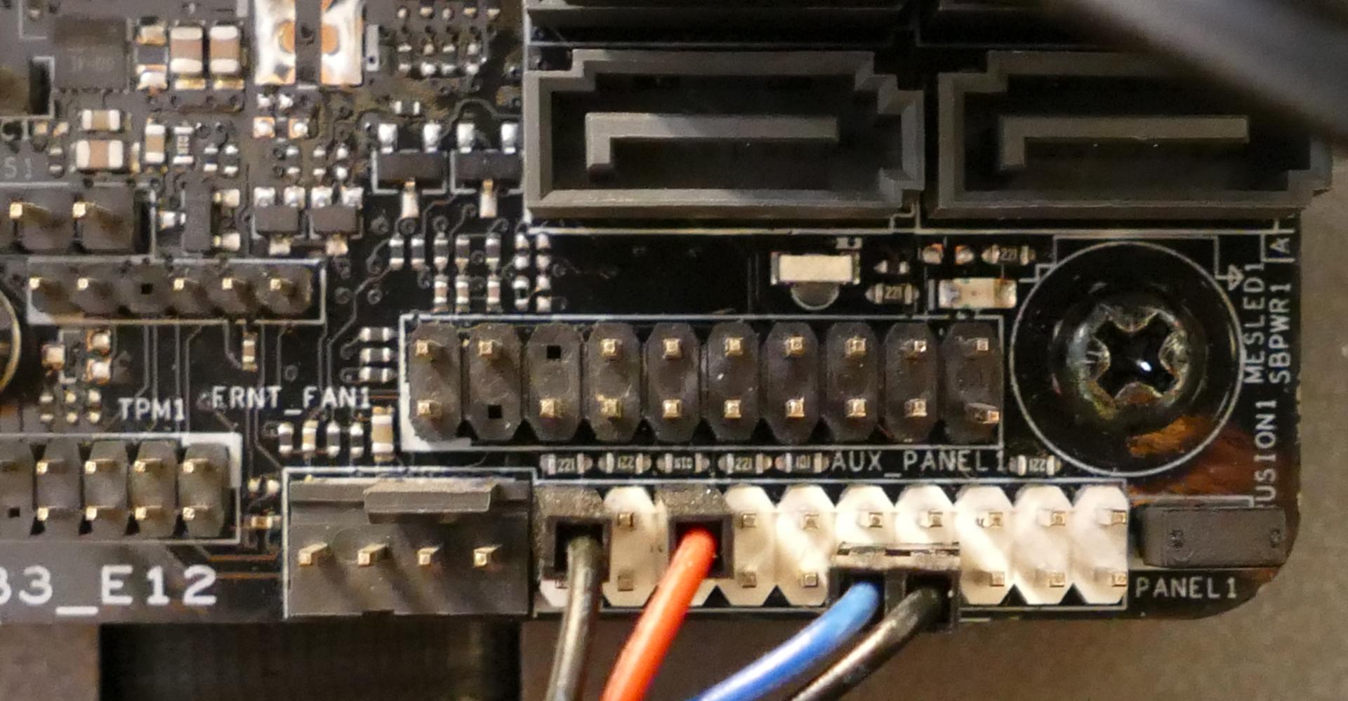
Steps to replace the power button:
- Follow the steps above to remove the top case.
- Follow the instructions in the Replace the Thelio Power Button support article.
Troubleshooting the Thelio-IO USB connection:
The Thelio-IO boards connect to the motherboard's USB headers for firmware updates and fan control within the host OS. If the fans seem to be stuck on full blast, check the Thelio-IO USB connections.
Tools required: Cross-head (Phillips) screwdriver (optional)
Time estimate: 15 minutes
Difficulty: Medium ●
Steps to check the USB wiring:
- Follow the steps above to remove the top case.
- Two of the Thelio-IO boards have
USB0ports. The port on each board connects to a four-pin cable with the red wire on the left (farthest into the case). - The two four-pin cables plug into the motherboard's USB headers just to the left of the M.2 slot.
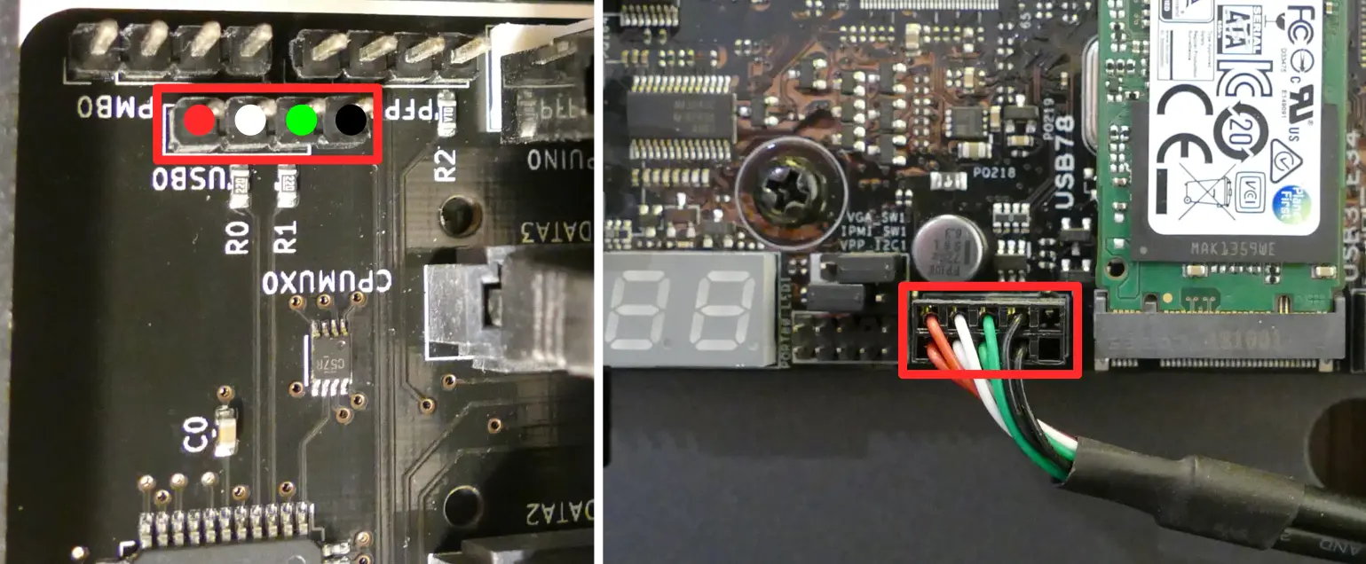
Thelio Mega (thelio-mega-r4-n3)
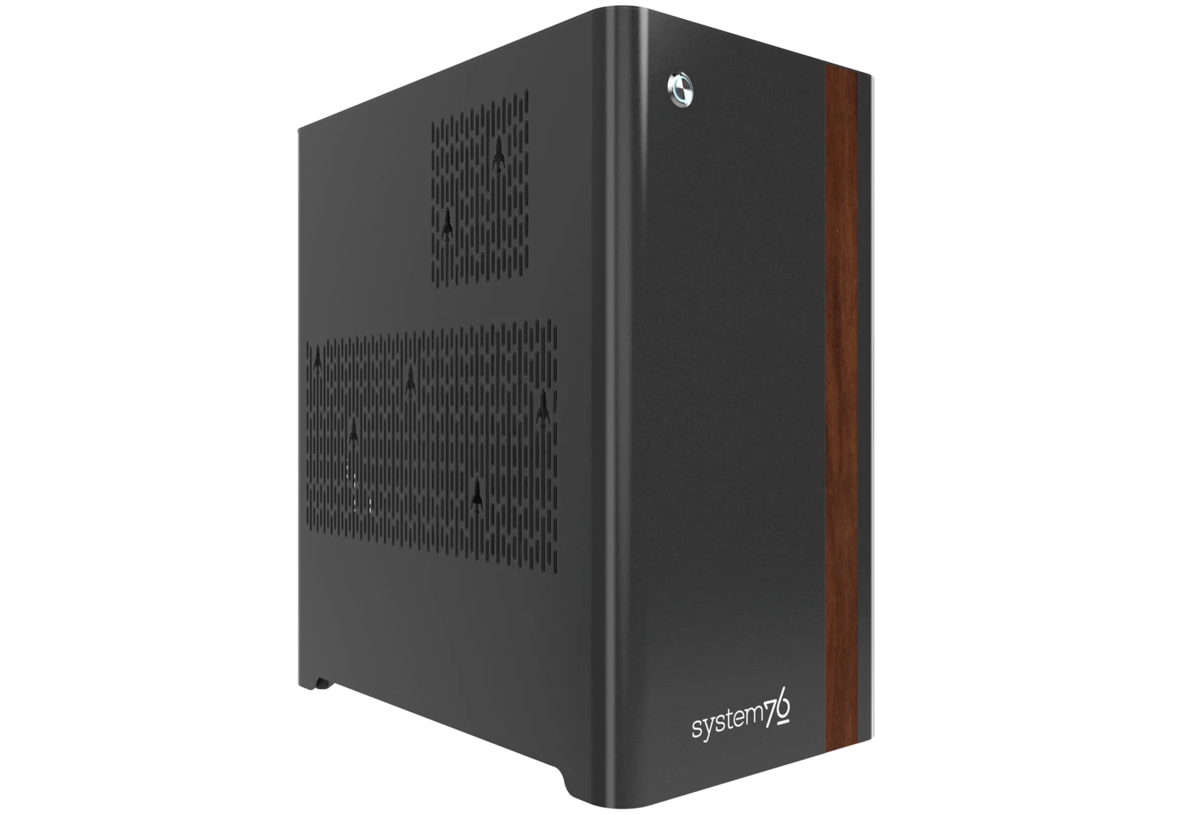
The System76 Thelio Mega is a desktop with the following specifications:
- CPU options
- Motherboard
- Gigabyte TRX50 AI TOP running System76 Firmware (non-open)
- AMD TRX50 chipset
- Daughterboard
- Thelio Io board running open-source firmware
- Revision 2.3
- Thelio Io board running open-source firmware
- GPU options
- Up to four GPUs (4x PCIe 5.0 x16)
- Ships with up to three GPUs
- Fourth GPU subject to space & power constraints
- GPU size:
- Internal clearance: 369.10mm
- Recommended maximum length: 359.10mm
- Tested with the following GPUs:
- NVIDIA RTX Pro 6000
- 4x DisplayPort 2.1b
- NVIDIA A800
- Compute only (no video ports)
- Ships with NVIDIA A400 for display
- 4x Mini DisplayPort 1.4a
- NVIDIA RTX 6000 ADA
- 4x DisplayPort 1.4
- Supports Quadro Sync II in multi-GPU configurations
- NVIDIA RTX 5000 ADA
- 4x DisplayPort 1.4a
- NVIDIA RTX 4500 ADA
- 4x DisplayPort 1.4a
- NVIDIA RTX 4000 ADA
- 4x DisplayPort 1.4a
- NVIDIA GeForce RTX 5090
- 3x DisplayPort 2.1b
- 1x HDMI 2.1b
- NVIDIA GeForce RTX 5080
- 3x DisplayPort 2.1b
- 1x HDMI 2.1b
- NVIDIA A400
- 4x Mini DisplayPort 1.4a
- NVIDIA RTX Pro 6000
- Up to four GPUs (4x PCIe 5.0 x16)
- Memory
- Up to 512GB (8x64GB) quad-channel ECC Unbuffered DDR5 DIMMs @ 5600 MHz
- Tested with the following RAM modules (may ship with other tested modules):
- Micron MTC40F2046S1RC56BR (64GB/stick)
- Kingston KF556R28RBE2K4 (32GB/stick)
- Networking
- 2x 10-Gigabit Ethernet (Marvell AQtion AQC113C 10GbE LAN chip)
- Wireless (depending on ship date):
- After November 2025: Wi-Fi 7 + Bluetooth 5.3 (Qualcomm QCNCM865)
- Before November 2025: Wi-Fi 6E + Bluetooth 5.3 (Intel AX210)
- Power
- C19 power cord
- 1650W PSU
- 80+ Gold Efficiency
- Tested with the following PSU models (may ship with other tested models):
- Sound
- Top:
- Realtek ALC897 chipset
- 3.5mm mic in
- 3.5mm line out
- Realtek ALC897 chipset
- Back:
- Realtek ALC4080 chipset
- 3.5mm mic in
- 3.5mm line out
- HDMI and/or DisplayPort audio out (depending on GPU)
- Realtek ALC4080 chipset
- Top:
- Storage
- 4x M.2 (PCIe Gen 5) SSDs
- 4x 2.5" SATA III
- USB
- Top:
- 1x USB 3.2 Gen 1 (Type-C)
- 1x USB 3.2 Gen 1 (Type-A)
- Back:
- 2x USB4 (Type-C)
- 6x USB 3.2 Gen 2 (Type-A)
- Top:
- Dimensions
- 47.8cm x 26.3cm x 43.8cm
Thelio Mega (External Overview)
Back overview:

Firmware Flash Button:
- The firmware flash button (labeled
Q-Flash Plus) is not needed when performing UEFI firmware updates via the System76 Firmware Manager. Use of this button is not recommended.
Wireless Antenna:
- Thelio Mega R4-N3 ships with an external Gigabyte wireless antenna module. This module should be plugged into the wireless antenna port (labeled
Wifion the machine) before WiFi or Bluetooth are used. - The module can connect in either direction (there's no pin that must be on the left or right).
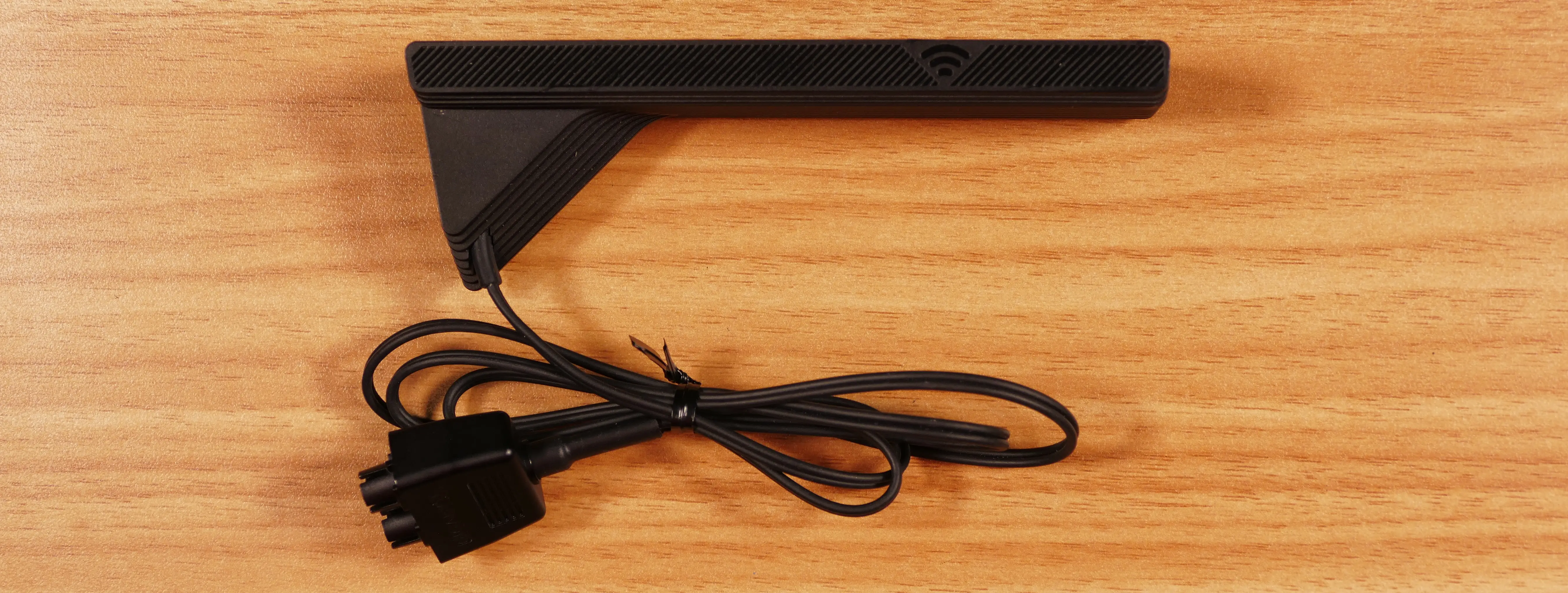
DisplayPort Pass-Through:
- The DisplayPort pass-through input (labeled
DP INon the machine) provides an input to pass a DisplayPort signal from a graphics card into the top USB4 (Type-C) port.- Connect a GPU's DisplayPort output to the DisplayPort pass-through input (
DP IN) port. - Then, connect a USB-C display (or docking station) to the top USB4 (Type-C) port to view the DisplayPort signal.
- The top USB4 (Type-C) port is additionally labeled
DPon the machine to signify that it's the pass-through output port.
- The top USB4 (Type-C) port is additionally labeled
- Connect a GPU's DisplayPort output to the DisplayPort pass-through input (
Power Supply Switch Guide:
Power Switch:
- 1: On
- 0: Off
Fan Curve Switch:
- The PSU fan curve switch (labeled
Smart Zero Fan) should be set toONfor the best fan curve.
Front/side overview:

Top/bottom overview:

Thelio Mega (Internal Overview)
Left side overview:
Chassis components:

- CPU duct is highlighted in red
- Power button receptacle cutout is highlighted in cyan
- Side fan mount is highlighted in green
- PSU bracket is highlighted in yellow
Electronic components:

- CPU heatsink is highlighted in yellow
- RAM slots are highlighted in green
- RAM slots are partially obstructed by the CPU heatsink
- PCIe 5.0 x16 slots are highlighted in red
- Primary GPU slot is the top slot
- M.2 slots are highlighted in cyan
- 2.5" SATA slots are highlighted in pink
- Thelio Io daughterboard is highlighted in white
- Motherboard power button is highlighted in purple
- CMOS battery is highlighted in black
- Power supply is highlighted in orange
Right side overview:

- Back of Thelio Io board is highlighted in cyan
- Internal power button is on the Thelio Io board
- SATA backplane access cutout is highlighted in green
- Power supply access cutout is highlighted in red
Front side overview:

- Power button receptacle cutout is highlighted in cyan
- Thelio Io connector access cutout is highlighted in green
Top overview:

- CPU power connectors are highlighted in red
- Connect to power supply
- Top RAM slot is highlighted in green
- CPU fan input header is highlighted in orange
- Connects to Thelio Io board
- CPU fan output splitters are highlighted in pink
- Connect to the CPU fans and the Thelio Io board
- Top I/O board is highlighted in white
- Connects to motherboard
- 2.5" drive screws are highlighted in yellow
- Power button receptacle is highlighted in cyan
- Connects to Thelio Io board
See the repairs page for detailed information about installing or replacing components.
Thelio Mega (Parts & Repairs)
Many components in your Thelio Mega can be upgraded or replaced as necessary. This page uses photos of the the R4-N3 revision, which indicates:
- R4: The fourth AMD motherboard used in Thelio Mega.
- N3: Based on the third major revision of the Thelio Mega chassis.
- The Thelio Mega form factor is not currently available as a standalone Nebula chassis.
Minor case details may vary based on the production date of the unit, but screw counts, general component locations, and other details should remain the same unless otherwise noted.
Power the machine off, switch off the power supply, and unplug all peripherals before working with any internal components. Then, follow these step-by-step guides for instructions:
- Replacing the front accent strip
- Removing the top case
- Removing the side fan mount
- Replacing the side intake fans
- Adding/removing 2.5" storage drives
- Removing the GPU brace
- Removing the CPU duct
- Replacing a GPU
- Replacing the M.2 drives
- Replacing the CMOS battery
- Replacing the CPU fans
- Replacing the CPU cooler/thermal paste and CPU
- Replacing the RAM
- Opening the PSU chamber
- Replacing the bottom intake fan
- Replacing the power supply
- Removing the top crossbar
- Replacing the Thelio Io board
- Replacing the SATA backplanes
- Replacing the top I/O
- Troubleshooting the power button
Replacing the front accent strip:
Thelio Mega includes a customizable accent panel on the front of the case, which can be swapped to change the case's look and feel. The instructions for swapping the accent are also available in video form.
Tools required: None
Time estimate: 30 seconds
Difficulty: Easy ●
Steps to replace the front accent strip:
- Place the Thelio on the edge of the desk so the front side is hanging off of the desk.
- The Thelio can alternatively be lifted or tilted so the front of the computer is hovering above the desk.
- Slide the accent strip down to unlock it.
- The accent can be gripped at the bottom edge.
- Pull the accent strip off of the case, starting with the bottom edge.
- Place the new accent strip onto the front of the case and slide it up to lock it into place.

Removing the top case:
The top case can be removed to access the internal components.
Tools required: Cross-head (Phillips) screwdriver (optional)
Time estimate: 2 minutes
Difficulty: Easy ●
Steps to remove the top case:
- Remove the eight outer screws holding the top case onto the machine.

- Slide the top case up and off of the machine.
Removing the side fan mount:
The side fan mount holds the two 140mm side intake fans, which cool the GPU(s) and 2.5" storage drives.
Tools required: Cross-head (Phillips) screwdriver
Time estimate: 5 minutes
Difficulty: Easy ●
Steps to remove the side fan mount:
- Follow the steps above to remove the top case.
- Unplug the side fan connector from the top of the side fan mount, next to the back of the chassis.

- Unscrew the four screws holding the side fan mount in place (two on the front of the case, two on the back).
- Pull the side fan mount out of the chassis.
Replacing the side intake fans:
The 140mm side intake fans can be independently replaced.
Part numbers:
- Each side fan is a 140mm Be Quiet! Silent Wings 4 (model number
BQ SIW4-14025-MF-PWM).
Tools required: Cross-head (Phillips) screwdriver
Time estimate: 10 minutes
Difficulty: Easy ●
Steps to replace the side intake fans:
- Follow the steps above to remove the top case and remove the side fan mount.
- Unscrew the four screws holding the fan in place.

- Free the fan cable from the velcro straps and unplug it from the splitter board.
- When installing the new fan, orient the spinning side out of the chassis and the stationary side into the chassis.
- The fan's cable should point towards the same long edge as the splitter board, but the opposite short edge.
Adding/removing 2.5" storage drives:
Thelio Mega R4-N3 supports up to four 2.5" SATA III drives.
Tools required: Cross-head (Phillips) screwdriver
Time estimate: 8 minutes
Difficulty: Easy ●
Steps to add/remove 2.5" storage drives:
- Follow the steps above to remove the top case and remove the side fan mount.
- Unscrew the two screws securing the drive bay's cover.
- If you are adding a new drive, pop out the black plastic ring on the top crossbar and slide out four screws (per drive).

- Insert four screws into each 2.5" storage drive you wish to install.
- Slide each 2.5" drive into one of the slots leading to the drive bay's SATA backplane.


- Replace the black plastic screw ring and the 2.5" drive bay cover, followed by the side fan mount and top case.
Removing the GPU brace:
The GPU brace provides mounting points for GPU fingers, which can optionally support graphics cards or other PCI Express devices. GPU fingers are primarily intended to avoid shipping damage, and the system can be run without GPU fingers if they don't fit an upgraded GPU.
Tools required: Cross-head (Phillips) screwdriver
Time estimate: 7 minutes
Difficulty: Easy ●
Steps to remove the GPU brace:
- Follow the steps above to remove the top case and remove the side fan mount.
- Remove the four screws holding the GPU brace in place (two at the top attached to the CPU duct, and two at the bottom attached to the PSU chamber).
- As visible in the photo below, the elongated screw holes allow the GPU brace to be slightly rotated, which can allow the GPU finger(s) to better support the exact position of the GPU.

- Pull the GPU brace out of the chassis.
Steps to adjust the GPU fingers:
- Unscrew the four screws (two on each side) holding the GPU finger onto the GPU brace, highlighted cyan below.
- Move the GPU finger to the desired position, then re-attach the screws.
- Repeat for any additional GPU fingers present.
- To adjust the depth the GPU brace extends into the chassis, loosen the screws highlighted yellow above, then tighten them when the GPU brace is in the desired position.
Removing the CPU duct:
The CPU duct guides airflow through the CPU cooler. It covers the CPU and RAM slots on the motherboard.
Tools required: Cross-head (Phillips) screwdriver
Time estimate: 9 minutes
Difficulty: Easy ●
Steps to remove the CPU duct:
- Follow the steps above to remove the top case, remove the side fan mount, and remove the GPU brace.
- Unscrew the four back screws holding the CPU duct in place.

- Unplug the braided cables for the two CPU duct-mounted fans, highlighted light blue below.
- The non-braided Y-cable does not need to be unplugged at this stage.
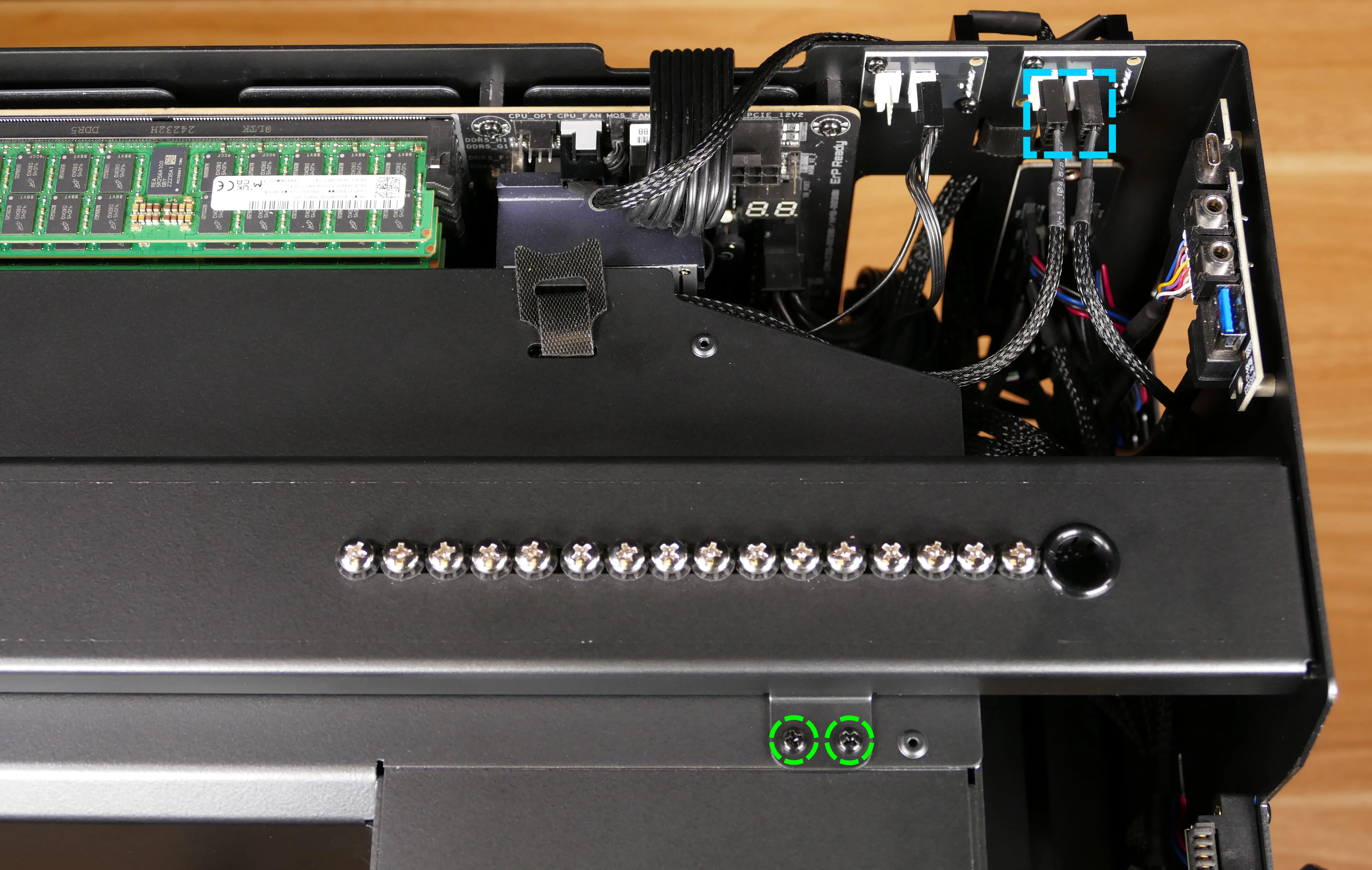
- While holding the CPU duct up, unscrew the two top screws connecting it to the top crossbar, highlighted green above.
- Pull the CPU duct out of the machine.
Replacing a GPU:
Thelio Mega R4-N3 contains four PCI Express 5.0 x16 slots. Factory configurations are offered with up to three GPUs. Four GPUs may function, depending on space and power constraints.
Tools required: Cross-head (Phillips) screwdriver
Time estimate: 15 minutes
Difficulty: Easy ●
Steps to replace a GPU:
- Follow the steps above to remove the top case, remove the side fan mount, remove the GPU brace.
- To access the top PCIe slot (which is the primary GPU slot), also remove the CPU duct.
- If you're removing a GPU, unplug the GPU power cable from the right side of the card. Hold down the latch on the connector while unplugging the cable.

- Loosen the two back screws holding the PCIe bracket in place, then slide the PCIe bracket open.
- You can optionally remove the screws and PCIe bracket instead.

- Press the latch on the motherboard to free the PCIe connection, then pull the card out of the slot.
- The top PCIe slot (the primary GPU slot) can also be freed by pressing the square quick-release button above the M.2 heatsink, highlighted red below.

- When installing new GPUs, utilize the top slot first. Other slots can be utilized in the order that best fits the GPUs, since they all run at equal bandwidth.
- After inserting the new GPU into its slot, connect the power cables.
- The maximum number of power cables are preinstalled in your system, but some may be secured with velcro straps within the PSU chamber if they weren't used in the factory configuration.
- Once all GPUs are installed, replace the back PCIe bracket, CPU duct, GPU brace, side fan mount, and top case.
Replacing the M.2 drives:
Thelio Mega R4-N3 has four M.2 slots, which all support PCIe NVMe Gen 5 x4.
Tools required: Cross-head (Phillips) screwdriver
Time estimate: 23 minutes
Difficulty: Medium ●
Steps to replace the M.2 drives:
- Follow the steps above to remove the top case, remove the side fan mount, remove the GPU brace, and remove the GPUs.
- Remove the M.2 heatsink by rotating the latch clockwise, then holding the latch down while pivoting the heatsink away from the latch.
- It may take some pressure to break the seal of the thermal tape; pull slowly to avoid breaking the thermal tape.
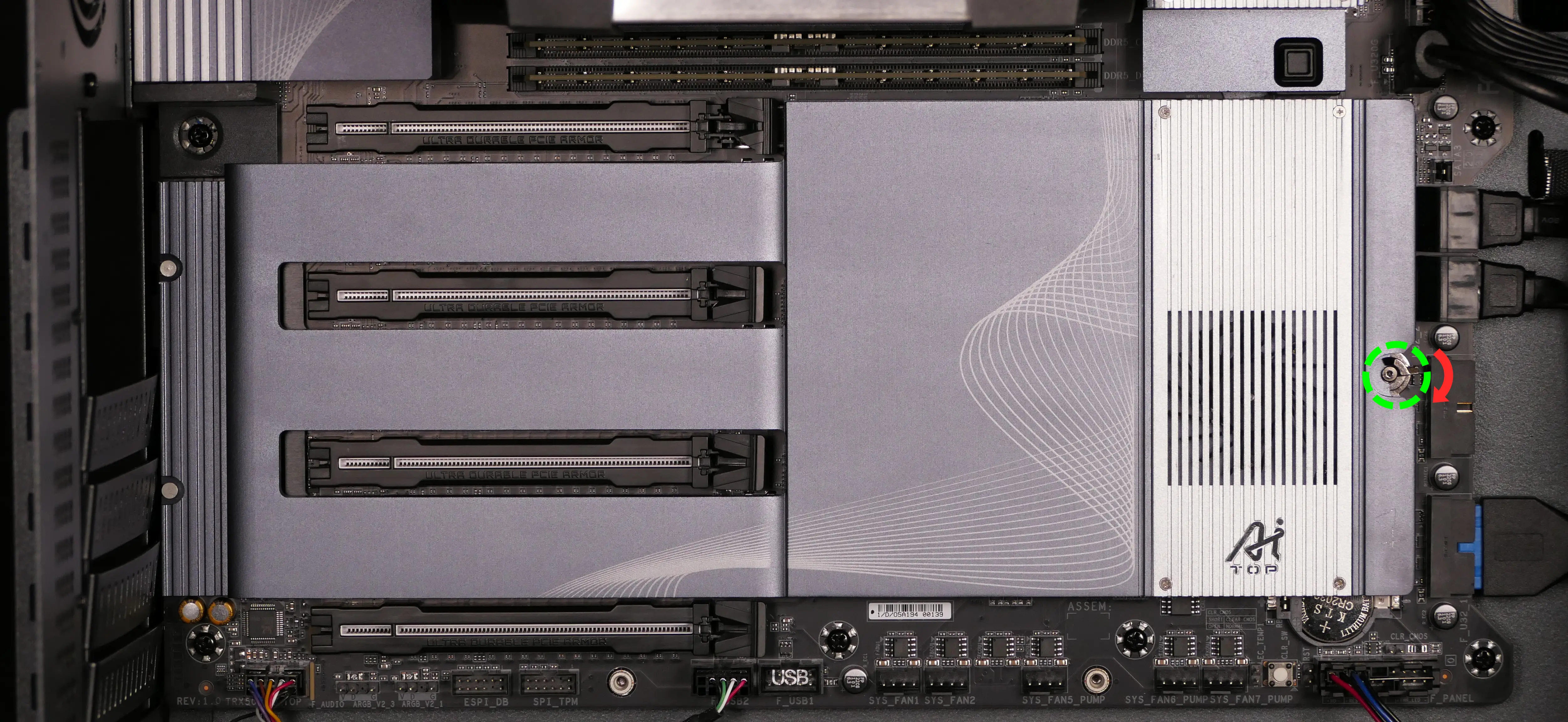
- To remove an M.2 drive, rotate the latch, pull the end of the M.2 drive slightly away from the thermal tape on the motherboard, then pull the drive out of the slot.
- The drive may lift away from the motherboard on its own if the thermal tape is not present.
- Thermal tape is not present behind Slot D.

- If utilizing a slot for the first time, peel the plastic covering off of the thermal tape behind the slot on the motherboard, and off of the thermal tape in the corresponding position on the heatsink.
- Thermal tape is not present behind Slot D on the motherboard (but is present for Slot D on the heatsink).
- In the below photos, Slots C and D have thermal tape that's ready to use, while Slots A and B still have the plastic coverings applied.
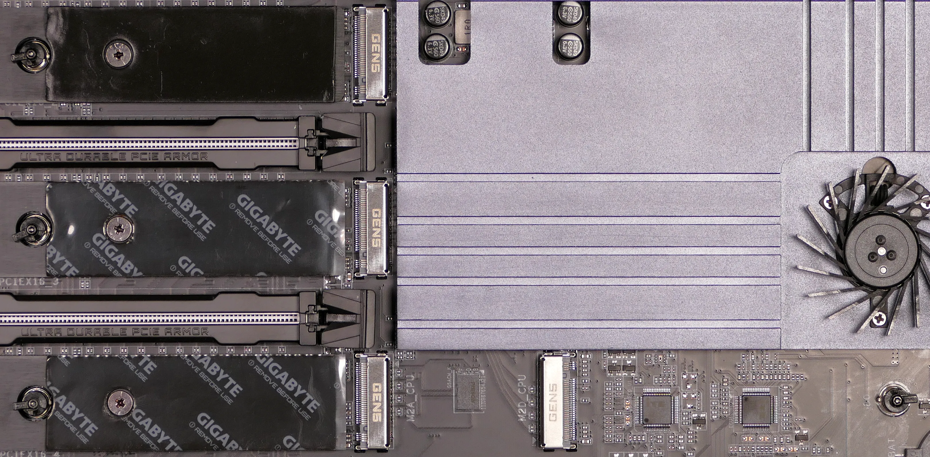
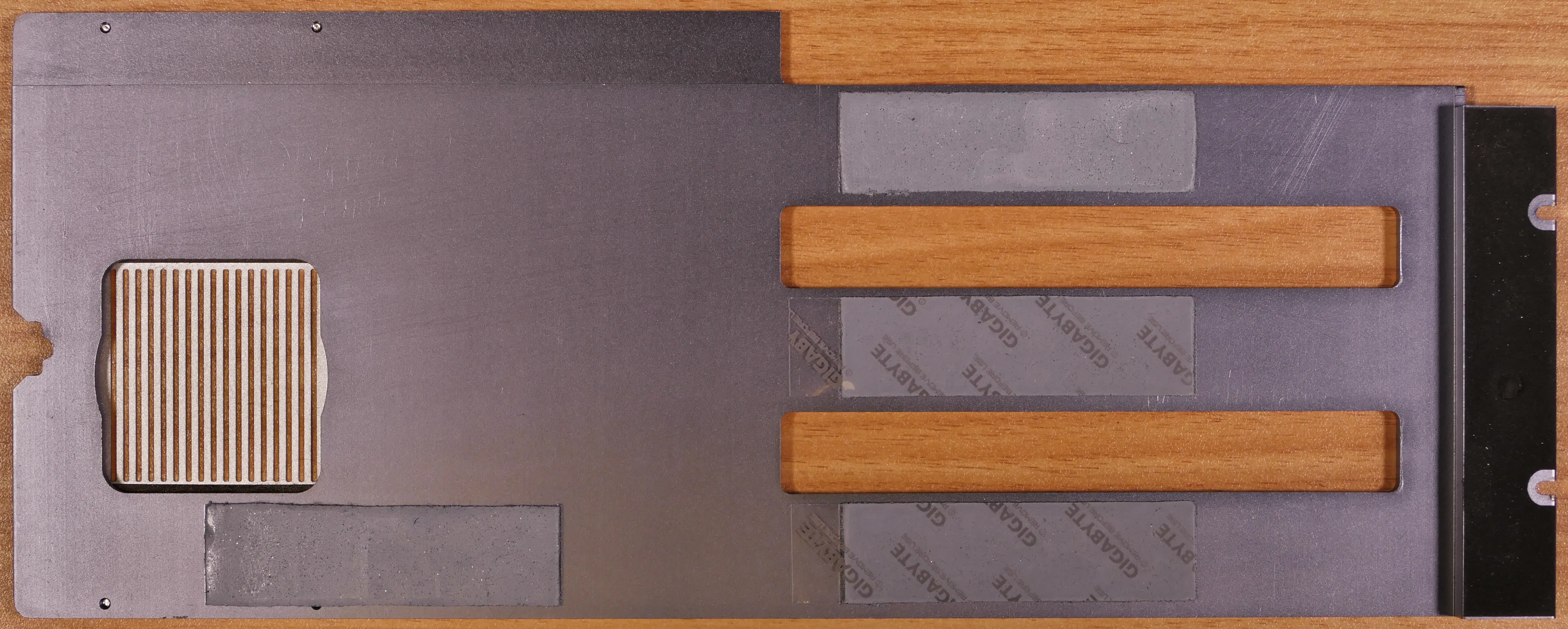
- To install an M.2 drive, insert its keyed end into the slot, then press the opposite end down onto the latch until it clicks into place.
- If the latch does not rotate on its own when the drive is pressed down, rotate it manually to allow the drive to be seated underneath it.
- Replace the M.2 heatsink, GPU(s), CPU duct, GPU brace, side fan mount, and top case.
Replacing the CMOS battery:
The CMOS battery supplies power to the system's CMOS chip. UEFI settings and the computer's hardware clock are stored on the CMOS. If your system doesn't boot, you can reset the CMOS to force a low-level hardware reset. If your clock is constantly resetting, it's likely your CMOS battery needs to be replaced.
Warning (ingestion hazard): Keep batteries out of reach of children. Death or serious injury can occur if ingested. If a battery is suspected to be swallowed or inserted inside any part of the body, seek immediate medical attention. In the US, you can also call the National Battery Ingestion Hotline for guidance: +1 (800) 498-8666
Part numbers:
- The CMOS battery is a standard KTS CR2032 battery.
Tools required: Cross-head (Phillips) screwdriver, plastic spludger tool
Time estimate: 27 minutes
Difficulty: High ●
Steps to replace the CMOS battery:
- Follow the steps above to remove the top case, remove the side fan mount, remove the GPU brace, remove the GPUs, and remove the M.2 heatsink.
- Use a small plastic tool to pry the CMOS battery out of the slot from the right side.

- Insert the new CMOS battery into the slot with the rounded side facing inward and the label facing outward.
- Reinstall the M.2 heatsink, GPUs, GPU brace, side fan mount, and top case.
Replacing the CPU fans:
Thelio Mega R4-N3 contains four CPU fans: two mounted in the CPU duct, and two mounted on the CPU cooler heatsink.
Part numbers:
- CPU duct fans: 2x Be Quiet! Silent Wings 4 (
BQ SIW4-12025-MF-PWM) - CPU cooler heatsink fans: 2x Arctic Freezer 4U fans
- Included with the Arctic Freezer 4U-M CPU cooler
Tools required: Cross-head (Phillips) screwdriver
Time estimate: 25 minutes
Difficulty: Medium ●
Steps to replace the duct-mounted CPU fans:
- Follow the steps above to remove the top case, remove the side fan mount, remove the GPU brace, and remove the CPU duct.
- Free the cables from the velcro strap on the top of the CPU duct.
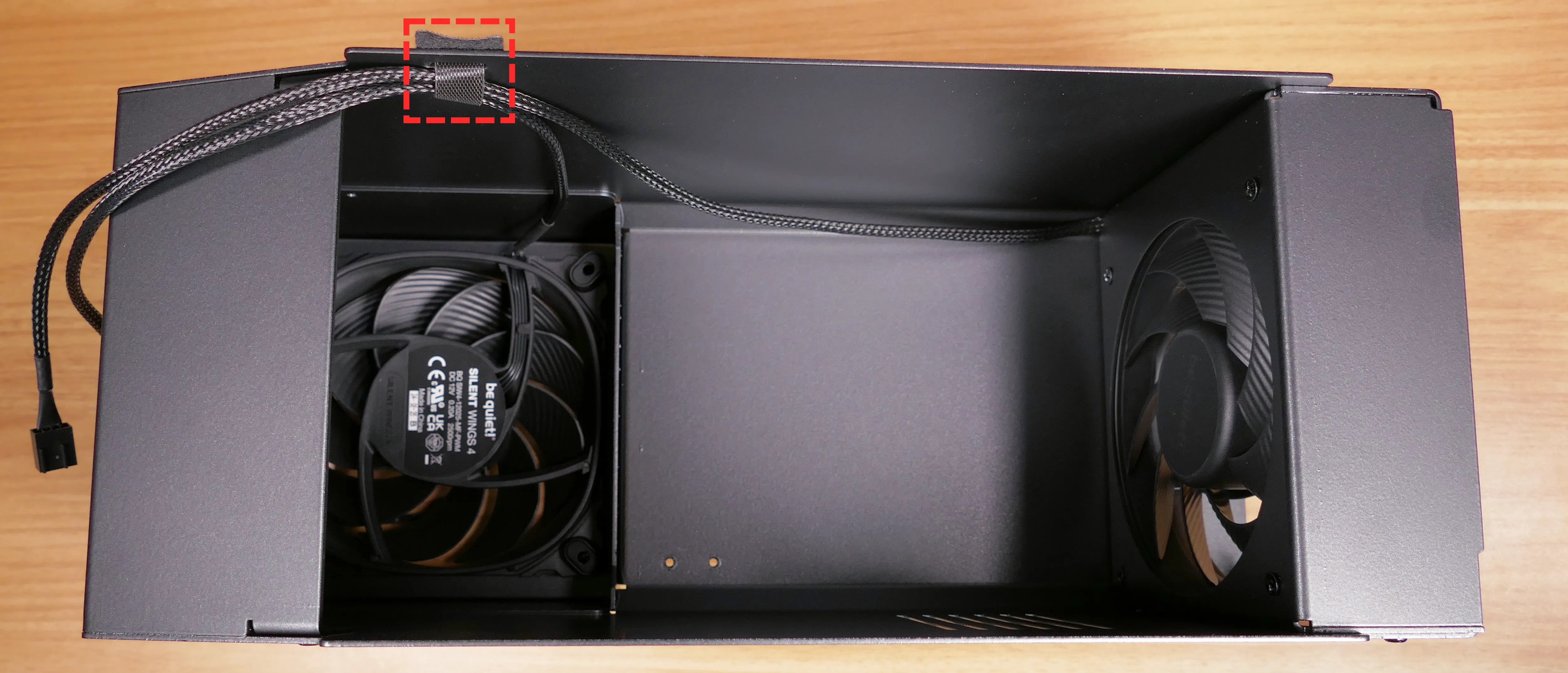
- To remove the side CPU duct fan, unscrew the four fan screws from the outside of the CPU duct.
- When reinstalling the fan, the spinning side faces outward, and the cable goes on the corner closest to the velcro strap.
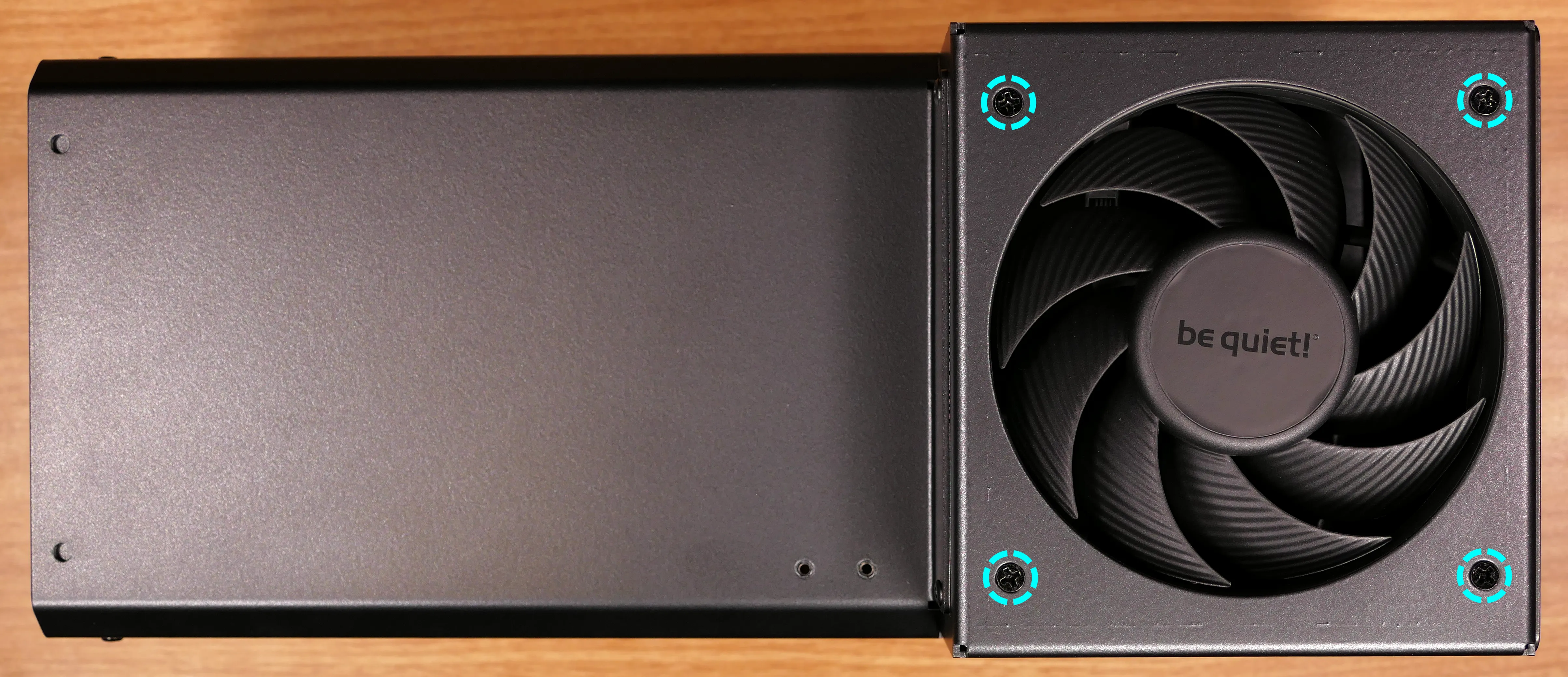
- To remove the back CPU duct fan, unscrew the four screws holding the fan bracket into the duct (two on the top, and two on the bottom).
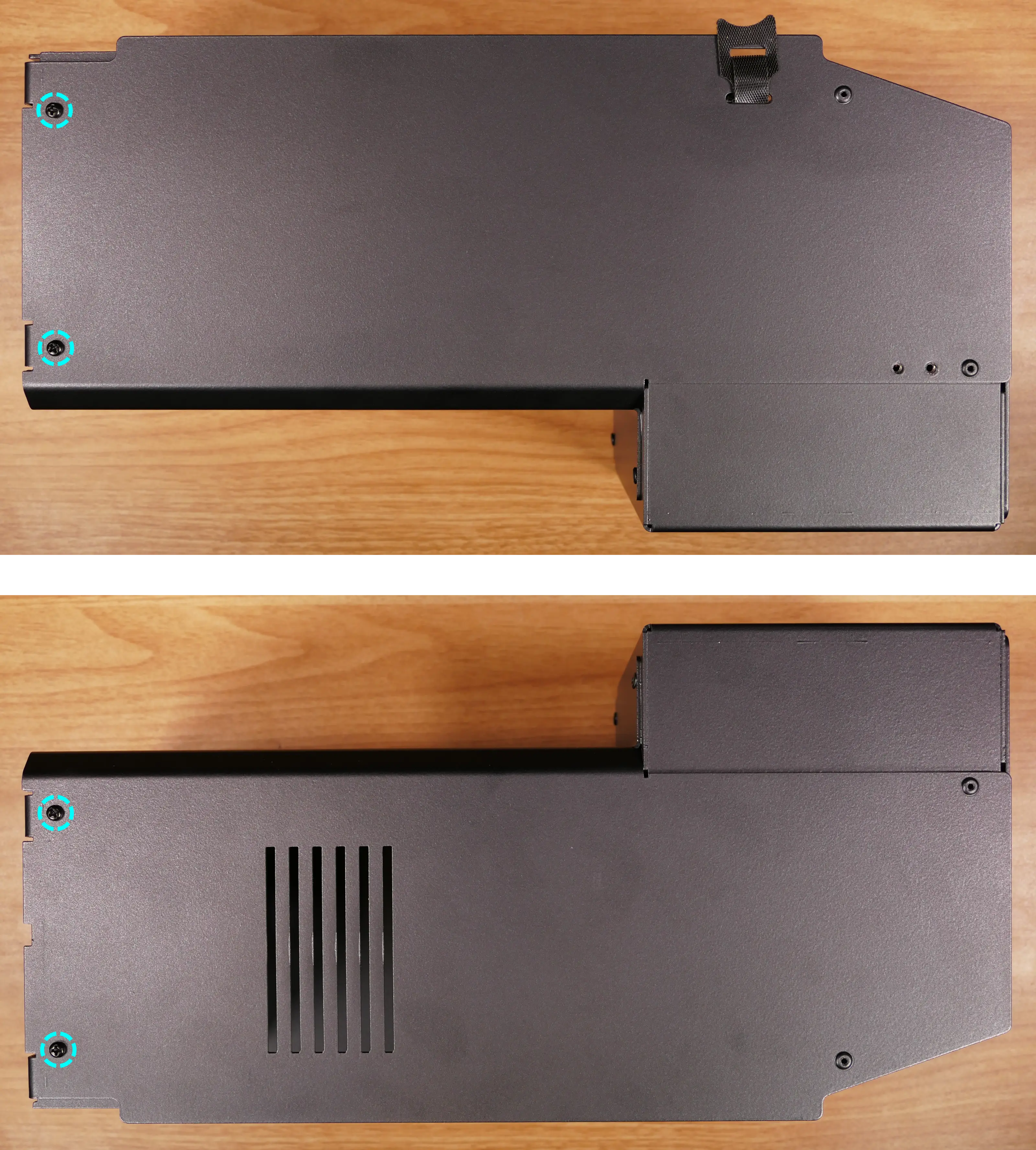
- Push the fan bracket slightly into the duct, then pull it out the side of the duct.
- Unscrew the four fan screws from the fan bracket to remove the fan.
- When reinstalling the fan, the spinning side should face into the CPU duct, with the bracket's cable cutout closest to the velcro strap.
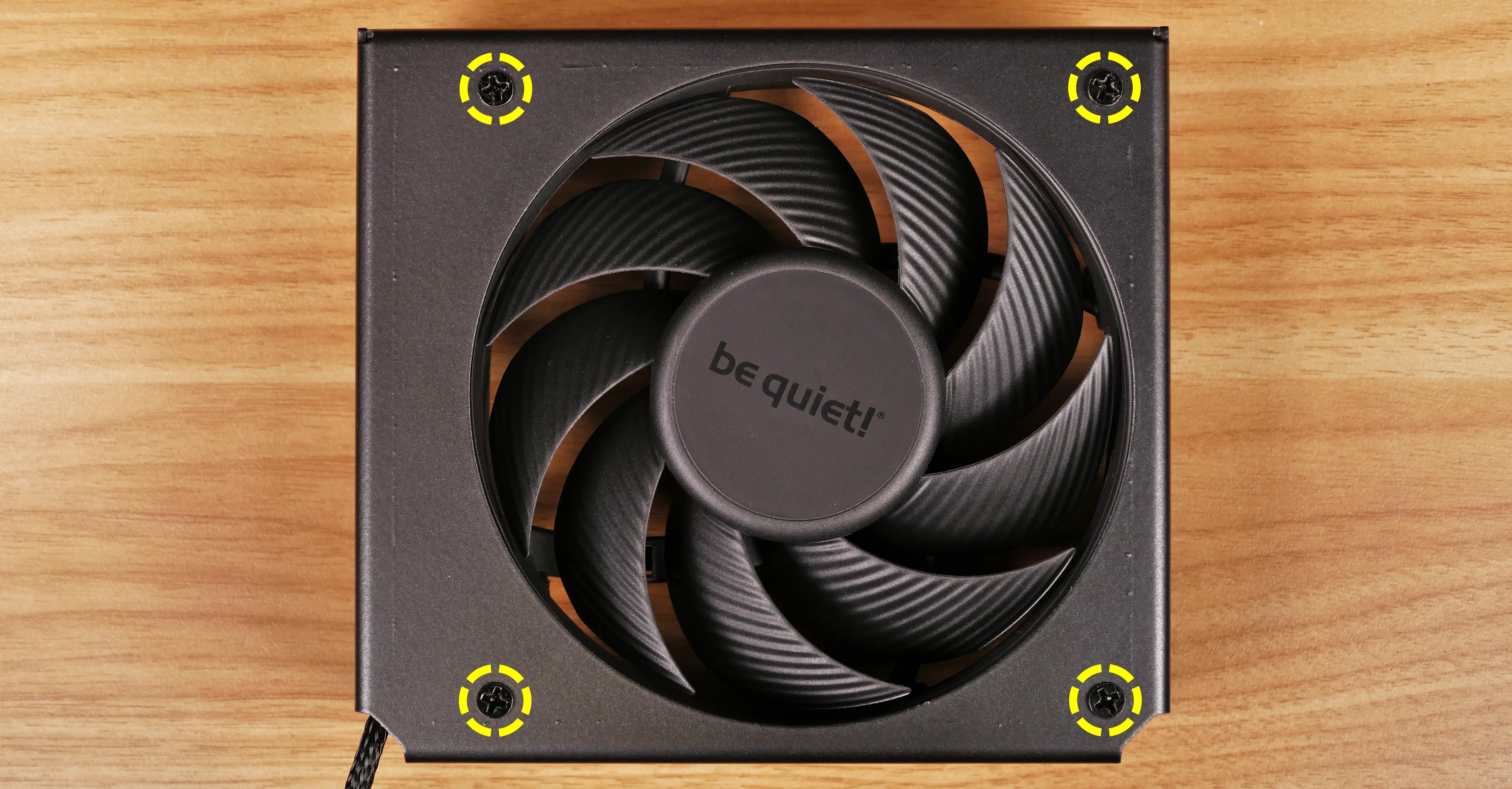
Steps to replace the cooler-mounted CPU fans:
- Follow the steps above to remove the top case, remove the side fan mount, remove the GPU brace, and remove the CPU duct.
- Disconnect the rear cooler fan from the front cooler fan's Y-cable, and unplug the front cooler fan's Y-cable from the splitter board.
- The heatsink fan cable connection points are highlighted red below.
- In the below photo, the GPU and top crossbar have been removed for better visibility.

- Pull the fans (highlighted green above) directly out of the case, sliding them off the heatsink.

- When reinstalling the CPU heatsink fans, the fan with a normal cable goes on the back of the heatsink, while the fan with a Y-cable goes on the front.
Replacing the CPU cooler and CPU:
The CPU cooler dissipates heat from the CPU to the heatsink, where the CPU fans expel it from the system. Depending on your climate and the age of the machine, replacing the thermal paste between the CPU and the cooler/heatsink may help the system run cooler. The thermal paste should generally also be replaced whenever the CPU cooler is removed from the CPU for any reason.
Part numbers:
- CPU cooler: Arctic Freezer 4U-M
- CPU socket: AMD sTR5 socket
Tools required: Cross-head (Phillips) screwdriver (long), AMD Threadripper torque tool or compatible 1.5 Nm (13.275 in-lb) torque 3.95mm six-point star (Torx 20) screwdriver, thermal paste
Time estimate: 35 minutes
Difficulty: High ●
Steps to remove the CPU cooler/thermal paste:
- Follow the steps above to remove the top case, remove the side fan mount, remove the GPU brace, remove the CPU duct, and remove the cooler-mounted CPU fans.
- While holding the cooler in place so it doesn't fall, loosen the four CPU cooler screws.
- The screws are held captive and will not fully detatch from the cooler.

- The cooler will come away from the CPU.
- Using a paper towel, clean the existing thermal paste off of the heatsink and CPU.
- Due to the design of the heatsink, some thermal paste may remain between the heatsink pipes. Only the flat section of the pipes that makes contact with the CPU needs to be cleaned.
- You may also use a small amount of rubbing alcohol if the old paste is dried or difficult to remove.
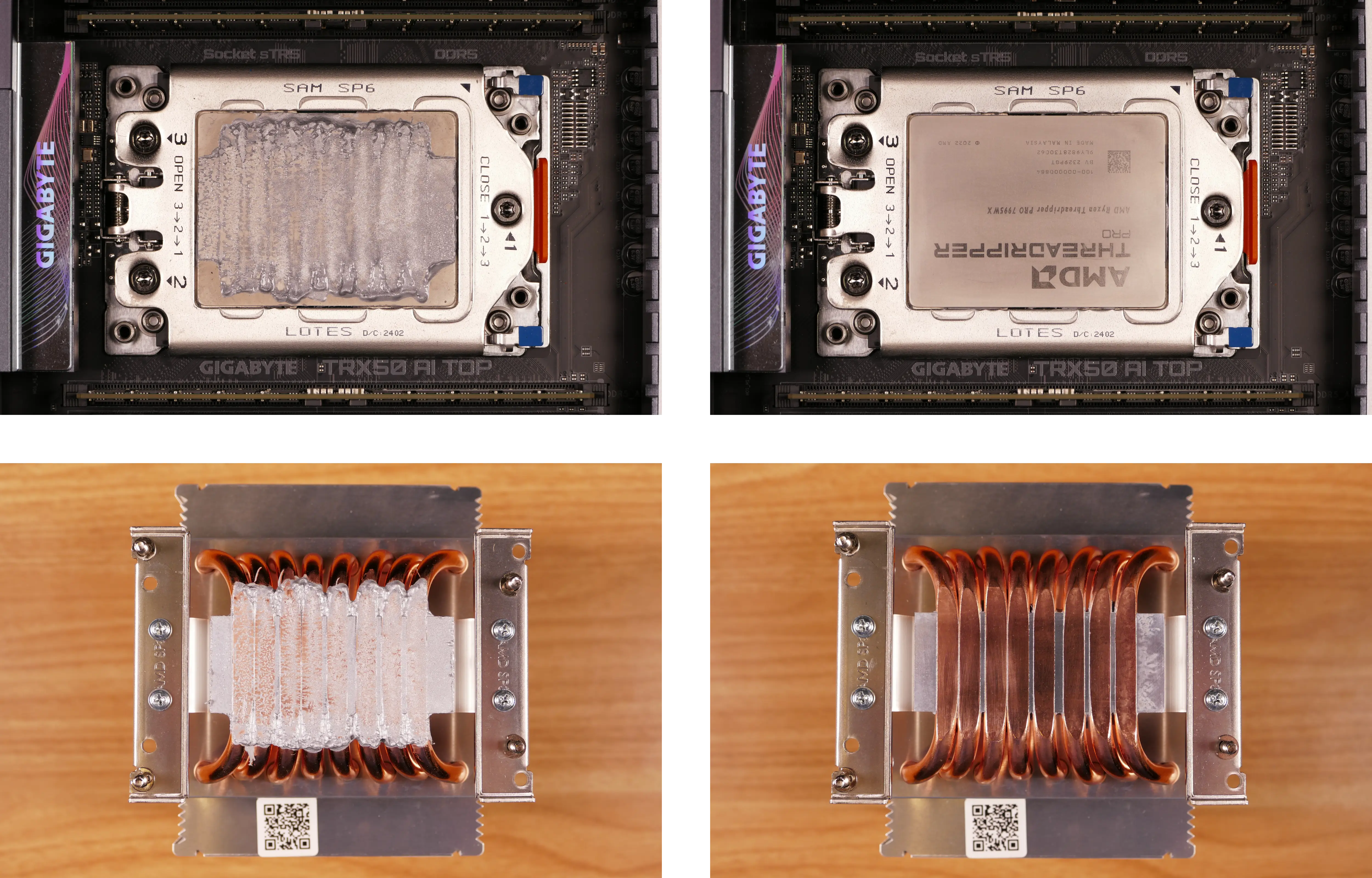
Steps to replace the CPU:
- Place the computer on its side so the motherboard is facing up.
- Using the AMD Threadripper torque screwdriver (or a compatible T20 screwdriver), loosen the three CPU bracket Torx screws in reverse order of the printed numbers (starting with #3).
- The screws are held captive and will not come out of the bracket.

- The CPU bracket cover will spring up when all its screws are fully loosened.
- If the bracket cover only partially opens, you may need to loosen screws #2 and/or #3 more.

- Using the blue corner tabs (visible above), flip the orange CPU carrier frame up and away from the CPU socket.

- Slide the CPU carrier tray out of the CPU bracket.
- Be careful not to bend any of the gold pins on the CPU socket, and do not touch the gold pads on the CPU.

- Slide the new CPU's carrier tray into the CPU bracket.
- AMD Threadripper CPUs come with carrier trays, so removing the CPU from the tray is generally not necessary.
- Flip the CPU bracket back down onto the socket, gently pressing the blue tabs to seat the CPU carrier tray onto the motherboard.
- Flip the CPU bracket cover back down.
- Screw the three Torx screws back into place in order of the printed numbers (starting with #1).
- The AMD Threadripper-branded tool applies 1.5 Nm of torque. When the screw is tight enough, it will give way.
- If you're using a different screwdriver, use a torque tool to apply approximately the same amount of torque (1.5 Nm, or ~13.275 in-lb).
- If you're using a screwdriver without a torque tool, try to tighten all three screws evenly. After re-assembling the computer, run a RAM test to ensure the CPU is secured with the correct amount of force.
Steps to install the thermal paste/CPU cooler:
- Draw an
Xshape of thermal paste onto the CPU.

- Place the CPU cooler onto the CPU; while holding it in place, tighten the four screws.
- The two screws on the left side use the outer holes; the two screws on the right side use the inner holes.
- The air flow arrows stamped into the top of the heatsink should point towards the back of the chassis.
- Insert each screw partially, then finish tightening both.
- Set the computer upright, then reinstall the cooler-mounted CPU fans, CPU duct, GPU brace, side fan mount, and top case.
Replacing the RAM:
Thelio Mega R4 supports up to 512GB (8x64GB) of ECC DDR5 RAM DIMMs running at a maximum speed of 5600 MHz. If you've purchased new RAM, need to replace your RAM, or are reseating your RAM, follow these steps.
Tools required: Cross-head (Phillips) screwdriver
Time estimate: 17 minutes
Difficulty: Medium ●
Steps to replace the RAM:
- Follow the steps above to remove the top case, remove the side fan mount, remove the GPU brace, and remove the CPU duct.
- You can optionally remove the CPU cooler for easier access to the innermost RAM slots; it's been removed for better visibility in the below photo.
- To remove an existing RAM stick, flip the latches on each side away from the stick, then pull the stick out of the slot.

- Make sure the tabs on the left and right of the slot are open (pulled outwards), then insert the new RAM (or re-seat the existing RAM) into the slot.
- The RAM stick will only fit in one direction. The larger group of pins goes on the right side.
- Use the following guide for placement of the RAM sticks:

- Replace the CPU cooler (if necessary), CPU duct, GPU brace, side fan mount, and top case.
Opening the PSU chamber:
The PSU chamber houses the power supply unit (PSU) and its related cabling, and provides a mounting point for the bottom intake fan.
Tools required: Cross-head (Phillips) screwdriver
Time estimate: 12 minutes
Difficulty: Medium ●
Steps to open the PSU chamber:
- Follow the steps above to remove the top case, remove the side fan mount, and remove the GPU brace.
- Unplug the power cables from all installed GPUs.
- Unscrew the four side screws holding the PSU chamber's cover on.
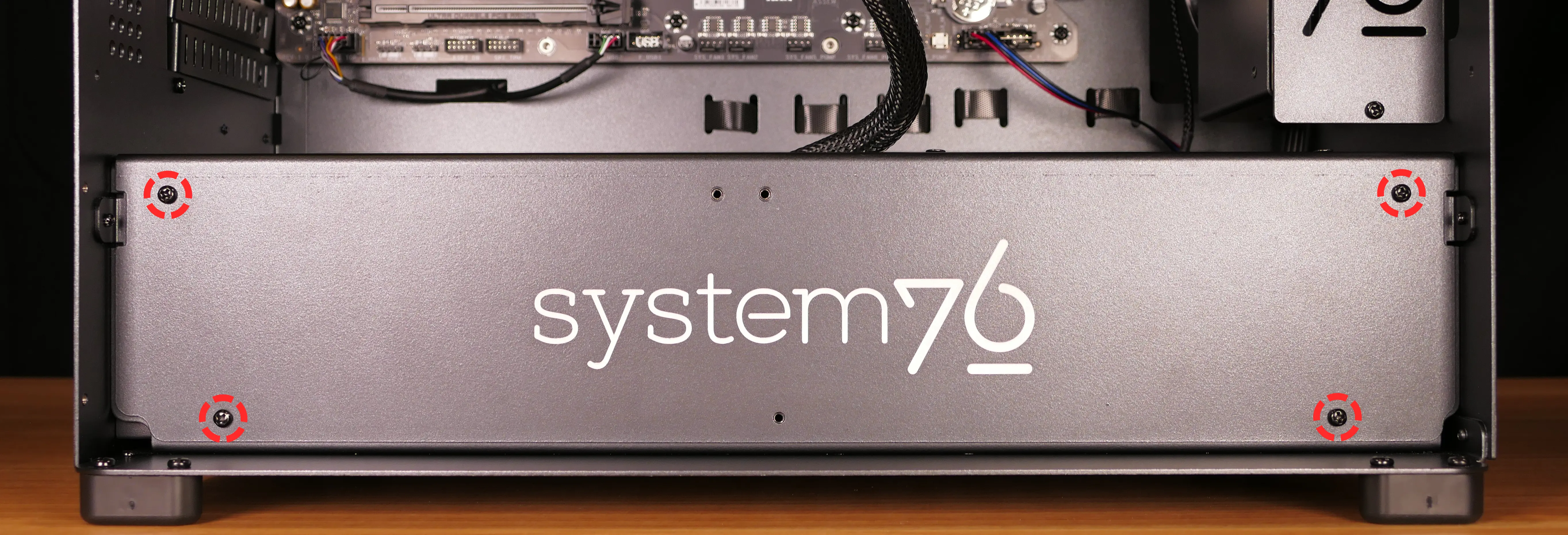
- Pull the cover off of the PSU chamber.
- The bottom intake fan's cable does not need to be untied to access the inside of the PSU chamber, but can be untied for easier access.
Replacing the bottom intake fan:
The 140mm bottom intake fan can be independently replaced.
Part numbers:
- The bottom intake fan is a 140mm Be Quiet! Silent Wings 4 (model number
BQ SIW4-14025-MF-PWM).
Tools required: Cross-head (Phillips) screwdriver
Time estimate: 18 minutes
Difficulty: Medium ●
Steps to replace the bottom intake fan:
- Follow the steps above to remove the top case, remove the side fan mount, remove the GPU brace, and open the PSU chamber.
- Free the cable from the velcro loop (near the power button receptacle) and unplug it from the Thelio Io board.

- Unscrew the four screws holding the fan onto the top cover of the PSU chamber.

- Screw in the new fan.
- The fan should be oriented so the cable is closest to the cable cutout in the PSU chamber cover, with the spinning side facing down.
- Pass the fan's cable through the PSU chamber cover, plug the new fan into the
INTAKE FAN(FANOUT2) port on the Thelio Io board, and secure the excess cabling with the velcro loop. - Close the PSU chamber and reinstall the GPU brace, side fan mount, and top case.
Replacing the power supply:
The power supply unit (PSU) is modular and can be replaced with another unit of the same model. Different models may not be compatible with the cabling pre-installed in the Thelio Mega.
Part numbers:
- The default power supply is a Thermaltake Toughpower GF3 1650W Gold.
Tools required: Cross-head (Phillips) screwdriver
Time estimate: 20 minutes
Difficulty: High ●
Steps to replace the power supply:
- Follow the steps above to remove the top case, remove the side fan mount, remove the GPU brace, and open the PSU chamber.
- Unplug all of the modular cabling from the back of the PSU.
- Some of the cables may be easier to unplug after the PSU has been unscrewed/removed from the case.
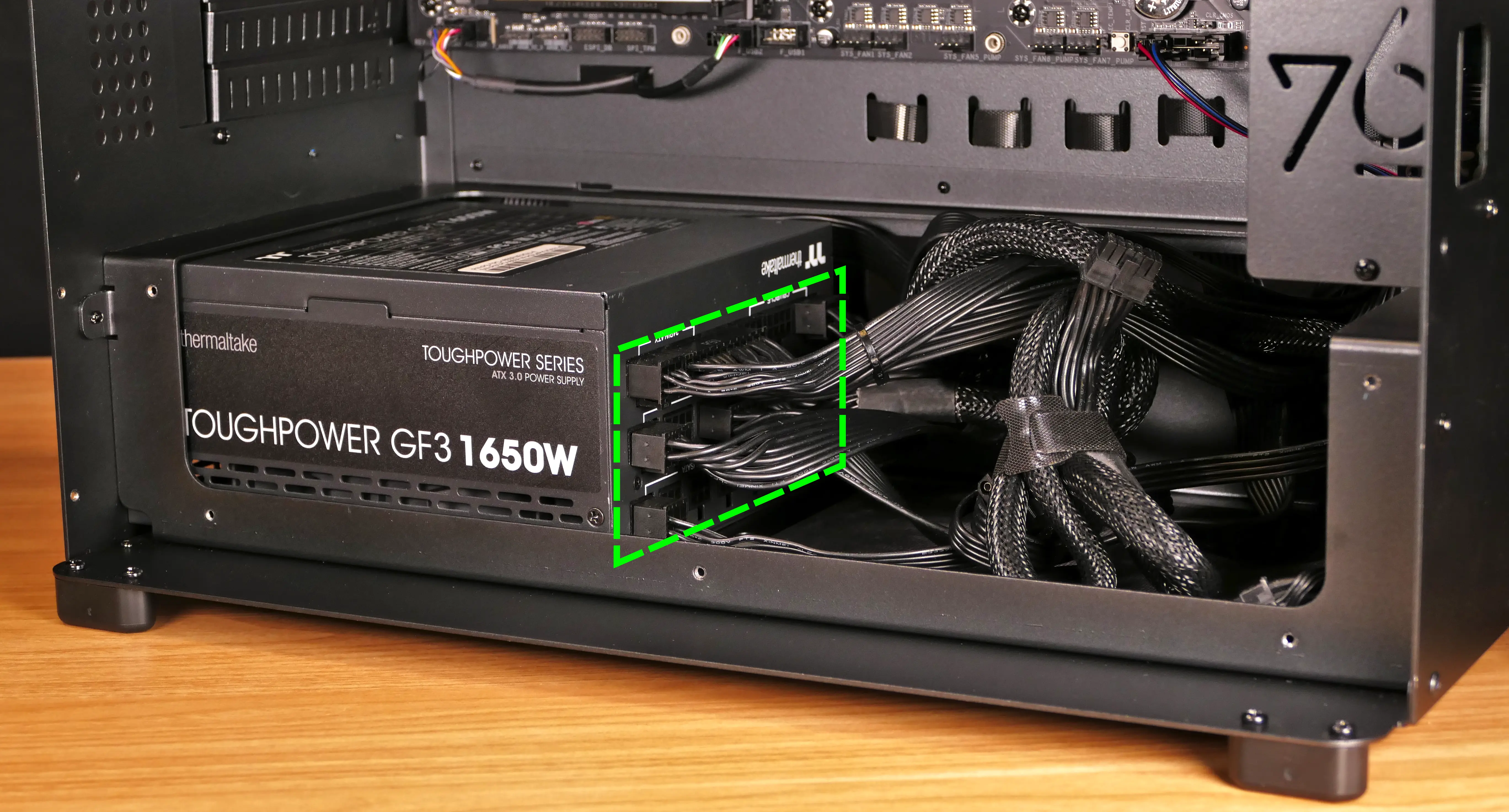
- Unscrew the four screws holding the PSU in from the back of the case.

- Slide the PSU into the chassis and then pull it out of the PSU chamber.
- Insert the new PSU, setting it on top of the rubber post that holds it at the correct height.
- The replacement PSU should be installed with the fan facing the bottom of the case.

- Screw in the replacement PSU.
- You may need to hold the PSU up to the back of the chassis to align the screwholes while inserting the screws.
- Use the labels and pin counts on the cables and ports to ensure the power cables are reconnected to the new PSU in the proper locations.
- If the replacement PSU has a "Smart Zero Fan" switch, make sure it's switched on for the optimal fan curve.
Removing the top crossbar:
The top crossbar can be replaced for repair or removed for easier access to internal components.
Tools required: Cross-head (Phillips) screwdriver
Time estimate: 3 minutes
Difficulty: Easy ●
Steps to remove the top crossbar:
- Follow the steps above to remove the top case.
- Unscrew the top crossbar from the front of the chassis.

- Unscrew the top crossbar from the back of the chassis.

- Pull the top crossbar away from the chassis.
Replacing the Thelio Io board:
Named after Jupiter's moon Io, the Thelio Io daughterboard handles the front power button and fan control. If the Thelio Io board becomes defective, it can be replaced using the instructions below.
Part numbers:
- Thelio Mega R4-N3 uses Thelio Io version 2 (PCB revision thelio_io_2.3).
Tools required: Cross-head (Phillips) screwdriver
Time estimate: 25 minutes
Difficulty: High ●
Steps to replace the Thelio Io board:
- Follow the steps above to remove the top case and remove the side fan mount.
- It's optional but recommended to also remove the GPU brace and remove the CPU duct for easier access to the cabling.
- Use the cutout on the front of the chassis to unplug all cabling from the Thelio Io board.
- The second-from-top connector (
POWER1) requires pulling the white tab while unplugging. - The bottom connector (
USB) requires holding the black clip while unplugging.
- The second-from-top connector (

- Unscrew the two screws holding the daughterboard on from the right side of the chassis.

- Screw in the new Thelio Io board and reconnect the wiring.
Thelio Io wiring guide:

-
When wiring the Thelio Io board, refer to the port labels and the following guide.
FANOUT1/CPU FAN- to the left fan splitter (connecting to the cooler-mounted CPU fans).FANOUT2/INTAKE FAN- to the bottom intake fan.FANOUT3/GPU FAN- to the side fan mount's fan splitter.FANOUT4/AUX FAN- to the right fan splitter (connecting to the duct-mounted CPU fans).FANIN1/MOTHERBOARD FAN INPUT- to theCPU_FANheader at the top right of the motherboard, highlighted cyan below.

POWER1/POWER INPUT- to the power supply via a Molex (large 4-pin) to Berg (small 4-pin) adapter cable.- The white plastic clip needs to be held away from the connector to unplug this cable from the Thelio Io board.
- The adapter cable may be a Y-cable; the other small end can be left unplugged.
PFP1/FRONT PANEL- to the power button receptacle on the front panel.- On the Thelio Io board, the wire color order (from top to bottom) is red, black, blue, black.
- On the power button receptacle, the wire color order (from left to right) is red, black, blue, black.
PMB1/MOTHERBOARD- to the first four pins of theF_PANELheader at the bottom right of the motherboard, highlighted green below.- On the Thelio Io board, the wire color order (from top to bottom) is red, black, blue, black.
- On the motherboard, the wire color order (from left to right) is red, black, blue, black.

USB- to theF_USB2header on the bottom edge of the motherboard, highlighted yellow above.- A black plastic clip needs to be held down to unplug this cable from the Thelio Io board.
- This port can alternatively be connected to the
F_USB1header on the motherboard if theF_USB2header becomes defective.
Replacing the SATA backplanes:
Each of the two SATA backplanes provides two 2.5" SATA III data and power connectors for its corresponding 2.5" drive cage.
Part numbers:
- The part number and version for the SATA backplane is thelio-io-sata_2.2.
Tools required: Cross-head (Phillips) screwdriver
Time estimate: 15 minutes
Difficulty: Medium ●
Steps to replace the SATA backplanes:
- Follow the steps above to remove the top case and remove the side fan mount, then remove the 2.5" drive cage cover and all 2.5" SATA drives in front of the backplane(s) you're replacing.
- Use the cutout on the right side of the chassis to unplug the 4-pin Berg power connector (highlighted cyan below) and the two SATA data cables (highlighted green below) from the SATA backplane(s).
- View of the cables is partially obstructed by other nearby cables.
- The white clip needs to be held away from the connector while unplugging the power cable.

- Unscrew the four screws holding the drive cage onto the chassis, then remove the drive cage from the chassis.
- The top four screws are for the top drive cage; the bottom four screws are for the bottom drive cage.
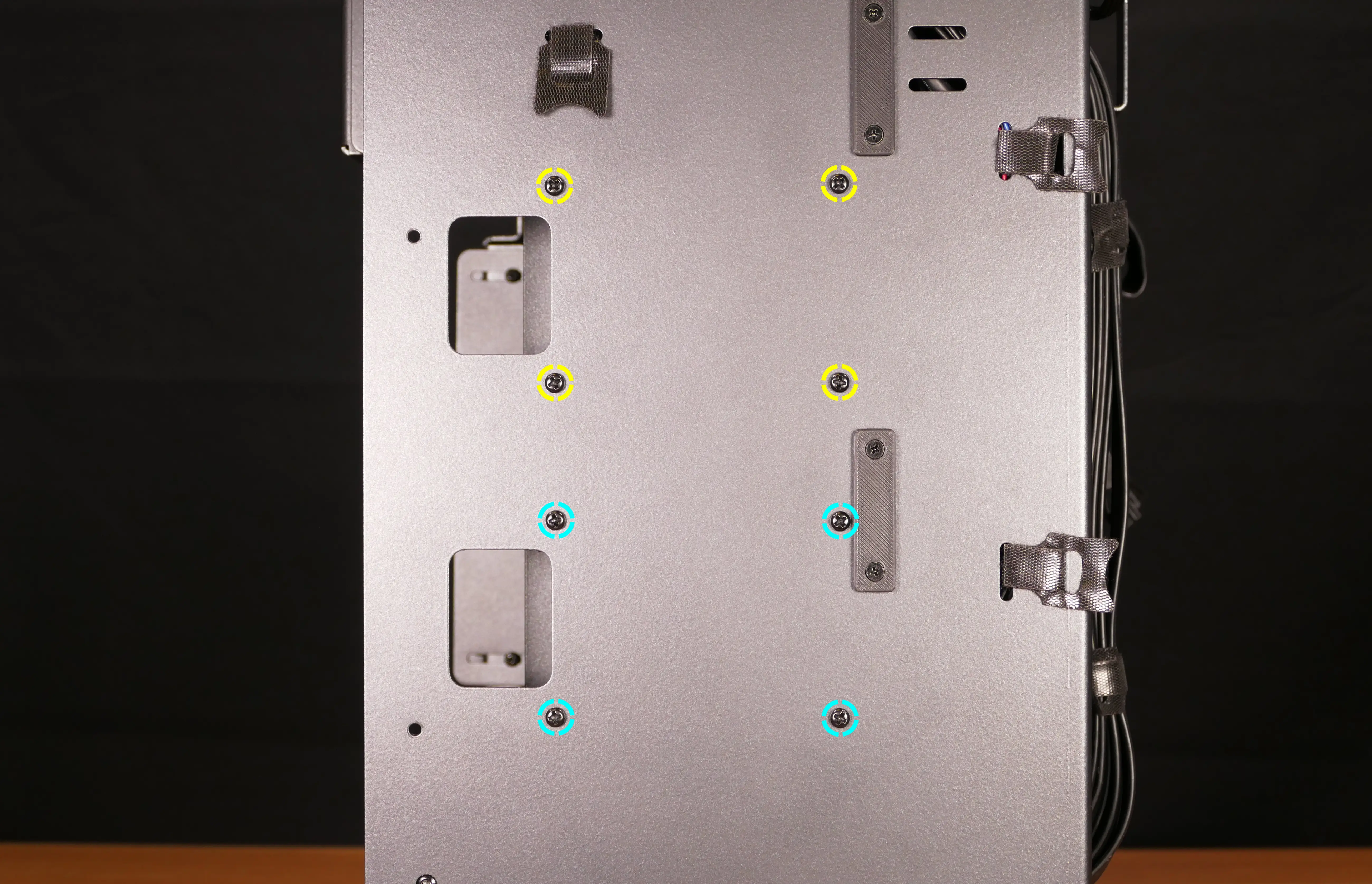
- Unscrew the four SATA backplane screws from the drive cage, then push the SATA backplane out through the front of the drive cage.

- Place the new SATA backplane into the drive cage and secure it with the four SATA backplane screws, then reinstall the drive cage.
- Plug the 4-pin Berg power connector and SATA data cables into the SATA backplane.
- The order of the SATA data cables shouldn't matter as long as your operating system and software is configured to address disks by UUID (e.g.
/dev/disk/by-id/...) instead of by letter (e.g./dev/sd_). - By default, the ports connect as follows:
- Top SATA backplane (top row of motherboard ports):
DATA0connects to motherboard port 1.DATA1connects to motherboard port 0. - Bottom SATA backplane (bottom row of motherboard ports):
DATA0connects to motherboard port 3.DATA1connects to motherboard port 2.
- Top SATA backplane (top row of motherboard ports):
- The motherboard's SATA ports can be accessed from behind via the cabling cutout. In the below photo, the GPU brace, CPU duct, and GPU have been removed to show the ports from the front.
- The order of the SATA data cables shouldn't matter as long as your operating system and software is configured to address disks by UUID (e.g.

- Reinstall the side fan mount, any 2.5" drives that were removed, the 2.5" drive cage cover(s), and the top case.
Replacing the top I/O:
Thelio Mega R4-N3 includes a top I/O module providing audio and USB ports. If the top ports are damanged or become defective, they can be replaced using the steps below.
Part numbers:
- The top I/O module's part number is
MYS7523 Rev. 4.0.
Tools required: Cross-head (Phillips) screwdriver
Time estimate: 20 minutes
Difficulty: Medium ●
Steps to replace the top I/O:
- Follow the steps above to remove the top case, remove the CPU duct, and remove the side fan mount.
- Unplug the
F_AUDIOheader at the bottom-left corner of the motherboard, highlighted cyan below.

- Unplug the
F_U32_1header near the bottom-right corner of the motherboard, highlighted red above. - Unplug the
F_U320Gheader near the right side of the motherboard just above the graphics card and M.2 heatsink, highlighted green below.
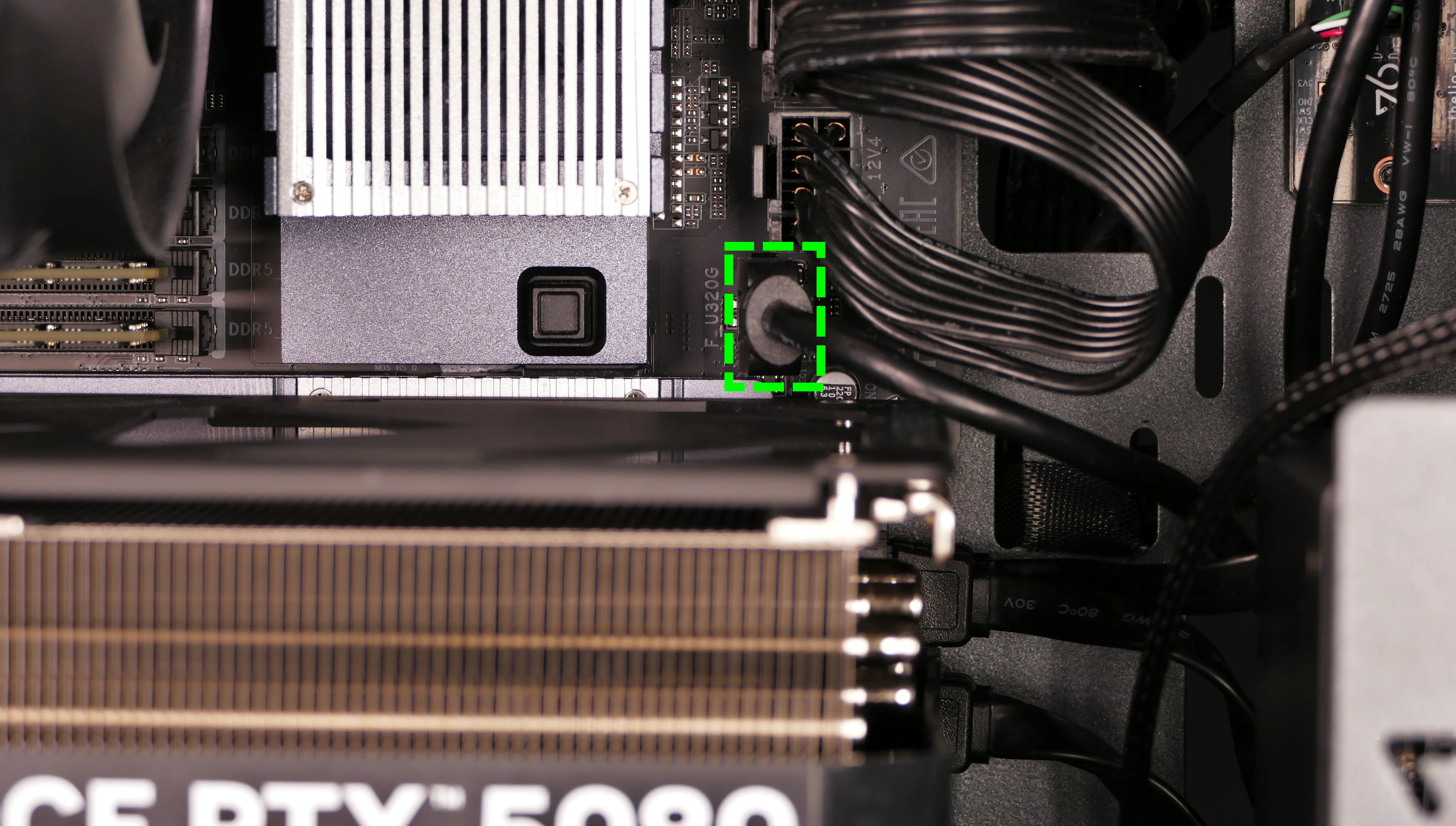
- Unscrew the two front screws holding the top I/O board onto the chassis.

- Remove the top I/O board from the system.
- Insert the new top I/O board into the system and screw it into place.
- Reconnect the audio and USB headers.
- Replace the side fan mount, CPU shroud, and top case.
Troubleshooting the power button:
If the front power button doesn't power the machine on or doesn't light up when the system is powered on, try the following troubleshooting steps:
- Ensure the system powers on normally using the internal power button.
- Reseat the front power button to ensure it's making proper contact.
- Check the wiring for the front power button.
- Replace the front power button, if necessary.
Tools required: Cross-head (Phillips) screwdriver
Time estimate: 20 minutes
Difficulty: Medium ●
Steps to power the machine on using the internal power button:
- Follow the steps above to remove the top case.
- Ensure the system is plugged into power, and the power supply switch is in the 1 (On) position.
- Push the small button labeled
POWERon the Thelio Io board.

- If the Thelio Io
POWERbutton powers the machine on, then the issue is either the front power button or its connection to the Thelio Io board. Check the front power button wiring. - If the Thelio Io
POWERbutton does not work, press the power (⏻) button near the top right of the motherboard.- The CPU duct has been removed in the below photo for better visibility, but does not need to be removed to reach the motherboard power (
⏻) button.
- The CPU duct has been removed in the below photo for better visibility, but does not need to be removed to reach the motherboard power (
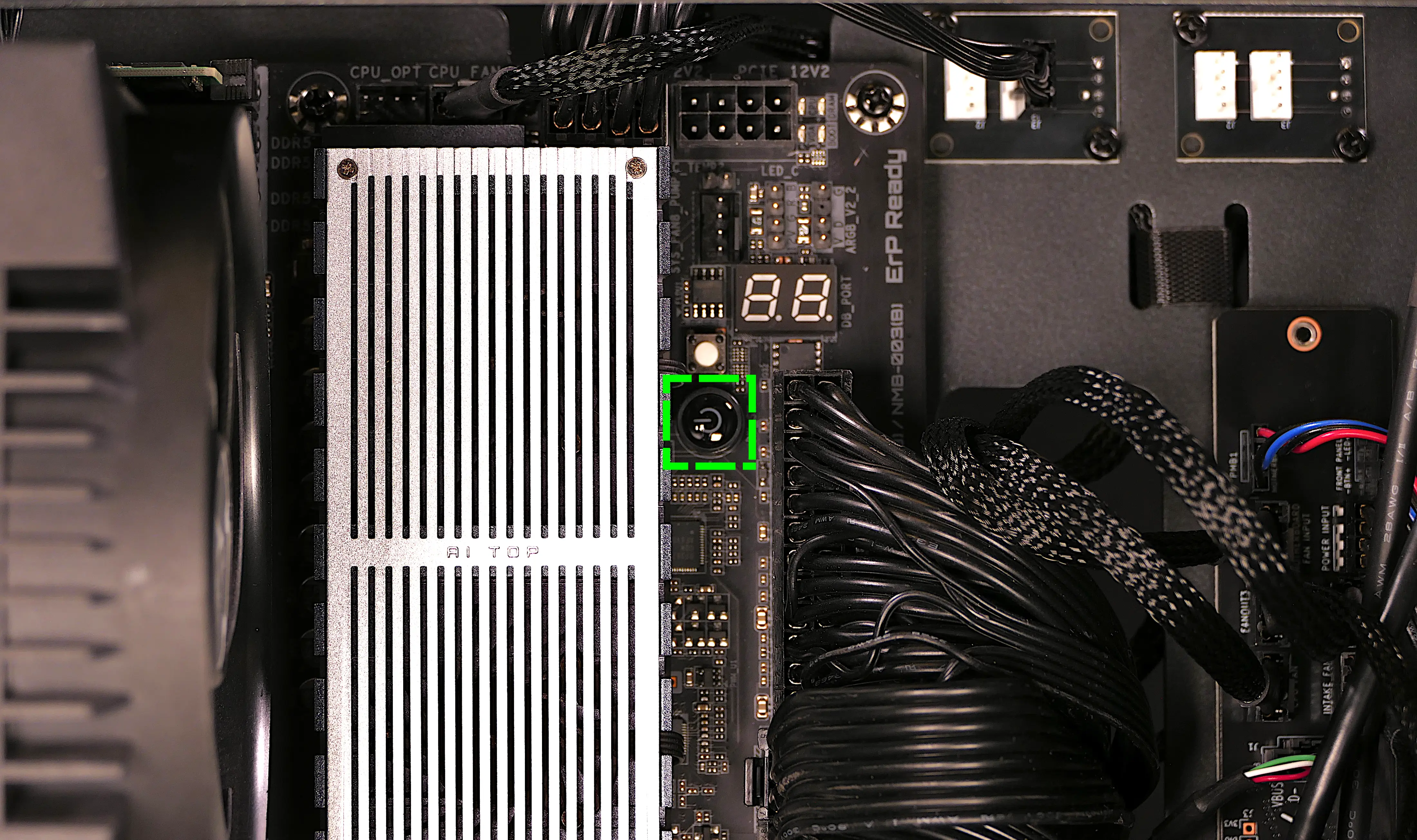
- If the motherboard power (
⏻) button works, but the Thelio IoPOWERbutton does not work, then the issue is either the Thelio Io board or its connection to the motherboard. Check the wiring between the Thelio Io board and the motherboard. - If the motherboard power (
⏻) button does not work, then the issue may be the motherboard, or it may be the power supply or its connection to the motherboard. Ensure all connectors are plugged in properly and that the power supply is switched to the 1 (On) position.
Steps to check the front power button wiring:
- Follow the steps above to remove the top case.
- You can optionally remove the CPU duct for easier access to the power button receptacle and its wiring.
- On the back of the power button, the four pins should be connected to the four-wire connector as follows:

- On the front power button receptacle, the four-pin connector should have the red wire on the left and the black wire on the right.

- The front power button receptacle should plug into the PFP1 port on the Thelio Io board, with the red wire on the top (see the Thelio Io wiring guide).
Steps to replace the power button:
- Follow the steps above to remove the top case.
- Follow the instructions in the Replace the Thelio Power Button support article.
Thelio Mira (thelio-mira-r4-n3)
The System76 Thelio Mira is a desktop with the following specifications:
- Processor options
- Supports AMD Ryzen 9000 series (Granite Ridge) CPUs
- Motherboard
- ASRock X870 Pro RS WiFi running System76 Firmware (non-open)
- AMD X870 chipset
- Daughterboard
- Thelio Io board running open-source firmware
- Graphics options
- Ships with up to one dedicated GPU
- Primary GPU slot:
- PCIe 5.0 x16
- Up to 4-slot height
- Primary GPU slot:
- GPU size:
- Internal clearance: 358mm
- Recommended maximum length: 348mm
- Tested with the following GPUs:
- Integrated Graphics
- 1x HDMI 2.1
- 2x DisplayPort 1.3 via USB-C
- NVIDIA GeFroce RTX 5090 (requires 1000W PSU)
- 1x HDMI 2.1b
- 3x DisplayPort 2.1b
- NVIDIA GeForce RTX 5080
- 1x HDMI 2.1b
- 3x DisplayPort 2.1b
- NVIDIA GeForce RTX 5070 Ti
- 1x HDMI 2.1b
- 3x DisplayPort 2.1b
- NVIDIA GeForce RTX 5060 Ti
- 1x HDMI 2.1b
- 3x DisplayPort 2.1b
- NVIDIA GeForce RTX 5050
- 1x HDMI 2.1b
- 3x DisplayPort 2.1b
- AMD Radeon RX 9070 XT
- 1x HDMI 2.1b
- 3x DisplayPort 2.1a
- Integrated Graphics
- Ships with up to one dedicated GPU
- Expansion
- 1x PCIe 5.0 x16 (primary GPU slot)
- Up to 4-slot height
- 1x PCIe 4.0 x4
- Fits physical x16 cards, runs at x4 bandwidth
- Up to 2-slot height
- Disabled if second M.2 drive is installed
- 1x PCIe 5.0 x16 (primary GPU slot)
- Memory
- Up to 192GB (4x48GB) dual-channel DDR5 DIMMs
- 192GB (4x48GB) and 128GB (4x32GB) configurations run at 3200 MHz
- 96GB (2x48GB) configuration runs at 6400 MHz
- 64GB (2x32GB) and 32GB (1x32GB) configurations run at 5600 MHz
- Motherboard supports up to 256GB (4x64GB) @ 8000+ MHz w/ overclocking (not tested)
- Tested with the following RAM modules (may ship with other tested modules):
- Team CTCED596G6400HC32ADC01 (48GB/stick @ 6400 MHz)
- G.Skill F5-6400J3239F48GX2-RS5K (48GB/stick @ 6400 MHz)
- Crucial CT32G56C46U5 (32GB/stick @ 5600 MHz)
- Up to 192GB (4x48GB) dual-channel DDR5 DIMMs
- Networking
- 1x 2.5-Gigabit Ethernet (Realtek RTL8125BG)
- Wi-Fi 7 + Bluetooth 5.2 (MediaTek MT7927 or MediaTek MT7925)
- Power
- C13 power cord
- 850W minimum PSU
- Some GPU configurations require 1000W PSU
- Tested with the following PSU models (may ship with other tested models):
- Sound
- 3.5mm line out, line in, microphone jacks
- Up to 7.1-channel audio output
- Realtek ALC1220 audio chipset
- HDMI, DisplayPort, USB-C DisplayPort audio (depending on GPU)
- Storage
- 1x M.2 (PCIe NVMe Gen 5) SSD
- 1x M.2 (PCIe NVMe Gen 4) SSD
- If occupied, second PCIe slot is disabled.
- 1x M.2 (PCIe NVMe Gen 3) SSD
- 2x 2.5" SATA III
- USB
- Back ports:
- 2x USB4 Type-C
- 4x USB 3.2 Gen 1 Type-A
- 6x USB 2.0 Type-A
- Top ports:
- 1x USB 3.2 Gen 2
- 1x USB 3.2 Gen 1 Type-A
- Back ports:
- Dimensions
- 43.8cm × 24.7cm × 37.2cm
Thelio Mira (Parts & Repairs)
A service manual for the Thelio Mira R4-N3 (thelio-mira-r4-n3) is not yet available. Please reference the service manual for the previous version, the Thelio Mira B4-N3 (thelio-mira-b4-n3).
Thelio Spark (thelio-spark-r3-n3)
The System76 Thelio Spark is a desktop with the following specifications:
- Chassis
- System76 Thelio Spark chassis based on nebula40-v3
- Processor options
- Supports AMD Ryzen 8000 Series (Phoenix) CPUs
- Motherboard
- B850M Gaming X WiFi6E (rev. 1.0) running System76 Firmware (non-open)
- AMD B850 chipset
- Daughterboard
- Thelio Io board running open-source firmware
- Graphics options
- Up to one dedicated GPU
- Primary GPU slot:
- PCIe 4.0 x8
- Up to 4-slot height
- Primary GPU slot:
- GPU size:
- Internal clearance: 358mm
- Recommended maximum length: 348mm
- Tested with the following GPUs:
- Integrated Graphics
- 1x HDMI 2.1
- 2x DisplayPort 1.4
- NVIDIA GeForce RTX 5050
- 1x HDMI 2.1b
- 3x DisplayPort 2.1b
- Integrated Graphics
- Up to one dedicated GPU
- Expansion
- 1x PCIe 4.0 x8 (primary GPU slot)
- Fits physical x16 cards, runs at x8 bandwidth
- 1x PCIe 3.0 x4
- Fits physical x16 cards, runs at x4 bandwidth
- 1x PCIe 4.0 x8 (primary GPU slot)
- Memory
- Up to 64 (2x32GB) dual-channel DDR5 DIMMs @ 5600 MHz
- User-expandable up to 192GB (4x48GB)
- 4-slot configurations run at 3600 MHz
- User-expandable up to 192GB (4x48GB)
- Tested with the following RAM modules (may ship with other tested modules):
- Crucial CT32G56C46U5 (32GB/stick @ 5600 MHz)
- Crucial CT16G56C46U5 (16GB/stick @ 5600 MHz)
- Up to 64 (2x32GB) dual-channel DDR5 DIMMs @ 5600 MHz
- Networking
- 1x 2.5-Gigabit Ethernet (Intel I219-V)
- 1x M.2 PCIe wireless card (Realtek RTL8852CE)
- WiFi 6E
- Bluetooth 5.3
- Power
- C13 power cord
- 650W PSU
- Tested with the following PSU models (may ship with other tested models):
- Sound
- Back: 3.5mm line out, line in, microphone jacks
- Top: 3.5mm line out, microphone jacks
- Up to 7.1-channel audio output
- Realtek ALC897 audio chipset
- HDMI, DisplayPort audio
- Storage
- 1x M.2 25110/22110/2580/2280 SSD
- PCIe NVMe Gen 4
- 1x M.2 22110/2280 SSD
- PCIe NVMe Gen 4
- 2x 2.5" (15mm) SATA III
- 1x M.2 25110/22110/2580/2280 SSD
- USB
- Back ports:
- 1x USB 3.2 Gen 2 Type-C
- 1x USB 3.2 Gen 2 Type-A
- 2x USB 3.2 Gen 1 Type-A
- 4x USB 2.0 Type-A
- Front ports:
- 1x USB 3.2 Gen 1 Type-C
- 1x USB 3.2 Gen 1 Type-A
- Back ports:
- Dimensions
- 43.8cm × 24.7cm × 37.2cm
Thelio Spark (Parts & Repairs)
A service manual for the Thelio Spark R3-N3 (thelio-spark-r3-n3) is not yet available. Please reference the service manual for the previous version, the Thelio Spark B1-N2 (thelio-spark-b1-n2).
Introduction
System76 provides laptops, desktops, servers, and accessories. This book contains technical documentation for System76 hardware. The source can be viewed on GitHub.
Previous Models
- Adder WS (addw4)
- Adder WS (addw3)
- Adder WS (addw2)
- Adder WS (addw1)
- Bonobo WS (bonw15)
- Bonobo WS (bonw14)
- Darter Pro (darp10)
- Darter Pro (darp9)
- Darter Pro (darp8)
- Darter Pro (darp7)
- Darter Pro (darp6)
- Eland 1U (elan1-r2)
- Eland 1U (elan1-r1)
- Eland Pro 1U (elap1-r2)
- Eland Pro 1U (elap1-r1)
- Eland Pro 2U (elap2-r2)
- Eland Pro 2U (elap2-r1)
- Galago Pro (galp6)
- Galago Pro (galp5)
- Galago Pro (galp4)
- Gazelle (gaze18)
- Gazelle (gaze17)
- Gazelle (gaze16)
- Gazelle (gaze15)
- Jackal Pro 1U (jacp1-b1)
- Jackal Pro 2U (jacp2-b1)
- Launch (launch_2)
- Launch (launch_1)
- Launch Heavy (launch_heavy_1)
- Lemur Pro (lemp12)
- Lemur Pro (lemp11)
- Lemur Pro (lemp10)
- Lemur Pro (lemp9)
- Meerkat (meer9)
- Meerkat (meer8)
- Meerkat (meer7)
- Meerkat (meer6)
- Meerkat (meer5)
- nebula36 (nebula36-1)
- Oryx Pro (oryp12)
- Oryx Pro (oryp11)
- Oryx Pro (oryp10)
- Oryx Pro (oryp9)
- Oryx Pro (oryp8)
- Oryx Pro (oryp7)
- Oryx Pro (oryp6)
- Pangolin (pang14)
- Pangolin (pang13)
- Pangolin (pang12)
- Pangolin (pang11)
- Pangolin (pang10)
- Serval WS (serw13)
- Serval WS (serw12)
- Thelio (thelio-r3-n1)
- Thelio (thelio-b4)
- Thelio Major (thelio-major-r3)
- Thelio Major (thelio-major-b1/b2/r1/r2)
- Thelio Mega (thelio-mega-r1.0)
- Thelio Mira (thelio-mira-b4-n3)
- Thelio Mira (thelio-mira-r3.0)
- Thelio Mira (thelio-mira-b1.0)
- Thelio Mira (thelio-mira-r1.0)
- Thelio Spark (thelio-spark-b1-n2)
Current Models
See Current Models.
Adder WS (addw4)
The System76 Adder WS is a laptop with the following specifications:
- CPU
- Supports Intel 14th Generation (Raptor Lake) CPUs
- BIOS
- GigaDevice GD25B256EYIGR flash chip
- WSON-8 form factor
- Programmed with System76 Open Firmware
- GigaDevice GD25B256EYIGR flash chip
- EC
- ITE IT5570E
- Programmed with System76 EC
- Graphics
- GPU options:
- NVIDIA GeForce RTX 4070
- NVIDIA GeForce RTX 4060
- NVIDIA GeForce RTX 4050
- eDP display:
- 15.6" 1920x1080@144Hz LCD
- LCD panel: Innolux N156HMA-GA1 (or equivalent)
- Brightness: 250 nits (cd/m²)
- sRGB color coverage: 100%
- LCD panel: Innolux N156HMA-GA1 (or equivalent)
- 15.6" 1920x1080@144Hz LCD
- External video outputs:
- 1x HDMI 2.1
- 1x DisplayPort 1.4 over USB-C
- GPU options:
- Memory
- Up to 96GB (2x48GB) dual-channel DDR5 SO-DIMMs @ 5600 MHz
- Networking
- Gigabit Ethernet
- M.2 PCIe/CNVi WiFi/Bluetooth options:
- Intel Wi-Fi 7 BE200
- Bluetooth 5.4
- Intel Wi-Fi 6E AX210/AX211
- Bluetooth 5.3
- Intel Wi-Fi 7 BE200
- Power
- 230W (20V, 11.5A) DC-in port
- Barrel size: 5.5mm (outer), 2.5mm (inner)
- Included AC adapter: LiteOn PA-1231-26
- AC power cord type: IEC C5
- 53.35Wh 4-cell Lithium-Ion battery
- Model number: V150BAT-4-53
- 230W (20V, 11.5A) DC-in port
- Sound
- Internal speakers & microphone
- Combined headphone & microphone 3.5mm jack
- HDMI, USB-C DisplayPort audio
- Storage
- 3x M.2 (PCIe NVMe Gen 4) SSDs
- MicroSD card reader
- USB
- 1x USB 3.2 Gen 2 (Type-C)
- Supports DisplayPort over USB-C
- 1x USB 3.2 Gen 2 (Type-C)
- Does not support DisplayPort over USB-C
- 1x USB 3.2 Gen 2 (Type-A)
- 1x USB 3.2 Gen 1 (Type-A)
- 1x USB 3.2 Gen 2 (Type-C)
- Dimensions
- 2.49cm x 36.09cm x 24.69cm, 2.3kg
Adder WS (External Overview)
Left side:

Right side:

Front side:

Back side:

Keyboard & touchpad:

Lid:

Materials:
| Part | Material | Part Number |
|---|---|---|
| LCD back cover (lid) | Plastic | 6-39-V3501-022 |
| LCD front cover (bezel) | Plastic | 6-39-V3501-012 |
| Top case (palm rests/port covers) | Plastic | 6-39-V3552-S12 |
| Bottom panel | Plastic | 6-39-V3503-012 |
LED indicators
The Adder WS has the following LED indicators:
| Icon | Color | Description |
|---|---|---|
 | Orange | Powered off, DC power plugged in |
| Green | Powered on | |
| Blinking green | Sleeping (suspended) | |
 | Orange | Battery charging |
| Green | Battery fully charged | |
| Blinking orange | Battery critically low | |
 | Green | Storage drive activity |
Keyboard Shortcuts
The Adder WS has the following actions available using the Fn and Function keys:
| Key | Shortcut | Action |
|---|---|---|
 | Fn+F1 | Toggle trackpad |
 | Fn+F2 | Mute/unmute microphone |
 | Fn+F3 | Mute/unmute speakers |
 | Fn+F5 | Volume down |
 | Fn+F6 | Volume up |
 | Fn+F7 | Toggle displays |
 | Fn+F8 | Screen brightness down |
 | Fn+F9 | Screen brightness up |
 | Fn+F10 | Toggle webcam |
 | Fn+F11 | Toggle airplane mode |
 | Fn+F12 | Suspend |
 | Fn+` | Play/Pause |
 | Fn+* | Toggle keyboard backlight |
 | Fn+/ | Cycle keyboard color |
 | Fn+- | Decrease keyboard brightness |
 | Fn++ | Increase keyboard brightness |
| 1 | Fn+1 | Toggle fan between max/automatic |
Adder WS (Internal Overview)
Bottom components and connectors:

- LCD panel connector (under the heatsink) is highlighted in light green
- Keyboard adhesive access point is highlighted in pink
- RAM slots are highlighted in navy
- Fan connectors are highlighted in red
- Left fan connector (on the right) is below SSD slot #3
- Speaker connectors are highlighted in yellow
- Right speaker connector (on the left) is below SSD slot #2
- Webcam/microphone connector is highlighted in cyan
- Wireless card is highlighted in purple
- Wireless card is below SSD slot #1
- M.2 SSDs are highlighted in maroon
- All slots support PCIe NVMe Gen 4
- CMOS battery connector is highlighted in blue
- CMOS battery is under the main battery
- Touchpad connector is highlighted in white
- Main battery connector is highlighted in orange
- BIOS flash chip (U57) is highlighted in black
Under-keyboard components and connectors:

- Keyboard adhesive strip access point is highlighted in cyan
- Keyboard connector is highlighted in green
- Keyboard backlight connector is highlighted in yellow
- Power button/LED connector is highlighted in red
Adder WS (Parts & Repairs)
Many components in your Adder WS can be upgraded or replaced as necessary. Follow these step-by-step guides for instructions:
- Removing the bottom cover
- Replacing the RAM
- Replacing an M.2/NVMe SSD
- Replacing the battery
- Replacing the CMOS battery
- Replacing the WiFi/Bluetooth module
- Replacing the fans/heatsink/thermal paste
- Replacing the keyboard
- Replacing the speakers
Removing the bottom cover:
Removing the cover is required to access the internal components. Prior to removing the cover, ensure the AC power is unplugged and all peripherals (including SD cards and USB drives) are unplugged or removed from the system.
Part numbers:
- The bottom panel's part number is
6-39-V3503-012.
Tools required: Cross-head (Phillips) screwdriver
Time estimate: 5 minutes
Difficulty: Easy ●
Steps to remove the bottom cover:
- Place the machine lid-side down.
- Use a soft surface (such as a towel) to avoid scratches.
- Remove the 12 bottom panel screws.

- Pull the bottom panel off, starting from the hinges in the back.
Replacing the RAM:
The Adder WS 4 supports up to 96GB (2x48GB) of DDR5 SO-DIMMs running at 5600MHz. If you've purchased new RAM, need to replace your RAM, or are reseating your RAM, follow these steps.
Tools required: Cross-head (Phillips) screwdriver
Time estimate: 10 minutes
Difficulty: Easy ●
Steps to replace the RAM:
- Follow the steps above to remove the bottom cover.
- Press the small tabs on both sides of the RAM simultaneously. The RAM should spring up to an angle.

- Remove the RAM from the slot.
- Insert the new RAM (or reseat the existing RAM) by placing it in the keyed slot and pressing down on the RAM until it clicks into place.
Replacing an M.2/NVMe SSD:
This model supports up to three M.2 SSDs. All M.2 slots are size 2280 and support PCIe NVMe Generation 4.
Tools required: Cross-head (Phillips) screwdriver
Time estimate: 10 minutes
Difficulty: Easy ●
Steps to replace the M.2 drive:
- Follow the steps above to remove the bottom cover.
- Unscrew the retainer screw opposite the M.2 slot.

- Remove the existing M.2 drive by pulling it out of the slot.
- Insert the new M.2 drive into the slot and hold it in place.
- Replace the retainer screw.
Replacing the battery:
The battery provides primary power whenever the system is unplugged.
Part numbers:
- The battery's model number is
V150BAT-4-53, and the original part number is6-87-V150S-51C01.- Third-party battery sellers may list one or both of these numbers, and may offer other compatible part numbers with the same model number.
- You can also contact System76 to purchase a replacement battery.
Tools required: Cross-head (Phillips) screwdriver
Time estimate: 10 minutes
Difficulty: Easy ●
Steps to replace the battery:
- Follow the steps above to remove the bottom cover.
- Remove the five battery screws near the corners of the battery.

- Unplug the white connector connecting the battery to the motherboard.
- Remove and replace the battery.
- When plugging in the new battery, the red wire on the connector goes on the left, and the black wire goes on the right.
Replacing the CMOS battery:
The CMOS battery supplies power to the system's CMOS chip. UEFI settings and the computer's hardware clock are stored on the CMOS. If your system doesn't boot, you can reset the CMOS to force a low-level hardware reset. If your clock is constantly resetting, it's likely your CMOS battery needs to be replaced.
Warning (ingestion hazard): Keep batteries out of reach of children. Death or serious injury can occur if ingested. If a battery is suspected to be swallowed or inserted inside any part of the body, seek immediate medical attention. In the US, you can also call the National Battery Ingestion Hotline for guidance: 1 (800) 498-8666
Part numbers:
- The CMOS battery is a standard 3V 3Y3 CR2032W battery.
Tools required: Cross-head (Phillips) screwdriver
Time estimate: 15 minutes
Difficulty: Medium ●
Steps to replace the CMOS battery:
- Follow the steps above to remove the bottom cover and remove the main battery.
- If you are not replacing the CMOS battery, then removing the main battery is optional.

- Unplug the small white connector that connects the CMOS battery to the motherboard. If you are replacing the battery, gently pull from the sides to pry it up from where it's stuck to the case.
- To clear the CMOS, disconnect the main battery (if it's still installed), open the lid of the machine, and hold down the power button for at least 15 seconds to discharge any residual energy in the system.
- Reconnect the CMOS battery and reinstall the main battery.
- Replace the bottom panel and power up the Adder WS. The system may power itself off and on after initial boot; this is normal behavior when the CMOS has been reset.
Replacing the wireless card:
Your Adder WS's WiFi and Bluetooth are both handled by the same module. It is a standard M.2 2230 slot with PCIe and USB interfaces (E-key).
Part number:
- The standard wireless card is an Intel
AX211NGW.
Tools required: Cross-head (Phillips) screwdriver
Time estimate: 10 minutes
Difficulty: Medium ●
Steps to replace the WiFi/Bluetooth module:
- Follow the steps above to remove the bottom cover and remove the SSD from slot 1 (the innermost slot), if installed.
- You can optionally remove the SSD from slot 2 for easier access.
- Locate the wireless card. Remove any clear tape that is securing the wires.

- Gently remove the two antennas (highlighted red above) by pulling them up and away from the wireless card.
- Remove the retaining screw opposite the M.2 slot, highlighted yellow above.
- The wireless card will pop up at an angle. Remove the card from the M.2 slot.
- Insert the new wireless card into the M.2 slot.
- Replace the retaining screw.
- Attach the two antennas by aligning the circular fittings and pressing onto the wireless card. The connectors will snap into place. Use caution when attaching the connectors; the pins can bend, break, or snap.
Replacing the cooling system:
The Adder WS 4 has a single heatsink assembly with two fans. This assembly cools the CPU and GPU.
If the fans become noisy and cleaning them out doesn't fix the issue, you may need a new fan. Contact support to start a warranty claim or parts purchase. These instructions can also be used if physical damage to the heatsink necessitates its replacement.
Thermal paste helps facilitate effective heat transfer between the CPU/GPU and the cooling equipment; depending on your climate and the age of the machine, replacing the thermal paste may improve cooling performance. The thermal paste should generally be replaced whenever the heatsink is removed.
Thermal putty (thicker than thermal paste) is used to bridge the gap between the VRAM chips and the heatsink. Replacing the thermal putty is optional when removing the heatsink. System76 suggests Thermal Grizzly Putty Basic (available at various retailers) or a similar alternative.
Part numbers:
- The fan/heatsink assembly's manufacturer and part number is Yingfan
6-31-V350N-201. - The left fan (with stamped numbers 1/2/3) is a WINMA
EGC-85071S1-0AH. - The right fan (with stamped numbers 4/5/6) is a WINMA
ECG-79731S1-0AH.
Tools required: Cross-head (Phillips) screwdriver, thermal putty spreader (flat plastic tool)
Time estimate: 25 minutes
Difficulty: High ●
Steps to replace the heatsink/thermal paste:
- Follow the steps above to remove the bottom cover and remove the SSD from slot 3 (if installed).
- Remove any clear tape that is securing the fan wires.
- Remove the thirteen heatsink and fan screws in order of the stamped numbers, starting with #1, then #2, and continuing until you have removed #13.
- The black screws (#1-#12) are held captive, and will not completely detatch from the heatsink/fans. The silver screw (#13) is not held captive, and will come loose when untightened.
- Do not remove the smaller black screws holding the fan covers onto the fans.

- Unplug the two black fan connectors from the motherboard (highlighted green above).
- Remove the heatsink/fans from the case, being careful not to bend the heatsink pipes. It may take some pressure to break the seal of the thermal paste.
- Using a paper towel, remove the existing thermal paste from the CPU, GPU, and heatsink. You may also use a small amount of rubbing alcohol if the old paste is dried or difficult to remove.
- You can optionally remove the thermal putty from the four VRAM chips surrounding the GPU chip if you have replacement thermal putty to install.

- Apply a small line of thermal paste directly onto the CPU chip and the GPU chip.
- If you're also replacing the thermal putty, apply the new putty to the four VRAM chips.
- If you aren't replacing the thermal putty, scoop the existing putty (from the VRAM chip and the corresponding location on the heatsink) into the center of each VRAM chip using a flat plastic tool.

- Carefully replace the heatsink.
- Replace the fan and heatsink screws, starting with #1, then #2, and so on until #13.
- Plug the two white fan connectors back into the motherboard.
Replacing the keyboard:
The keyboard can be replaced if its switches or electronics have been damaged.
Warning: The keyboard is held in by a strip of adhesive in addition to one of the bottom panel screws and the perimeter clips. The adhesive may be difficult to remove from the keyboard and/or case, and while the keyboard should still be functional if removed carefully, it is possible that permanent aesthetic damage will occur to the bottom side of the keyboard during removal. Removal is not recommended unless the keyboard is malfunctioning.
Part numbers:
- The keyboard's part number is
6-V355SNC-KB-MCL-US.- Keyboards shipped by System76 include a custom-printed Super key.
Tools required: Cross-head (Phillips) screwdriver, tweezers, spudger tool (optional)
Time estimate: 20 minutes
Difficulty: Hard ●
Steps to replace the keyboard:
- Follow the steps above to remove the bottom cover.
- Pull the keyboard adhesive out of the machine to detatch it from the keyboard.
- The adhesive strip access point is highlighted green below.
- If the end of the keyboard adhesive strip is tucked behind the fan, it can be pulled out using tweezers or a small screwdriver, or the thermal system can be removed to expose it.
- Replacing the thermal paste is recommended if the thermal system is removed.
- Pull the adhesive strip slowly to avoid breaking it. Grasp farther down the strip as it comes out of the machine (don't pull the end far away from the machine.)
- If the adhesive strip breaks, remove as much of it as possible. The keyboard can be reinstalled without the adhesive strip.

- Open the lid slightly and place the machine on its side.
- Push the screwdriver into the keyboard push point (highlighted red above) until the keyboard pops out.

- Set the machine back down and raise the keyboard away from the chassis. The larger ribbon cable is for the keyboard, while the smaller ribbon cable is for the keyboard backlight.

- Flip the black latches upwards to free the ribbon cables.
- Pull the ribbon cables out of the connectors.
- Remove the keyboard and replace it with the new one.
- Carefully slide both ribbon cables into their connectors.
- Flip the black latches back into place to secure the ribbon cables.
- (Optional) Replace the keyboard adhesive strip on the chassis.
- Place the keyboard back into position, starting with the tabs on the bottom edge.
- Secure the rest of the keyboard by pressing down on each of its edges.
- Turn the machine lid-side down again.
- Replace the bottom panel.
Replacing the speakers:
The system has two bottom-firing speakers, which can be removed and replaced individually.
Part numbers:
- The left speaker's model number is
V350-L-BASS, and its part number is6-23-5V350-0L0. - The right speaker's model number is
V350-R-BASS, and its part number is6-23-5V350-0R0.
Tools required: Cross-head (Phillips) screwdriver
Time estimate: 10 minutes
Difficulty: Easy ●
Steps to replace the speakers:
- Follow the steps above to remove the bottom cover.
- For the right speaker, also remove the SSD from slot 2 (the outermost slot), if installed.
- For the left speaker, you can optionally remove the main battery to make it easier to free the wire from the channels in the chassis.
- Unscrew the silver screws holding the speaker in place.
- The right speaker is secured by three screws; the left speaker is secured by two screws.
- The screws are surrounded by rubber stabilizer rings, which may hold the screws in place after they're fully unscrewed.

- Disconnect the speaker connector from the motherboard.
- Connect the new speaker to the motherboard and screw it into the chassis.
- Replace the outermost SSD (if necessary) and bottom cover.
Adder WS (addw3)
The System76 Adder WS is a laptop with the following specifications:
- CPU
- Supports Intel 13th Generation (Raptor Lake) CPUs
- BIOS
- GigaDevice GD25B256EYIGR flash chip
- WSON-8 form factor
- Programmed with System76 Open Firmware
- GigaDevice GD25B256EYIGR flash chip
- EC
- ITE IT5570E
- Programmed with System76 EC
- Graphics
- GPU options:
- NVIDIA GeForce RTX 4070
- NVIDIA GeForce RTX 4060
- NVIDIA GeForce RTX 4050
- eDP display:
- 15.6" 1920x1080@144Hz LCD
- LCD panel: BOE NV156FHM-N4K (or equivalent)
- 17.3" 1920x1080@144Hz LCD
- LCD panel options:
- BOE NV173FHM-N4C
- BOE NE173FHM-NX1
- BOE NV173FHM-NY2
- ...or other equivalent
- LCD panel options:
- 15.6" 1920x1080@144Hz LCD
- External video outputs:
- 1x HDMI 2.1
- 1x Mini DisplayPort 1.4
- 1x DisplayPort 1.4 over USB-C
- GPU options:
- Memory
- Up to 96GB (2x48GB) dual-channel DDR5 SO-DIMMs @ 5600 MHz
- Networking
- Gigabit Ethernet
- M.2 PCIe/CNVi WiFi/Bluetooth
- Intel Wi-Fi 6E AX210/AX211
- Bluetooth 5.3
- Intel Wi-Fi 6E AX210/AX211
- Power
- 280W (20V, 14A) DC-in port
- DC-in port accepts rectangular (not barrel) connector
- Included AC adapter: Chicony A18-280P1A
- AC power cord type: IEC C13
- 73Wh 4-cell Lithium-Ion battery
- Model number: NP50BAT-4-73
- 280W (20V, 14A) DC-in port
- Sound
- Internal speakers & microphone
- Combined headphone & microphone 3.5mm jack
- Dedicated microphone 3.5mm jack
- HDMI, Mini DisplayPort, USB-C DisplayPort audio
- Storage
- 2x M.2 (PCIe NVMe Gen 4) SSDs
- MicroSD card reader
- USB
- 1x USB Type-C with Thunderbolt 4
- 1x USB 3.2 Gen 2 (Type C)
- 1x USB 3.2 Gen 1 (Type A)
- 1x USB 2.0
- Dimensions
- 15": 2.71cm x 35.95cm x 23.8cm, 2.05kg
- 17": 2.82cm x 39.69cm x 26.2cm, 2.85kg
Adder WS (External Overview)
Left side overview:

Right side overview:

Front side overview:

Back side overview:

Keyboard & touchpad overview:

Materials:
| Part | Material | Part Number |
|---|---|---|
| LCD back cover (lid) | Plastic | • 15": 6-39-NP501-024 • 17": 6-39-PD701-023 or 6-39-PD711-021 |
| LCD front cover (bezel) | Plastic | • 15": 6-39-NP501-033 • 17": 6-39-PD701-012 |
| Top case (palm rests/port covers) | Plastic | • 15": 6-78-NP50SNE2-010 • 17": 6-78-PD70SNEG2-010 |
| Bottom panel | Plastic | • 15": 6-39-NP5S3-012 • 17": 6-39-PD7S3-012 |
LED indicators
The Adder WS has the following LED indicators:
| Icon | Color | Description |
|---|---|---|
 | Orange | Powered off, DC power plugged in |
| Green | Powered on | |
| Blinking green | Sleeping (suspended) | |
 | Orange | Battery charging |
| Green | Battery fully charged | |
| Blinking orange | Battery critically low | |
 | Green | Storage drive activity |
Keyboard Shortcuts
The Adder WS has the following actions available using the Fn and Function keys:
| Key | Shortcut | Action |
|---|---|---|
 | Fn+F1 | Toggle trackpad |
 | Fn+F2 | Toggle built-in LCD |
 | Fn+F3 | Mute |
 | Fn+F5 | Volume down |
 | Fn+F6 | Volume up |
 | Fn+F7 | Toggle displays |
 | Fn+F8 | Screen brightness down |
 | Fn+F9 | Screen brightness up |
 | Fn+F10 | Toggle webcam |
 | Fn+F11 | Toggle airplane mode |
 | Fn+F12 | Suspend |
 | Fn+` | Play/Pause |
 | Fn+* | Toggle keyboard backlight |
 | Fn+/ | Cycle keyboard color |
 | Fn+- | Decrease keyboard brightness |
 | Fn++ | Increase keyboard brightness |
| 1 | Fn+1 | Toggle fan between max/automatic |
Adder WS (Internal Overview)
Bottom components and connectors:

- LCD panel connector (under the heatsink) is highlighted in light green
- Keyboard adhesive access point is highlighted in pink
- RAM slots are highlighted in navy
- Fan connectors are highlighted in red
- Speaker connectors are highlighted in yellow
- Webcam/microphone connector is highlighted in cyan
- Wireless card is highlighted in purple
- M.2 SSDs are highlighted in maroon
- Both slots support PCIe NVMe Gen 4
- CMOS battery connector is highlighted in blue
- Touchpad connector is highlighted in white
- Main battery connector is highlighted in orange
- BIOS flash chip (U65) is highlighted in black
Under-keyboard components and connectors:

- Keyboard adhesive strip access point is highlighted in cyan
- Keyboard connector is highlighted in green
- Keyboard backlight connector is highlighted in yellow
- Power button/LED connector is highlighted in red
Adder WS (Parts & Repairs)
Many components in your Adder WS can be upgraded or replaced as necessary. This page uses photos of the 15" model, but screw counts, general component locations, and other details are the same on the 17" model unless otherwise noted.
- Removing the bottom cover
- Replacing the RAM
- Replacing an M.2/NVMe SSD
- Replacing the WiFi/Bluetooth module
- Replacing the battery
- Replacing the CMOS battery
- Replacing the fans/heatsink/thermal paste
- Replacing the keyboard
- Replacing the speakers
Removing the bottom cover:
Removing the cover is required to access the internal components. Prior to removing the cover, ensure the AC power is unplugged and all peripherals (including SD cards and USB drives) are unplugged or removed from the system.
Tools required: Cross-head (Phillips) screwdriver
Time estimate: 5 minutes
Difficulty: Easy ●
Steps to remove the bottom cover:
- Place the machine lid-side down.
- Use a soft surface (such as a towel) to avoid scratches.
- Remove the 13 bottom panel screws.

- Pull the bottom panel off, starting from the hinges in the back.
Replacing the RAM:
The Adder WS 3 supports up to 96GB (2x48GB) of DDR5 SO-DIMMs running at 5600MHz. If you've purchased new RAM, need to replace your RAM, or are reseating your RAM, follow these steps.
Tools required: Cross-head (Phillips) screwdriver
Time estimate: 10 minutes
Difficulty: Easy ●
Steps to replace the RAM:
- Follow the steps above to remove the bottom cover.
- Press the small tabs on both sides of the RAM simultaneously. The RAM should spring up to an angle.

- Remove the RAM from the slot.
- Insert the new RAM (or reseat the existing RAM) by placing it in the keyed slot and pressing down on the RAM until it clicks into place.
Replacing an M.2/NVMe SSD:
This model supports up to two M.2 SSDs. Both M.2 slots are size 2280 and support PCIe NVMe Generation 4.
Tools required: Cross-head (Phillips) screwdriver
Time estimate: 10 minutes
Difficulty: Easy ●
Steps to replace the M.2 drive:
- Follow the steps above to remove the bottom cover.
- Unscrew the retainer screw opposite the M.2 slot.

- Remove the existing M.2 drive by pulling it out of the slot.
- Insert the new M.2 drive into the slot and hold it in place.
- Replace the retainer screw.
Replacing the battery:
The battery provides primary power whenever the system is unplugged.
The model number for the Adder WS 3's battery is NP50BAT-4-73, and the original part number is 6-87-NP5SS-73A00. Third-party battery sellers may list one or both of these numbers, and may offer other compatible part numbers with the same model number. You can also contact System76 to purchase a replacement battery.
Tools required: Cross-head (Phillips) screwdriver
Time estimate: 10 minutes
Difficulty: Easy ●
Steps to replace the battery:
- Follow the steps above to remove the bottom cover.
- Remove the four battery screws near the corners of the battery.
- Also remove any clear tape hanging onto the battery from the fan wires.

- Unplug the white connector connecting the battery to the motherboard.
- Remove and replace the battery.
- When plugging in the new battery, the red wire on the connector goes on the bottom, and the black wire goes on the top.
Replacing the wireless card:
Your Adder WS's WiFi and Bluetooth are both handled by the same module. It is a standard M.2 2230 slot with PCIe and USB interfaces (E-key).
Tools required: Cross-head (Phillips) screwdriver
Time estimate: 10 minutes
Difficulty: Medium ●
Steps to replace the WiFi/Bluetooth module:
- Follow the steps above to remove the bottom cover.
- Locate the wireless card. Remove any clear tape that is securing the wires.

- Gently remove the two antennas (highlighted red above) by pulling them up and away from the wireless card.
- Remove the retaining screw opposite the M.2 slot, highlighted yellow above.
- The wireless card will pop up at an angle. Remove the card from the M.2 slot.
- Insert the new wireless card into the M.2 slot.
- Replace the retaining screw.
- Attach the two antennas by aligning the circular fittings and pressing onto the wireless card. The connectors will snap into place. Use caution when attaching the connectors; the pins can bend, break, or snap.
Replacing the CMOS battery:
The CMOS battery supplies power to the system's CMOS chip. UEFI settings and the computer's hardware clock are stored on the CMOS. If your system doesn't boot, you can reset the CMOS to force a low-level hardware reset. If your clock is constantly resetting, it's likely your CMOS battery needs to be replaced.
Warning (ingestion hazard): Keep batteries out of reach of children. Death or serious injury can occur if ingested. If a battery is suspected to be swallowed or inserted inside any part of the body, seek immediate medical attention. In the US, you can also call the National Battery Ingestion Hotline for guidance: 1 (800) 498-8666
Tools required: Cross-head (Phillips) screwdriver
Time estimate: 15 minutes
Difficulty: Medium ●
Steps to replace the CMOS battery:
- Follow the steps above to remove the bottom cover and remove the outermost SSD.
- If you are not replacing the CMOS battery, then removing the outermost SSD is optional.

- Unplug the small white connector that connects the CMOS battery to the motherboard. If you are replacing the battery, gently pull from the sides to pry it up from where it's stuck to the case.
- To clear the CMOS, disconnect the main battery (if it's still installed), open the lid of the machine, and hold down the power button for at least 15 seconds to discharge any residual energy in the system.
- Reconnect the CMOS battery, reconnect the main battery, and replace the M.2 SSD.
- Replace the bottom panel and power up the Adder WS. The system may power itself off and on after initial boot; this is normal behavior when the CMOS has been reset.
Replacing the cooling system:
The Adder WS 3 has a single heatsink assembly with two fans. This assembly cools the CPU and GPU.
If the fans become noisy and cleaning them out doesn't fix the issue, you may need a new fan. Contact support to start a warranty claim or parts purchase. These instructions can also be used if physical damage to the heatsink necessitates its replacement.
Thermal paste helps facilitate effective heat transfer between the CPU/GPU and the cooling equipment; depending on your climate and the age of the machine, replacing the thermal paste may improve cooling performance. The thermal paste should generally be replaced whenever the heatsink is removed.
Thermal putty (thicker than thermal paste) is used to bridge the gap between the VRAM chips and the heatsink. Replacing the thermal putty is optional when removing the heatsink. System76 suggests Thermal Grizzly Putty Basic (available at various retailers) or a similar alternative.
Tools required: Cross-head (Phillips) screwdriver
Time estimate: 25 minutes
Difficulty: High ●
Steps to replace the heatsink/thermal paste:
- Follow the steps above to remove the bottom cover.
- Remove any clear tape that is securing the fan wires.
- Some tape may be underneath the heatsink; it can alternatively be removed after removing the heatsink.
- Remove the thirteen heatsink and fan screws in order of the stamped numbers, starting with #1, then #2, and continuing until you have removed #13.
- The black screws (#1-#12) are held captive, and will not completely detatch from the heatsink/fans. The silver screw (#13) is not held captive, and will come loose when untightened.
- Do not remove the smaller black screws holding the fan covers onto the fans.

- Unplug the two white fan connectors from the motherboard (highlighted yellow above).
- Remove the heatsink/fans from the case, being careful not to bend the heatsink pipes. It may take some pressure to break the seal of the thermal paste.
- Using a paper towel, remove the existing thermal paste from the CPU, GPU, and heatsink. You may also use a small amount of rubbing alcohol if the old paste is dried or difficult to remove.
- You can optionally remove the thermal putty from the four VRAM chips surrounding the GPU chip if you have replacement thermal putty to install.

- Apply a small line of thermal paste directly onto the CPU chip and the GPU chip.
- If you're also replacing the thermal putty, apply the new putty to the four VRAM chips.
- If you aren't replacing the thermal putty, scoop the existing putty (from the VRAM chip and the corresponding location on the heatsink) into the center of each VRAM chip using a flat plastic tool.

- Carefully replace the heatsink.
- Replace the fan and heatsink screws, starting with #1, then #2, and so on until #13.
- Plug the two white fan connectors back into the motherboard.
Replacing the keyboard:
The keyboard can be replaced if its switches or electronics have been damaged.
Warning: The keyboard is held in by a strip of adhesive in addition to one of the bottom panel screws and the perimeter clips. The adhesive may be difficult to remove from the keyboard and/or case, and while the keyboard should still be functional if removed carefully, it is possible that permanent aesthetic damage will occur to the bottom side of the keyboard during removal. Removal is not recommended unless the keyboard is malfunctioning.
Tools required: Cross-head (Phillips) screwdriver, tweezers, spudger tool (optional)
Time estimate: 20 minutes
Difficulty: Hard ●
Steps to replace the keyboard:
- Follow the steps above to remove the bottom cover.
- Pull the keyboard adhesive out of the machine to detatch it from the keyboard.
- The adhesive strip access point is highlighted green below.
- If the end of the keyboard adhesive strip is tucked behind the fan, it can be pulled out using tweezers or a small screwdriver, or the thermal system can be removed to expose it.
- Replacing the thermal paste is recommended if the thermal system is removed.
- Pull the adhesive strip slowly to avoid breaking it. Grasp farther down the strip as it comes out of the machine (don't pull the end far away from the machine.)
- If the adhesive strip breaks, remove as much of it as possible. The keyboard can be reinstalled without the adhesive strip.

- Open the lid slightly and place the machine on its side.
- Push the screwdriver into the keyboard push point (highlighted red below) until the keyboard pops out.
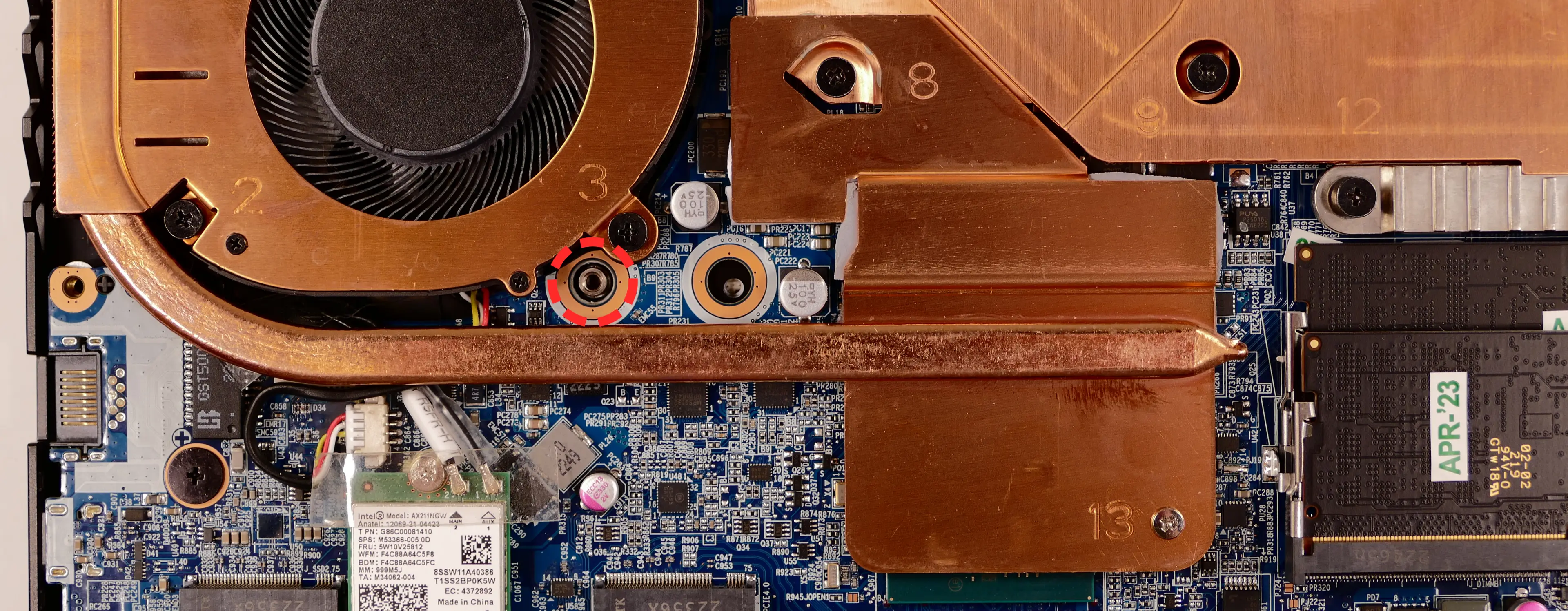

- Set the machine back down and raise the keyboard away from the chassis. The larger ribbon cable is for the keyboard, while the smaller ribbon cable is for the keyboard backlight.

- Flip the black latches upwards to free the ribbon cables.
- Pull the ribbon cables out of the connectors.
- Remove the keyboard and replace it with the new one.
- Carefully slide both ribbon cables into their connectors.
- Flip the black latches back into place to secure the ribbon cables.
- (Optional) Replace the keyboard adhesive strip on the chassis.
- Place the keyboard back into position, starting with the tabs on the bottom edge.
- Secure the rest of the keyboard by pressing down on each of its edges.
- Turn the machine lid-side down again.
- Replace the bottom panel.
Replacing the speakers:
The system has two bottom-firing speakers, which can be removed and replaced individually.
Tools required: Cross-head (Phillips) screwdriver
Time estimate: 10 minutes
Difficulty: Easy ●
Steps to replace the left speaker:
- Follow the steps above to remove the bottom cover and remove the main battery.
- Flip the black latches up to release both sides of the I/O daughterboard ribbon cable from the motherboard and the I/O daughterboard.
- The latches may be covered by clear tape; peel back or remove the tape.
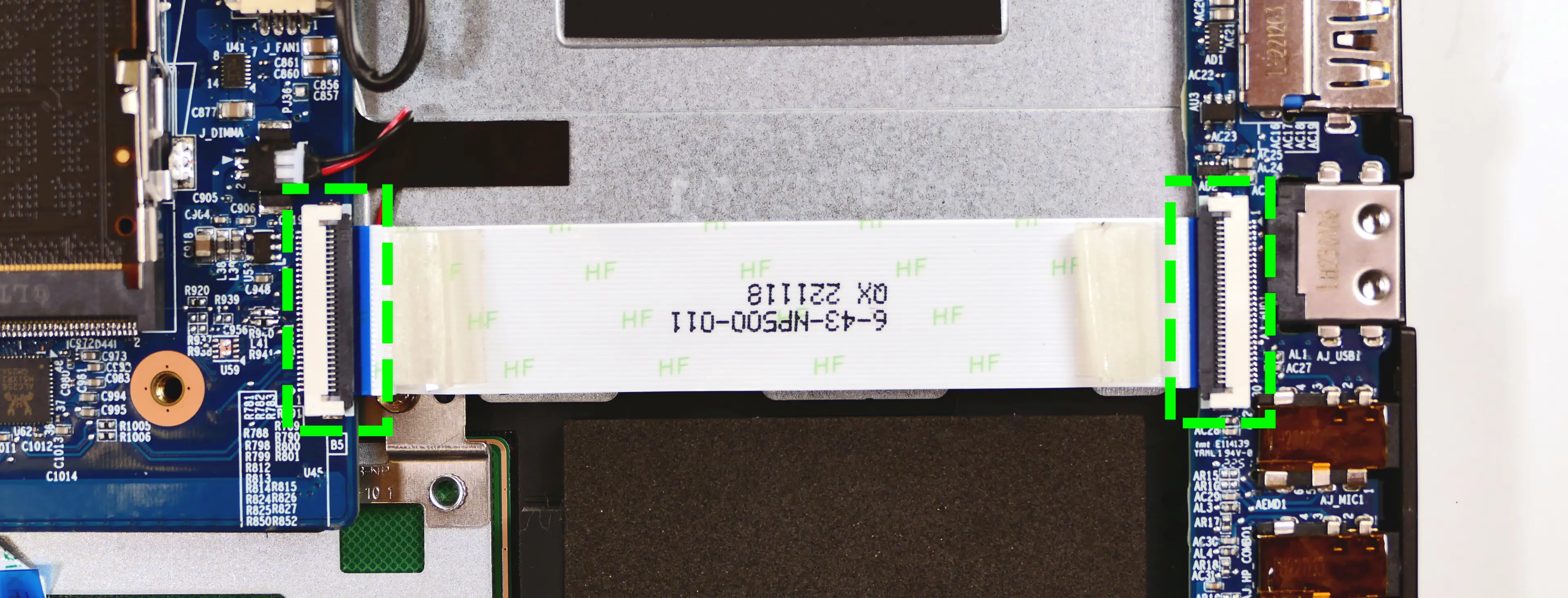
- Peel the ribbon cable away from the chassis.
- The ribbon cable is adhered to the chassis. Pull slowly to avoid damage.
- Disconnect the speaker connector from the motherboard.
- This can alternatively be done after freeing the speaker.

- Pull the speaker up and off of the plastic posts, and free the speaker wire from any tape and channels in the chassis.
- Slide the new speaker onto the plastic posts and connect it to the motherboard, securing the wire using the channels in the chassis.
- Reconnect the ribbon cable to the motherboard and I/O daughterboard, then flip the black latches to secure both connections.
- Replace the main battery and bottom cover.
Steps to replace the right speaker:
- Follow the steps above to remove the bottom cover.
- The outermost SSD can optionally be removed for easier access to the speaker connector.
- Disconnect the speaker connector from the motherboard.
- This can alternatively be done after freeing the speaker.

- Pull the speaker off of the plastic posts.
- Slide the new speaker onto the plastic posts and connect it to the motherboard.
- Replace the outermost SSD (if necessary) and bottom cover.
Adder WS (addw2)
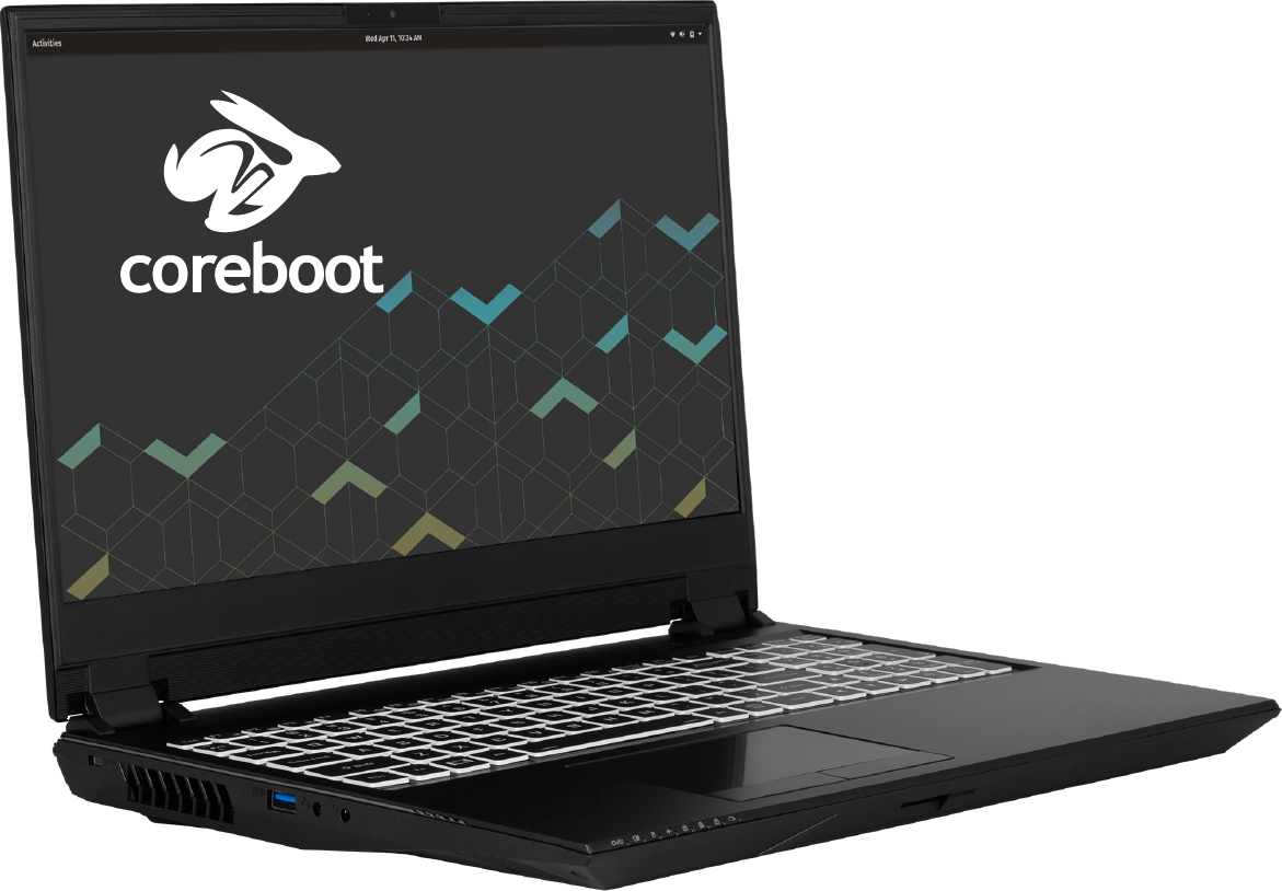
The System76 Adder WS is a laptop with the following specifications:
- CPU
- Supports Intel 10th Generation (Comet Lake) CPUs
- BIOS
- MX25L12872F flash chip
- SOIC-8 form factor
- Programmed with System76 Open Firmware or non-open firmware
- MX25L12872F flash chip
- EC
- ITE IT5570E
- Programmed with System76 EC or non-open EC firmware
- Graphics
- GPU: NVIDIA GeForce RTX 2070 Super
- eDP display: 15.6" 3840x2160@60Hz OLED
- OLED panel: Samsung ATNA56WR06 (or equivalent)
- External video outputs:
- 1x HDMI
- 1x Mini DisplayPort 1.4
- 1x DisplayPort 1.4 over USB-C
- Memory
- Up to 64GB (2x32GB) dual-channel DDR4 SO-DIMMs @ 3200 MHz
- Networking
- Gigabit Ethernet
- M.2 PCIe/CNVi WiFi/Bluetooth
- Intel Wi-Fi 6 AX200/AX201
- Power
- 230W (19.5V, 11.8A) DC-in port
- Barrel size: 5.5mm (outer), 2.5mm (inner)
- Included AC adapter: Chicony A17-230P1A
- AC power cord type: IEC C13
- 62Wh 6-cell Lithium-Ion battery
- Model number: PB50BAT-6
- 230W (19.5V, 11.8A) DC-in port
- Sound
- Internal speakers & microphone
- Combined headphone & microphone 3.5mm jack
- Combined microphone & S/PDIF (optical) 3.5mm jack
- HDMI, Mini DisplayPort, USB-C DisplayPort audio
- Storage
- M.2 (PCIe NVMe Gen 3 or SATA III) SSD-1
- M.2 (PCIe NVMe Gen 3) SSD-2
- 2.5" (7.0mm) SATA III
- SD card reader
- USB
- 1x USB Type-C with Thunderbolt 3
- 1x USB 3.2 Gen 2 Type-C
- DisplayPort 1.4 over USB-C
- 3x USB 3.0 (3.2 Gen 1) Type-A
- Dimensions
- 35.890cm x 25.806cm x 2.997cm, 2.5kg
Adder WS (External Overview)
Left side overview:

Right side overview:

Front side overview:

Back side overview:

Keyboard Shortcuts
The Adder WS has the following actions available using the Fn and Function keys:
| Key | Shortcut | Action |
|---|---|---|
 | Fn+F1 | Toggle trackpad |
 | Fn+F2 | Lock screen and toggle built-in LCD |
 | Fn+F3 | Mute |
 | Fn+F5 | Volume down |
 | Fn+F6 | Volume up |
 | Fn+F7 | Toggle displays |
 | Fn+F8 | Screen brightness down |
 | Fn+F9 | Screen brightness up |
 | Fn+F10 | Toggle webcam |
 | Fn+F11 | Toggle airplane mode |
 | Fn+F12 | Suspend |
| 1 | Fn+1 | Toggle fan between max/automatic |
 | Fn+* | Toggle keyboard backlight |
| / | Fn+/ | Cycle keyboard color |
| - | Fn+- | Decrease keyboard brightness |
| + | Fn++ | Increase keyboard brightness |
LED indicators

| Icon | Color | Description |
|---|---|---|
 | Orange | DC power plugged in |
| Green | Computer is on | |
| Blinking green | Computer is sleeping | |
 | Orange | Battery charging |
| Green | Battery fully charged | |
| Blinking orange | Battery critically low | |
 | Green | Airplane mode is on (WiFi/Bluetooth disabled) |
 | Green | Storage drive activity |
 | Green | Num Lock enabled |
 | Green | Caps Lock enabled |
 | Green | Scroll Lock enabled |
 | Off | GPU in MSHYBRD Mode |
| Green | GPU in Discrete Mode |
Adder WS (Internal Overview)
Bottom components and connectors:
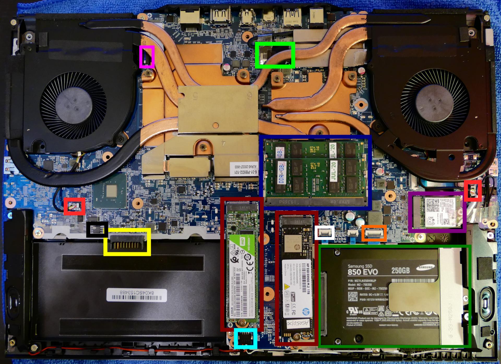
- RAM slots are highlighted in navy
- M.2 SSDs are highlighted in maroon
- 2.5" storage drive is highlighted in dark green
- Wireless card is highlighted in purple
- Fan connectors are highlighted in light red
- LCD panel connector is highlighted in light green
- Webcam/microphone connector is highlighted in pink
- Speaker connector is highlighted in cyan
- Touchpad connector is highlighted in white
- Front LED connector is highlighted in orange
- Battery connector is highlighted in yellow
- BIOS flash chip (U60) is highlighted in black
Under-keyboard components and connectors:
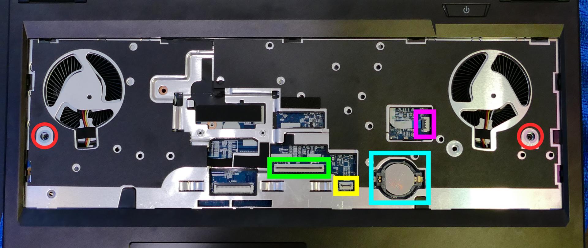
- Bottom panel screws are highlighted in red
- Keyboard connector is highlighted in green
- Keyboard backlight connector is highlighted in yellow
- CMOS battery is highlighted in cyan
- Power button/LED connector is highlighted in pink
Adder WS (Parts & Repairs)
Many components in your Adder WS can be upgraded or replaced as necessary. Follow these step-by-step guides for instructions:
- Removing the battery
- Removing the keyboard
- Removing the bottom cover
- Replacing the RAM
- Replacing an M.2/NVMe SSD
- Replacing a 2.5" storage drive
- Replacing the WiFi/Bluetooth module
- Replacing the CMOS battery
- Replacing the fans/heatsink/thermal paste
Removing the battery:
The battery provides primary power whenever the system is unplugged.
The model number for the Adder WS 2's battery is PB50BAT-6, and the original part number is 6-87-PB50S-61D02. Third-party battery sellers may list one or both of these numbers, and may offer other compatible part numbers with the same model number. You can also contact System76 to purchase a replacement battery.
Tools required: Cross-head (Phillips) screwdriver
Time estimate: 1 minute
Difficulty: Easy ●
Steps to remove the battery:
- Place the machine lid-side down.
- Use a soft surface (such as a towel) to avoid scratches.
- Remove the two battery screws, highlighted green below.
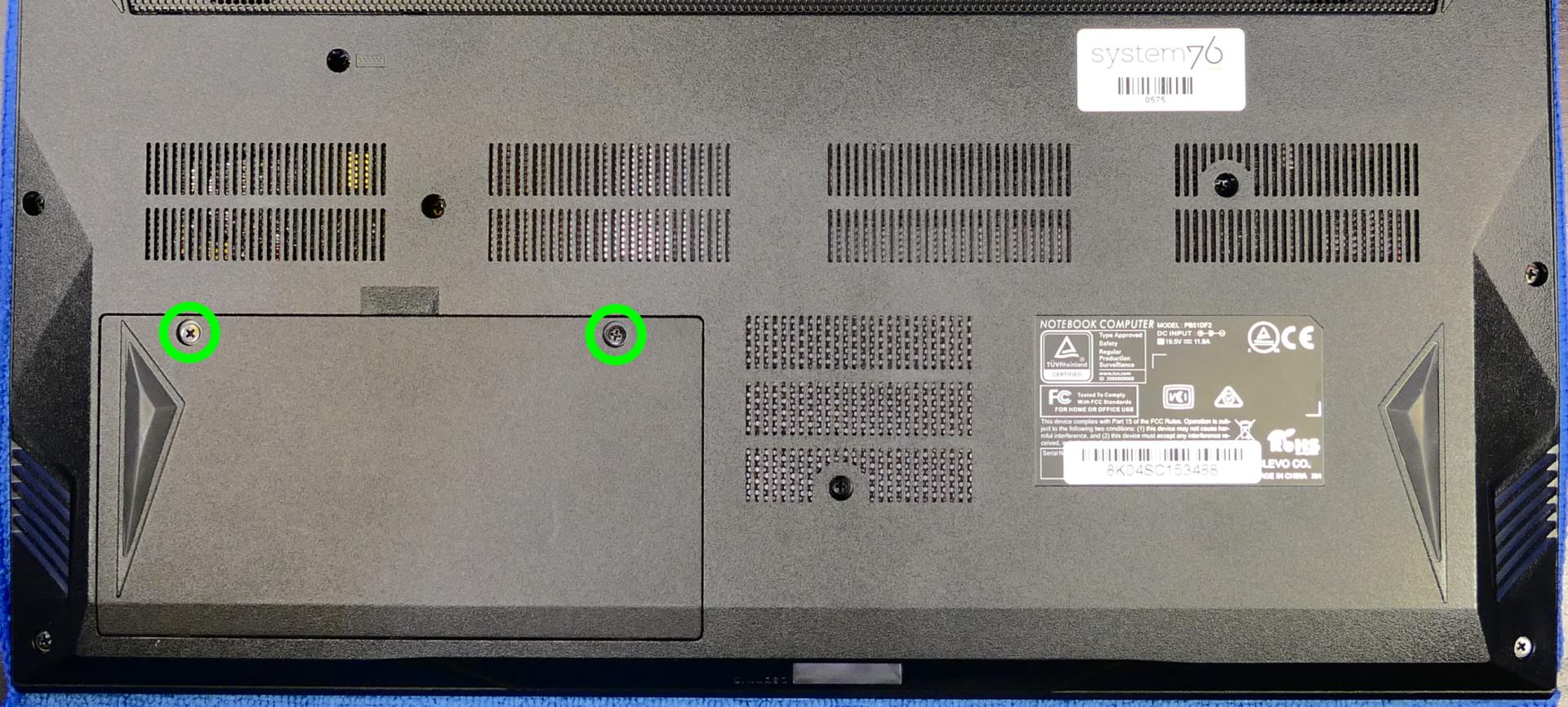
- Lift the battery out of the chassis.
Removing the keyboard:
The keyboard (and built-in keyboard backlight) can be replaced using the instructions below.
Tools required: Cross-head (Phillips) screwdriver
Time estimate: 5 minutes
Difficulty: Easy ●
Steps to remove the keyboard:
- Place the machine lid-side down.
- Use a soft surface (such as a towel) to avoid scratches.
- Remove the two keyboard screws.
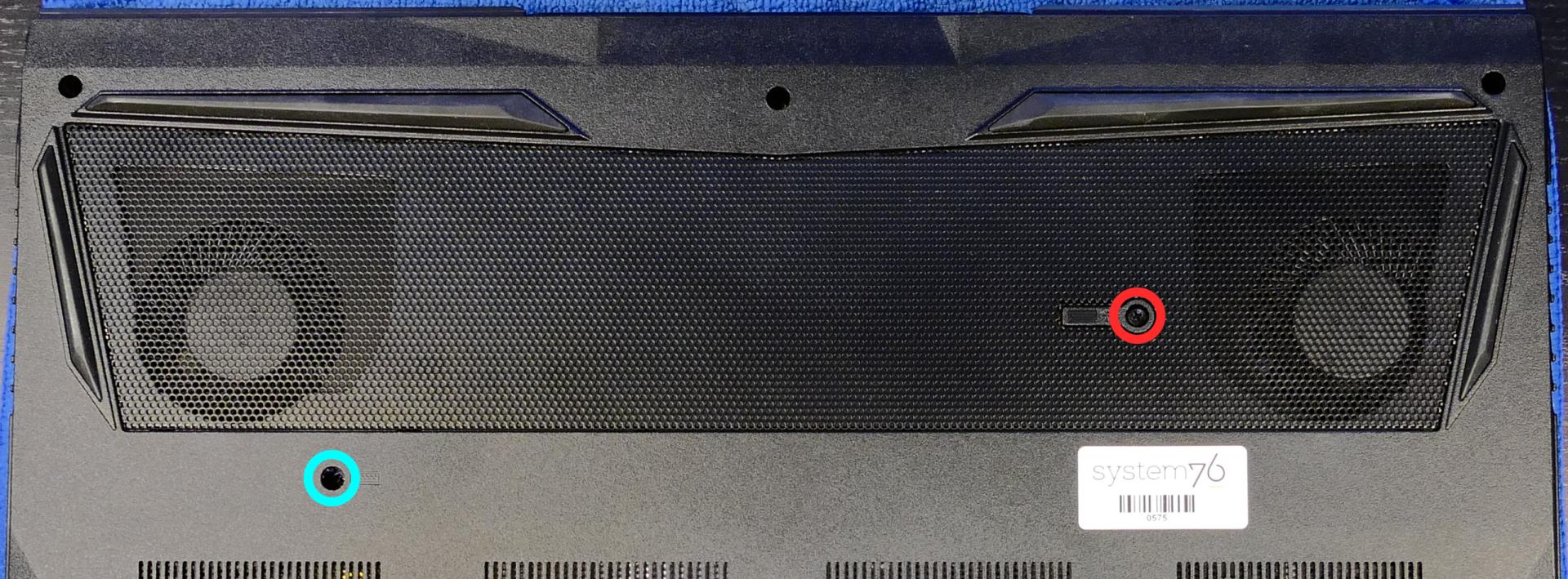
- Open the lid slightly and place the machine on its side.
- Push the screwdriver into the keyboard push point (highlighted red above) until the keyboard pops out.

- Set the machine upright and pull the keyboard out of the top case, starting from the top and working toward the bottom.
- Once freed, lift the bottom of the keyboard to see the ribbon cables. The larger ribbon cable is for the keyboard, while the smaller ribbon cable is for the keyboard backlight.
- If you are not replacing the keyboard, the keyboard can be flipped over onto the touchpad without disconnecting the ribbon cables.
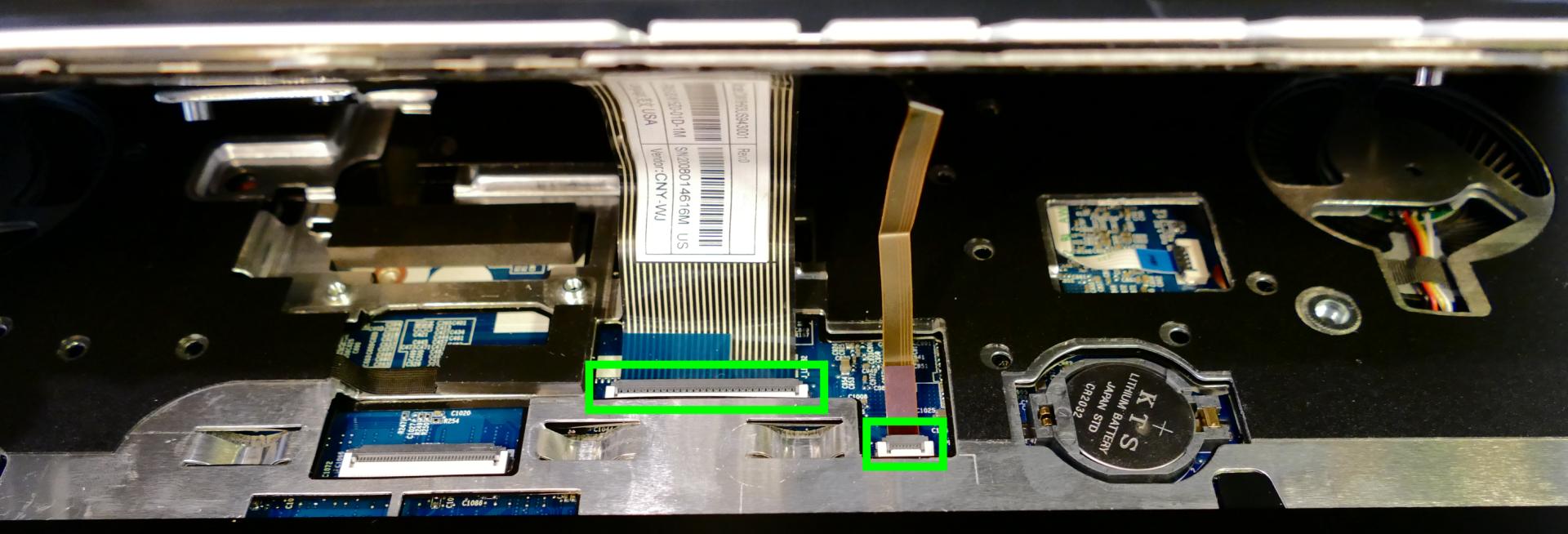
- Flip the black latches away from the white connectors to free the ribbon cables.
- Pull the ribbon cables out of the connectors.
- Remove the keyboard and replace it with the new one.
- Carefully slide both ribbon cables into their connectors.
- Flip the black latches back into place to secure the ribbon cables.
- Place the keyboard back into position, starting with the tabs on the bottom edge.
- Secure the rest of the keyboard by pressing down on each of its edges.
- Turn the machine lid-side down again and replace the two keyboard screws.
Removing the bottom cover:
Removing the cover is required to access most internal components. Prior to removing the cover, ensure the AC power is unplugged and all peripherals (including SD cards and USB drives) are unplugged or removed from the system.
Tools required: Cross-head (Phillips) screwdriver
Time estimate: 7 minutes
Difficulty: Easy ●
Steps to remove the bottom cover:
- Follow the steps above to remove the battery and remove the keyboard.
- Remove the two under-keyboard screws holding the bottom panel in place from the top.
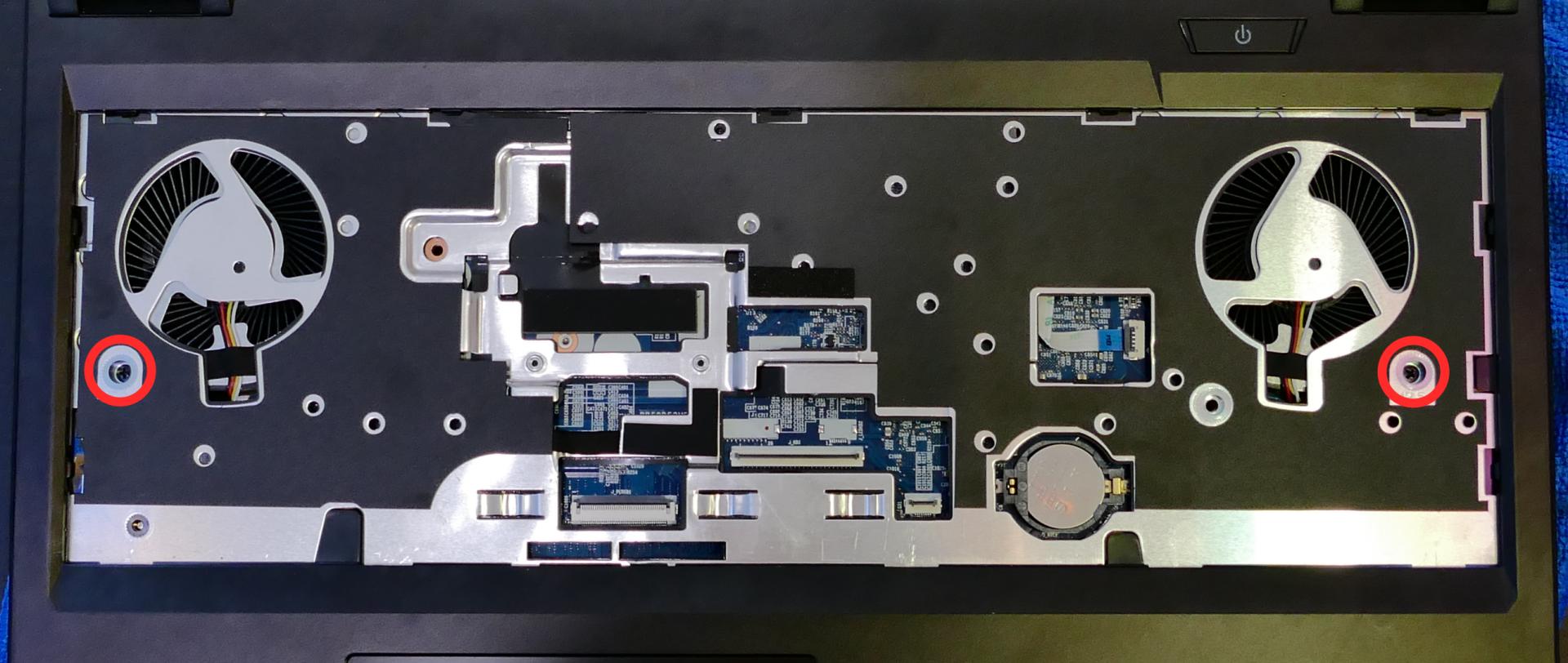
- Remove the remaining 10 bottom panel screws.
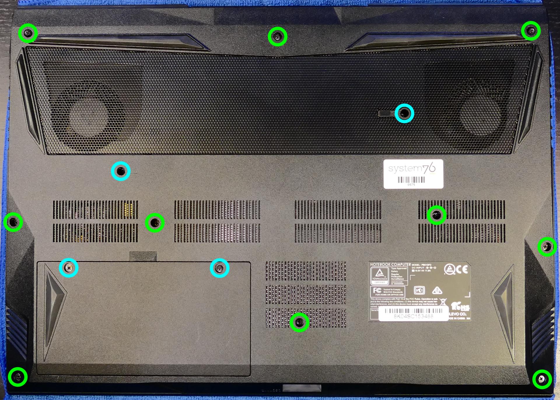
- Pull the bottom panel off, starting from the hinges and vents in the back.
Replacing the RAM:
The Adder WS 2 supports up to 64GB (2x32GB) of DDR4 SO-DIMMs running at 3200MHz. If you've purchased new RAM, need to replace your RAM, or are reseating your RAM, follow these steps.
Tools required: Cross-head (Phillips) screwdriver
Time estimate: 10 minutes
Difficulty: Easy ●
Steps to replace the RAM:
- Follow the steps above to remove the battery, remove the keyboard, and remove the bottom cover.
- Press the small tabs on both sides of the RAM simultaneously. The RAM should spring up to an angle.

- Remove the RAM from the slot.
- Insert the new RAM (or reseat the existing RAM) by placing it in the keyed slot and pressing down until it clicks into place.
Replacing an M.2/NVMe SSD:
This model supports two M.2 SSDs. Both slots are size 2280. SSD-1 supports PCIe NVMe Gen 3 or SATA III, while SSD-2 supports only PCIe NVMe Gen 3.
Tools required: Cross-head (Phillips) screwdriver
Time estimate: 10 minutes
Difficulty: Easy ●
Steps to replace the M.2 drive:
- Follow the steps above to remove the battery, remove the keyboard, and remove the bottom cover.
- Unscrew the retainer screw opposite the M.2 slot.
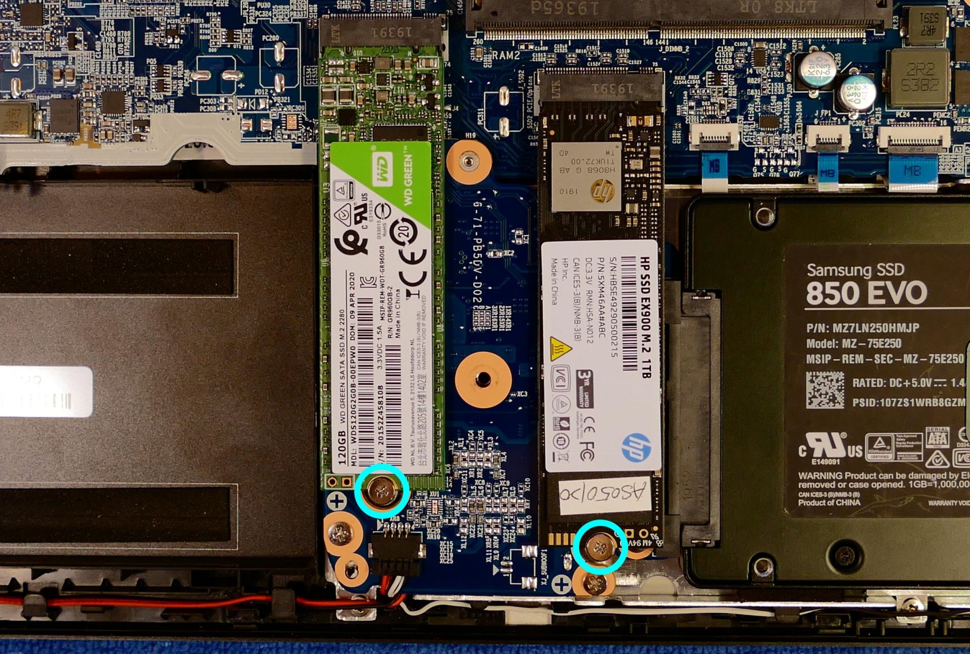
SSD-1 is on the left (closest to the battery slot), while SSD-2 is on the right (closest to the 2.5" drive slot.)
- Remove the existing M.2 drive by pulling it out of the slot.
- Insert the new M.2 drive into the slot and hold it in place.
- Replace the retainer screw.
Replacing a 2.5" storage drive:
This model supports one 2.5" (7mm height) SATA III SSD or hard drive.
Tools required: Cross-head (Phillips) screwdriver
Time estimate: 12 minutes
Difficulty: Easy ●
- Follow the steps above to remove the battery, remove the keyboard, and remove the bottom cover.
- Unscrew the single screw holding the 2.5" drive bracket into the case.
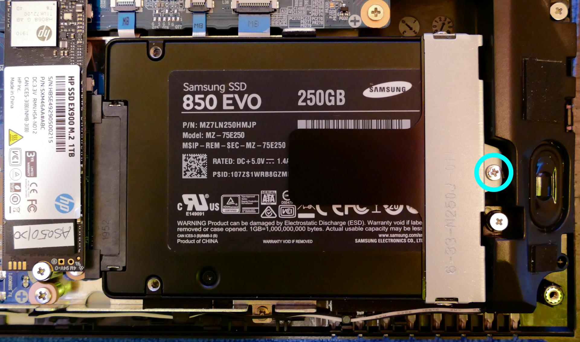
- Slightly lift the loose end of the 2.5" drive and slide it out of the SATA port.

- Unscrew the two screws holding the 2.5" drive into the drive bracket (one on either side.)

- Insert the new 2.5" drive into the drive bracket and replace the two side screws.
- Plug the 2.5" drive into the SATA port and set the drive into the case.
- Screw the drive bracket back into the case.
Replacing the wireless card:
Your Adder WS's WiFi and Bluetooth are both handled by the same module. It is a standard M.2 2230 slot with PCIe and USB interfaces (E-key).
Tools required: Cross-head (Phillips) screwdriver
Time estimate: 12 minutes
Difficulty: Medium ●
Steps to replace the WiFi/Bluetooth module:
- Follow the steps above to remove the battery, remove the keyboard, and remove the bottom cover.
- Locate the wireless module. Remove any clear tape that is securing the wires.
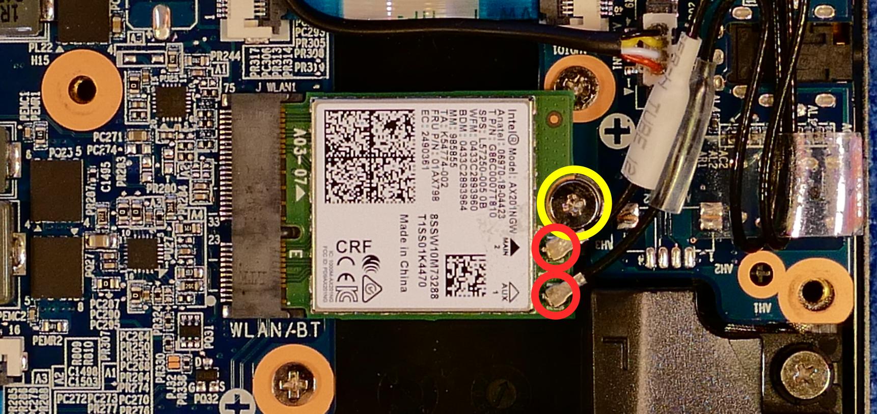
- Gently remove the two antennas (highlighted red above) by pulling them up and away from the wireless card.
- Remove the retaining screw opposite the M.2 slot, highlighted yellow above.
- The wireless card will pop up at an angle. Remove the card from the M.2 slot.
- Insert the new wireless card into the M.2 slot at an angle.
- Replace the retaining screw.
- Attach the two antennas by aligning the circular fittings and pressing onto the wireless card. The connectors will snap into place.
- Use caution when attaching the connectors; the pins can bend, break, or snap.
Replacing the CMOS battery:
The CMOS battery supplies power to the system's CMOS chip. UEFI settings and the computer's hardware clock are stored on the CMOS. If your system doesn't boot, you can reset the CMOS to force a low-level hardware reset. If your clock is constantly resetting, it's likely your CMOS battery needs to be replaced.
Warning (ingestion hazard): Keep batteries out of reach of children. Death or serious injury can occur if ingested. If a battery is suspected to be swallowed or inserted inside any part of the body, seek immediate medical attention. In the US, you can also call the National Battery Ingestion Hotline for guidance: 1 (800) 498-8666
Tools required: Cross-head (Phillips) screwdriver
Time estimate: 15 minutes
Difficulty: Medium ●
Steps to replace the CMOS battery:
- Follow the steps above to remove the keyboard.

- Pick the CMOS battery up from the open side of the battery slot (on the right).
- To clear the CMOS, remove the main battery, open the lid of the machine, and hold down the power button for at least 15 seconds to discharge any residual energy in the system.
- Replace the CMOS battery, keyboard, and main battery.
- Power up the machine. The system may power itself off and on after initial boot; this is normal behavior when the CMOS has been reset.
Replacing the cooling system:
The Adder WS 2 has a single heatsink with two attached fans. The entire cooling assembly should be replaced together (fans cannot be removed individually.)
If a fan becomes noisy and cleaning it out doesn't fix the issue, you may need a new fan. Contact Support to start a warranty claim or parts purchase.
Depending on your climate and the age of the machine, it may be necessary to apply new thermal paste between the CPU/GPU and the heatsink. Thermal paste helps facilitate effective heat transfer between the CPU/GPU and the cooling equipment. These instructions can also be used in the unlikely event your heatsink needs replacing.
Tools required: Cross-head (Phillips) screwdriver, thermal paste
Time estimate: 20 minutes
Difficulty: High ●
Steps to replace the fans/heatsink/thermal paste:
- Follow the steps above to remove the battery, remove the keyboard, and remove the bottom cover.
- Unplug the two white fan connectors, highlighted red below.
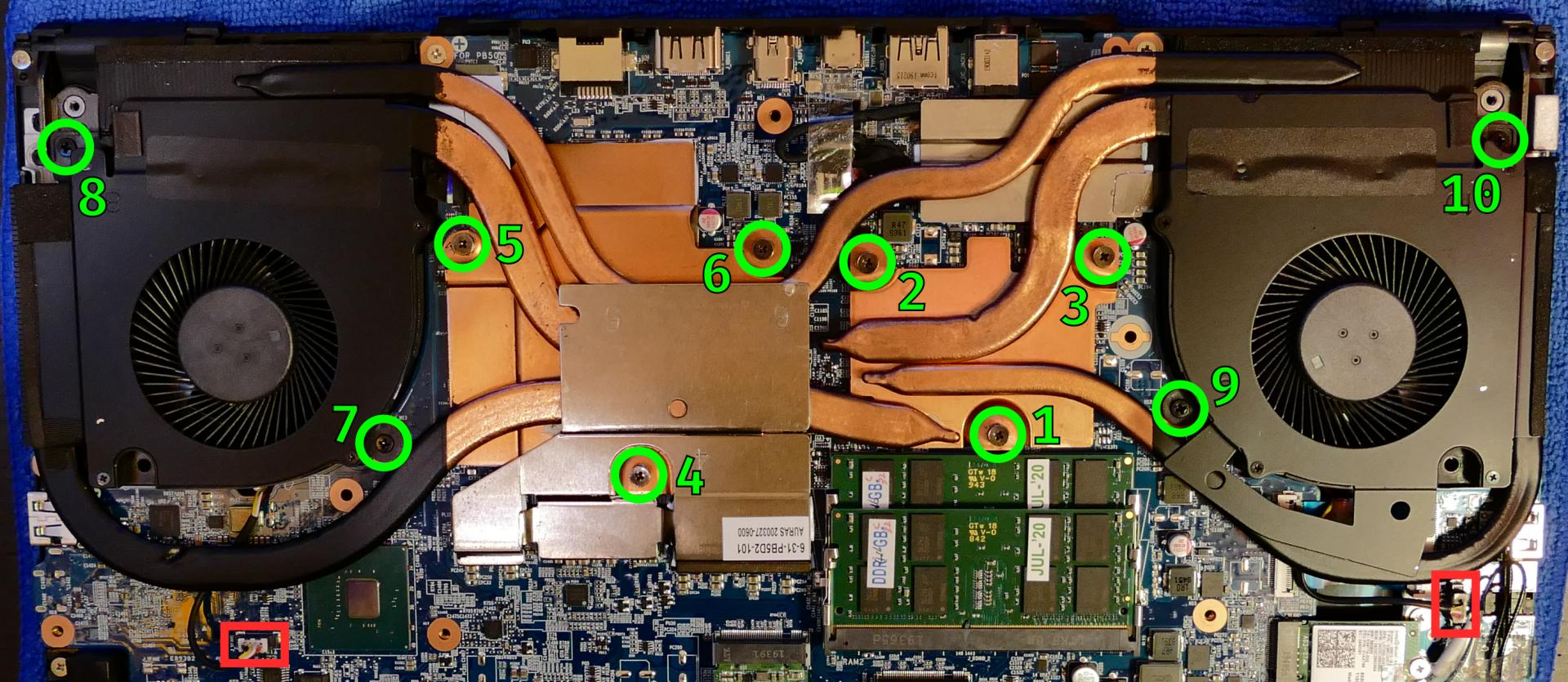
- Remove the six heatsink screws and four fan screws in order, starting with #1, then #2, and so on until #10.
- The heatsink screws are spring-loaded, and will not detatch from the heatsink when unscrewed.
- Remove the heatsink from the system, being careful not to bend the heatsink pipes. It may take some pressure to break the seal of the thermal paste.
- Using a paper towel, remove the existing thermal paste. You may also use a small amount of rubbing alcohol if the old paste is dried or difficult to remove.

- After cleaning the CPU, GPU, and heatsink, apply a small line of thermal paste directly onto the CPU/GPU chips.
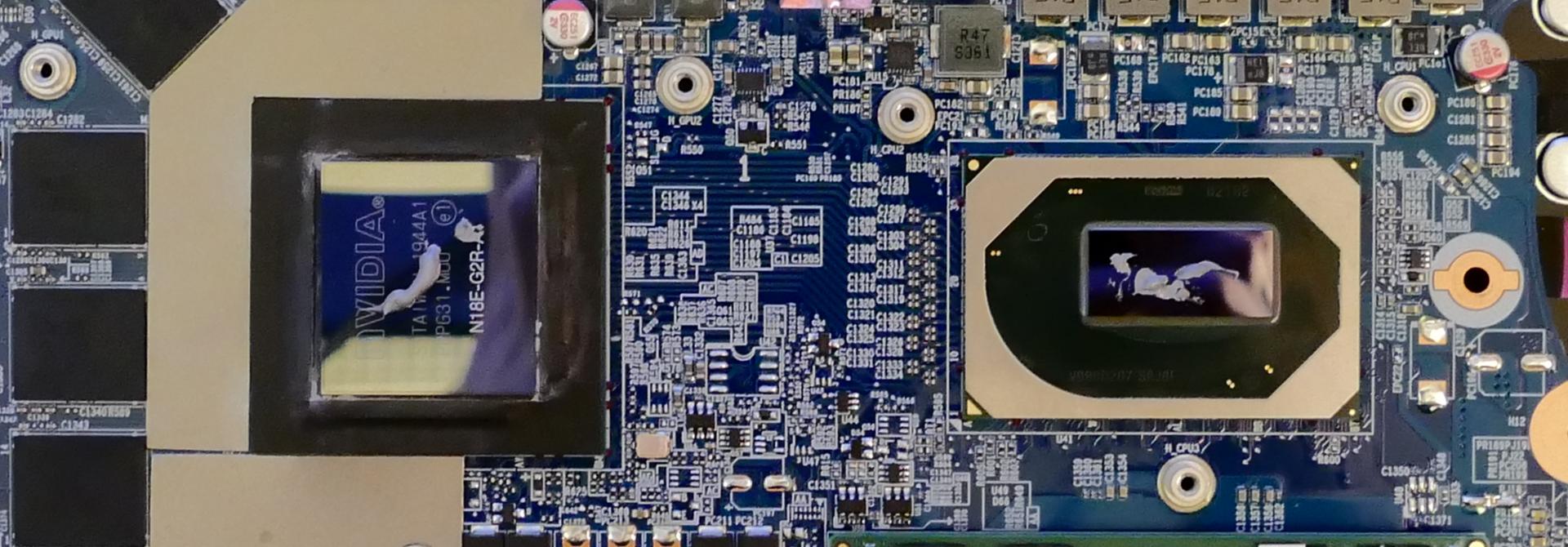
- Carefully replace the heatsink.
- Replace the six heatsink screws and four fan screws in order, starting with #1, then #2, and so on until #10.
- Plug in the two white fan connectors.
Adder WS (addw1)
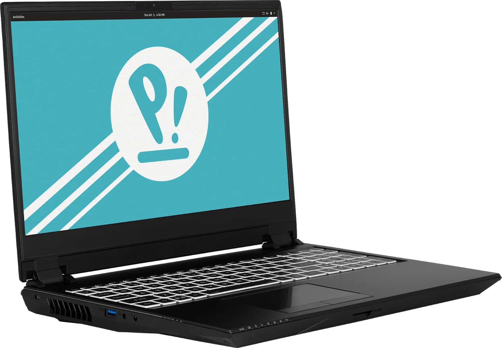
The System76 Adder WS is a laptop with the following specifications:
- CPU
- Supports Intel Coffee Lake-H CPUs
- BIOS
- MX25L12873F flash chip
- SOIC-8 form factor
- Programmed with System76 firmware (non-open)
- MX25L12873F flash chip
- EC
- ITE IT8587E
- Programmed with non-open EC firmware
- Graphics
- GPU: NVIDIA GeForce RTX 2070
- eDP display: 15.6" 3840x2160@60Hz OLED
- OLED panel: Samsung ATNA56WR06 (or equivalent)
- External video output:
- 1x HDMI (w/HDCP)
- 1x Mini DisplayPort 1.3
- 1x DisplayPort 1.3 over USB 3.1 Type C
- Memory
- Up to 64GB dual-channel DDR4 @ 2666 MHz, or
- Up to 32GB dual-channel DDR4 @ 3000 MHz
- Power
- 230W (19.5V, 11.8A) DC-in port
- Barrel size: 5.5mm (outer), 2.5mm (inner)
- Included AC adapter: Chicony A17-230P1A
- AC power cord type: IEC C13
- 62Wh 6-cell Lithium-Ion battery
- Model number PB50BAT-6
- 230W (19.5V, 11.8A) DC-in port
Adder WS (External Overview)
Left side overview:

Right side overview:

Front side overview:
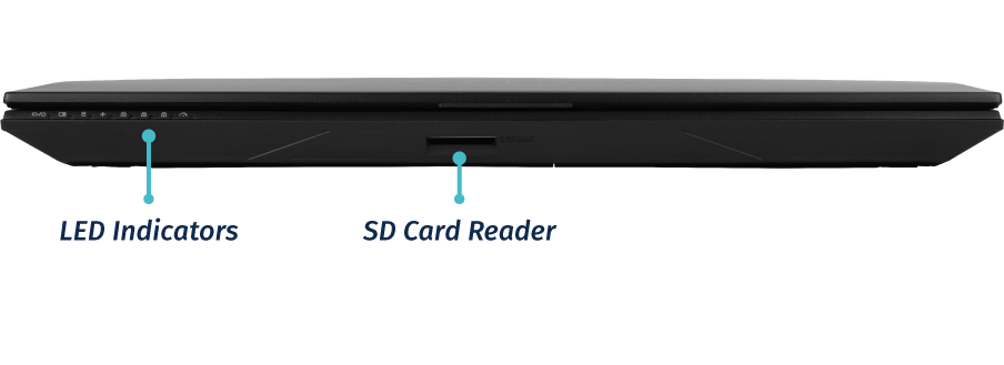
Back side overview:

Bottom case screw sizes
The Adder WS uses a single size of screw for securing the bottom case, battery, and keyboard.
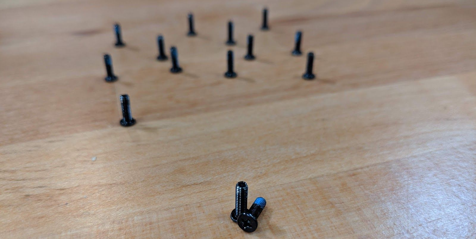
Front LED lights

| Icon | Color | Description |
|---|---|---|
 | Orange | DC power plugged in |
| Green | Computer is on | |
| Blinking green | Computer is sleeping | |
 | Orange | Battery charging |
| Green | Battery fully charged | |
| Blinking orange | Battery critically low | |
 | Green | Airplane mode is on (WiFi/Bluetooth disabled) |
 | Green | Storage drive activity |
 | Green | Num Lock enabled |
 | Green | Caps Lock enabled |
 | Green | Scroll Lock enabled |
 | Off | GPU in MSHYBRD Mode |
| Green | GPU in Discrete Mode |
Keyboard Shortcuts
The Adder WS has the following actions available using the Fn and Function keys:
| Key | Shortcut | Action |
|---|---|---|
 | Fn+F1 | Toggle trackpad |
 | Fn+F2 | Lock screen and toggle built-in LCD |
 | Fn+F3 | Mute |
 | Fn+F5 | Volume down |
 | Fn+F6 | Volume up |
 | Fn+F7 | Toggle displays |
 | Fn+F8 | Screen brightness down |
 | Fn+F9 | Screen brightness up |
 | Fn+F10 | Toggle webcam |
 | Fn+F11 | Toggle airplane mode |
 | Fn+F12 | Suspend |
| 1 | Fn+1 | Toggle fan between max/automatic |
 | Fn+* | Toggle keyboard backlight |
| / | Fn+/ | Cycle keyboard color |
| - | Fn+- | Decrease keyboard brightness |
| + | Fn++ | Increase keyboard brightness |
External Displays
The Adder WS supports Mini DisplayPort, HDMI, and DisplayPort over USB-C connections for external displays.
Adder WS (Internal Overview)
Bottom panel overview:
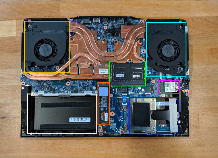
- GPU fan is highlighted in cyan
- GPU fan is highlighted in light orange
- RAM is highlighted in green
- M.2 SSD is highlighted in orange
- Wireless/Bluetooth module is highlighted in purple
- Battery is highlighted in white
- 2.5" drive bay is highlighted in blue
- BIOS flash chip (U61), not highlighted
Under-the-keyboard overview:
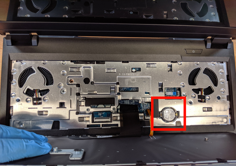
- CMOS battery is highlighted in red
Adder WS (Parts & Repairs)
Many components on your Adder WS can be upgraded or replaced as necessary. Follow these step-by-step guides for instructions:
- Replacing the keyboard
- Removing the bottom cover
- Replacing the RAM
- Replacing an M.2/NVMe SSD
- Replacing a 2.5" storage drive
- Replacing the fans/heatsink/thermal paste
- Replacing the CMOS battery
- Replacing the external battery
- Replacing the WiFi/Bluetooth module
Replacing the keyboard:
Keyboard replacement is simple and requires only a cross-head screwdriver.
Tools required: Cross-head (Phillips) screwdriver
Time estimate: 10 minutes
Difficulty: Easy ●
Screws: 2 total - 2 x M2 (black)
Steps to replace the keyboard:
- Place the machine lid-side down.
- Use a soft surface (such as a towel) to avoid scratches.
- Remove the 2 keyboard screws, indicated by the small keyboard icons.
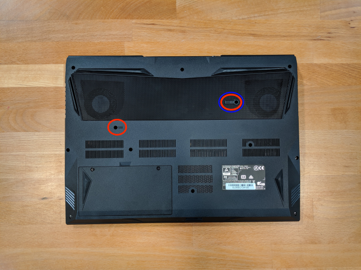
- Open the Adder WS and place it on its side.
- Push the screwdriver into the keyboard push point until the keyboard pops out.
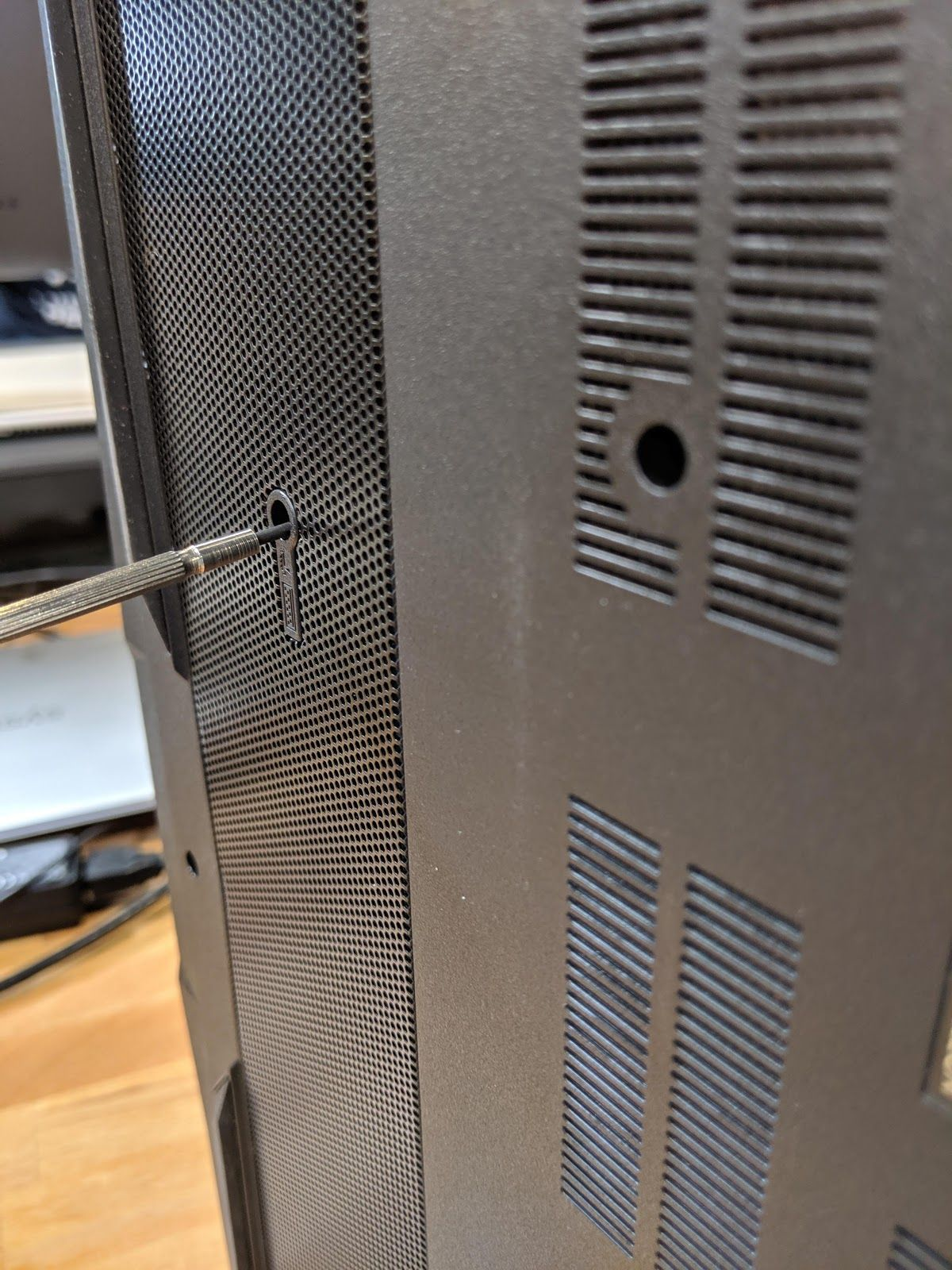
- Set the Adder WS down, then starting from the top side, pull the keyboard loose.
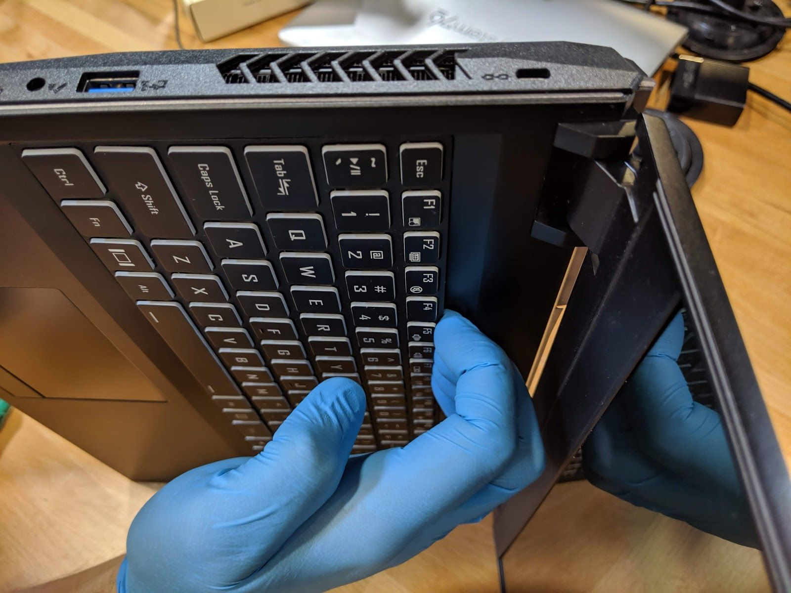
- Flip the keyboard over onto the trackpad.
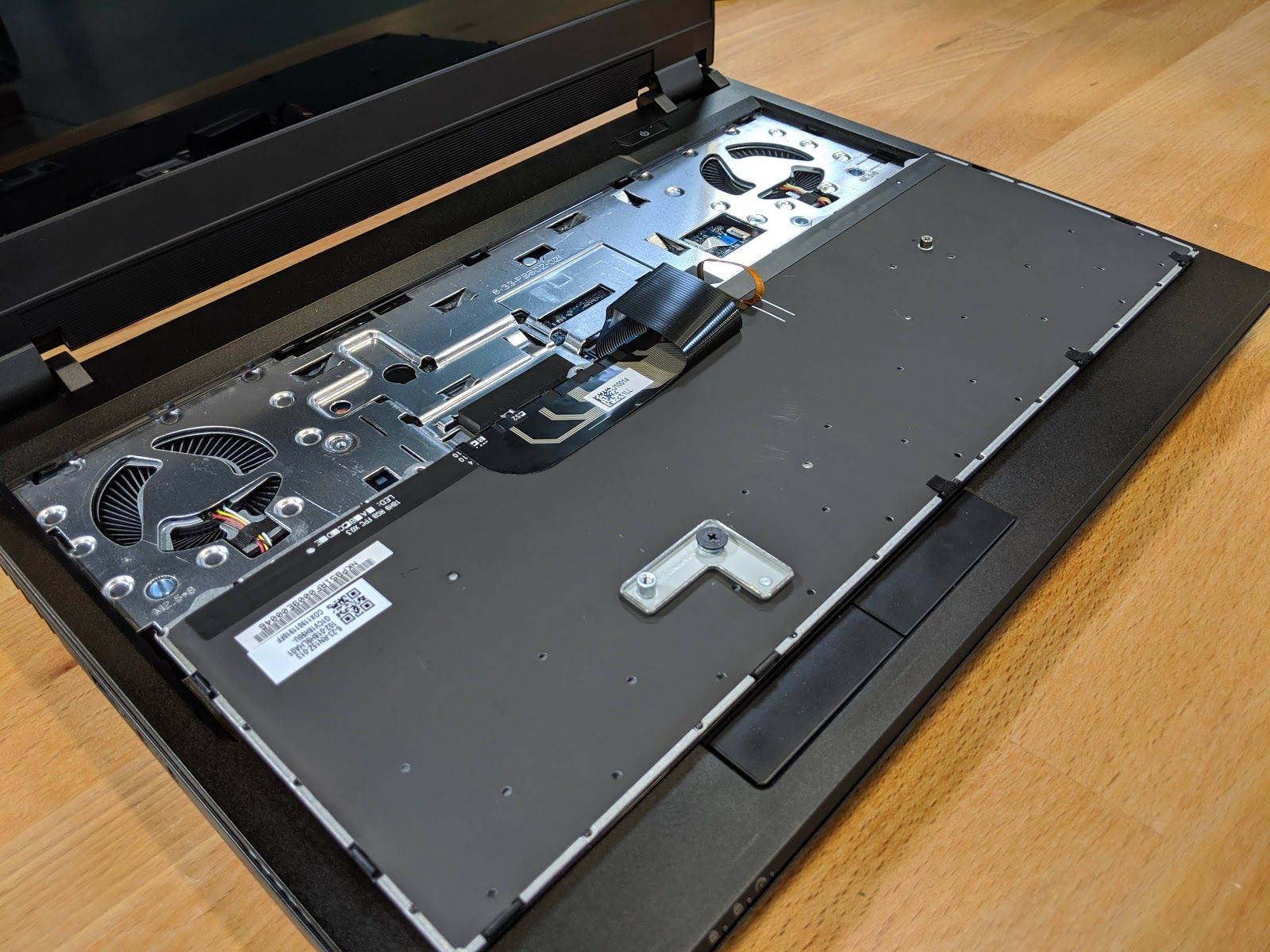
- Pull the large ribbon cable out of the connector.
- The small ribbon cables have latches. Gently pull the latches from both sides and remove the ribbon cables.
- Remove the keyboard and replace it with the new one.
- Insert the large ribbon cable into the connector.
- Seat the small ribbon cables, then apply pressure equally to both sides of the connector to secure.
- Flip the keyboard over and press the bottom tabs of the keyboard into the case.
- Secure the keyboard by pressing down on the edges of the keyboard.
- Flip the Adder WS over.
- Replace the 2 screws holding the keyboard in place.
- Boot your Adder WS and confirm the keyboard is operational.
Removing the bottom cover:
Removing the cover is required to access the internal components. Prior to removing the cover, ensure the AC power is unplugged and all peripherals (including SD cards and USB drives) are unplugged or removed from the system.
Tools required: Cross-head (Phillips) screwdriver
Time estimate: 10 minutes
Difficulty: Medium ●
Screws: 14 total - 12 x M2 perimeter (black); 2 x M2 keyboard (black)
Steps to remove the bottom cover:
- Place the machine lid-side down.
- Use a soft surface (such as a towel) to avoid scratches.
- Remove the external battery.
- Remove the keyboard.
- Remove the two screws underneath the keyboard labeled ‘M2’.
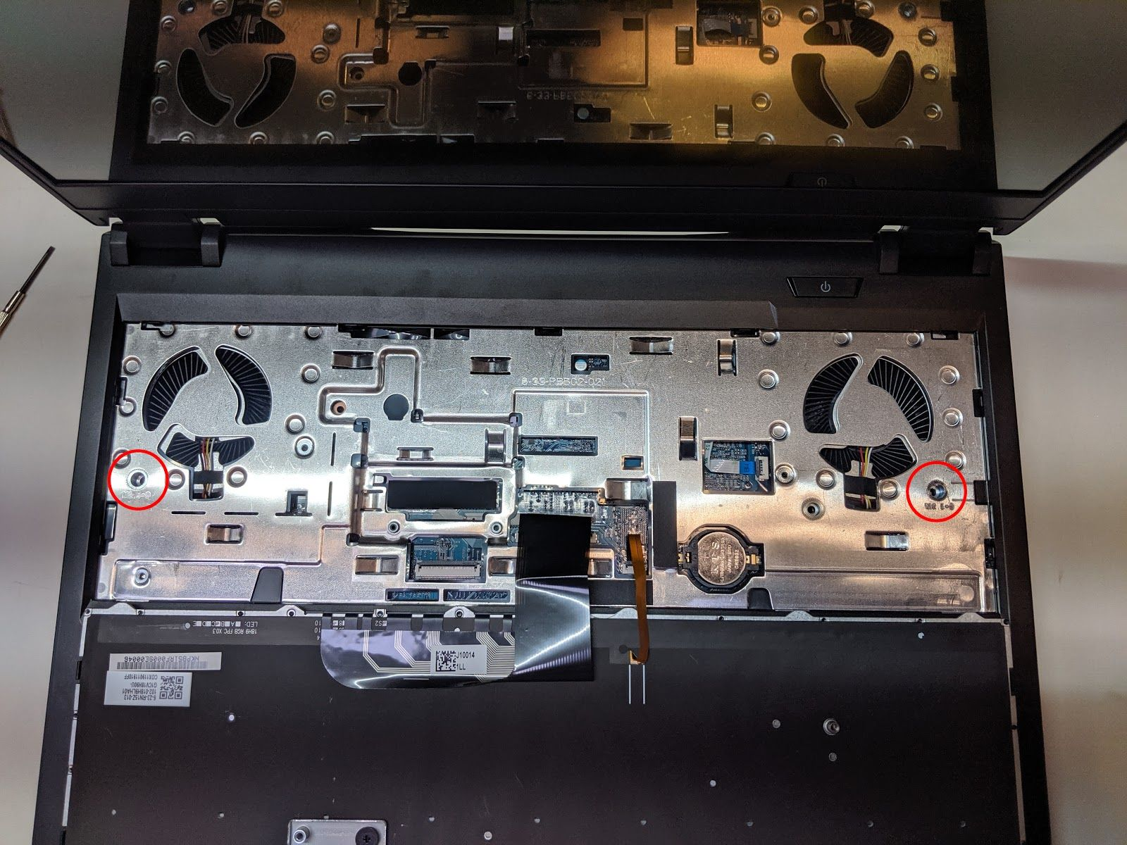
- Remove the 12 perimeter screws.
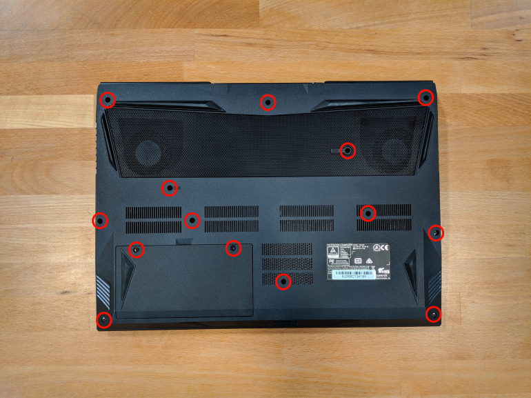
- The bottom cover will lift off, starting from the front corners working to the back near the hinges.
Steps to replace the bottom cover:
- Align the bottom cover to the case towards the back and hinges.
- Set the bottom cover along the edges and confirm the bottom cover is seated.
- Replace the 12 perimeter screws.
- Replace the 2 keyboard screws.
Replacing the RAM:
RAM acts as temporary storage for your computer. More RAM generally provides better performance. If you've purchased new RAM, need to replace your RAM, or are reseating your RAM, follow these steps.
Tools required: Cross-head (Phillips) screwdriver
Time estimate: 15 minutes
Difficulty: Medium ●
Steps to replace the RAM:
- Follow the steps above to remove the bottom cover.
- Press the small tabs on both sides of the RAM simultaneously. The RAM should spring up to an angle.
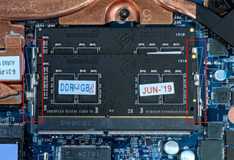
- Remove the RAM from the slot.
- Insert the new RAM (or reseat the existing RAM) by placing it in the keyed slot and pressing down on the RAM until it clicks into place.
Replacing an M.2/NVMe SSD:
M.2 SSDs offer, at minimum, SATA III speeds and performance in a package about the size of a stick of gum. NVMe M.2 SSDs offer even higher performance. The Adder WS supports two M.2 SSDs, size 2280, either M.2 SATA or NVMe M.2 PCIe Generation 3.
Tools required: Cross-head (Phillips) screwdriver
Time estimate: 5 minutes
Difficulty: Medium ●
Steps to replace the M.2 drive:
- Follow the steps above to remove the bottom cover.
- Locate the M.2 drive (or slot.)
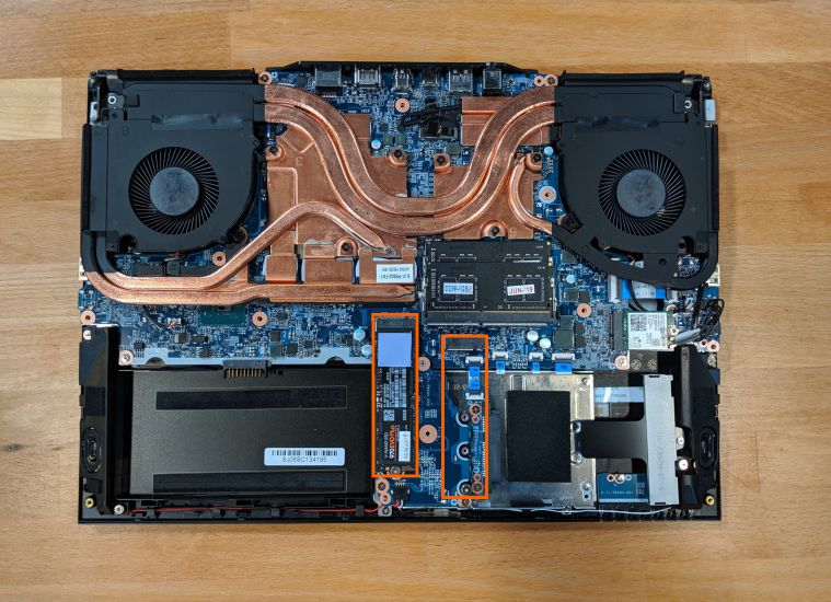
- Unscrew the retainer screw opposite the M.2 slot.
- Remove the existing M.2 drive by pulling it out of the slot.
- Insert the new M.2 drive into the slot and hold it in place.
- Replace the retainer screw.
Replacing a 2.5" storage drive:
This model supports one 2.5" (7mm height) SATA III SSD or hard drive.
Tools required: Cross-head (Phillips) screwdriver
Time estimate: 12 minutes
Difficulty: Easy ●
- Follow the steps to remove the battery, remove the keyboard, and remove the bottom cover.
- Unscrew the single screw holding the 2.5" drive bracket into the case.

- Slightly lift the loose end of the 2.5" drive and slide it out of the SATA port.

- Unscrew the two screws holding the 2.5" drive into the drive bracket (one on either side.)

- Insert the new 2.5" drive into the drive bracket and replace the two side screws.
- Plug the 2.5" drive into the SATA port and set the drive into the case.
- Screw the drive bracket back into the case.
Replacing the cooling system:
If the CPU fan becomes noisy and cleaning it out doesn't fix the issue, you may need a new CPU fan. Contact Support to start a warranty claim or parts purchase.
In rare cases, or after several years, it may be necessary to apply new thermal paste between the CPU and the heatsink. Thermal paste helps facilitate effective heat transfer between the CPU and the cooling equipment. These instructions can also be used in the unlikely event your heatsink needs replacing.
Tools required: Cross-head (Phillips) screwdriver
Time estimate: 5 minutes
Difficulty: High ●
Steps to replace the fans/heatsink/thermal paste:
- Follow the steps above to remove the bottom cover.
- Locate the CPU heatsink screws.
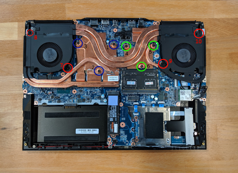
- Remove the screws, starting with #10, then #9, and continue until you have removed #1.
- Carefully remove the heatsink/fans from the case.
- Using a paper towel, remove the existing thermal paste. You may also use a small amount of rubbing alcohol to remove excess or difficult-to-remove paste.
- After cleaning the CPU, GPU, and heatsink, apply a small line of thermal paste directly onto the CPU and GPU core.
- Carefully replace the heatsink.
- Replace the screws, starting with #1, then #2, and so on until #10. Do not fully tighten until sets #1-#3 and #4-#6 are in place, then fully tighten all screws for each set (#1-#3 and #4-#6).
Replacing the CMOS battery:
The CMOS battery supplies power to the Adder WS's CMOS chip. Changes you make to the BIOS and the computer's hardware clock are stored on the CMOS. If your Adder WS doesn't boot, you can reset the CMOS to force a low-level hardware reset. If your clock is constantly resetting, it's likely your CMOS battery needs replacing.
Warning (ingestion hazard): Keep batteries out of reach of children. Death or serious injury can occur if ingested. If a battery is suspected to be swallowed or inserted inside any part of the body, seek immediate medical attention. In the US, you can also call the National Battery Ingestion Hotline for guidance: 1 (800) 498-8666
Tools required: Cross-head (Phillips) screwdriver
Time estimate: 5 minutes
Difficulty: Medium ●
Steps to replace the CMOS battery:
- Follow the steps above to remove the keyboard.
- Locate the CMOS battery. Use a thin plastic tool to remove the CMOS battery.
- Power up the Adder WS. The system may power itself off and on after initial boot; this is normal behavior.
- Press F2 to enter the BIOS.
- Choose the "Setup Utility".
- Press F9 to Load Setup Defaults.
- Click on "Advanced" in the left menu.
- Choose "Advanced Chipset Control".
- Choose "ME State" and set this option to "Disabled".
- Press F10 to save and resume normal boot.
Replacing the external battery
The battery provides primary power whenever the system is unplugged.
The model number for the Adder WS 1's battery is PB50BAT-6. You can contact System76 to purchase a replacement battery.
Tools required: Cross-head (Phillips) screwdriver
Time estimate: 5 minutes
Difficulty: Easy ●
Steps to replace the external battery
- Place the machine lid-side down.
- Use a soft surface (such as a towel) to avoid scratches.
- Remove the two screws that hold the battery and then remove the battery.
- Place the new battery in and then add the two screws back.
Replacing the wireless card
Your Adder WS's WiFi and Bluetooth are both handled by the same module. It is a standard M.2 2230 slot with PCIe and USB interfaces (E-key).
Tools required: Cross-head (Phillips) screwdriver
Time estimate: 5 minutes
Difficulty: Medium ●
Steps to replace the WiFi/Bluetooth module
- Follow the steps above to remove the bottom cover.
- Locate the wireless card.
- Gently remove the two antennas by pulling them up and away from the wireless card.
- Remove the retaining screw opposite the M.2 slot.
- Remove the wireless card from the M.2 slot.
- Insert the new wireless card into the M.2 slot.
- Replace the retaining screw.
- Attach the two antennas by aligning the circular fitting and pressing onto the wireless card. The connector will snap into place. Use caution when attaching the connectors; the pins can bend, break, or snap.
Adder WS (UEFI Setup & Specifications)
When starting your Adder WS, it takes a few seconds to conduct a quick check of the components. As it proceeds, it will notify you if anything is wrong. Any issues that prevent the system from booting will be displayed and you will be prompted to enter the Setup. If no problems are detected, your Adder WS will load GRUB for Ubuntu or systemd-boot for Pop!_OS.
- For Setup/BIOS, hold F2 while booting.
- For boot options, hold F7 while booting and choose your preferred boot device.
Updating the BIOS
BIOS/UEFI firmware updates and instructions are sent out as needed. The firmware manager will notify you if a firmware update is available for your Adder WS. You can also check for updates under Settings -> Devices -> Firmware in Pop!_OS, or using the Firmware Manager app in Ubuntu.
BIOS overview
The BIOS/UEFI Setup utility allows you to make low-level changes to your Adder WS. It's not recommended to make changes unless the settings are provided by Support or you understand what you're changing.
Setup Utility
-
SATA Port #: Opens the sub-menu to show the configuration of a SATA device on the SATA ports.
-
OffBoard SATA/NVMe Controller Configuration: Opens the sub-menu to show the configuration of any devices on the offboard SATA/NVMe controller, if installed.
-
System Date/Time: Sets the system date/time using the hardware clock.
-
System/Extended Memory: Displays information about the amount of RAM installed.
-
ME FW/MB Series/BIOS Version/KB/EC Firmware Rev: Displays information about the BIOS version(s).
-
MAC Address: Displays the network adapter's hardware address.
Advanced
-
Advanced Chipset Control: Options for FlexiCharger, GPU Performance Scaling, Intel Speed Shift Technology, VT-d, UEFI OS Fast Boot, Software Guard Extensions (SGX), ME State, HeadPhone PC Beep Sound Support.
-
FlexiCharger: Options to enable/disable FlexiCharger. FlexiCharger will not start charging the battery unless it is below the lower threshold, and will stop charging the battery at the upper threshold. Using FlexiCharger for extended periods of time will decrease the battery indicator's accuracy.
-
GPU Performance Scaling: NVIDIA GPU Performance Scaling Support. Disabling this may cause issues with booting.
-
Intel Speed Shift Technology: Enabling will expose the CPPCv2 interface to allow for hardware controlled P-states (power states.)
-
VT-d: Enable/disable Intel Virtualization Technology for Directed I/O. Extends Intel Virtualization Technology (VT) by providing hardware assets for virtual hypervisors.
-
UEFI OS Fast Boot: When enabled, the system firmware does not initialize the keyboard or check for the firmware menu key.
-
Software Guard Extensions (SGX): Enable or disable Intel SGX (Software Guard Extensions.)
-
ME State: Intel Management Engine. Recommended to Disable.
-
Headphone PC Beep Sound Support: If disabled, there will be no alarm beep sound at boot time though the headphones.
-
-
Thunderbolt(TM) Configuration:
-
Discrete Thunderbolt(TM) Support: Enable or disable Thunderbolt(TM) Support.
-
Security Level: Security level selection for Thunderbolt(TM).
-
-
OverClocking Performance Menu: Memory overclocking options.
- Memory: Select the DIMM timing profile. For 3000MHz memory, use the XMP1 profile.
-
SATA Mode: The SATA (Seral ATA) controller is designed to operate in AHCI (Advanced Host Controller Interface) mode only.
-
Power on boot beep: Enable/disable a beep as the computer starts up.
-
Battery low alarm beep: Enable/disable a beep when the battery is critically low.
Security
-
Set Supervisor Password: Sets a password for the Setup Utility. This does not affect access to the computer or installed OS, only the BIOS/UEFI.
-
TPM Configuration: Trusted Computing settings.
- Security Device Support: Enables or disables BIOS support for the TPM 2.0 security device.
Administer Secure Boot
- Secure Boot: Enables support for Secure Boot. This is not recommended or required for Ubuntu/Pop!_OS.
Boot
-
EFI: Sets the boot order and chooses which boot devices are enabled.
-
UEFI Setting: Contains other settings regarding boot devices.
-
Network Stack: Enables or disables support for Intel PXE network boot.
-
IPv4 PXE Support: Allow PXE booting using IPv4.
-
IPv6 PXE Support: Allow PXE booting using IPv6.
-
Specifications
-
Processors:
-
Intel® CoreTM i7-9750H (4.1GHz): 2.6 up to 4.50GHz - 12MB Cache – 6 Cores – 12 Threads
-
Intel® CoreTM i9-9980HK (4.1GHz): 2.4 up to 5.0GHz - 16MB Cache – 8 Cores – 12 Threads
-
-
Display: 15.6” 4K (3840x2160) OLED Glossy
-
Memory:
- Dual Channel DDR4
- Two 260-pin SO-DIMM sockets
- Supports DDR4 2666MHz memory modules (real operational frequency depends on the FSB of the processor.)
- Memory expandable up to 64GB (compatible with 8GB/16GB/32GB modules.)
-
Graphics: NVIDIA GeForce RTX 2070
-
Storage:
- Two M.2 SSD 2280 slots, supporting SATA and PCIe Gen3x4
- One 2.5" 7mm SATA slot
-
Audio:
- High Definition audio interface
- S/PDIF Digital output
- Built-in Array Microphone
- Two built-in speakers
- SoundBlasterX® Pro-Gaming 360° DAC
-
Touchpad & Keyboard:
- ClickPad with multi-touch gesture and scrolling functionality
- A4-size isolated keyboard
-
Webcam: 720p HD Video Camera with USB interface
-
Interfaces:
- 1 HDMI (with HDCP)
- 1 Mini DisplayPort 1.3
- 1 DisplayPort 1.3 over USB 3.1 Gen 2 (Type-C)
- 1 USB 3.1 Gen 2 / ThunderboltTM 3 Port (Type-C)
- 3 USB 3.0 Ports (Type A, 1x powered USB port, AC/DC)
- 1 2-in-1 Audio Jack (Microphone + S/PDIF Optical output)
- 1 2-in-1 Audio Jack (Headphone + Microphone)
- 1 RJ-45 LAN (10/100/1000Mbps)
-
Card Reader: Embedded Multi-in-1 Card Reader, supporting SD/Mini SD/SDHC/SDXC up to UHS-II/MMC/RS MMC.
-
M.2 Slots:
- **Slot 1:** for M.2 2230 WLAN combo module with PCIe & USB interfaces (A Key).
- Slot 2: for SSD M.2 2280 card with SATA/PCIe Gen 3 x4 Interface (M Key).
- Slot 3: for SSD M.2 2280 card with SATA/PCIe Gen 3 x4 Interface (M Key).
-
Network:
- Built-in 10/100/1000Mb Base-TX Ethernet LAN
- Intel® Dual Band Wireless-AC 9560 (2*2 802.11 a/c) WLAN + Bluetooth M.2 2230 Combo Module (867Mbps)
-
Power and battery:
- Full Range AC/DC Adapter
- AC input 100 - 240V, 50 - 60Hz,
- DC Output 19.5V, 11.8A (230Watts)
- Embedded smart Lithium-Ion battery pack (62WH)
-
Security:
- Security (Kensington® Type) Lock Slot
- Disabled ME
- BIOS/UEFI Password
- Trusted Platform Module 2.0 (disabled by default)
-
Operating System: Pop!_OS or Ubuntu
-
LED Indicators: Power/Suspend, Battery, HDD, Airplane Mode, Camera
-
Environmental:
- Temperature:
- Operating: 5°C - 35°C
- Non-operating: -20°C - 60°C
- Relative humidity:
- Operating: 20% - 80%
- Non-operating: 10% - 90%
- Temperature:
-
Dimensions & Weight:
- Height x Width x Depth: 14.13" x 10.16 " x 1.18"
- 5.51lbs, 2.50kg base weight, varies with configuration.
Bonobo WS (bonw15 & bonw15-b)
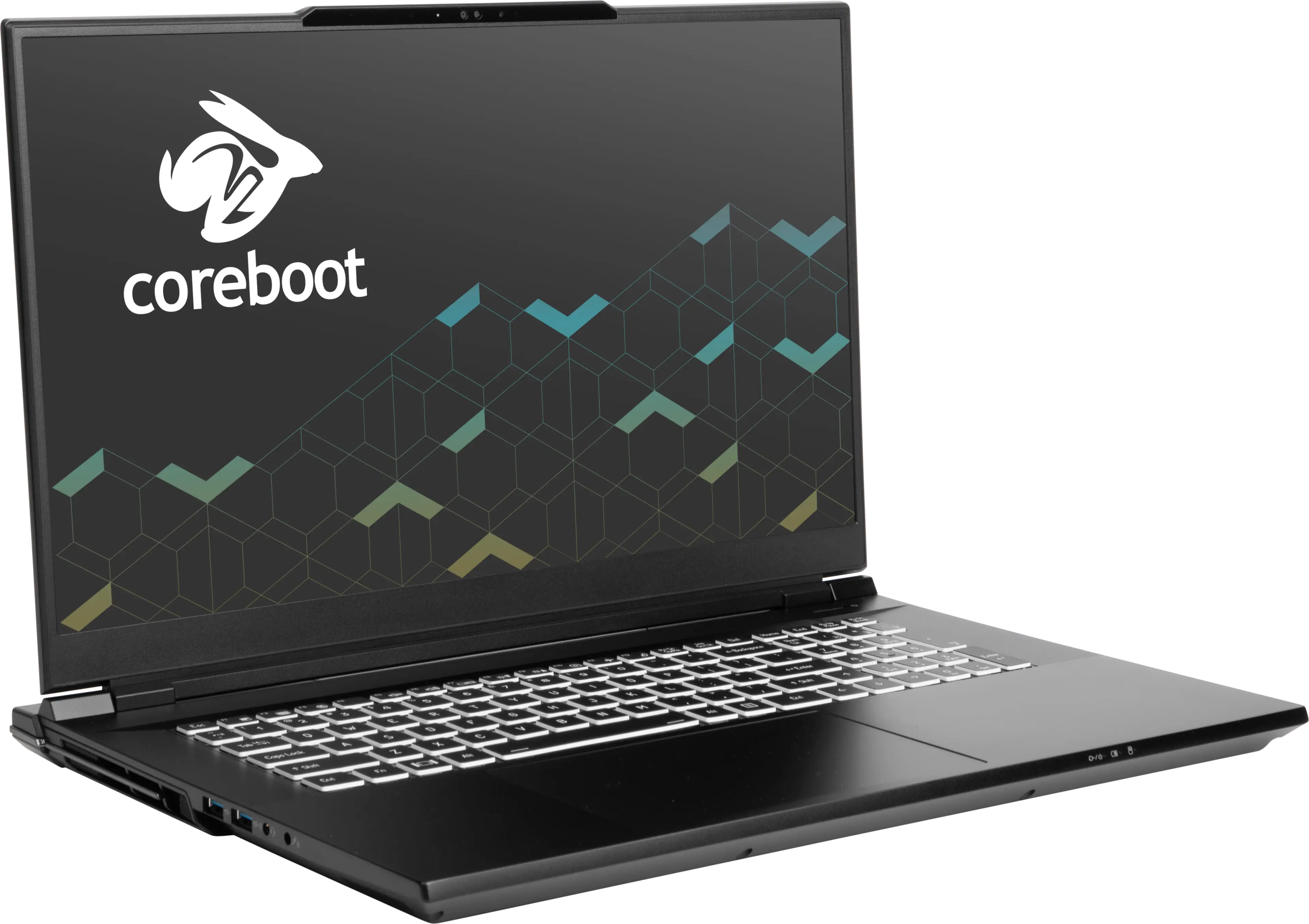
The System76 Bonobo WS is a laptop with the following specifications:
- CPU
- Supports Intel 13th & 14th Generation (Raptor Lake) CPUs
- Chipset
- BIOS
- GigaDevice GD25B256EYIGR flash chip
- WSON-8 form factor
- UEFI firmware dependent on model:
- bonw15-b: Programmed with System76 firmware (non-open)
- bonw15: Programmed with System76 Open Firmware
- GigaDevice GD25B256EYIGR flash chip
- EC
- ITE IT5570E
- EC firmware dependent on model:
- bonw15-b: Programmed with non-open EC firmware
- bonw15: Programmed with System76 EC
- Graphics
- GPU options:
- NVIDIA GeForce RTX 4090
- TGP: 150W (175W boost)
- NVIDIA GeForce RTX 4080
- TGP: 150W (175W boost)
- NVIDIA GeForce RTX 4090
- eDP display options:
- 17.3" 3840x2160@144Hz LCD
- LCD panel: BOE NE173QUM-NY1 (or equivalent)
- 17.3" 2560x1440@240Hz LCD
- LCD panel: BOE NE173QHM-NZ1 (or equivalent)
- 17.3" 3840x2160@144Hz LCD
- External video outputs:
- 1x HDMI 2.1
- 1x Mini DisplayPort 1.4
- 2x DisplayPort 1.4 over USB-C
- GPU options:
- Memory
- Up to 96GB (2x48GB) dual-channel DDR5 SO-DIMMs @ 5600 MHz
- Networking
- 2.5-Gigabit Ethernet
- M.2 PCIe/CNVi WiFi/Bluetooth options:
- Intel Wi-Fi 7 BE200
- Bluetooth 5.4
- Intel Wi-Fi 6E AX210/AX211
- Bluetooth 5.3
- Intel Wi-Fi 7 BE200
- Power
- 330W (19.5V, 16.92A) DC-in ports
- DC-in port accepts rectangular (not barrel) connector
- Included AC adapter: Chicony A20-330P1A
- AC power cord type: IEC C13
- 99Wh 8-cell Lithium-Ion battery
- Model number: X270BAT-8-99
- 330W (19.5V, 16.92A) DC-in ports
- Sound
- Internal speakers & microphone
- Combined headphone & microphone 3.5mm jack
- Combined microphone & S/PDIF (optical) 3.5mm jack
- HDMI, Mini DisplayPort, USB-C DisplayPort audio
- Storage
- 3x M.2 PCIe NVMe Gen 4
- USB
- 2x USB Type-C with Thunderbolt
- Thunderbolt version dependent on model:
- bonw15-b: Thunderbolt 5
- bonw15: Thunderbolt 4
- Thunderbolt version dependent on model:
- 2x USB 3.2 Gen 2 Type-A
- 2x USB Type-C with Thunderbolt
- Dimensions
- 2.49cm x 39.6cm x 27.8cm, 3.29kg
Bonobo WS (External Overview)
Left side overview:

Right side overview:

Front side overview:

Back side overview:

Keyboard & touchpad overview:

Materials:
| Part | Material | Part Number |
|---|---|---|
| LCD back cover (lid) | Aluminum | 6-39-X3701-022 |
| LCD front cover (bezel) | Plastic | 6-40-X3701-010 |
| Top case (palm rests/port covers) | Aluminum | 6-78-X370SNWG2-010 |
| Bottom panel | Aluminum | 6-39-X3703-011 |
| Back strip | Plastic | 6-42-X3703-101 |
LED indicators
The Bonobo WS has the following LED indicators:
| Icon | Color | Description |
|---|---|---|
 | Orange | Powered off, DC power plugged in |
| Green | Powered on | |
| Blinking green | Sleeping (suspended) | |
 | Orange | Battery charging |
| Green | Battery fully charged | |
| Blinking orange | Battery critically low | |
 | Green | Storage drive activity |
Keyboard Shortcuts
The Bonobo WS has the following actions available using the Fn and Function keys:
| Key | Shortcut | Action |
|---|---|---|
 | Fn+F1 | Toggle trackpad |
 | Fn+F2 | Toggle built-in LCD |
 | Fn+F3 | Mute |
 | Fn+F5 | Volume down |
 | Fn+F6 | Volume up |
 | Fn+F7 | Toggle displays |
 | Fn+F8 | Screen brightness down |
 | Fn+F9 | Screen brightness up |
 | Fn+F10 | Toggle webcam |
 | Fn+F11 | Toggle airplane mode |
 | Fn+F12 | Suspend |
 | Fn+` | Play/Pause |
 | Fn+* | Toggle keyboard backlight |
 | Fn+/ | Cycle keyboard color |
 | Fn+- | Decrease keyboard brightness |
 | Fn++ | Increase keyboard brightness |
| 1 | Fn+1 | Toggle fan between max/automatic |
Bonobo WS (Internal Overview)
Bottom components and connectors:

- LCD panel connector is highlighted in light green
- Webcam/microphone connector is highlighted in cyan
- Keyboard adhesive access point is highlighted in pink
- Wireless card is highlighted in navy
- M.2 SSDs are highlighted in dark green
- All slots support PCIe NVMe Gen 4
- Fan connectors are highlighted in orange
- CMOS battery connector is highlighted in purple
- Speaker connectors are highlighted in yellow
- Left speaker connector (on the right) is under SSD slot 3
- BIOS flash chip (U58) is highlighted in black
- Main battery connector is highlighted in red
- Touchpad connector is highlighted in white
- RAM is highlighted in maroon
Under-keyboard components and connectors:

- Keyboard connector is highlighted in yellow
- Keyboard backlight connectors are highlighted in green
- Power button/LED connector is highlighted in red
- Keyboard adhesive access point is highlighted in cyan
Bonobo WS (Parts & Repairs)
Many components in your Bonobo WS can be upgraded or replaced as necessary. Follow these step-by-step guides for instructions:
- Removing the bottom cover
- Replacing the battery
- Replacing the RAM
- Replacing an M.2/NVMe SSD
- Replacing the WiFi/Bluetooth module
- Replacing the CMOS battery
- Replacing the fans/heatsink/thermal paste
- Replacing the speakers
- Replacing the keyboard
Removing the bottom cover:
Removing the cover is required to access the internal components. Prior to removing the cover, ensure the AC power is unplugged and all peripherals (such as USB drives or Kensington locks) are unplugged or removed from the system.
Tools required: Cross-head (Phillips) screwdriver
Time estimate: 5 minutes
Difficulty: Easy ●
Steps to remove the bottom cover:
- Place the machine lid-side down.
- Use a soft surface (such as a towel) to avoid scratches.
- Remove the 16 bottom panel screws.

- Slide the back strip off the back of the machine.
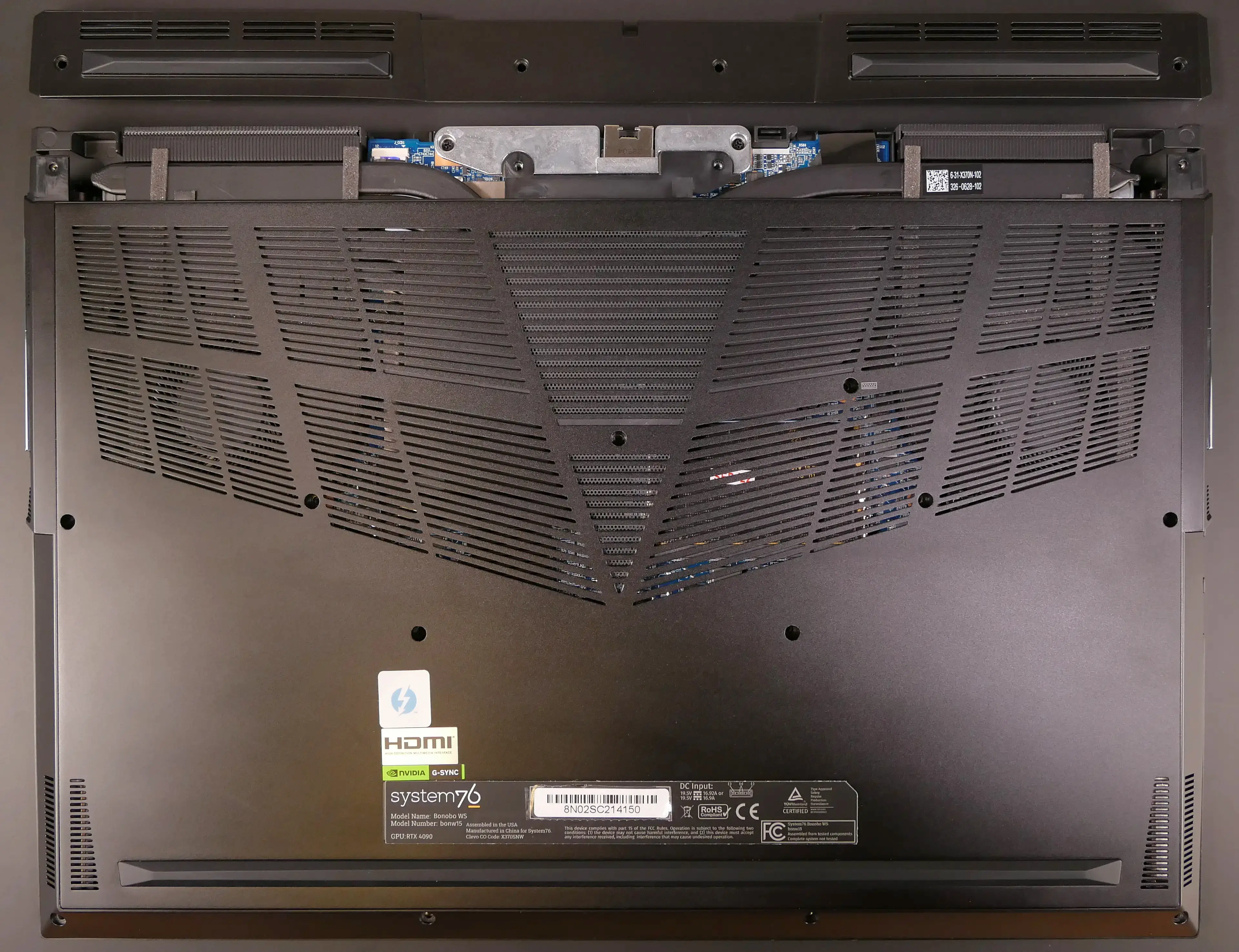
- Pull the bottom panel off, starting from the back.
Replacing the battery:
The battery provides primary power whenever the system is unplugged.
The model number for the Bonobo WS 15's battery is X270BAT-8-99, and the original part number is 6-87-X270S-92B01. Third-party battery sellers may list one or both of these numbers, and may offer other compatible part numbers with the same model number. You can also contact System76 to purchase a replacement battery.
Tools required: Cross-head (Phillips) screwdriver
Time estimate: 10 minutes
Difficulty: Easy ●
Steps to replace the battery:
- Follow the steps above to remove the bottom cover.
- Remove the four screws along the top of the battery.

- Unplug the white connector connecting the battery to the motherboard.
- Remove the battery, starting from the top edge with screw holes.
- When putting in the new battery, start with the plastic tabs along the bottom edge (opposite from the screw holes.)
- When plugging in the new battery, the red wire on the connector goes on the left, and the black wire goes on the right.
Replacing the RAM:
The Bonobo WS 15 supports up to 96GB (2x48GB) of DDR5 SO-DIMMs running at 5600MHz. If you've purchased new RAM, need to replace your RAM, or are reseating your RAM, follow these steps.
Tools required: Cross-head (Phillips) screwdriver
Time estimate: 10 minutes
Difficulty: Easy ●
Steps to replace the RAM:
- Follow the steps above to remove the bottom cover.
- Press the small tabs on both sides of the RAM simultaneously. The RAM should spring up to an angle.

- Remove the RAM from the slot.
- Insert the new RAM (or reseat the existing RAM) by placing it in the keyed slot and pressing down on the RAM until it clicks into place.
Replacing an M.2/NVMe SSD:
This model supports up to three M.2 SSDs. All M.2 slots are size 2280 and support PCIe NVMe Generation 4.
Tools required: Cross-head (Phillips) screwdriver
Time estimate: 10 minutes
Difficulty: Easy ●
Steps to replace the M.2 drive:
- Follow the steps above to remove the bottom cover.
- Unscrew the retainer screw opposite the M.2 slot.

- Remove the existing M.2 drive by pulling it out of the slot.
- Insert the new M.2 drive into the slot and hold it in place.
- Replace the retainer screw.
Replacing the wireless card:
Your Bonobo WS's WiFi and Bluetooth are both handled by the same module. It is a standard M.2 2230 slot with PCIe and USB interfaces (E-key).
Tools required: Cross-head (Phillips) screwdriver
Time estimate: 10 minutes
Difficulty: Medium ●
Steps to replace the WiFi/Bluetooth module:
- Follow the steps above to remove the bottom cover.
- Locate the wireless card. Remove any clear tape that is securing the wires.

- Gently remove the two antennas (highlighted red above) by pulling them up and away from the wireless card.
- Remove the retaining screw opposite the M.2 slot, highlighted yellow above.
- The wireless card will pop up at an angle. Remove the card from the M.2 slot.
- Insert the new wireless card into the M.2 slot at an angle.
- Hold the card down and replace the retaining screw.
- Attach the two antennas by aligning the circular fittings and pressing onto the wireless card. The connectors will snap into place. Use caution when attaching the connectors; the pins can bend, break, or snap.
Replacing the CMOS battery:
The CMOS battery supplies power to the system's CMOS chip. UEFI settings and the comptuer's hardware clock are stored on the CMOS. If your system doesn't boot, you can reset the CMOS to force a low-level hardware reset. If your clock is constantly resetting, it's likely your CMOS battery needs to be replaced.
Warning (ingestion hazard): Keep batteries out of reach of children. Death or serious injury can occur if ingested. If a battery is suspected to be swallowed or inserted inside any part of the body, seek immediate medical attention. In the US, you can also call the National Battery Ingestion Hotline for guidance: 1 (800) 498-8666
Tools required: Cross-head (Phillips) screwdriver
Time estimate: 10 minutes
Difficulty: Easy ●
Steps to replace the CMOS battery:
- Follow the steps above to remove the bottom cover.
- Unplug the white connector that connects the CMOS battery to the motherboard.
- If you are replacing the battery, gently pull from the sides to pry it up from where it's stuck to the case.

- To clear the CMOS, open the lid of the machine and hold down the power button for at least 15 seconds to discharge any residual energy in the system.
- Re-connect the CMOS battery and the main battery.
- Replace the SSDs and wireless card (if necessary) and the bottom panel.
- Power up the Bonobo WS. The system may power itself off and on after initial boot; this is normal behavior when the CMOS has been reset.
Replacing the cooling system:
The Bonobo WS 15 has a single heatsink assembly with two fans. This assembly cools the CPU and GPU.
If the fans become noisy and cleaning them out doesn't fix the issue, you may need a new fan. Contact support to start a warranty claim or parts purchase. These instructions can also be used if physical damage to the heatsink necessitates its replacement.
Thermal paste helps facilitate effective heat transfer between the CPU/GPU and the cooling equipment; depending on your climate and the age of the machine, replacing the thermal paste may improve cooling performance. The thermal paste should generally be replaced whenever the heatsink is removed.
Thermal putty (thicker than thermal paste) is used to bridge the gap between the VRAM chips and the heatsink. Replacing the thermal putty is optional when removing the heatsink. System76 suggests Thermal Grizzly Putty Basic (available at various retailers) or a similar alternative.
Tools required: Cross-head (Phillips) screwdriverthermal putty spreader (flat plastic tool)
Time estimate: 15 minutes
Difficulty: High ●
Steps to replace the heatsink/thermal paste:
- Follow the steps above to remove the bottom cover and remove any SSDs present in slots 2 and 3.
- Remove the thirteen heatsink and fan screws in order of the stamped numbers, starting with #1, then #2, and continuing until you have removed #13.
- Screws #1-#12 are held captive, and will not completely detatch from the heatsink/fans. Screw #13 is not held captive, and will come loose when untightened.
- Do not remove the smaller screws holding the fan covers onto the fans.

- Remove any clear tape covering the fan wires.
- The tape covering the wireless card antennas may also need to be removed.
- Unplug the black fan connectors from the motherboard.
- Remove the heatsink/fans from the case, being careful not to bend the heatsink pipes. It may take some pressure to break the seal of the thermal paste.
- Using a paper towel, remove the existing thermal paste from the CPU, GPU, and heatsink. You may also use a small amount of rubbing alcohol if the old paste is dried or difficult to remove.
- You can optionally remove the thermal putty from the eight VRAM chips surrounding the GPU chip if you have replacement thermal putty to install.

- Apply a small line of thermal paste directly onto the CPU chip and the GPU chip.
- If you're also replacing the thermal putty, apply the new putty to the eight VRAM chips.
- If you aren't replacing the thermal putty, scoop the existing putty (from the VRAM chip and the corresponding location on the heatsink) into the center of each VRAM chip using a flat plastic tool.

- Carefully replace the heatsink.
- Replace the fan and heatsink screws, starting with #1, then #2, and so on until #13.
- Plug the black fan connectors back into the motherboard and (optionally) replace the clear tape.
Replacing the speakers:
The system has two bottom-firing speakers, which can be removed and replaced individually.
Tools required: Cross-head (Phillips) screwdriver
Time estimate: 10 minutes
Difficulty: Medium ●
Steps to replace the left speaker:
- Follow the steps above to remove the bottom cover and remove any SSDs present in slots 2 and 3.
- Remove the two screws holding the audio daugherboard onto the chassis, then flip the audio daughterboard over towards the motherboard.
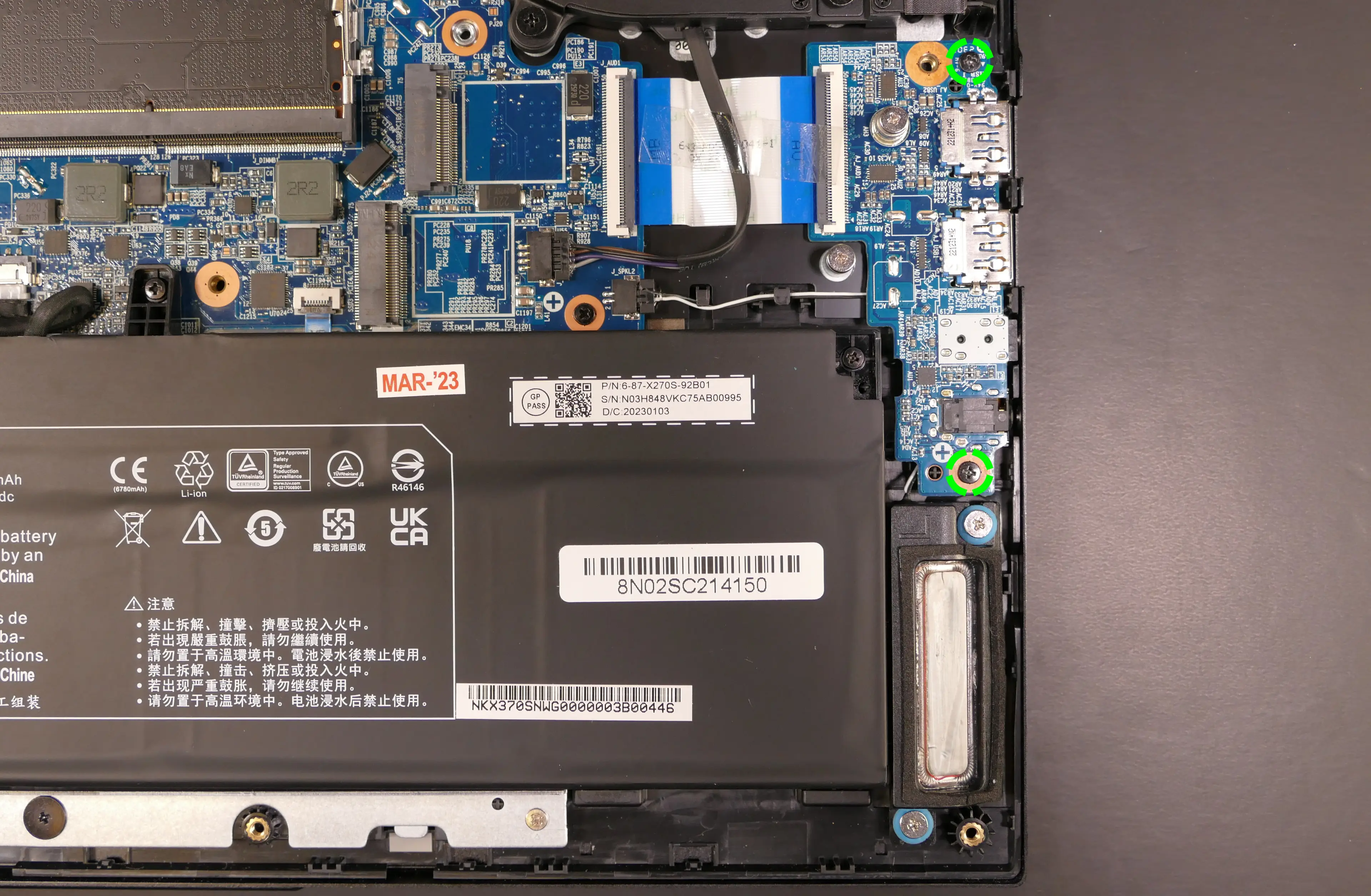
- Disconnect the speaker connector from the motherboard.
- This can alternatively be done after freeing the speaker.

- Unscrew the two speaker screws, free the speaker wire from the channels in the chassis, and remove the speaker.
- Screw in the new speaker and connect it to the motherboard, securing the wire using the channels in the chassis.
- Replace the audio daughterboard and bottom cover.
Steps to replace the right speaker:
- Follow the steps above to remove the bottom cover.
- Disconnect the speaker connector from the motherboard.
- This can alternatively be done after freeing the speaker.

- Unscrew the two speaker screws and remove the speaker.
- Screw in the new speaker and connect it to the motherboard.
- Replace the bottom cover.
Replacing the keyboard:
The keyboard includes per-key RGB LED backlighting, and can be replaced using the instructions below.
Warning: Removing the keyboard may cause permanent aesthetic damage to the underside of the keyboard, particularly if the adhesive strip is not fully removed first. Removal is not recommended unless the keyboard is malfunctioning.
Tools required: Cross-head (Phillips) screwdriver; tweezers (optional)
Time estimate: 10 minutes
Difficulty: High ●
Steps to replace the keyboard:
- Follow the steps above to remove the bottom cover.
- Pull the keyboard adhesive out of the machine to detatch it from the keyboard.
- The adhesive strip access point is highlighted green below.
- If the end of the keyboard adhesive strip is tucked behind the fan, it can be pulled out using tweezers or a small screwdriver, or the thermal system can be removed to expose it.
- Replacing the thermal paste is recommended if the thermal system is removed.
- If the adhesive strip breaks, remove as much of it as possible. The keyboard can be reinstalled without the adhesive strip.

- Open the lid slightly and place the machine on its side.
- Push a screwdriver into the keyboard push point (highlighted red above) until the keyboard pops out.

- Set the machine back down and raise the keyboard away from the chassis. The largest ribbon cable is for the keyboard, while the smaller ribbon cables are for the keyboard backlight.

- Flip the black latches upwards to free the ribbon cables.
- Pull the ribbon cables out of the connectors.
- Remove the keyboard and replace it with the new one.
- Carefully slide all three ribbon cables into their connectors.
- Flip the black latches back into place to secure the ribbon cables.
- (Optional) Replace the keyboard adhesive strip on the chassis.
- Place the keyboard back into position, starting with the tabs on the bottom edge.
- Secure the rest of the keyboard by pressing down on each of its edges.
- Turn the machine lid-side down again.
- Replace the bottom cover.
Bonobo WS (bonw14)
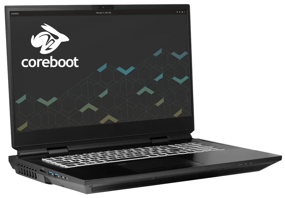
The System76 Bonobo WS is a laptop with the following specifications:
- CPU
- Supports Intel 10th Generation (Comet Lake) Desktop CPUs
- Chipset
- BIOS
- GD25B127D flash chip
- SOIC-8 form factor
- Programmed with System76 Open Firmware
- GD25B127D flash chip
- EC
- ITE IT5570E
- Programmed with System76 EC
- Graphics
- GPU options:
- NVIDIA GeForce RTX 2080 Super
- NVIDIA GeForce RTX 2070 Super
- NVIDIA GeForce RTX 2060
- eDP display options:
- 17.3" 1920x1080@144Hz LCD
- LCD panel: LG LP173WFG-SPB1 (or equivalent)
- 17.3" 3840x2160@60Hz LCD
- LCD panel: AUO B173ZAN03.0 (or equivalent)
- 17.3" 1920x1080@144Hz LCD
- External video outputs:
- 1x HDMI
- 2 x Mini DisplayPort 1.4
- 2 x DisplayPort 1.4 over USB-C
- GPU options:
- Memory
- Up to 128GB (4x32GB) quad-channel DDR4 SO-DIMMs @ 3200 MHz
- Networking
- Gigabit Ethernet
- M.2 PCIe/CNVi WiFi/Bluetooth
- Intel Wi-Fi 6 AX200/AX201
- Power
- 2x 280W (20V, 14A) DC-in ports
- DC-in ports accept rectangular (not barrel) connectors
- Included AC adapters: 2x Chicony A18-280P1A
- AC power cord type: IEC C13 (one per AC adapter)
- 97Wh 8-cell Lithium-Ion battery
- Model number: X170BAT-8
- 2x 280W (20V, 14A) DC-in ports
- Sound
- Internal speakers (stereo + subwoofer) & microphone
- Combined headphone & microphone 3.5mm jack
- Combined microphone & S/PDIF (optical) 3.5mm jack
- HDMI, Mini DisplayPort, USB-C DisplayPort audio
- Storage
- 4x M.2
- 2x PCIe NVMe or SATA
- 1x PCIe only
- 1x SATA only
- SD card reader
- 4x M.2
- USB
- 3x USB 3.2 Gen 2 Type-A
- 1x USB Type-C with Thunderbolt 3
- 1x USB 3.2 Gen 2 Type-C with DisplayPort 1.4
- 1x USB 3.2 Gen 2x2 Type-C
- Dimensions
- 4.343cm x 39.903cm x 31.902cm, 3.80kg
Bonobo WS (External Overview)
Left side overview:

Right side overview:

Front side overview:

Back side overview:

Keyboard Shortcuts
The Bonobo WS has the following actions available using the Fn and Function keys:
| Key | Shortcut | Action |
|---|---|---|
 | Fn+F1 | Toggle trackpad |
 | Fn+F2 | Toggle built-in LCD |
 | Fn+F3 | Mute |
 | Fn+F5 | Volume down |
 | Fn+F6 | Volume up |
 | Fn+F7 | Toggle displays |
 | Fn+F8 | Screen brightness down |
 | Fn+F9 | Screen brightness up |
 | Fn+F10 | Toggle webcam |
 | Fn+F11 | Toggle airplane mode |
 | Fn+F12 | Suspend |
 | Fn+` | Play/Pause |
 | Fn+* | Toggle keyboard backlight |
| / | Fn+/ | Cycle keyboard color |
| - | Fn+- | Decrease keyboard brightness |
| + | Fn++ | Increase keyboard brightness |
LED indicators
The Bonobo WS has the following LED indicators:
| Icon | Color | Description |
|---|---|---|
 | Orange | Powered off, DC power plugged in |
| Green | Powered on | |
| Blinking green | Sleeping (suspended) | |
 | Orange | Battery charging |
| Green | Battery fully charged | |
| Blinking orange | Battery critically low | |
 | Green | Storage drive activity |
Bonobo WS (Internal Overview)
Bottom components and connectors:

- LED bar is highlighted in purple
- Fan/heatsink module is highlighted in white
- Keyboard screwholes are highlighted in red
- Fan connectors are highlighted in pink
- M.2 SSDs are highlighted in cyan
- RAM (slots 1 and 3) are highlighted in green
- CMOS battery is highlighted in yellow
- Battery slot is highlighted in orange
- Speakers are highlighted in olive
Under-keyboard components and connectors:

- Keyboard connector is highlighted in red
- Keyboard backlight connectors are highlighted in light green
- RAM (slots 2 and 4) are highlighted in cyan
- Wireless card is highlighted in orange
- 3.5mm audio jack connector is highlighted in maroon
- SD card slot connector is highlighted in yellow
- Power button/LED connector is highlighted in pink
- Front LED connector is highlighted in navy
- Touchpad connector is highlighted in purple
- Keyboard & keyboard backlight board to motherboard connector is highlighted in olive
- BIOS flash chip (U16), not highlighted
Bonobo WS (Parts & Repairs)
Many components in your Bonobo WS can be upgraded or replaced as necessary. Follow these step-by-step guides for instructions:
- Removing the bottom cover
- Removing the battery
- Replacing the keyboard
- Replacing the RAM
- Replacing an M.2/NVMe SSD
- Replacing the WiFi/Bluetooth module
- Replacing the CMOS battery
- Replacing the fans/heatsink/thermal paste
- Replacing the CPU
- Replacing the GPU
Removing the bottom cover:
Removing the cover is required to access the internal components. Prior to removing the cover, ensure the AC power is unplugged and all peripherals (including SD cards and USB drives) are unplugged or removed from the system.
Tools required: Cross-head (Phillips) screwdriver
Time estimate: 5 minutes
Difficulty: Easy ●
Steps to remove the bottom cover:
- Place the machine lid-side down.
- Use a soft surface (such as a towel) to avoid scratches.
- Remove the 8 bottom panel screws (highlighted red below.)

- Slide the bottom panel away from the battery slot while lifting it up and off of the case (the panel detaches at a slight angle.)
Removing the battery:
The battery provides primary power whenever the system is unplugged.
The model number for the Bonobo WS 14's battery is X170BAT-8, and the original part number is 6-87-X17SS-91C01. Third-party battery sellers may list one or both of these numbers, and may offer other compatible part numbers with the same model number. You can also contact System76 to purchase a replacement battery.
Tools required: Cross-head (Phillips) screwdriver
Time estimate: 5 minutes
Difficulty: Easy ●
Steps to remove the battery:
- Place the machine lid-side down.
- Use a soft surface (such as a towel) to avoid scratches.
- Follow the steps above to remove the bottom cover. (Removing the bottom cover is optional, but can make removing the battery significantly easier.)
- Slide the locking battery slider (highlighted green below) to the "unlocked" position.

- Hold the spring-loaded battery slider (highlighted yellow above) in the "unlocked" position.
- Starting from the top, lift the battery up and out of the slot.
Replacing the keyboard:
The keyboard can be replaced using the instructions below.
Tools required: Cross-head (Phillips) screwdriver
Time estimate: 10 minutes
Difficulty: Medium ●
Steps to replace the keyboard:
- Follow the steps above to remove the bottom cover and remove the battery.
- Remove the two keyboard screws (circled yellow below.)

- Open the lid slightly and place the machine on its side.
- Push the screwdriver into the keyboard push point (highlighted cyan above) until the keyboard pops out.
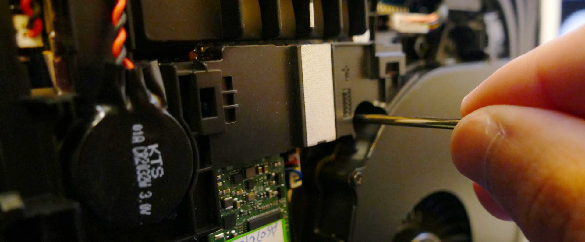
- Set the Bonobo WS back down and raise the keyboard away from the chassis. The largest ribbon cable (highlighted red below) is for the keyboard, while the two smaller ribbon cables (highlighted green) are for the keyboard backlight.

- Flip the black latches upwards to free the ribbon cables.
- Pull the ribbon cables out of the connectors.
- Remove the keyboard and replace it with the new one.
- Carefully slide all three ribbon cables into their connectors.
- Flip the black latches back into place to secure the ribbon cables.
- Place the keyboard back into position, starting with the tabs on the bottom edge.
- Secure the rest of the keyboard by pressing down on each of its edges.
- Turn the machine lid-side down again.
- Replace the 2 keyboard screws, the battery, and the bottom panel.
- Boot the machine and confirm the keyboard and keyboard backlight are operational.
Replacing the RAM:
The Bonobo WS 14 supports up to 128GB (4x32GB) of DDR4 SO-DIMMs running at 3200MHz. If you've purchased new RAM, need to replace your RAM, or are reseating your RAM, follow these steps.
Tools required: Cross-head (Phillips) screwdriver
Time estimate: 10 minutes
Difficulty: Medium ●
Steps to replace the RAM:
- Follow the steps above to remove the bottom cover and remove the battery.
- Two RAM slots are located on the bottom of the machine, while two are underneath the keyboard. If necessary, follow the steps above to remove the keyboard.
- Press the small tabs on both sides of the RAM simultaneously. The RAM should spring up to an angle.

- Remove the RAM from the slot.
- Insert the new RAM (or reseat the existing RAM) by placing it in the keyed slot and pressing down on the RAM until it clicks into place.
Replacing an M.2/NVMe SSD:
This model supports up to four M.2 SSDs. All M.2 slots are size 2280.
Tools required: Cross-head (Phillips) screwdriver
Time estimate: 10 minutes
Difficulty: Easy ●
Steps to replace the M.2 drive:
- Follow the steps above to remove the bottom cover and remove the battery.
- If working with any of the PCIe NVMe-capable slots, unscrew the three screws (highlighted red below) and remove the black metal cover from above those three slots.

- Unscrew the retainer screw opposite the M.2 slot.

In the above photo, the red slot is SATA only, the yellow slot is PCIe NVMe only, and the two orange slots work with SATA or PCIe NVMe.
- Remove the existing M.2 drive by pulling it out of the slot.
- Insert the new M.2 drive into the slot and hold it in place.
- Replace the retainer screw.
Replacing the wireless card:
Your Bonobo WS's WiFi and Bluetooth are both handled by the same module. It is a standard M.2 2230 slot with PCIe and USB interfaces (E-key).
Tools required: Cross-head (Phillips) screwdriver
Time estimate: 10 minutes
Difficulty: Medium ●
Steps to replace the WiFi/Bluetooth module:
- Follow the steps above to remove the bottom cover, remove the battery, and remove the keyboard.
- Locate the wireless module. Remove any clear tape that is securing the wires.

- Gently remove the two antennas (highlighted red above) by pulling them up and away from the wireless card.
- Remove the retaining screw opposite the M.2 slot, highlighted green above.
- The wireless card will pop up at an angle. Remove the card from the M.2 slot.
- Insert the new wireless card into the M.2 slot at an angle.
- Replace the retaining screw.
- Attach the two antennas by aligning the circular fittings and pressing onto the wireless card. The connectors will snap into place. Use caution when attaching the connectors; the pins can bend, break, or snap.
- Replace the keyboard, battery, and bottom cover.
Replacing the CMOS battery:
The CMOS battery supplies power to the system's CMOS chip. UEFI settings and the computer's hardware clock are stored on the CMOS. If your system doesn't boot, you can reset the CMOS to force a low-level hardware reset. If your clock is constantly resetting, it's likely your CMOS battery needs to be replaced.
Warning (ingestion hazard): Keep batteries out of reach of children. Death or serious injury can occur if ingested. If a battery is suspected to be swallowed or inserted inside any part of the body, seek immediate medical attention. In the US, you can also call the National Battery Ingestion Hotline for guidance: 1 (800) 498-8666
Tools required: Cross-head (Phillips) screwdriver
Time estimate: 10 minutes
Difficulty: Easy ●
Steps to replace the CMOS battery:
- Follow the steps above to remove the bottom cover and remove the main battery.
- Unplug the white connector attaching the CMOS battery to the motherboard (highlighted green below.)
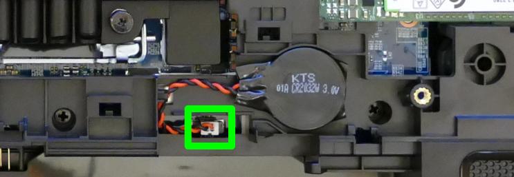
- If you are replacing the CMOS battery, pull it away from the adhesive holding it to the case.
- To clear the CMOS, open the lid of the machine and hold down the power button for at least 15 seconds to discharge any residual energy in the system.
- Re-connect the CMOS battery, replace the main battery, and replace the bottom panel.
- Power up the Bonobo WS. The system may power itself off and on after initial boot; this is normal behavior when the CMOS has been reset.
Replacing the cooling system:
The Bonobo WS 12 has a single heatsink assembly with two fans for the CPU and GPU.
If the fans become noisy and cleaning them out doesn't fix the issue, you may need a new fan. Contact Support to start a warranty claim or parts purchase.
Depending on your climate and the age of the machine, it may be necessary to apply new thermal paste between the CPU/GPU and the heatsink. Thermal paste helps facilitate effective heat transfer between the CPU/GPU and the cooling equipment. These instructions can also be used in the unlikely event your heatsink needs replacing.
Tools required: Cross-head (Phillips) screwdriver, thermal paste
Time estimate: 20 minutes
Difficulty: High ●
Steps to replace the heatsink/thermal paste:
- Follow the steps above to remove the bottom cover and remove the battery.
- Remove the three LED bar screws (highlighted green below).

- Raise the black latch on the ribbon cable connector (highlighted red above) to free the ribbon cable, then remove the ribbon cable; gently peel the cable away from any adhesive present.
- Remove the LED light bar.
- Remove the black metal M.2 cover. Removing the M.2 cover is optional, but makes it easier to free the fan wires later.
- Remove the eight fan screws (highlighted yellow below.)
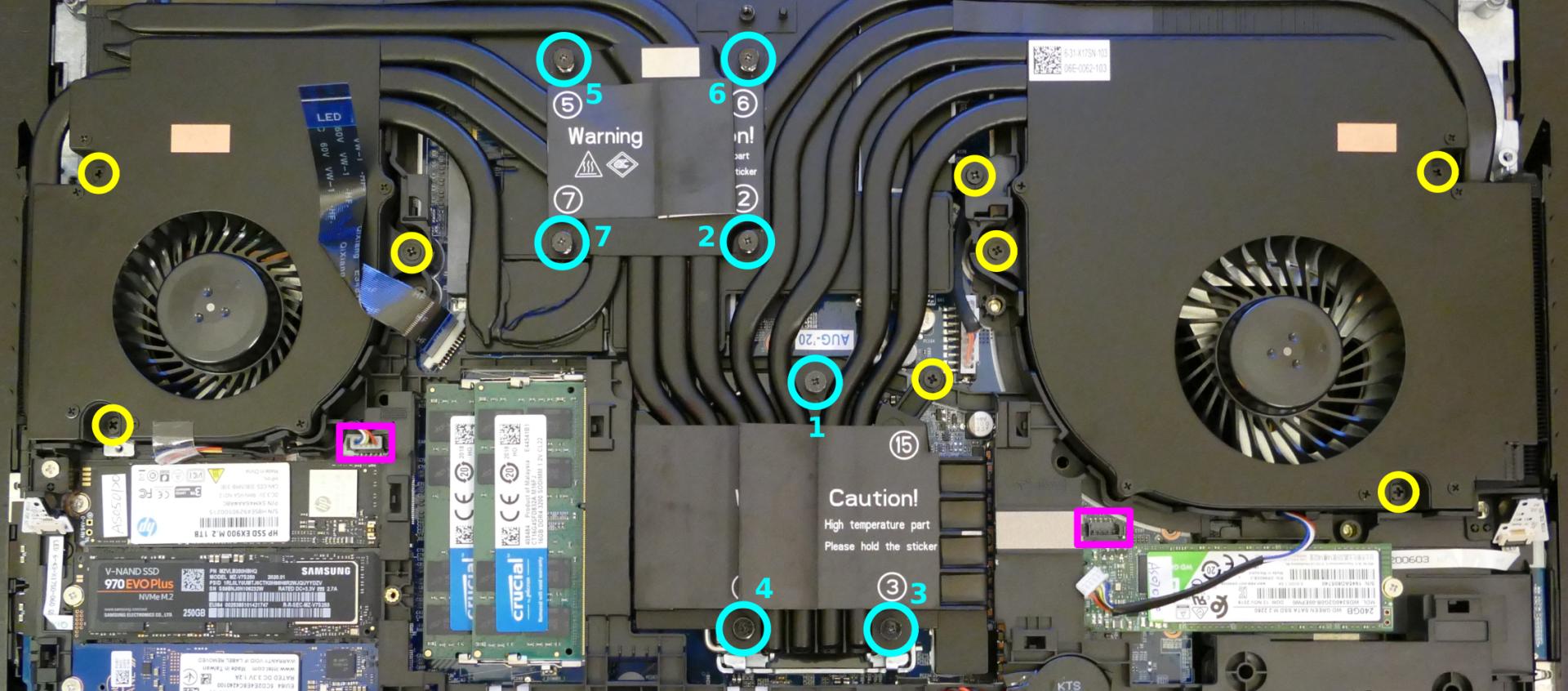
- Remove the seven spring-loaded heatsink screws (highlighted cyan above) in reverse order, starting with #7, then #6, and continuing until you have removed #1. Keep the four GPU heatsink screws separated from the three CPU heatsink screws; they are different sizes.
- Unplug the white fan connectors from the black sockets on the motherboard (highlighted pink above.) Remove any clear tape holding the fan wires in place.
- Remove the heatsink/fans from the case, being careful not to bend the heatsink pipes. It may take some pressure to break the seal of the thermal paste.
- Using a paper towel, remove the existing thermal paste. You may also use a small amount of rubbing alcohol if the old paste is dried or difficult to remove.
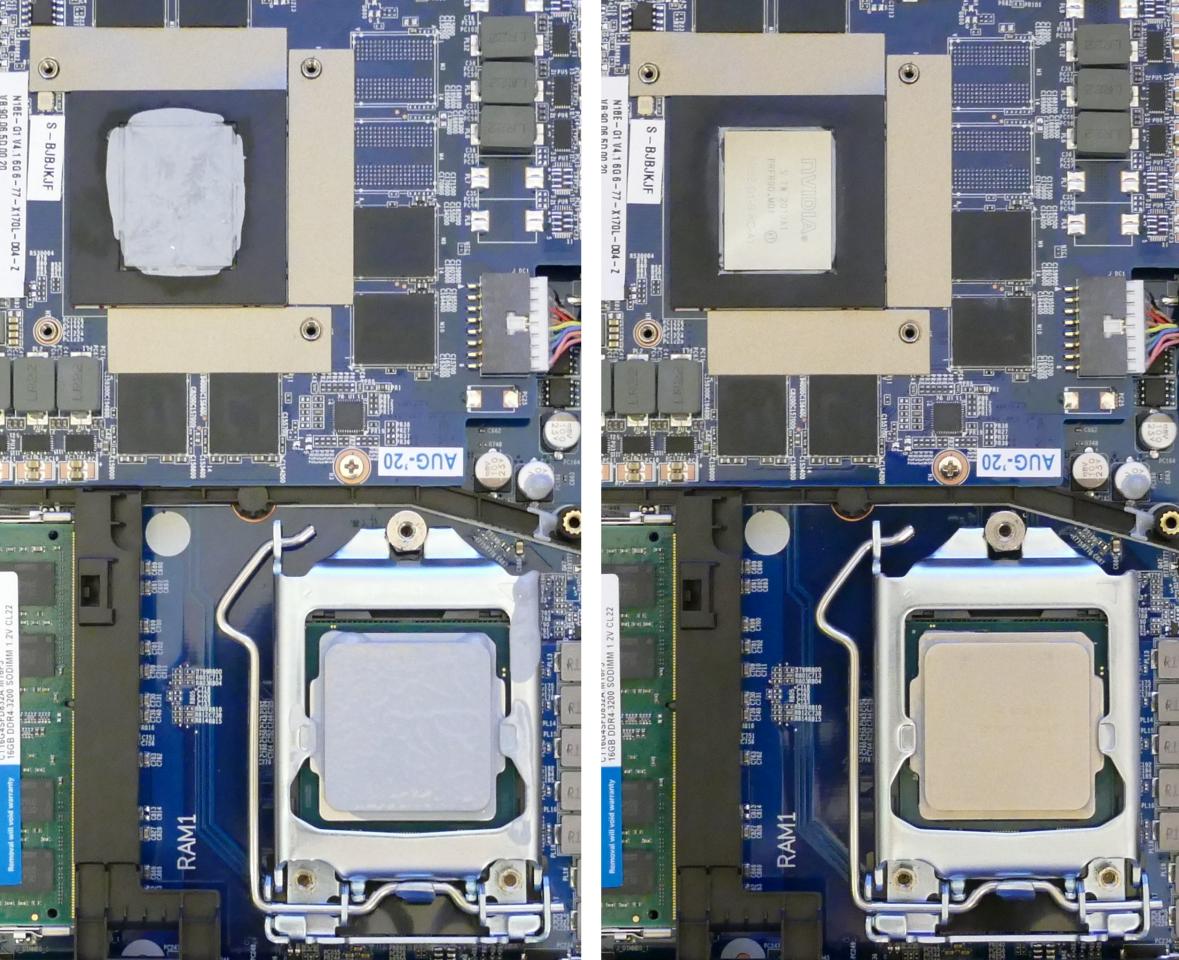
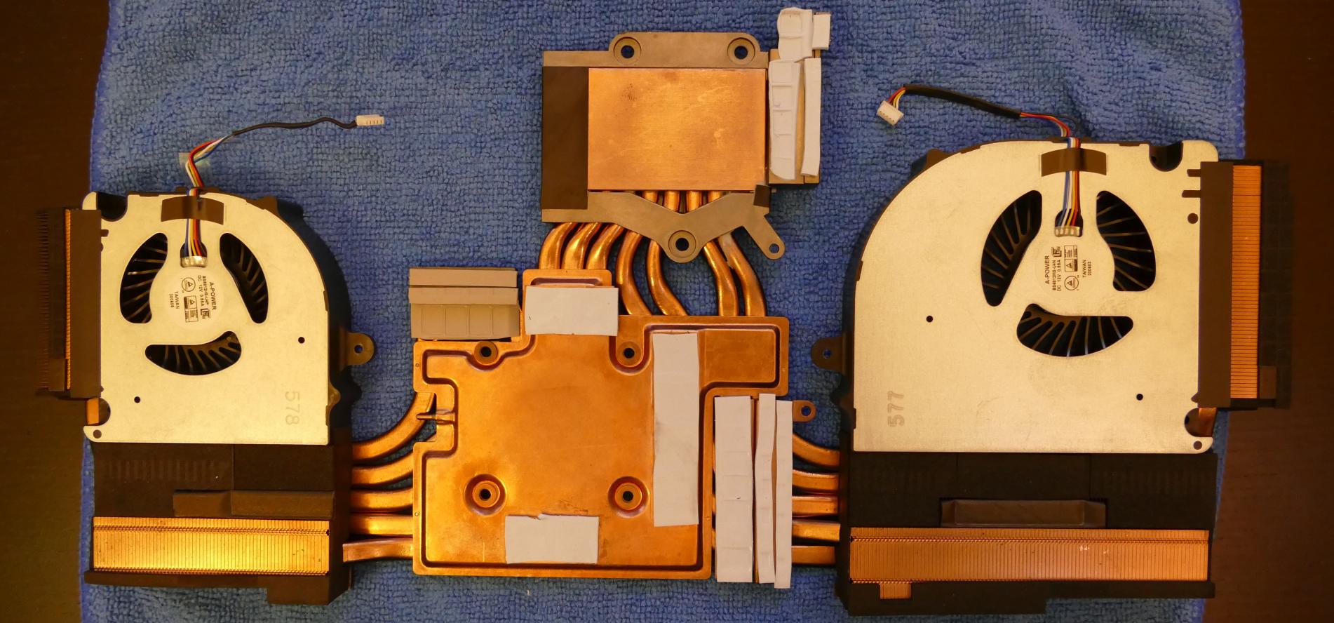
- After cleaning the CPU, GPU, and heatsink, apply a small line of thermal paste directly onto the CPU and GPU chips.
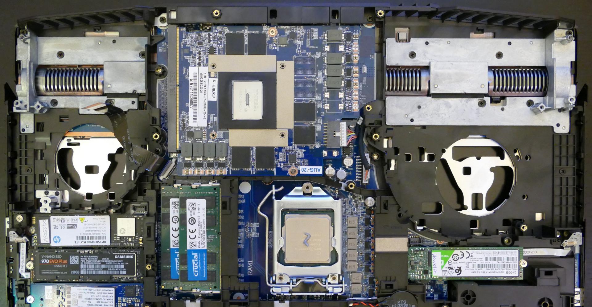
- Carefully replace the heatsink.
- Replace the spring-loaded heatsink screws, starting with #1, then #2, and so on until #7. The three screws over the CPU are slightly thicker, while the four screws over the GPU are slightly thinner.
- Replace the eight fan screws.
- Plug the white fan connectors back into the motherboard.
Replacing the CPU:
The Bonobo WS uses an LGA 1200 socket for the CPU. If you are upgrading or replacing your CPU, follow the steps below.
Tools required: Cross-head (Phillips) screwdriver
Time estimate: 25 minutes
Difficulty: High ●
Steps to replace the CPU:
- Follow the steps above to remove the bottom cover, remove the battery, and remove the heatsink.
- Lift up the lever holding the CPU cover in place, highlighted red below.
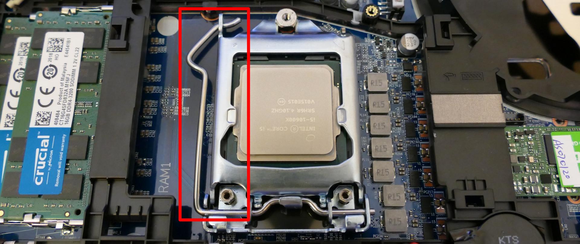
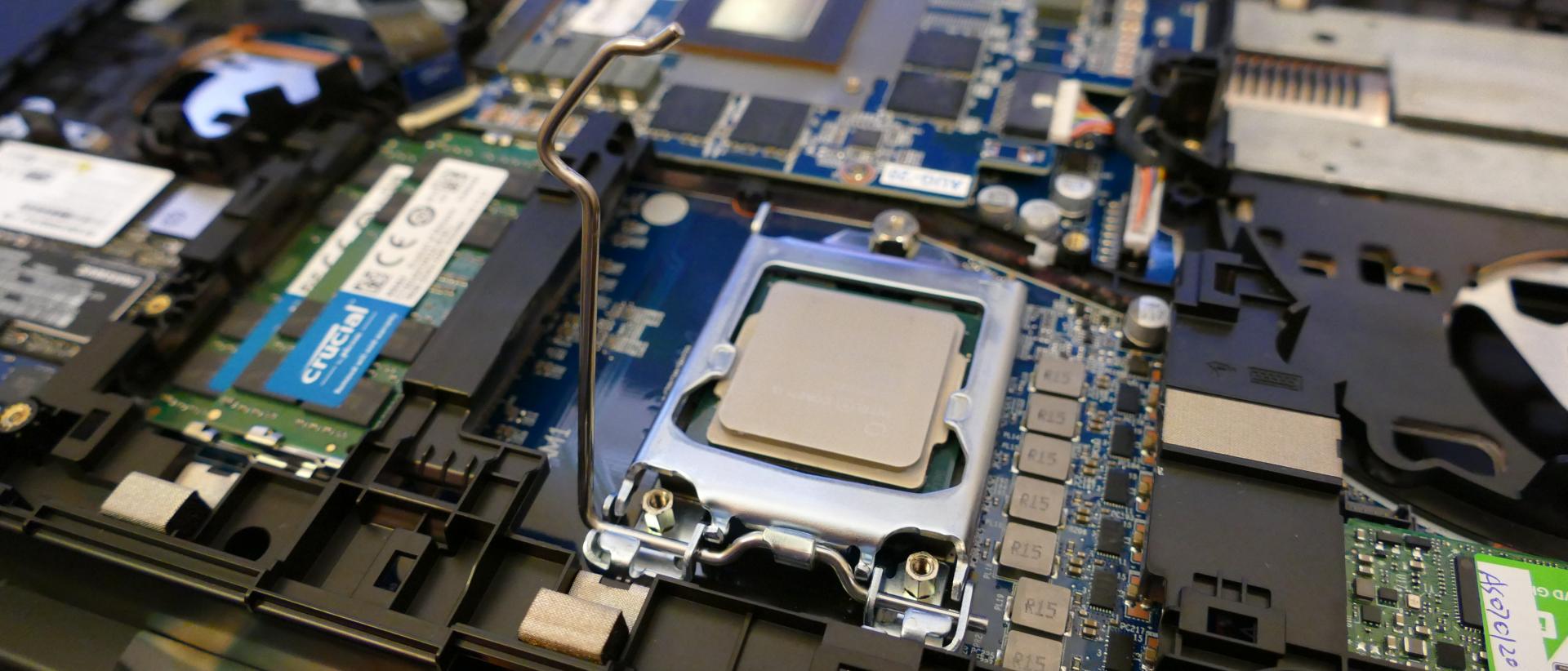
- Flip over the CPU cover.
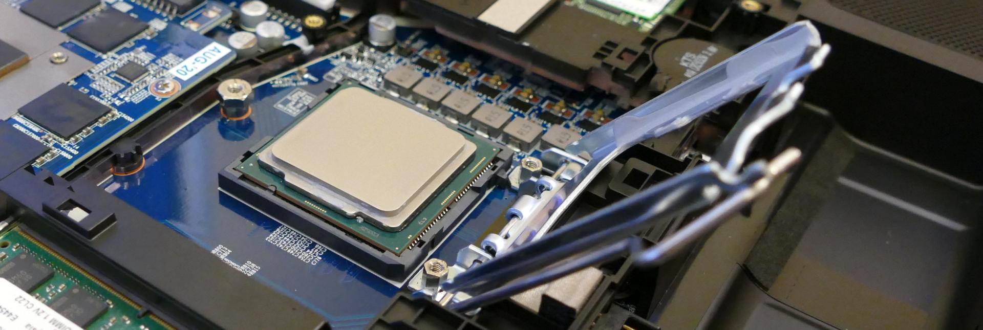
- Carefully lift the old CPU out of the socket. Caution: Be careful not to bend any of the gold pins in the CPU socket, and do not touch the gold plates on the bottom of the CPU.
- Carefully place the new CPU into the socket. One of the corners of the socket and CPU are marked with a triangle; be sure to match the triangles to the same corner so the CPU is placed in the correct orientation (highlighted yellow below.)
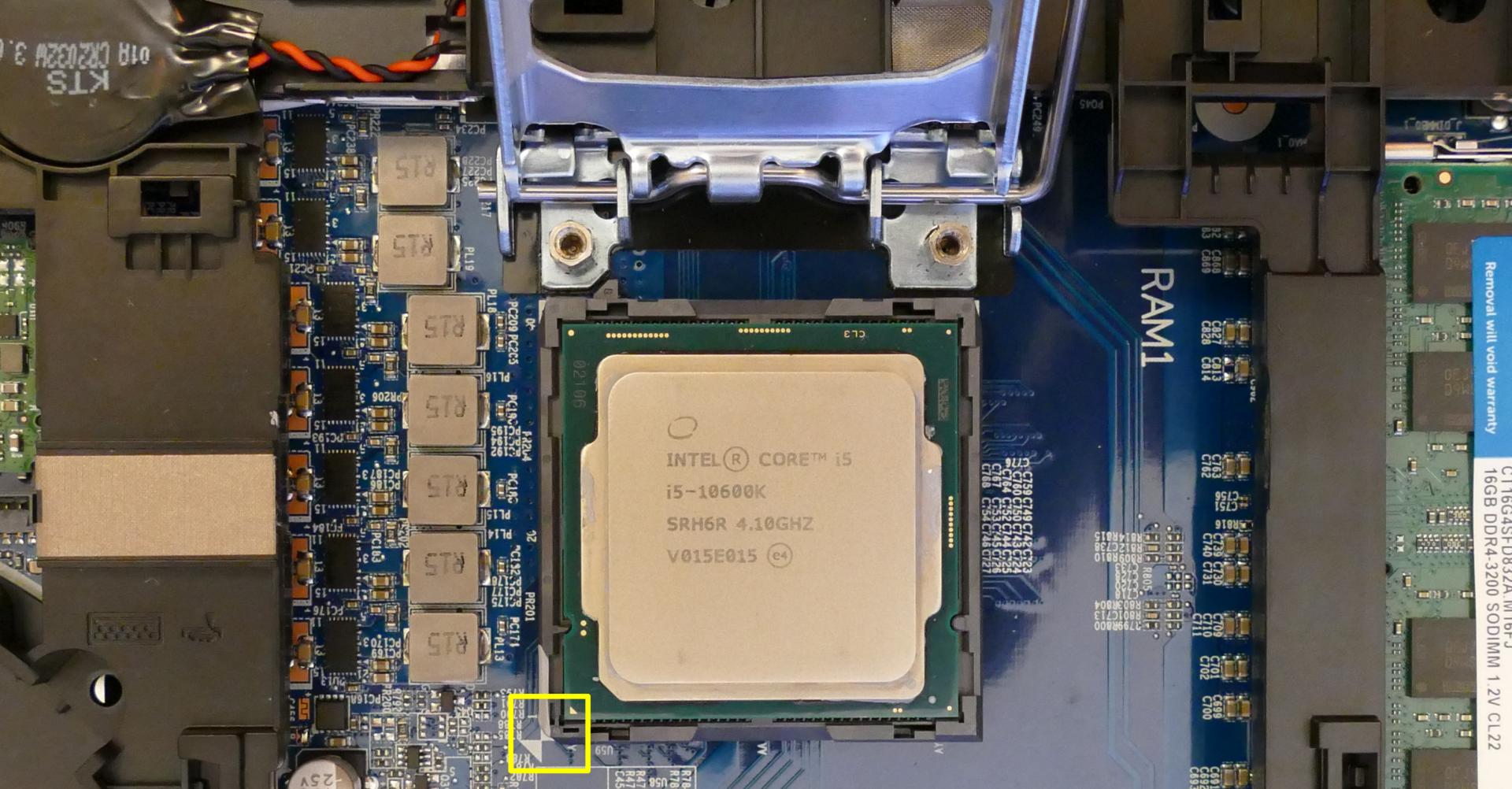
- Once the CPU is placed in the correct orientation, replace the CPU cover and lower the lever back down; lowering the lever may take some force.
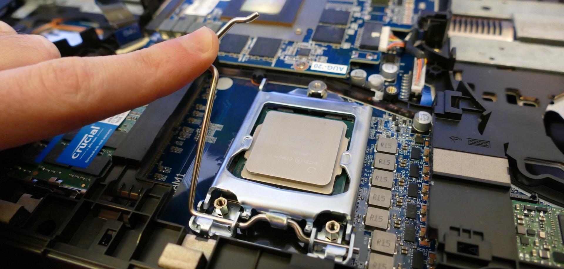
- Replace the thermal paste, heatsink/fan(s), battery, and bottom panel.
Replacing the GPU:
The Bonobo WS uses an MXM III slot for the GPU. If you are upgrading or replacing your GPU, follow the steps below.
Tools required: Cross-head (Phillips) screwdriver
Time estimate: 25 minutes
Difficulty: High ●
Steps to replace the GPU:
- Follow the steps above to remove the bottom cover, remove the battery, and remove the heatsink.
- Unplug the power cable, highlighted cyan below.
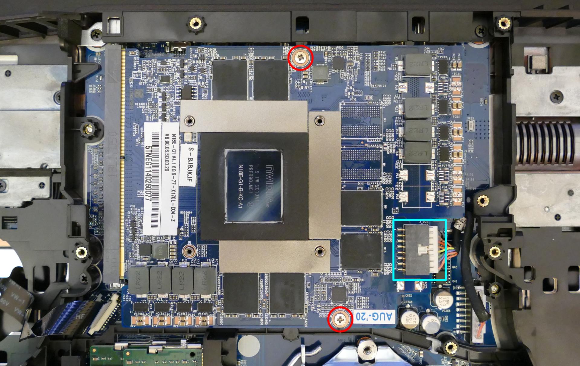
- Unscrew the two screws, highlighted red above.
- Raise the GPU to an angle and remove it from the slot.

- Place the new GPU (or reseat the existing GPU) into the slot at an angle, then hold it down and replace the screws and connector.
- Replace the thermal paste, heatsink/fan(s), battery, and bottom panel.
Darter Pro (darp10 & darp10-b)
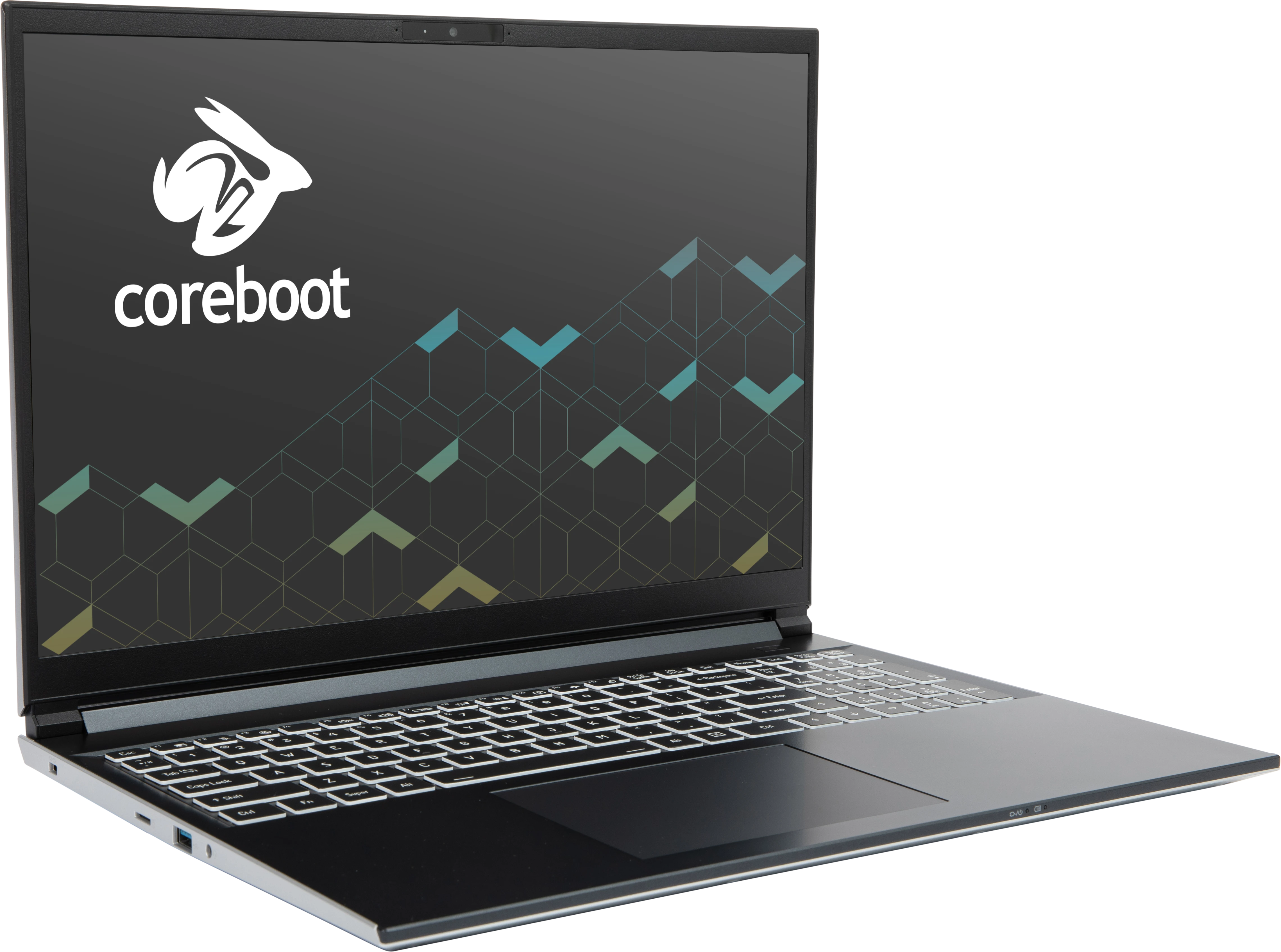
The System76 Darter Pro is a laptop with the following specifications:
- CPU
- Supports Intel Core Ultra 1st generation (Meteor Lake) CPUs
- BIOS
- XMC XM25QU256CXIQT08S flash chip
- WSON-8 form factor
- Programmed with System76 Open Firmware
- XMC XM25QU256CXIQT08S flash chip
- EC
- ITE IT5570E
- Programmed with System76 EC
- Graphics
- GPU: Intel Arc Graphics
- eDP display:
- 16" 1920x1200@60Hz LCD (darp10)
- LCD panel: AUO B160UAN03.0 (or equivalent)
- Brightness: 250 nits (cd/m²)
- sRGB color coverage: 65%
- LCD panel: AUO B160UAN03.0 (or equivalent)
- 14" 1920x1200@60Hz LCD (darp10-b)
- LCD panel: Innolux N140JCA-ELL (or equivalent)
- Brightness: 300 nits (cd/m²)
- sRGB color coverage: 66%
- LCD panel: Innolux N140JCA-ELL (or equivalent)
- 16" 1920x1200@60Hz LCD (darp10)
- External video outputs:
- 1x HDMI 2.1
- 1x DisplayPort 2.1 over USB-C
- Memory
- Up to 96GB (2x48GB) dual-channel DDR5 SO-DIMMs @ 5600 MHz
- Networking
- Gigabit Ethernet
- M.2 PCIe/CNVi WiFi/Bluetooth options:
- Intel Wi-Fi 7 BE200
- Bluetooth 5.4
- Intel Wi-Fi 6E AX210/AX211
- Bluetooth 5.3
- Intel Wi-Fi 7 BE200
- Power
- 90W (19V, 4.74A) DC-in port
- Barrel size: 5.5mm (outer), 2.5mm (inner)
- Included AC adapter: Chicony A16-090P1A
- AC power cord type: IEC C5
- USB-C charging compatible with 90W+ charger
- 73Wh 4-cell Lithium-ion battery
- Model number: V540BAT-4-73
- 90W (19V, 4.74A) DC-in port
- Sound
- Internal speakers & microphone
- Combined headphone & microphone 3.5mm jack
- HDMI, USB-C DisplayPort audio
- Storage
- 2x M.2 (PCIe NVMe Gen 4)
- MicroSD card reader
- USB
- 1x USB Type-C with Thunderbolt 4
- Supports DisplayPort over USB-C
- Supports USB-C charging (USB-PD)
- 1x USB 3.2 Gen 2 Type-C
- 1x USB 3.2 Gen 2 Type-A
- 1x USB 3.2 Gen 1 Type-A
- 1x USB Type-C with Thunderbolt 4
- Dimensions
- 16" model (darp10): 1.8cm x 35.8cm x 25.86cm, 1.75kg
- 14" model (darp10-b): 1.8cm x 31.7cm x 23.5cm, 1.46kg
Darter Pro (External Overview)
Left side:
16" model (darp10):

14" model (darp10-b):

Right side:
16" model (darp10):

14" model (darp10-b):

Front side:
16" model (darp10):

14" model (darp10-b):

Back side:
16" model (darp10):

14" model (darp10-b):

Keyboard & touchpad:
16" model (darp10):

14" model (darp10-b):

Lid:

Materials:
| Part | Material | Part Number |
|---|---|---|
| LCD back cover (lid) | Aluminum | 16" (darp10): 6-39-V56T1-022 14" (darp10-b): 6-39-V54T1-022 |
| LCD front cover (bezel) | Plastic | 16" (darp10): 6-39-V5601-012 14" (darp10-b): 6-39-V5401-012 |
| Top case (palm rests/port covers) | Plastic | 16" (darp10): 6-39-V5602-012 14" (darp10-b): 6-39-V5402-012 |
| Bottom panel | Aluminum | 16" (darp10): 6-39-V56T3-012 14" (darp10-b): 6-39-V54T3-012 |
LED indicators:
| Icon | Color | Description |
|---|---|---|
 | Orange | Powered off, DC power plugged in |
| Green | Powered on | |
| Blinking green | Sleeping (suspended) | |
 | Orange | Battery charging |
| Green | Battery fully charged |
Keyboard shortcuts:
| Key | Shortcut | Action |
|---|---|---|
 | Fn+F1 | Toggle trackpad |
 | Fn+F2 | Mic mute |
 | Fn+F3 | Mute |
 | Fn+F4 | 14" model (darp10-b): Toggle keyboard backlight |
 | Fn+F5 | Volume down |
 | Fn+F6 | Volume up |
 | Fn+F7 | Toggle displays |
 | Fn+F8 | Screen brightness down |
 | Fn+F9 | Screen brightness up |
 | Fn+F10 | Toggle webcam |
 | Fn+F11 | Toggle airplane mode |
 | Fn+F12 | Suspend |
 | Fn+` | Play/Pause |
 | Fn+* | 16" model (darp10): Toggle keyboard backlight |
 | Fn+/ | 16" model (darp10): Cycle keyboard brightness levels |
 | Fn+- | 16" model (darp10): Decrease keyboard brightness |
 | Fn++ | 16" model (darp10): Increase keyboard brightness |
| 1 | Fn+1 | Toggle fan between max/automatic |
Darter Pro (Internal Overview)
Bottom components and connectors:
16" model (darp10):

14" model (darp10-b):

- RAM slots are highlighted in purple
- Wireless card is highlighted in yellow
- Fan connectors are highlighted in red
- Webcam/microphone connector is highlighted in orange
- M.2 SSDs are highlighted in dark green
- Both slots support PCIe NVMe Gen 4
- CMOS battery connector is highlighted in pink
- Main battery connector is highlighted in cyan
- LCD panel connector is highlighted in light green
- Speaker connectors are highlighted in brown
- Touchpad connector is highlighted in white
- Keyboard adhesive strip access slots are highlighted in olive (16" model only)
- Rightmost slot is underneath the fan/heatsink assembly
- BIOS flash chip (U43) is highlighted in black
Under-keyboard components and connectors:
16" model (darp10):

14" model (darp10-b):

- Keyboard connector is highlighted in red
- Keyboard backlight connector is highlighted in yellow
- Audio/USB board connectors are highlighted in cyan
- Power button/LED connector is highlighted in green
- Adhesive strip access slots are highlighted in pink (16" model only)
Darter Pro (Parts & Repairs)
Many components in your Darter Pro can be upgraded or replaced as necessary.
This page contains photos and part numbers for both the 16" model (darp10) and the 14" model (darp10-b). Unless otherwise noted, photos are of the 14" model (darp10-b), and general component locations are the same between both models.
Follow these step-by-step guides for instructions:
- Removing the bottom cover
- Replacing the RAM
- Replacing an M.2/NVMe SSD
- Replacing the WiFi/Bluetooth module
- Replacing the CMOS battery
- Replacing the fans/heatsink/thermal paste
- Replacing the speakers
- Replacing the keyboard
- Replacing the battery
Removing the bottom cover:
Removing the cover is required to access the internal components. Prior to removing the cover, ensure the AC power is unplugged and all peripherals (including SD cards and USB drives) are unplugged or removed from the system.
Part numbers:
- 16" (darp10) bottom panel:
6-39-V56T3-012 - 14" (darp10-b) bottom panel:
6-39-V54T3-012
Tools required: Cross-head (Phillips) screwdriver
Time estimate: 7 minutes
Difficulty: Easy ●
Steps to remove the bottom cover:
- Place the machine lid-side down.
- Use a soft surface (such as a towel) to avoid scratches.
- Remove the bottom panel screws.
- On the 16" model (darp10), there are 13 screws of the same size.

- On the 14" model (darp10-b), there are 11 screws; the back corner screws are slightly larger.

- On the 16" model (darp10), there are 13 screws of the same size.
- Pull the bottom panel off, starting from the hinges in the back.

Replacing the RAM:
The Darter Pro 10 supports up to 96GB (2x48GB) of DDR5 SO-DIMMs running at 5600MHz. If you've purchased new RAM, need to replace your RAM, or are reseating your RAM, follow these steps.
Tools required: Cross-head (Phillips) screwdriver
Time estimate: 10 minutes
Difficulty: Easy ●
Steps to replace the RAM:
- Follow the steps above to remove the bottom cover.
- Press the small tabs on both sides of the RAM simultaneously. The RAM should spring up to an angle.

- Remove the RAM from the slot.
- Insert the new RAM (or reseat the existing RAM) by placing it into the keyed slot and pressing down until it clicks into place.
Replacing an M.2/NVMe SSD:
This model supports two M.2 SSDs. Both slots are size 2280 and support PCIe NVMe Generation 4.
Tools required: Cross-head (Phillips) screwdriver
Time estimate: 10 minutes
Difficulty: Easy ●
Steps to replace the M.2 drive:
- Follow the steps above to remove the bottom cover.
- Unscrew the retainer screw opposite the M.2 slot.
- SSD-1 is closest to the RAM (pictured on the top.)
- SSD-2 is closest to the battery (on the bottom.)

- Remove the existing M.2 drive by pulling it out of the slot.
- The SSD-1 slot allows lifting the drive up at an angle before removing (or re-inserting) it.
- The SSD-2 slot requires sliding the drive out of (or into) the slot parallel to the motherboard.
- Insert the new M.2 drive into the slot and hold it in place.
- Replace the retainer screw.
- If a square thermal pad was present on the old drive, transfer it to the new drive.
- If you are using a slot for the first time, you can optionally place a rectangle thermal pad adjacent to the SSD slot on the bottom panel.

- If you are using a slot for the first time, you can optionally place a rectangle thermal pad adjacent to the SSD slot on the bottom panel.
Replacing the wireless card:
Your Darter Pro's WiFi and Bluetooth are both handled by the same module. It is a standard M.2 2230 slot with PCIe and USB interfaces (E-key).
Part numbers:
- The standard wireless card is an Intel
AX211NGW.
Tools required: Cross-head (Phillips) screwdriver
Time estimate: 12 minutes
Difficulty: Medium ●
Steps to replace the WiFi/Bluetooth module:
- Follow the steps above to remove the bottom cover.
- Locate the wireless module. Remove any clear tape that is securing the wires.

- Gently remove the two antennas (highlighted red above) by pulling them up and away from the wireless card.
- Remove the retaining screw opposite the M.2 slot, highlighted yellow above.
- The wireless card will pop up at an angle. Remove the card from the M.2 slot.
- Insert the new wireless card into the M.2 slot at an angle.
- Replace the retaining screw.
- Attach the two antennas by aligning the circular fittings and pressing onto the wireless card. The connectors will snap into place. Use caution when attaching the connectors; the pins can bend, break, or snap.
Replacing the CMOS battery:
The CMOS battery supplies power to the system's CMOS chip. UEFI settings and the computer's hardware clock are stored on the CMOS. If your system doesn't boot, you can reset the CMOS to force a low-level hardware reset. If your clock is constantly resetting, it's likely your CMOS battery needs to be replaced.
Warning (ingestion hazard): Keep batteries out of reach of children. Death or serious injury can occur if ingested. If a battery is suspected to be swallowed or inserted inside any part of the body, seek immediate medical attention. In the US, you can also call the National Battery Ingestion Hotline for guidance: 1 (800) 498-8666
Part numbers:
- The CMOS battery is a standard 3V KTS CR2032W battery.
Tools required: Cross-head (Phillips) screwdriver
Time estimate: 12 minutes
Difficulty: Easy ●
Steps to replace the CMOS battery:
- Follow the steps above to remove the bottom cover.
- If you are replacing the CMOS battery, remove SSD-2 to expose the CMOS battery, then pull it away from the adhesive holding it to the case.
- Unplug the white connector attaching the CMOS battery to the motherboard (highlighted green below).

- To clear the CMOS, disconnect the main battery, open the lid of the machine, and hold down the power button for at least 15 seconds to discharge any residual energy in the system.
- Re-connect the CMOS battery and the main battery, and replace the SSD and bottom panel.
- Power up the machine. The system may power itself off and on after initial boot; this is normal behavior when the CMOS has been reset.
Replacing the cooling system:
The Darter Pro 10 has a dual-fan heatsink assembly. If a fan becomes noisy and cleaning it out doesn't fix the issue, you may need a new fan. Contact support to start a warranty claim or parts purchase.
Depending on your climate and the age of the machine, it may be necessary to apply new thermal paste between the CPU and the heatsink. Thermal paste helps facilitate effective heat transfer between the CPU and the cooling equipment. These instructions can also be used in the unlikely event your heatsink needs to be replaced.
Part numbers:
- 16" model (darp10):
- Heatsink assembly:
6-31-V56TN-101, also known as the FCNMSS9 422 55B. - Inner fan:
FSMF DFS5L22H15B853 EP(DC 5V 0.8A) - Outer fan:
FSMD DFS5L22H05B853 EP(DC 5V 0.8A)
- Heatsink assembly:
- 14" model (darp10-b):
- Heatsink assembly:
6-31-V54TN-101, also known as the FCNMSS8 41S 254. - Inner fan:
FSMC DFS5L22H15B851 EP(DC 5V 0.8A) - Outer fan:
FSMB DFS5L22H05B851 EP(DC 5V 0.8A)
- Heatsink assembly:
Tools required: Cross-head (Phillips) screwdriver, thermal paste
Time estimate: 20 minutes
Difficulty: High ●
Steps to replace the fan/heatsink/thermal paste:
- Follow the steps above to remove the bottom cover.
- Remove any clear tape that is securing the fan wires.
- Unplug the two fan connectors.
- This can alternatively be done after the fan/heatsink assembly is removed.
- Remove the five heatsink/fan screws in the order of the stamped numbers, starting with #1.
- The black fan screws (#1 and #2) are held captive and will not fully come out of the fan/heatsink assembly.
- Do not remove the smaller black screws holding the fan cover onto the fans.

- Remove the fan and heatsink from the system, being careful not to bend the heatsink pipe. It may take some pressure to break the seal of the thermal paste.
- Using a paper towel, remove the existing thermal paste. You may also use a small amount of rubbing alcohol if the old paste is dried or difficult to remove.

- After cleaning the CPU and heatsink, apply a small line of thermal paste directly onto the CPU chip.

- Carefully replace the heatsink.
- Replace the seven heatsink/fan screws in order, starting with #1, then #2, and so on until #7.
Replacing the speakers:
The system has two bottom-firing speakers, which can be replaced individually.
Part numbers:
- 16" model (darp10):
- Left speaker:
- Model number:
V560TU-L - Part number:
6-23-5V56T-0L1
- Model number:
- Right speaker:
- Model number:
V560TU-R - Part number:
6-23-5V56T-0R1
- Model number:
- Left speaker:
- 14" model (darp10-b):
- Left speaker:
- Model number:
V540TU-L - Part number:
6-23-5V54T-0L1
- Model number:
- Right speaker:
- Model number:
V540TU-R - Part number:
6-23-5V54T-0R0
- Model number:
- Left speaker:
Tools required: Cross-head (Phillips) screwdriver
Time estimate: 10 minutes
Difficulty: Medium ●
Steps to replace the speakers:
- Follow the steps above to remove the bottom cover.
- Remove any clear tape securing the speaker wires.
- Disconnect the black speaker connectors from the motherboard.
- This can alternatively be done after freeing the speakers.
- Remove the speakers from the chassis.
- For the 16" model (darp10), unscrew the speakers. To help free the left speaker, remove the main battery.

- For the 14" model (darp10-b), lift the speakers up and off of the plastic posts.

- For the 16" model (darp10), unscrew the speakers. To help free the left speaker, remove the main battery.
- Slide the new speakers onto the plastic posts and connect them to the motherboard.
- The left speaker's wire can be run through the channel in the chassis before or after plugging it in.
Replacing the keyboard:
The keyboard can be replaced if its switches or electronics have been damaged.
Part numbers:
- 16" (darp10) keyboard:
6-23-RV56T-011 - 14" (darp10-b) keyboard:
6-23-RL245-010 - Keyboards shipped by System76 include a custom-printed Super key.
Tools required: Cross-head (Phillips) screwdriver
Time estimate: 15 minutes
Difficulty: Medium ●
Steps to replace the keyboard:
- Place the machine lid-side down.
- Use a soft surface (such as a towel) to avoid scratches.
- Remove the keyboard screws (highlighted yellow below).
- On the 16" model (darp10), there is one keyboard screw.

- On the 14" model (darp10-b), there are two keyboard screws.

- On the 16" model (darp10), there is one keyboard screw.
- For the 16" model (darp10) only, you can optionally remove the bottom panel, remove the heatsink, and slowly pull the tabs highlighted below to remove the two keyboard adhesive strips.
- If you skip this step, pull the keyboard out slowly to avoid tearing its material on the adhesive, and be careful not to yank the keyboard away from the chassis before the ribbon cables have been detatched.

- If you skip this step, pull the keyboard out slowly to avoid tearing its material on the adhesive, and be careful not to yank the keyboard away from the chassis before the ribbon cables have been detatched.
- Open the lid slightly and place the machine on its side.
- Push the screwdriver into the keyboard push point (highlighted cyan above) until the keyboard pops out.

- Set the machine back down and raise the keyboard away from the chassis. The larger ribbon cable is for the keyboard, while the smaller ribbon cable is for the keyboard backlight.
- On the 16" model (darp10), the keyboard backlight cable is to the right of the main cable.

- On the 14" model (darp10-b), the keyboard backlight cable is to the left of the main cable.

- On the 16" model (darp10), the keyboard backlight cable is to the right of the main cable.
- Flip the black latches upwards to free the ribbon cables.
- Pull the ribbon cables out of the connectors.
- Remove the keyboard and replace it with the new one.
- Carefully slide both ribbon cables into their connectors.
- Flip the black latches back into place to secure the ribbon cables.
- For the 16" model (darp10) only, optionally replace the keyboard adhesive strips (if they were removed earlier).
- The keyboard can be installed without adhesive strips if they're no longer usable.
- Place the keyboard back into position, starting with the tabs on the bottom edge.
- Secure the rest of the keyboard by pressing down on each of its edges.
- Turn the machine lid-side down again and replace the two keyboard screws.
Replacing the battery:
The battery provides primary power whenever the system is unplugged.
Part numbers:
- The battery's model number is
V540BAT-4-73. - The battery's original part number varies by size:
- 16" model (darp10):
6-87-V54TS-84B01. - 14" moodel (darp10-b):
6-87-V54TS-71N01.
- 16" model (darp10):
- Third-party battery sellers may list one or both of these numbers, and may offer other compatible part numbers with the same model number. You can also contact System76 to purchase a replacement battery.
Tools required: Cross-head (Phillips) screwdriver
Time estimate: 15 minutes
Difficulty: Easy ●
Steps to replace the battery:
- Follow the steps above to remove the bottom cover.
- Remove any clear tape holding other wires down to the battery.
- Unscrew the four screws holding the battery into the chassis.

- Unplug the white connector that connects the battery to the motherboard.
- Remove and replace the battery.
Darter Pro (darp9)
The System76 Darter Pro is a laptop with the following specifications:
- CPU
- Supports Intel 13th Generation (Raptor Lake) CPUs
- BIOS
- GD25B256D flash chip
- WSON-8 form factor
- Programmed with System76 Open Firmware
- GD25B256D flash chip
- EC
- ITE IT5570E
- Programmed with System76 EC
- Graphics
- GPU: Intel Iris Xe Graphics
- eDP display: 15.6" 1920x1080@60Hz LCD
- LCD panel options:
- Innolux N156HCA-E5B
- BOE NV156FHM-N4M
- BOE NV156FHM-N4V
- BOE NV156FHM-N63
- or other equivalent
- LCD panel options:
- External video outputs:
- 1x HDMI 2.1
- 1x DisplayPort 1.4a over USB-C
- Memory
- Up to 96GB (2x48GB) dual-channel DDR5 SO-DIMMs @ 5200 MHz
- Networking
- Gigabit Ethernet
- M.2 PCIe/CNVi WiFi/Bluetooth
- Intel Wi-Fi 6E AX210/AX211
- Bluetooth 5.3
- Intel Wi-Fi 6E AX210/AX211
- Power
- 90W (19V, 4.74A) DC-in port
- Barrel size: 5.5mm (outer), 2.5mm (inner)
- Included AC adapter: Chicony A16-090P1A
- AC power cord type: IEC C5
- USB-C charging compatible with 90W+ charger
- 73Wh 4-cell Lithium-ion battery
- Model number: L140BAT-4
- 90W (19V, 4.74A) DC-in port
- Sound
- Internal speakers & microphone
- Combined headphone & microphone 3.5mm jack
- HDMI, USB-C DisplayPort audio
- Storage
- 2x M.2 (PCIe NVMe Gen 4)
- MicroSD card reader
- USB
- 1x USB Type-C with Thunderbolt 4
- Supports DisplayPort over USB-C
- Supports USB-C charging (USB-PD)
- 1x USB 3.2 Gen 2 Type-C
- 1x USB 3.2 Gen 2 Type-A
- 1x USB 2.0 Type-A
- 1x USB Type-C with Thunderbolt 4
- Dimensions
- 1.99cm x 35.7cm x 22.05cm, 1.74kg
Darter Pro (External Overview)
Left side overview:

Right side overview:

Front side overview:

Back side overview:

Keyboard & touchpad overview:

Materials:
| Part | Material | Part Number |
|---|---|---|
| LCD back cover (lid) | Magnesium-aluminum alloy | 6-39-NS501-022 or 6-39-NS511-020 |
| LCD front cover (bezel) | Plastic | 6-39-NS501-012 |
| Top case (palm rests/port covers) | Plastic | 6-78-NS50PU02-010 |
| Bottom panel | Magnesium-aluminum alloy | 6-39-NS503-014 |
LED indicators:
| Icon | Color | Description |
|---|---|---|
 | Orange | Powered off, DC power plugged in |
| Green | Powered on | |
| Blinking green | Sleeping (suspended) | |
 | Orange | Battery charging |
| Green | Battery fully charged |
Keyboard shortcuts:
| Key | Shortcut | Action |
|---|---|---|
 | Fn+F1 | Toggle trackpad |
 | Fn+F2 | Mic mute |
 | Fn+F3 | Mute |
 | Fn+F5 | Volume down |
 | Fn+F6 | Volume up |
 | Fn+F7 | Toggle displays |
 | Fn+F8 | Screen brightness down |
 | Fn+F9 | Screen brightness up |
 | Fn+F10 | Toggle webcam |
 | Fn+F11 | Toggle airplane mode |
 | Fn+F12 | Suspend |
 | Fn+` | Play/Pause |
 | Fn+* | Toggle keyboard backlight |
 | Fn+/ | Cycle keyboard brightness levels |
 | Fn+- | Decrease keyboard brightness |
 | Fn++ | Increase keyboard brightness |
| 1 | Fn+1 | Toggle fan between max/automatic |
Darter Pro (Internal Overview)
Bottom components and connectors:

- RAM slots are highlighted in purple
- Wireless card is highlighted in yellow
- Fan connector is highlighted in red
- Webcam/microphone connector is highlighted in orange
- M.2 SSDs are highlighted in dark green
- Both slots support PCIe NVMe Gen 4
- CMOS battery connector is highlighted in pink
- Main battery connector is highlighted in cyan
- LCD panel connector is highlighted in light green
- Speaker connectors are highlighted in brown
- Touchpad connector is highlighted in white
- Lid switch/sensor connector is highlighted in olive
- BIOS flash chip (U22) is highlighted in black
Under-keyboard components and connectors:

- Keyboard connector is highlighted in red
- Keyboard backlight connector is highlighted in yellow
- Lid switch/sensor to motherboard connector is highlighted in cyan
Darter Pro (Parts & Repairs)
Many components in your Darter Pro can be upgraded or replaced as necessary. Follow these step-by-step guides for instructions:
- Removing the bottom cover
- Replacing the RAM
- Replacing an M.2/NVMe SSD
- Replacing the WiFi/Bluetooth module
- Replacing the CMOS battery
- Replacing the fans/heatsink/thermal paste
- Replacing the speakers
- Replacing the keyboard
- Replacing the battery
Removing the bottom cover:
Removing the cover is required to access the internal components. Prior to removing the cover, ensure the AC power is unplugged and all peripherals (including SD cards and USB drives) are unplugged or removed from the system.
Tools required: Cross-head (Phillips) screwdriver
Time estimate: 7 minutes
Difficulty: Easy ●
Steps to remove the bottom cover:
- Place the machine lid-side down.
- Use a soft surface (such as a towel) to avoid scratches.
- Remove the 16 bottom panel screws:
- 12 perimeter screws (thin), highlighted green below.
- 2 keyboard screws (thick), highlighted yellow.
- 2 inner hinge screws (thick), highlighted red.

- Pull the bottom panel off, starting from the hinges in the back.
Replacing the RAM:
The Darter Pro 9 supports up to 96GB (2x48GB) of DDR5 SO-DIMMs running at 5200MHz. If you've purchased new RAM, need to replace your RAM, or are reseating your RAM, follow these steps.
Tools required: Cross-head (Phillips) screwdriver
Time estimate: 10 minutes
Difficulty: Easy ●
Steps to replace the RAM:
- Follow the steps above to remove the bottom cover.
- Press the small tabs on both sides of the RAM simultaneously. The RAM should spring up to an angle.

- Remove the RAM from the slot.
- Insert the new RAM (or reseat the existing RAM) by placing it into the keyed slot and pressing down until it clicks into place.
Replacing an M.2/NVMe SSD:
This model supports two M.2 SSDs. Both slots are size 2280 and support PCIe NVMe Generation 4.
Tools required: Cross-head (Phillips) screwdriver
Time estimate: 10 minutes
Difficulty: Easy ●
Steps to replace the M.2 drive:
- Follow the steps above to remove the bottom cover.
- Unscrew the retainer screw opposite the M.2 slot.
- SSD-1 is closest to the battery (pictured on the left.)
- SSD-2 is closest to the outer edge of the machine (on the right.)

- Remove the existing M.2 drive by pulling it out of the slot.
- Insert the new M.2 drive into the slot and hold it in place.
- Replace the retainer screw.
- If a square thermal pad was present on the old drive, transfer it to the new drive.
Replacing the wireless card:
Your Darter Pro's WiFi and Bluetooth are both handled by the same module. It is a standard M.2 2230 slot with PCIe and USB interfaces (E-key).
Tools required: Cross-head (Phillips) screwdriver
Time estimate: 12 minutes
Difficulty: Medium ●
Steps to replace the WiFi/Bluetooth module:
- Follow the steps above to remove the bottom cover.
- Locate the wireless module. Remove any clear tape that is securing the wires.

- Gently remove the two antennas (highlighted red above) by pulling them up and away from the wireless card.
- Remove the retaining screw opposite the M.2 slot, highlighted yellow above.
- The wireless card will pop up at an angle. Remove the card from the M.2 slot.
- Insert the new wireless card into the M.2 slot at an angle.
- Replace the retaining screw.
- Attach the two antennas by aligning the circular fittings and pressing onto the wireless card. The connectors will snap into place. Use caution when attaching the connectors; the pins can bend, break, or snap.
Replacing the CMOS battery:
The CMOS battery supplies power to the system's CMOS chip. UEFI settings and the computer's hardware clock are stored on the CMOS. If your system doesn't boot, you can reset the CMOS to force a low-level hardware reset. If your clock is constantly resetting, it's likely your CMOS battery needs to be replaced.
Warning (ingestion hazard): Keep batteries out of reach of children. Death or serious injury can occur if ingested. If a battery is suspected to be swallowed or inserted inside any part of the body, seek immediate medical attention. In the US, you can also call the National Battery Ingestion Hotline for guidance: 1 (800) 498-8666
Tools required: Cross-head (Phillips) screwdriver
Time estimate: 12 minutes
Difficulty: Easy ●
Steps to replace the CMOS battery:
- Follow the steps above to remove the bottom cover.
- Unplug the white connector attaching the CMOS battery to the motherboard (highlighted green below.)

- If you are replacing the CMOS battery, remove SSD-1 to expose the CMOS battery, then pull it away from the adhesive holding it to the case.
- To clear the CMOS, disconnect the main battery, open the lid of the machine, and hold down the power button for at least 15 seconds to discharge any residual energy in the system.
- Re-connect the CMOS battery and the main battery, and replace the SSD and bottom panel.
- Power up the machine. The system may power itself off and on after initial boot; this is normal behavior when the CMOS has been reset.
Replacing the cooling system:
The Darter Pro 9 has a single fan and heatsink to cool the CPU. The fan and heatsink are a single part (they should not be replaced separately from one another.)
If the fan becomes noisy and cleaning it out doesn't fix the issue, you may need a new fan. Contact support to start a warranty claim or parts purchase.
Depending on your climate and the age of the machine, it may be necessary to apply new thermal paste between the CPU and the heatsink. Thermal paste helps facilitate effective heat transfer between the CPU and the cooling equipment. These instructions can also be used in the unlikely event your heatsink needs to be replaced.
Tools required: Cross-head (Phillips) screwdriver, thermal paste
Time estimate: 20 minutes
Difficulty: High ●
Steps to replace the fan/heatsink/thermal paste:
- Follow the steps above to remove the bottom cover.
- Peel back the black tape holding the fan to the chassis, and remove any clear tape that is securing the wires.
- Unplug the black fan connector.
- This can alternatively be done after the fan/heatsink is removed.
- Remove the seven heatsink/fan screws in order, starting with #1, then #2, and so on until #7.

- Remove the fan and heatsink from the system, being careful not to bend the heatsink pipe. It may take some pressure to break the seal of the thermal paste.
- Using a paper towel, remove the existing thermal paste. You may also use a small amount of rubbing alcohol if the old paste is dried or difficult to remove.

- After cleaning the CPU and heatsink, apply a small line of thermal paste directly onto the CPU chip.

- Carefully replace the heatsink.
- Replace the seven heatsink/fan screws in order, starting with #1, then #2, and so on until #7.
Replacing the speakers:
The system has two bottom-firing speakers, which can be replaced individually.
Tools required: Cross-head (Phillips) screwdriver
Time estimate: 10 minutes
Difficulty: Medium ●
Steps to replace the speakers:
- Follow the steps above to remove the bottom cover.
- Disconnect the speakers from the motherboard.
- This can alternatively be done after freeing the speakers.
- The right speaker connector has a white receptacle, while the left speaker connector has a black receptacle.

- Pull the speakers up and off of the plastic posts.
- When lifting the left speaker, free the wire from the channel in the chassis.
- Slide the new speakers onto the plastic posts and connect them to the motherboard.
- The left speaker's wire can be run through the channel in the chassis before or after plugging it in.
Replacing the keyboard:
The keyboard can be replaced if its switches or electronics have been damaged.
Tools required: Cross-head (Phillips) screwdriver
Time estimate: 5 minutes
Difficulty: Easy ●
Steps to replace the keyboard:
- Place the machine lid-side down.
- Use a soft surface (such as a towel) to avoid scratches.
- Remove the two keyboard screws (highlighted yellow below).

- Open the lid slightly and place the machine on its side.
- Push the screwdriver into the keyboard push point (highlighted cyan above) until the keyboard pops out.

- Set the machine back down and raise the keyboard away from the chassis. The larger ribbon cable is for the keyboard, while the smaller ribbon cable is for the keyboard backlight.

- Flip the black latches upwards to free the ribbon cables.
- Pull the ribbon cables out of the connectors.
- Remove the keyboard and replace it with the new one.
- Carefully slide both ribbon cables into their connectors.
- Flip the black latches back into place to secure the ribbon cables.
- Place the keyboard back into position, starting with the tabs on the bottom edge.
- Secure the rest of the keyboard by pressing down on each of its edges.
- Turn the machine lid-side down again and replace the two keyboard screws.
Replacing the battery:
The battery provides primary power whenever the system is unplugged.
CAUTION: Do not use metal tools to remove the battery. Do not touch the battery contacts with your hands or metal objects. If the battery is damaged during repairs, do not reinsert it into the laptop. Do not continue to use the computer if it contains a damaged battery; it is a potential fire hazard to operate a computer with a damaged battery. Keep children away from, and properly dispose of, the damaged battery.
This product's battery is potentially recyclable. At the end of its useful life, under various state and local laws, it may be illegal to dispose of this battery into the municipal waste stream. Batteries may explode or leak if exposed to fire, or if improperly handled or discarded. Check with your local solid waste officials for details in your area for recycling options or proper disposal. Always dispose of batteries carefully, by placing a piece of tape on the contact points.
The model number for the Darter Pro 9's battery is L140BAT-4, and the original part number is 6-87-L140S-72B02. Third-party battery sellers may list one or both of these numbers, and may offer other compatible part numbers with the same model number. You can also contact System76 to purchase a replacement battery.
Tools required: Cross-head (Phillips) screwdriver
Time estimate: 30 minutes
Difficulty: High ●
Steps to replace the battery:
- Follow the steps above to remove the bottom cover.
- Unplug the white connector that connects the battery to the motherboard.

- Remove the battery.
- The battery is secured to foam standoffs with double-sided tape.
- A flat plastic object (such as a credit card) can be used to separate the tape from the battery.
- If any tabs from the tape are visible around the perimeter of the battery, do not push them back under the battery.
- Hold the tabs down while inserting the plastic tool to separate the tape and foam from the battery.
- Alternatively, pull the tabs up with the battery to separate the tape and foam from the chassis.
- Put the battery back (or put your new battery in its place) and plug it back into the motherboard.
Darter Pro (darp8)
The System76 Darter Pro is a laptop with the following specifications:
- CPU
- Supports Intel 12th Generation (Alder Lake) CPUs
- BIOS
- GD25B256E flash chip
- SOIC-8 form factor
- Programmed with System76 Open Firmware
- GD25B256E flash chip
- EC
- ITE IT5570E
- Programmed with System76 EC
- Graphics
- GPU: Intel Iris Xe Graphics
- eDP display: 15.6" 1920x1080@60Hz LCD
- LCD panel options:
- AUO B156HAN02.5
- BOE NV156FHM-N4H
- or other equivalent
- LCD panel options:
- External video outputs:
- 1x HDMI 2.1
- 1x DisplayPort 1.4b over USB-C
- Memory
- Up to 64GB (2x32GB) dual-channel DDR4 SO-DIMMs @ 3200 MHz
- Networking
- Gigabit Ethernet
- M.2 PCIe/CNVi WiFi/Bluetooth
- Intel Wi-Fi 6 AX200/AX201
- Power
- 90W (19V, 4.74A) DC-in port
- Barrel size: 5.5mm (outer), 2.5mm (inner)
- Included AC adapter: Chicony A16-090P1A
- AC power cord type: IEC C5
- USB-C charging compatible with 90W+ charger
- 73Wh 4-cell Lithium-ion battery
- Model number: L140BAT-4
- 90W (19V, 4.74A) DC-in port
- Sound
- Internal speakers & microphone
- Combined headphone & microphone 3.5mm jack
- HDMI, USB-C DisplayPort audio
- Storage
- 1x M.2 (PCIe NVMe Gen 4)
- 1x M.2 (PCIe NVMe Gen 3 or SATA III)
- MicroSD card reader
- USB
- 1x USB Type-C with Thunderbolt 4
- Supports DisplayPort over USB-C
- Supports USB-C charging (USB-PD)
- 1x USB 3.2 Gen 2 Type-C
- 1x USB 3.2 Gen 2 Type-A
- 1x USB 2.0 Type-A
- 1x USB Type-C with Thunderbolt 4
- Dimensions
- 1.99cm x 35.7cm x 22.05cm, 1.74kg
Darter Pro (External Overview)
Left side overview:

Right side overview:

Front side overview:

Back side overview:

Materials:
| Part | Material | Part Number |
|---|---|---|
| LCD back cover (lid) | Magnesium-aluminum alloy | 6-39-NS501-022 or 6-39-NS511-020 |
| LCD front cover (bezel) | Plastic | 6-39-NS501-012 |
| Top case (palm rests/port covers) | Plastic | 6-78-NS50PU02-010 |
| Bottom panel | Magnesium-aluminum alloy | 6-39-NS503-014 |
LED indicators:
| Icon | Color | Description |
|---|---|---|
 | Orange | Powered off, DC power plugged in |
| Green | Powered on | |
| Blinking green | Sleeping (suspended) | |
 | Orange | Battery charging |
| Green | Battery fully charged |
Keyboard shortcuts:
| Key | Shortcut | Action |
|---|---|---|
 | Fn+F1 | Toggle trackpad |
 | Fn+F2 | Toggle built-in LCD |
 | Fn+F3 | Mute |
 | Fn+F5 | Volume down |
 | Fn+F6 | Volume up |
 | Fn+F7 | Toggle displays |
 | Fn+F8 | Screen brightness down |
 | Fn+F9 | Screen brightness up |
 | Fn+F10 | Toggle webcam |
 | Fn+F11 | Toggle airplane mode |
 | Fn+F12 | Suspend |
 | Fn+` | Play/Pause |
 | Fn+* | Toggle keyboard backlight |
| / | Fn+/ | Cycle keyboard color |
| - | Fn+- | Decrease keyboard brightness |
| + | Fn++ | Increase keyboard brightness |
| 1 | Fn+1 | Toggle fan between max/automatic |
Darter Pro (Internal Overview)
Bottom components and connectors:

- RAM slots are highlighted in purple
- Wireless card is highlighted in yellow
- Fan connector is highlighted in red
- Webcam/microphone connector is highlighted in orange
- M.2 SSDs are highlighted in dark green
- Innermost slot supports PCIe NVMe Gen 3 and SATA III
- Outermost slot supports PCIe NVMe Gen 4
- CMOS battery connector is highlighted in pink
- Main battery connector is highlighted in cyan
- LCD panel connector is highlighted in light green
- Speaker connectors are highlighted in brown
- Touchpad connector is highlighted in white
- Lid switch/sensor connector is highlighted in olive
- BIOS flash chip (U19) is highlighted in black
Under-keyboard components and connectors:

- Keyboard connector is highlighted in red
- Keyboard backlight connector is highlighted in yellow
- Lid switch/sensor to motherboard connector is highlighted in cyan
Darter Pro (Parts & Repairs)
Many components in your Darter Pro can be upgraded or replaced as necessary. Follow these step-by-step guides for instructions:
- Removing the bottom cover
- Replacing the RAM
- Replacing an M.2/NVMe SSD
- Replacing the WiFi/Bluetooth module
- Replacing the CMOS battery
- Replacing the fans/heatsink/thermal paste
- Replacing the keyboard
- Replacing the battery
Removing the bottom cover:
Removing the cover is required to access the internal components. Prior to removing the cover, ensure the AC power is unplugged and all peripherals (including SD cards and USB drives) are unplugged or removed from the system.
Tools required: Cross-head (Phillips) screwdriver
Time estimate: 7 minutes
Difficulty: Easy ●
Steps to remove the bottom cover:
- Place the machine lid-side down.
- Use a soft surface (such as a towel) to avoid scratches.
- Remove the 16 bottom panel screws:
- 12 perimeter screws (thin), highlighted green below.
- 2 keyboard screws (thick), highlighted yellow.
- 2 inner hinge screws (thick), highlighted red.

- Pull the bottom panel off, starting from the hinges in the back.
Replacing the RAM:
The Darter Pro 8 supports up to 64GB (2x32GB) of DDR4 SO-DIMMs running at 3200MHz. If you've purchased new RAM, need to replace your RAM, or are reseating your RAM, follow these steps.
Tools required: Cross-head (Phillips) screwdriver
Time estimate: 10 minutes
Difficulty: Easy ●
Steps to replace the RAM:
- Follow the steps above to remove the bottom cover.
- Press the small tabs on both sides of the RAM simultaneously. The RAM should spring up to an angle.

- Remove the RAM from the slot.
- Insert the new RAM (or reseat the existing RAM) by placing it into the keyed slot and pressing down until it clicks into place.
Replacing an M.2/NVMe SSD:
This model supports two M.2 SSDs. Both slots are size 2280. SSD-1 supports PCIe NVMe Generation 3 or SATA III, while SSD-2 supports PCIe NVMe Generation 4.
Tools required: Cross-head (Phillips) screwdriver
Time estimate: 10 minutes
Difficulty: Easy ●
Steps to replace the M.2 drive:
- Follow the steps above to remove the bottom cover.
- Unscrew the retainer screw opposite the M.2 slot.
- SSD-1 is closest to the battery (pictured on the left.)
- SSD-2 is closest to the outer edge of the machine (on the right.)

- Remove the existing M.2 drive by pulling it out of the slot.
- Insert the new M.2 drive into the slot and hold it in place.
- Replace the retainer screw.
- If a square thermal pad was present on the old drive, transfer it to the new drive.
Replacing the wireless card:
Your Darter Pro's WiFi and Bluetooth are both handled by the same module. It is a standard M.2 2230 slot with PCIe and USB interfaces (E-key).
Tools required: Cross-head (Phillips) screwdriver
Time estimate: 12 minutes
Difficulty: Medium ●
Steps to replace the WiFi/Bluetooth module:
- Follow the steps above to remove the bottom cover.
- Locate the wireless module. Remove any clear tape that is securing the wires.

- Gently remove the two antennas (highlighted red above) by pulling them up and away from the wireless card.
- Remove the retaining screw opposite the M.2 slot, highlighted yellow above.
- The wireless card will pop up at an angle. Remove the card from the M.2 slot.
- Insert the new wireless card into the M.2 slot at an angle.
- Replace the retaining screw.
- Attach the two antennas by aligning the circular fittings and pressing onto the wireless card. The connectors will snap into place. Use caution when attaching the connectors; the pins can bend, break, or snap.
Replacing the CMOS battery:
The CMOS battery supplies power to the system's CMOS chip. UEFI settings and the computer's hardware clock are stored on the CMOS. If your system doesn't boot, you can reset the CMOS to force a low-level hardware reset. If your clock is constantly resetting, it's likely your CMOS battery needs to be replaced.
Warning (ingestion hazard): Keep batteries out of reach of children. Death or serious injury can occur if ingested. If a battery is suspected to be swallowed or inserted inside any part of the body, seek immediate medical attention. In the US, you can also call the National Battery Ingestion Hotline for guidance: 1 (800) 498-8666
Tools required: Cross-head (Phillips) screwdriver
Time estimate: 12 minutes
Difficulty: Easy ●
Steps to replace the CMOS battery:
- Follow the steps above to remove the bottom cover.
- Unplug the white connector attaching the CMOS battery to the motherboard (highlighted green below.)

- If you are replacing the CMOS battery, remove SSD-1 to expose the CMOS battery, then pull it away from the adhesive holding it to the case.
- To clear the CMOS, disconnect the main battery, open the lid of the machine, and hold down the power button for at least 15 seconds to discharge any residual energy in the system.
- Re-connect the CMOS battery and the main battery, and replace the SSD and bottom panel.
- Power up the machine. The system may power itself off and on after initial boot; this is normal behavior when the CMOS has been reset.
Replacing the cooling system:
The Darter Pro 8 has a single fan and heatsink to cool the CPU. The fan and heatsink are a single part (they should not be replaced separately from one another.)
If the fan becomes noisy and cleaning it out doesn't fix the issue, you may need a new fan. Contact support to start a warranty claim or parts purchase.
Depending on your climate and the age of the machine, it may be necessary to apply new thermal paste between the CPU and the heatsink. Thermal paste helps facilitate effective heat transfer between the CPU and the cooling equipment. These instructions can also be used in the unlikely event your heatsink needs to be replaced.
Tools required: Cross-head (Phillips) screwdriver, thermal paste
Time estimate: 20 minutes
Difficulty: High ●
Steps to replace the fan/heatsink/thermal paste:
- Follow the steps above to remove the bottom cover.
- Peel back the black tape holding the fan to the chassis, and remove any clear tape that is securing the wires.
- Unplug the black fan connector.
- This can alternatively be done after the fan/heatsink is removed.
- Remove the seven heatsink/fan screws in order, starting with #1, then #2, and so on until #7.

- Remove the fan and heatsink from the system, being careful not to bend the heatsink pipe. It may take some pressure to break the seal of the thermal paste.
- Using a paper towel, remove the existing thermal paste. You may also use a small amount of rubbing alcohol if the old paste is dried or difficult to remove.

- After cleaning the CPU and heatsink, apply a small line of thermal paste directly onto the CPU chip.

- Carefully replace the heatsink.
- Replace the seven heatsink/fan screws in order, starting with #1, then #2, and so on until #7.
Replacing the keyboard:
The keyboard can be replaced if its switches or electronics have been damaged.
Tools required: Cross-head (Phillips) screwdriver
Time estimate: 5 minutes
Difficulty: Easy ●
Steps to replace the keyboard:
- Place the machine lid-side down.
- Use a soft surface (such as a towel) to avoid scratches.
- Remove the two keyboard screws (highlighted yellow below).
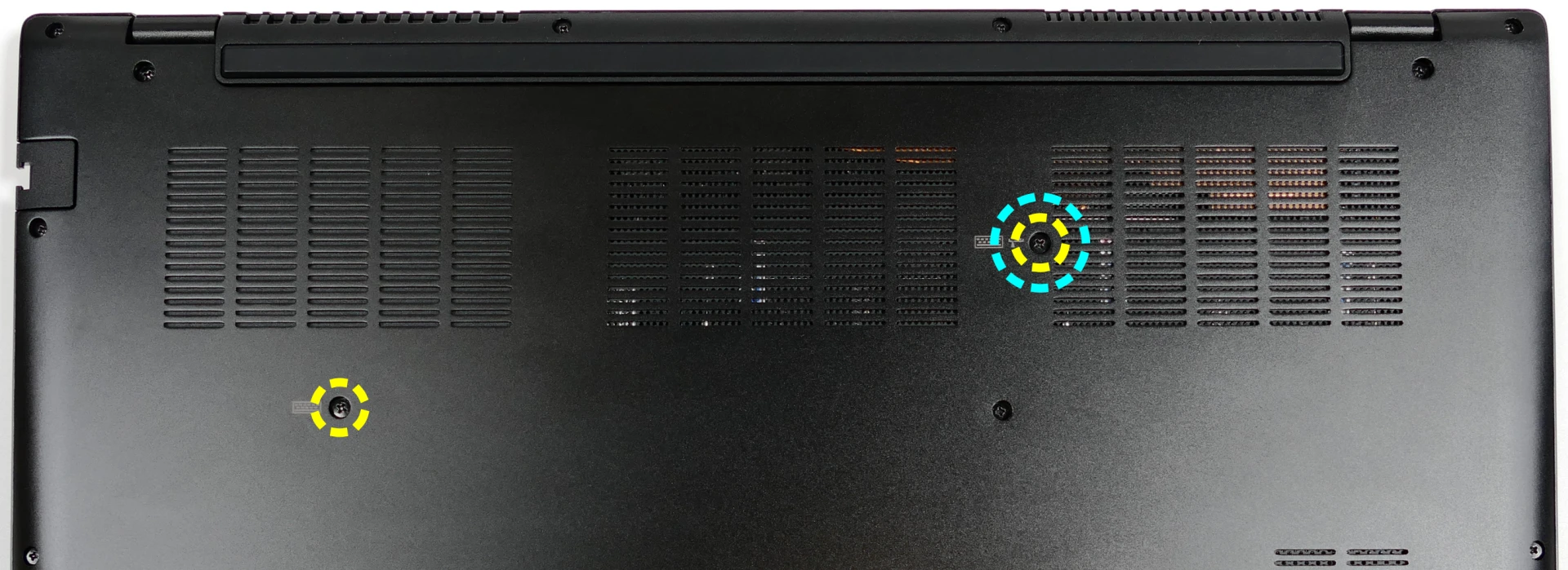
- Open the lid slightly and place the machine on its side.
- Push the screwdriver into the keyboard push point (highlighted cyan above) until the keyboard pops out.

- Set the machine back down and raise the keyboard away from the chassis. The larger ribbon cable is for the keyboard, while the smaller ribbon cable is for the keyboard backlight.

- Flip the black latches upwards to free the ribbon cables.
- Pull the ribbon cables out of the connectors.
- Remove the keyboard and replace it with the new one.
- Carefully slide both ribbon cables into their connectors.
- Flip the black latches back into place to secure the ribbon cables.
- Place the keyboard back into position, starting with the tabs on the bottom edge.
- Secure the rest of the keyboard by pressing down on each of its edges.
- Turn the machine lid-side down again and replace the two keyboard screws.
Replacing the battery:
The battery provides primary power whenever the system is unplugged.
CAUTION: Do not use metal tools to remove the battery. Do not touch the battery contacts with your hands or metal objects. If the battery is damaged during repairs, do not reinsert it into the laptop. Do not continue to use the computer if it contains a damaged battery. It is a potential fire hazard to operate a computer with a damaged battery. Keep children away from, and properly dispose of, the damaged battery. Always dispose of batteries carefully, by placing a piece of tape on the contact points. Take damaged batteries to an electronics recycling center and contact System76 to purchase a replacement. Batteries may explode or leak if exposed to fire, or if improperly handled or discarded. Only use batteries designed for your specific computer. This product contains a rechargeable battery. The battery is recyclable. At the end of its useful life, under various state and local laws, it may be illegal to dispose of this battery into the municipal waste stream. Check with your local solid waste officials for details in your area for recycling options or proper disposal.
The model number for the Darter Pro 8's battery is L140BAT-4, and the original part number is 6-87-L140S-72B01. Third-party battery sellers may list one or both of these numbers, and may offer other compatible part numbers with the same model number. You can also contact System76 to purchase a replacement battery.
Tools required: Cross-head (Phillips) screwdriver
Time estimate: 30 minutes
Difficulty: High ●
Steps to replace the battery:
- Follow the steps above to remove the bottom cover.
- Unplug the white connector that connects the battery to the motherboard.

- Remove the battery.
- The battery is secured to foam standoffs with double-sided tape.
- A flat plastic object (such as a credit card) can be used to separate the tape from the battery.
- If any tabs from the tape are visible around the perimeter of the battery, do not push them back under the battery.
- Hold the tabs down while inserting the plastic tool to separate the tape and foam from the battery.
- Alternatively, pull the tabs up with the battery to separate the tape and foam from the chassis.
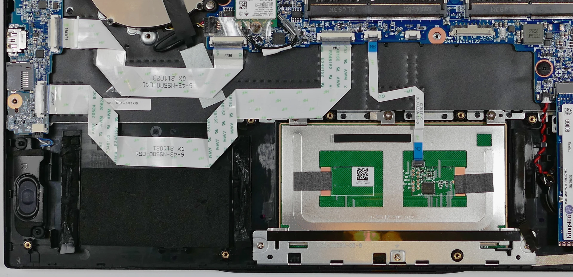
- Put the battery back (or put your new battery in its place) and plug it back into the motherboard.
Darter Pro (darp7)
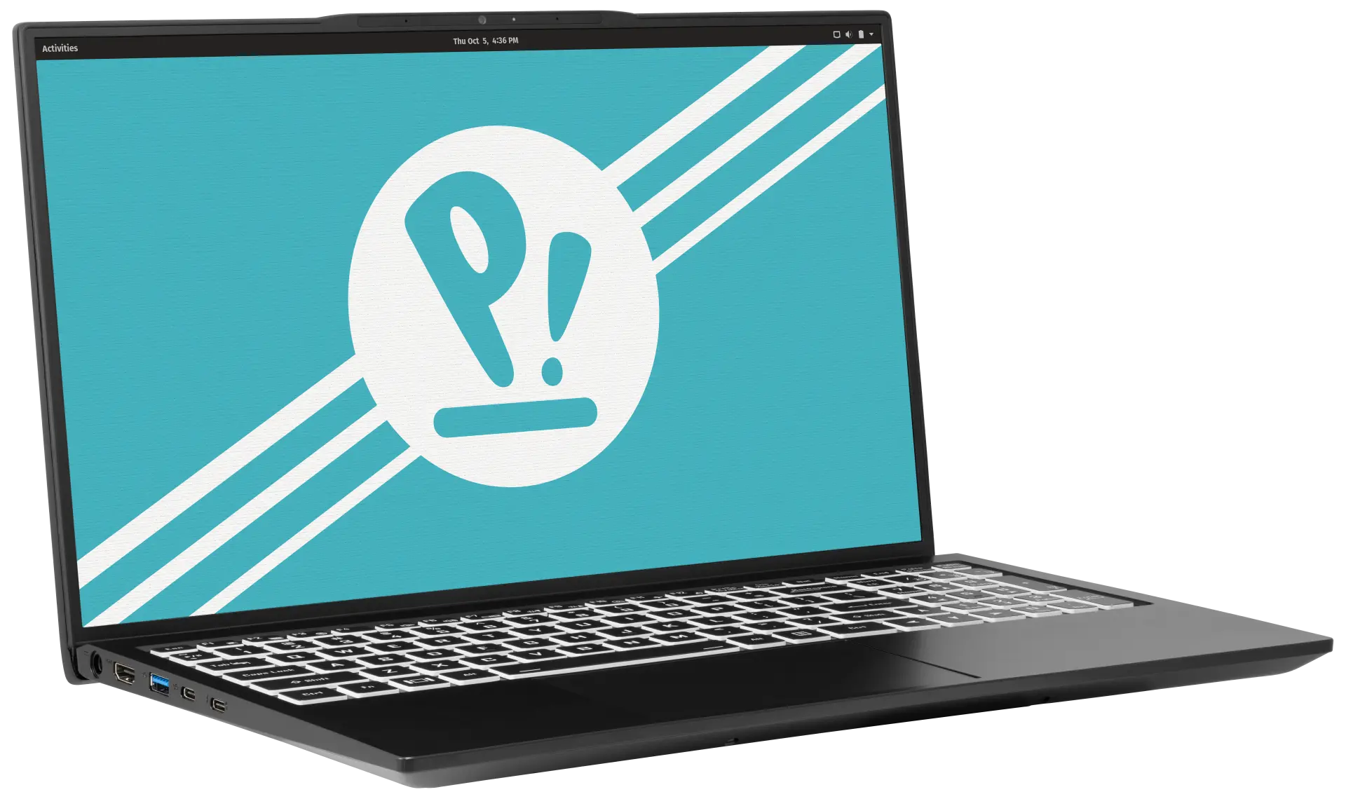
The System76 Darter Pro is a laptop with the following specifications:
- CPU
- Supports Intel 11th Generation (Tiger Lake) CPUs
- BIOS
- GD25B127D flash chip
- SOIC-8 form factor
- Programmed with System76 Open Firmware
- GD25B127D flash chip
- EC
- ITE IT5570E
- Programmed with System76 EC or non-open EC firmware
- Graphics
- GPU: Intel Iris Xe Graphics
- eDP display: 15.6" 1920x1080@60Hz LCD
- LCD panel options:
- AUO B156HAN02.5
- BOE NV156FHM-N4H
- or other equivalent
- LCD panel options:
- External video outputs:
- 1x HDMI
- 1x DisplayPort 1.4 over USB-C
- Memory
- Up to 64GB (2x32GB) dual-channel DDR4 SO-DIMMs @ 3200 MHz
- Networking
- Gigabit Ethernet
- M.2 PCIe/CNVi WiFi/Bluetooth
- Intel Wi-Fi 6 AX200/AX201
- Power
- 65W (19V, 3.42A) DC-in port
- Barrel size: 5.5mm (outer), 2.5mm (inner)
- Included AC adapter: Chicony A18-065N3A
- AC power cord type: IEC C5
- USB-C charging compatible with 65W+ charger
- 73Wh 4-cell Lithium-ion battery
- Model number: L140BAT-4
- 65W (19V, 3.42A) DC-in port
- Sound
- Internal speakers & microphone
- Combined headphone & microphone 3.5mm jack
- HDMI, USB-C DisplayPort audio
- Storage
- 1x M.2 (PCIe NVMe Gen 4)
- 1x M.2 (PCIe NVMe Gen 3 or SATA III)
- MicroSD card reader
- USB
- 1x USB Type-C with Thunderbolt 4
- Supports DisplayPort over USB-C
- Supports USB-C charging (USB-PD)
- 1x USB 3.2 (Gen 2) Type-C
- 1x USB 3.2 (Gen 2) Type-A
- 1x USB 2.0 Type-A
- 1x USB Type-C with Thunderbolt 4
- Dimensions
- 1.99cm x 35.7cm x 22.05cm, 1.74kg
Darter Pro (External Overview)
Left side overview:

Right side overview:

Front side overview:

Back side overview:

LED indicators:
| Icon | Color | Description |
|---|---|---|
 | Orange | Powered off, DC power plugged in |
| Green | Powered on | |
| Blinking green | Sleeping (suspended) | |
 | Orange | Battery charging |
| Green | Battery fully charged |
Materials:
| Part | Material |
|---|---|
| LCD back cover (lid) | Magnesium-aluminum alloy |
| LCD front cover (bezel) | Plastic |
| Top case (palm rests/port covers) | Plastic |
| Bottom panel | Magnesium-aluminum alloy |
Keyboard shortcuts:
| Key | Shortcut | Action |
|---|---|---|
 | Fn+F1 | Toggle trackpad |
 | Fn+F2 | Toggle built-in LCD |
 | Fn+F3 | Mute |
 | Fn+F5 | Volume down |
 | Fn+F6 | Volume up |
 | Fn+F7 | Toggle displays |
 | Fn+F8 | Screen brightness down |
 | Fn+F9 | Screen brightness up |
 | Fn+F10 | Toggle webcam |
 | Fn+F11 | Toggle airplane mode |
 | Fn+F12 | Suspend |
 | Fn+` | Play/Pause |
 | Fn+* | Toggle keyboard backlight |
| / | Fn+/ | Cycle keyboard color |
| - | Fn+- | Decrease keyboard brightness |
| + | Fn++ | Increase keyboard brightness |
Darter Pro (Internal Overview)
Bottom components and connectors:

- RAM slots are highlighted in purple
- Wireless card is highlighted in yellow
- Fan/heatsink module is highlighted in navy
- Fan connector is highlighted in white
- Webcam/microphone connector is highlighted in orange
- M.2 SSDs are highlighted in dark green
- CMOS battery connector is highlighted in pink
- Main battery connector is highlighted in cyan
- LCD panel connector is highlighted in light green
- Speaker connectors are highlighted in brown
- Touchpad connector is highlighted in light red
- Lid switch/sensor connector is highlighted in olive
- BIOS flash chip (U12) is highlighted in black
Under-keyboard components and connectors:

- Keyboard connector is highlighted in red
- Keyboard backlight connector is highlighted in yellow
- Lid switch/sensor to motherboard connector is highlighted in cyan
Darter Pro (Parts & Repairs)
Many components in your Darter Pro can be upgraded or replaced as necessary. Follow these step-by-step guides for instructions:
- Removing the bottom cover
- Replacing the RAM
- Replacing an M.2/NVMe SSD
- Replacing the WiFi/Bluetooth module
- Replacing the CMOS battery
- Replacing the fans/heatsink/thermal paste
- Replacing the keyboard
- Replacing the battery
Removing the bottom cover:
Removing the cover is required to access the internal components. Prior to removing the cover, ensure the AC power is unplugged and all peripherals (including SD cards and USB drives) are unplugged or removed from the system.
Tools required: Cross-head (Phillips) screwdriver
Time estimate: 7 minutes
Difficulty: Easy ●
Steps to remove the bottom cover:
- Place the machine lid-side down.
- Use a soft surface (such as a towel) to avoid scratches.
- Remove the 16 bottom panel screws:
- 12 perimeter screws (thin), highlighted green below.
- 2 keyboard screws (thicker), highlighted yellow.
- 2 inner hinge screws (thickest), highlighted red.
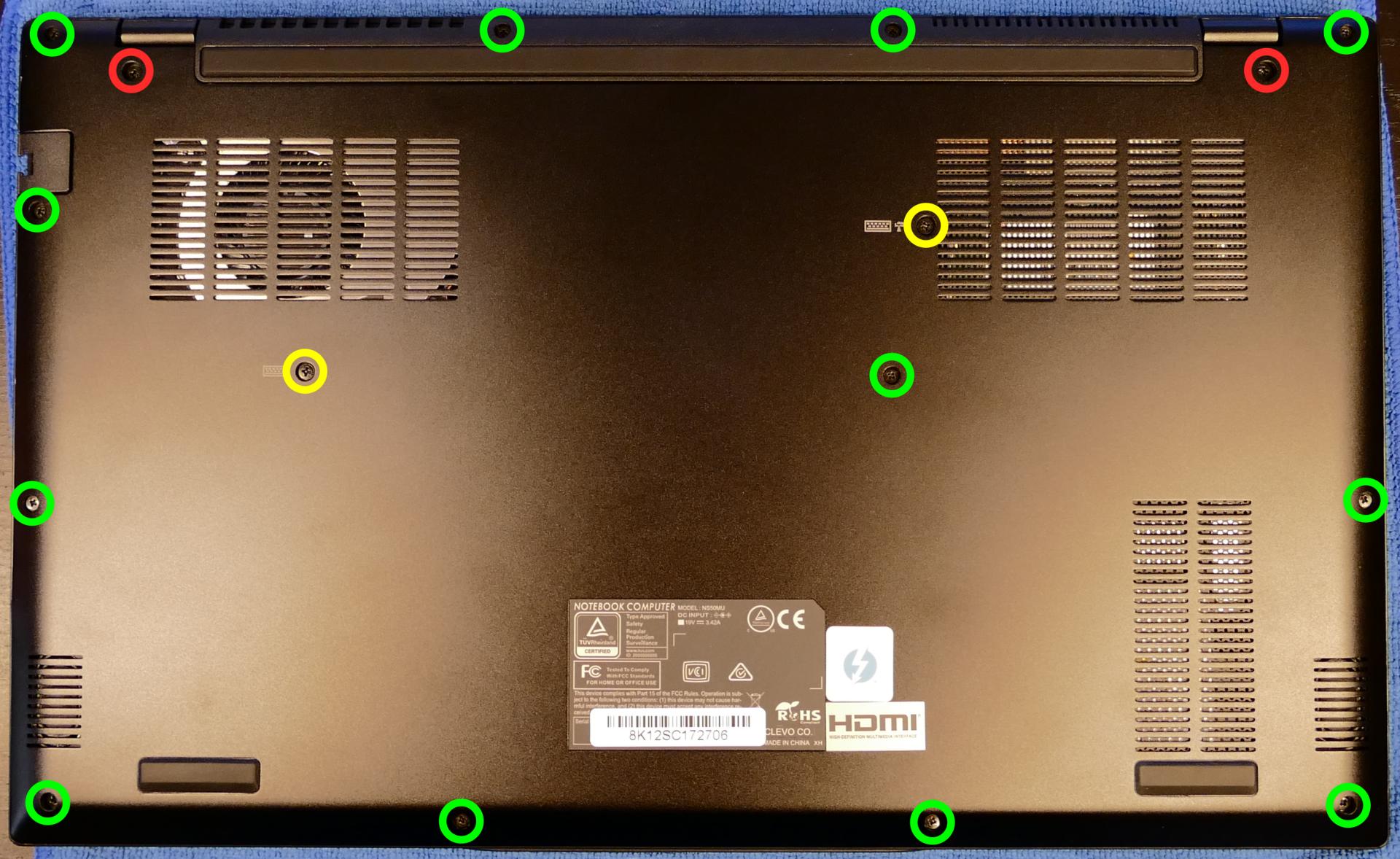
- Pull the bottom panel off, starting from the hinges in the back.
Replacing the RAM:
The Darter Pro 7 supports up to 64GB (2x32GB) of DDR4 SO-DIMMs running at 3200MHz. If you've purchased new RAM, need to replace your RAM, or are reseating your RAM, follow these steps.
Tools required: Cross-head (Phillips) screwdriver
Time estimate: 10 minutes
Difficulty: Easy ●
Steps to replace the RAM:
- Follow the steps above to remove the bottom cover.
- Press the small tabs on both sides of the RAM simultaneously. The RAM should spring up to an angle.

- Remove the RAM from the slot.
- Insert the new RAM (or reseat the existing RAM) by placing it in the keyed slot and pressing down until it clicks into place.
Replacing an M.2/NVMe SSD:
This model supports two M.2 SSDs. Both slots are size 2280. SSD-1 supports PCIe NVMe Gen 3 or SATA III, while SSD-2 supports PCIe NVMe Gen 4.
Tools required: Cross-head (Phillips) screwdriver
Time estimate: 10 minutes
Difficulty: Easy ●
Steps to replace the M.2 drive:
- Follow the steps above to remove the bottom cover.
- Unscrew the retainer screw opposite the M.2 slot.
- SSD-1 is closest to the battery (pictured on the left.)
- SSD-2 is closest to the outer edge of the machine (on the right.)

- Remove the existing M.2 drive by pulling it out of the slot.
- Insert the new M.2 drive into the slot and hold it in place.
- Replace the retainer screw.
- If a square brace was present on the old drive, transfer it to the new drive.
Replacing the wireless card:
Your Darter Pro's WiFi and Bluetooth are both handled by the same module. It is a standard M.2 2230 slot with PCIe and USB interfaces (E-key).
Tools required: Cross-head (Phillips) screwdriver
Time estimate: 12 minutes
Difficulty: Medium ●
Steps to replace the WiFi/Bluetooth module:
- Follow the steps above to remove the bottom cover.
- Locate the wireless module. Remove any clear tape that is securing the wires.

- Gently remove the two antennas (highlighted red above) by pulling them up and away from the wireless card.
- Remove the retaining screw opposite the M.2 slot, highlighted yellow above.
- The wireless card will pop up at an angle. Remove the card from the M.2 slot.
- Insert the new wireless card into the M.2 slot at an angle.
- Replace the retaining screw.
- Attach the two antennas by aligning the circular fittings and pressing onto the wireless card. The connectors will snap into place. Use caution when attaching the connectors; the pins can bend, break, or snap.
Replacing the CMOS battery:
The CMOS battery supplies power to the system's CMOS chip. UEFI settings and the computer's hardware clock are stored on the CMOS. If your system doesn't boot, you can reset the CMOS to force a low-level hardware reset. If your clock is constantly resetting, it's likely your CMOS battery needs to be replaced.
Warning (ingestion hazard): Keep batteries out of reach of children. Death or serious injury can occur if ingested. If a battery is suspected to be swallowed or inserted inside any part of the body, seek immediate medical attention. In the US, you can also call the National Battery Ingestion Hotline for guidance: 1 (800) 498-8666
Tools required: Cross-head (Phillips) screwdriver
Time estimate: 12 minutes
Difficulty: Easy ●
Steps to replace the CMOS battery:
- Follow the steps above to remove the bottom cover.
- Unplug the white connector attaching the CMOS battery to the motherboard (highlighted green below.)

- If you are replacing the CMOS battery, remove SSD-1 to expose the CMOS battery, then pull it away from the adhesive holding it to the case.
- To clear the CMOS, disconnect the main battery, open the lid of the machine, and hold down the power button for at least 15 seconds to discharge any residual energy in the system.
- Re-connect the CMOS battery and the main battery, and replace the SSD and bottom panel.
- Power up the machine. The system may power itself off and on after initial boot; this is normal behavior when the CMOS has been reset.
Replacing the cooling system:
The Darter Pro 7 has a single fan and heatsink to cool the CPU. The fan and heatsink are a single part (they should not be replaced separately from one another.)
If the fan becomes noisy and cleaning it out doesn't fix the issue, you may need a new fan. Contact Support to start a warranty claim or parts purchase.
Depending on your climate and the age of the machine, it may be necessary to apply new thermal paste between the CPU and the heatsink. Thermal paste helps facilitate effective heat transfer between the CPU and the cooling equipment. These instructions can also be used in the unlikely event your heatsink needs replacing.
Tools required: Cross-head (Phillips) screwdriver, thermal paste
Time estimate: 20 minutes
Difficulty: High ●
Steps to replace the fan/heatsink/thermal paste:
- Follow the steps above to remove the bottom cover.
- Peel back the black tape holding the fan to the chassis, and remove any clear tape that is securing the wires.
- Unplug the black fan connector.
- Remove the seven heatsink/fan screws in order, starting with #1, then #2, and so on until #7.

- Remove the fan and heatsink from the system, being careful not to bend the heatsink pipe. It may take some pressure to break the seal of the thermal paste.
- Using a paper towel, remove the existing thermal paste. You may also use a small amount of rubbing alcohol if the old paste is dried or difficult to remove.

- After cleaning the CPU and heatsink, apply a small line of thermal paste directly onto the CPU chip.

- Carefully replace the heatsink.
- Replace the seven heatsink/fan screws in order, starting with #1, then #2, and so on until #7.
Replacing the keyboard:
The keyboard can be replaced using the instructions below.
Tools required: Cross-head (Phillips) screwdriver
Time estimate: 5 minutes
Difficulty: Easy ●
Steps to replace the keyboard:
- Place the machine lid-side down.
- Use a soft surface (such as a towel) to avoid scratches.
- Remove the two keyboard screws (highlighted yellow below).

- Open the lid slightly and place the machine on its side.
- Push the screwdriver into the keyboard push point (highlighted cyan above) until the keyboard pops out.

- Set the machine back down and raise the keyboard away from the chassis. The larger ribbon cable is for the keyboard, while the smaller ribbon cable is for the keyboard backlight.

- Flip the black latches upwards to free the ribbon cables.
- Pull the ribbon cables out of the connectors.
- Remove the keyboard and replace it with the new one.
- Carefully slide both ribbon cables into their connectors.
- Flip the black latches back into place to secure the ribbon cables.
- Place the keyboard back into position, starting with the tabs on the bottom edge.
- Secure the rest of the keyboard by pressing down on each of its edges.
- Turn the machine lid-side down again and replace the two keyboard screws.
Replacing the battery:
The battery provides primary power whenever the system is unplugged.
CAUTION: Do not use metal tools to remove the battery. Do not touch the battery contacts with your hands or metal objects. If the battery is damaged during repairs, do not reinsert it into the laptop. Do not continue to use the computer if it contains a damaged battery. It is a potential fire hazard to operate a computer with a damaged battery. Keep children away from, and properly dispose of, the damaged battery. Always dispose of batteries carefully, by placing a piece of tape on the contact points. Take damaged batteries to an electronics recycling center and contact System76 to purchase a replacement. Batteries may explode or leak if exposed to fire, or if improperly handled or discarded. Only use batteries designed for your specific computer. This product contains a rechargeable battery. The battery is recyclable. At the end of its useful life, under various state and local laws, it may be illegal to dispose of this battery into the municipal waste stream. Check with your local solid waste officials for details in your area for recycling options or proper disposal.
The model number for the Darter Pro 7's battery is L140BAT-4, and the original part number is 6-87-L140S-72B01. Third-party battery sellers may list one or both of these numbers, and may offer other compatible part numbers with the same model number. You can also contact System76 to purchase a replacement battery.
Tools required: Cross-head (Phillips) screwdriver
Time estimate: 20 minutes
Difficulty: High ●
Steps to replace the battery:
- Follow the steps above to remove the bottom cover.
- Unplug the white connector that connects the battery to the motherboard.

- Remove the battery.
- The battery is secured to foam standoffs with double-sided tape.
- A flat plastic object (such as a credit card) can be used to separate the tape from the battery.
- If any tabs from the tape are visible around the perimeter of the battery, hold them down while inserting the plastic tool so they don't get pushed back under the battery.
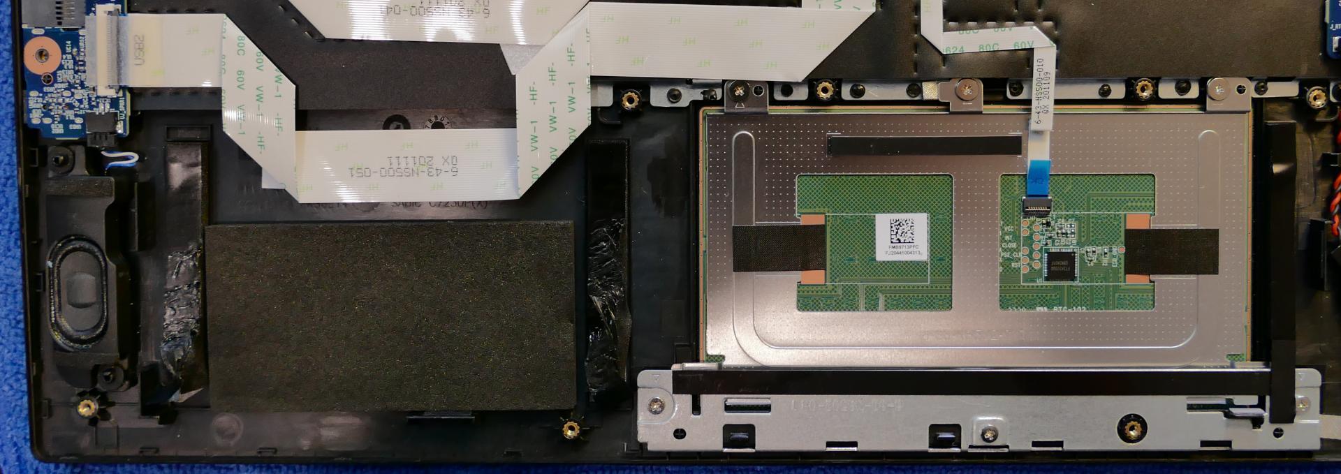
- Put the battery back (or put your new battery in its place) and plug it back into the motherboard.
Darter Pro (darp6)
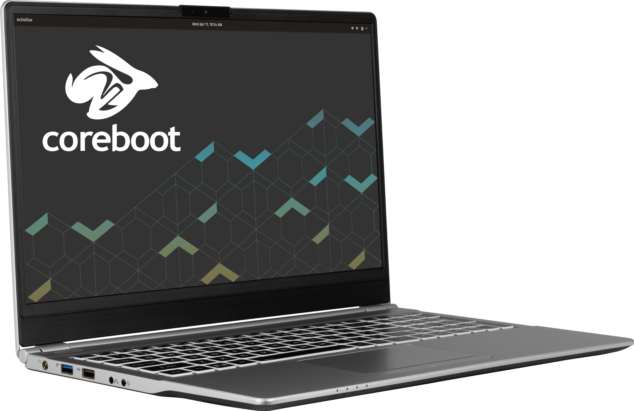
The System76 Darter Pro is a laptop with the following specifications:
- CPU
- Supports Intel 10th Generation (Comet Lake-U) CPUs
- BIOS
- GD25B127D flash chip
- SOIC-8 form factor
- Programmed with System76 Open Firmware
- GD25B127D flash chip
- EC
- ITE IT8587E
- Programmed with System76 EC or non-open EC firmware
- Graphics
- GPU: Intel UHD Graphics 620
- eDP display: 15.6" 1920x1080@60Hz LCD
- LCD panel: LG LP156WFC-SPD3 (or equivalent)
- External video outputs:
- 1x HDMI
- 1x Mini DisplayPort 1.2
- 1x DisplayPort 1.3 over USB-C
- Memory
- Up to 64GB (2x32GB) dual-channel DDR4 SO-DIMMs @ 2666 MHz
- Networking
- Gigabit Ethernet
- M.2 PCIe/CNVi WiFi/Bluetooth options:
- Intel Wi-Fi 6 AX200/AX201
- Intel Wireless-AC 9560
- Power
- 65W (19V, 3.42A) DC-in port
- Barrel size: 5.5mm (outer), 2.5mm (inner)
- Included AC adapter: Chicony A12-065N2A
- AC power cord type: IEC C5
- 54.5Wh 4-cell Lithium-Ion battery
- Model number: N150BAT-4
- 65W (19V, 3.42A) DC-in port
- Sound
- Internal speakers & microphone
- Combined headphone & microphone 3.5mm jack
- Combined microphone & S/PDIF (optical) 3.5mm jack
- HDMI, Mini DisplayPort, USB-C DisplayPort audio
- Storage
- 1x M.2 (PCIe NVMe or SATA)
- SD card reader
- USB
- 2x USB 3.0 Type-A
- 1x USB 2.0 Type-A
- 1x USB Type-C with Thunderbolt 3
- Dimensions
- 1.98cm x 36.04cm x 24.46cm, 1.6kg
Darter Pro (External Overview)
Left side overview:
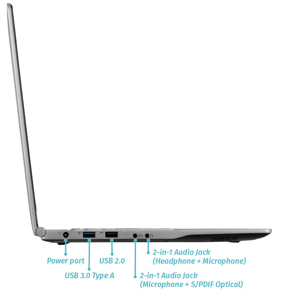
Right side overview:
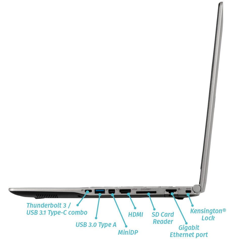
Front side overview:

Back side overview:

Keyboard Shortcuts
The Darter Pro has the following actions available using the Fn and Function keys:
| Key | Shortcut | Action |
|---|---|---|
 | Fn+F1 | Toggle trackpad |
 | Fn+F2 | Toggle built-in LCD |
 | Fn+F3 | Mute |
 | Fn+F5 | Volume down |
 | Fn+F6 | Volume up |
 | Fn+F7 | Toggle displays |
 | Fn+F8 | Screen brightness down |
 | Fn+F9 | Screen brightness up |
 | Fn+F10 | Toggle webcam |
 | Fn+F11 | Toggle airplane mode |
 | Fn+F12 | Suspend |
 | Fn+` | Play/Pause |
 | Fn+* | Toggle keyboard backlight |
| / | Fn+/ | Cycle keyboard color |
| - | Fn+- | Decrease keyboard brightness |
| + | Fn++ | Increase keyboard brightness |
LED indicators
The Darter Pro has the following LED indicators:
| Icon | Color | Description |
|---|---|---|
 | Orange | Powered off, DC power plugged in |
| Green | Powered on | |
| Blinking green | Sleeping (suspended) | |
 | Orange | Battery charging |
| Green | Battery fully charged | |
| Blinking orange | Battery critically low | |
 | Green | Airplane mode is on (WiFi/Bluetooth disabled) |
 | Green | Storage drive activity |
Darter Pro (Internal Overview)
Bottom components and connectors:

- RAM slots are highlighted in dark green
- M.2 SSD is highlighted in purple
- Wireless card is highlighted in yellow
- CMOS battery connector is highlighted in pink
- CMOS battery is highlighted in white
- Fan/heatsink module is highlighted in navy
- Fan connector is highlighted in light red
- Webcam/microphone connector is highlighted in orange
- LCD panel connector is highlighted in light green
- Main battery connector is highlighted in cyan
- Main battery is highlighted in brown
- Speaker connectors are highlighted in maroon
- Speakers are highlighted in olive
- Touchpad connector is underneath the battery, highlighted in dashed red
- Touchpad button connector is highlighted in dashed green
- Front LED connector is highlighted in dashed yellow
- BIOS flash chip (U26) is highlighted in black
Under-keyboard components and connectors:

- Keyboard connector is highlighted in cyan
- Keyboard backlight connector is highlighted in green
- Power button/LED connector is highlighted in red
- Left-side USB connector is highlighted in yellow
- Bottom panel screws are highlighted in pink
Darter Pro (Parts & Repairs)
Many components in your Darter Pro can be upgraded or replaced as necessary. Follow these step-by-step guides for instructions:
- Replacing the keyboard
- Removing the bottom cover
- Removing the battery
- Replacing the RAM
- Replacing an M.2/NVMe SSD
- Replacing the WiFi/Bluetooth module
- Replacing the CMOS battery
- Replacing the fans/heatsink/thermal paste
Replacing the keyboard:
The keyboard can be replaced using the instructions below. Removing the keyboard is required for removing the bottom panel.
Tools required: Cross-head (Phillips) screwdriver
Time estimate: 5 minutes
Difficulty: Easy ●
Steps to replace the keyboard:
- Place the machine lid-side down.
- Use a soft surface (such as a towel) to avoid scratches.
- Remove the two keyboard screws (highlighted red below).

- Open the lid slightly and place the machine on its side.
- Push the screwdriver into the keyboard push point (highlighted cyan above) until the keyboard pops out.

- Set the machine back down and raise the keyboard away from the chassis. The larger ribbon cable is for the keyboard, while the smaller ribbon cable is for the keyboard backlight.

Note: Unplugging the ribbon cables is not required to remove the bottom cover.
- Flip the black latches upwards to free the ribbon cables.
- Pull the ribbon cables out of the connectors.
- Remove the keyboard and replace it with the new one.
- Carefully slide both ribbon cables into their connectors.
- Flip the black latches back into place to secure the ribbon cables.
- Place the keyboard back into position, starting with the tabs on the bottom edge.
- Secure the rest of the keyboard by pressing down on each of its edges.
- Turn the machine lid-side down again and replace the two keyboard screws.
Removing the bottom cover:
Removing the cover is required to access the internal components. Prior to removing the cover, ensure the AC power is unplugged and all peripherals (including SD cards and USB drives) are unplugged or removed from the system.
Tools required: Cross-head (Phillips) screwdriver
Time estimate: 7 minutes
Difficulty: Easy ●
Steps to remove the bottom cover:
- Place the machine lid-side down.
- Use a soft surface (such as a towel) to avoid scratches.
- Remove the 12 bottom panel screws.

- Follow the steps above to remove the keyboard.
- Remove the three under-keyboard screws holding the bottom panel in place from above, highlighted cyan below.

- Lift the bottom panel off, starting from the hinges in the back.
Removing the battery:
The battery provides primary power whenever the system is unplugged.
The model number for the Darter Pro 6's battery is N150BAT-4, and the original part number is 6-87-N15Zs-51E01. Third-party battery sellers may list one or both of these numbers, and may offer other compatible part numbers with the same model number. You can also contact System76 to purchase a replacement battery.
Tools required: Cross-head (Phillips) screwdriver
Time estimate: 10 minutes
Difficulty: Easy ●
Steps to remove the battery:
- Follow the steps above to remove the keyboard and remove the bottom cover.
- Remove the seven battery screws, highlighted red below.

- Unplug the battery connector (highlighted green above) and lift the battery out of the chassis.
Replacing the RAM:
The Darter Pro 6 supports up to 64GB (2x32GB) of DDR4 SO-DIMMs running at 2666MHz. If you've purchased new RAM, need to replace your RAM, or are reseating your RAM, follow these steps.
Tools required: Cross-head (Phillips) screwdriver
Time estimate: 10 minutes
Difficulty: Easy ●
Steps to replace the RAM:
- Follow the steps above to remove the keyboard and remove the bottom cover.
- Press the small tabs on both sides of the RAM simultaneously. The RAM should spring up to an angle.

- Remove the RAM from the slot.
- Insert the new RAM (or reseat the existing RAM) by placing it in the keyed slot and pressing down until it clicks into place.
Replacing an M.2/NVMe SSD:
This model supports one M.2 SSD of size 2280, either SATA III or PCIe NVMe Generation 3.
Tools required: Cross-head (Phillips) screwdriver
Time estimate: 10 minutes
Difficulty: Easy ●
Steps to replace the M.2 drive:
- Follow the steps above to remove the keyboard and remove the bottom cover.
- Unscrew the retainer screw opposite the M.2 slot.

- Remove the existing M.2 drive by pulling it out of the slot.
- Insert the new M.2 drive into the slot and hold it in place.
- Replace the retainer screw.
- If a square brace was present on the old drive, transfer it to the new drive.
Replacing the wireless card:
Your Darter Pro's WiFi and Bluetooth are both handled by the same module. It is a standard M.2 2230 slot with PCIe and USB interfaces (E-key).
Tools required: Cross-head (Phillips) screwdriver
Time estimate: 12 minutes
Difficulty: Medium ●
Steps to replace the WiFi/Bluetooth module:
- Follow the steps above to remove the keyboard and remove the bottom cover.
- Locate the wireless module. Remove any clear tape that is securing the wires.

- Gently remove the two antennas (highlighted red above) by pulling them up and away from the wireless card.
- Remove the retaining screw opposite the M.2 slot, highlighted green above.
- The wireless card will pop up at an angle. Remove the card from the M.2 slot.
- Insert the new wireless card into the M.2 slot at an angle.
- Replace the retaining screw.
- Attach the two antennas by aligning the circular fittings and pressing onto the wireless card. The connectors will snap into place. Use caution when attaching the connectors; the pins can bend, break, or snap.
Replacing the CMOS battery:
The CMOS battery supplies power to the system's CMOS chip. UEFI settings and the computer's hardware clock are stored on the CMOS. If your system doesn't boot, you can reset the CMOS to force a low-level hardware reset. If your clock is constantly resetting, it's likely your CMOS battery needs to be replaced.
Warning (ingestion hazard): Keep batteries out of reach of children. Death or serious injury can occur if ingested. If a battery is suspected to be swallowed or inserted inside any part of the body, seek immediate medical attention. In the US, you can also call the National Battery Ingestion Hotline for guidance: 1 (800) 498-8666
Tools required: Cross-head (Phillips) screwdriver
Time estimate: 10 minutes
Difficulty: Easy ●
Steps to replace the CMOS battery:
- Follow the steps above to remove the keyboard and remove the bottom cover.
- Unplug the white connector attaching the CMOS battery to the motherboard (highlighted green below.)

- If you are replacing the CMOS battery, pull it away from the adhesive holding it to the case.
- To clear the CMOS, disconnect the main battery, open the lid of the machine, and hold down the power button for at least 15 seconds to discharge any residual energy in the system.
- Re-connect the CMOS battery and the main battery, and replace the bottom panel and keyboard.
- Power up the machine. The system may power itself off and on after initial boot; this is normal behavior when the CMOS has been reset.
Replacing the cooling system:
The Darter Pro 6 has a single fan and heatsink to cool the CPU. The fan and heatsink can be removed or replaced separately from one another.
If the fan becomes noisy and cleaning it out doesn't fix the issue, you may need a new fan. Contact Support to start a warranty claim or parts purchase.
Depending on your climate and the age of the machine, it may be necessary to apply new thermal paste between the CPU and the heatsink. Thermal paste helps facilitate effective heat transfer between the CPU and the cooling equipment. These instructions can also be used in the unlikely event your heatsink needs replacing.
Tools required: Cross-head (Phillips) screwdriver, thermal paste
Time estimate: 20 minutes
Difficulty: High ●
Steps to replace the fan:
- Follow the steps above to remove the keyboard and remove the bottom cover.
- Remove the two fan screws, highlighted green below.

- Unplug the black fan connector, highlighted cyan above. Remove any clear tape that may be holding the wires in place.
- Remove the fan from the system.
Steps to replace the heatsink/thermal paste:
- Follow the steps above to remove the keyboard and remove the bottom cover.
- Remove the three heatsink screws (highlighted red above) in order, starting with #1, then #2, and finally #3.
- Remove the heatsink from the system, being careful not to bend the heatsink pipe. It may take some pressure to break the seal of the thermal paste.
- Using a paper towel, remove the existing thermal paste. You may also use a small amount of rubbing alcohol if the old paste is dried or difficult to remove.

- After cleaning the CPU and heatsink, apply a small line of thermal paste directly onto the CPU chip.

- Carefully replace the heatsink.
- Replace the three heatsink screws, starting with #1, then #2, and finally #3.
Eland 1U (elan1-r2)
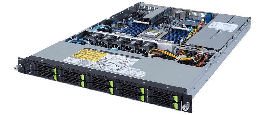
The System76 Eland 1U is a rack-mounted server. The R2 model code indicates the second revision based on an AMD platform. This model has the following specifications:
- Chassis
- CPU options
- Supports 1x AMD EPYC 7003-series processor
- Memory
- Up to 4096GB (16x256GB) ECC DDR4 @ 3200 MHz
- Storage
- 10x 2.5" SATA hot-swappable HDD/SSD bays
- Networking
- 2x 1GbE LAN ports (1 x Intel® I350-AM2)
- 1x 1GbE management LAN
- Expansion
- 1x PCIe 4.0 x16
- Front I/O
- 1x USB 3.0
- 1x Power button with LED
- 1x ID button with LED
- 1x NMI button
- 1x Reset button
- 2x LAN activity LEDs
- 1x HDD activity LED
- 1x System status LED
- Back I/O
- 3x USB 3.0
- 1x VGA
- 1x COM
- 2x RJ45 (Ethernet)
- 1x Management LAN
- 1x ID button with LED
- Power Supply
- 2x 650W redundant 80+ Platinum PSUs
- AC Input: 100-240V 12-6A, 50-60Hz
- Dimensions
- 43.8cm × 66.0cm × 4.35cm
- Weight
- 20.32kg
Eland 1U (elan1-r1)
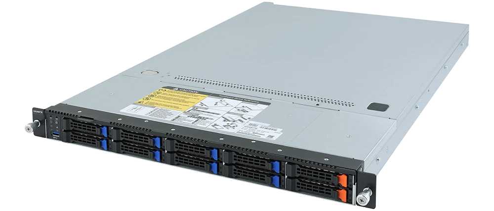
The System76 Eland 1U is a rack-mounted server. The R1 model code indicates the first revision based on an AMD platform. This model has the following specifications:
- Chassis
- CPU options
- Supports 1x AMD EPYC 7003-series processor
- Memory
- Up to 4096GB (16x256GB) ECC DDR4 @ 3200 MHz
- Storage
- 4x 3.5"/2.5" SATA hot-swappable HDD/SSD bays
- Networking
- 2x 1GbE LAN ports (1 x Intel® I350-AM2)
- 1x 1GbE management LAN
- Expansion
- 1x PCIe 4.0 x16
- Front I/O
- 2x USB 3.0
- 1x Power button with LED
- 1x ID button with LED
- 1x NMI button
- 1x Reset button
- 2x LAN activity LEDs
- 1x HDD activity LED
- 1x System status LED
- Back I/O
- 3x USB 3.0
- 1x VGA
- 1x COM
- 2x RJ45 (Ethernet)
- 1x Management LAN
- 1x ID button with LED
- Power Supply
- 2x 650W redundant 80+ Platinum PSUs
- AC Input: 100-240V 10-5A, 50-60Hz
- Dimensions
- 43.8cm × 66.0cm × 4.35cm
- Weight
- 17.24kg
Eland Pro 1U (elap1-r2)
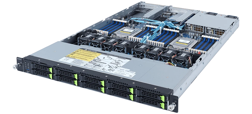
The System76 Eland Pro 1U is a rack-mounted server. The R2 model code indicates the second revision based on an AMD platform. This model has the following specifications:
- Chassis
- CPU options
- Supports 1x AMD EPYC 7003-series processor
- Memory
- Up to 8192GB (32x256GB) ECC DDR4 @ 3200 MHz
- Storage
- 10x 2.5" U.2 NVMe Gen 4 hot-swappable SSD bays
- Networking
- 2x 1GbE LAN ports (1 x Intel I350-AM2)
- 1x 1GbE management LAN
- Expansion
- 1x PCIe 4.0 x16
- Front I/O
- 1x USB 3.0
- 1x Power button with LED
- 1x ID button with LED
- 1x NMI button
- 1x Reset button
- 2x LAN activity LEDs
- 1x HDD activity LED
- 1x System status LED
- Back I/O
- 3x USB 3.0
- 1x VGA
- 2x RJ45 (Ethernet)
- 1x Management LAN
- 1x ID button with LED
- Power Supply
- 2x 1200W or 1600W redundant 80+ Platinum PSUs
- AC Input: 100-240V 12-7A, 50-60Hz
- Dimensions
- 43.8cm × 73.0cm × 4.35cm
- Weight
- 22kg
Eland Pro 1U (elap1-r1)
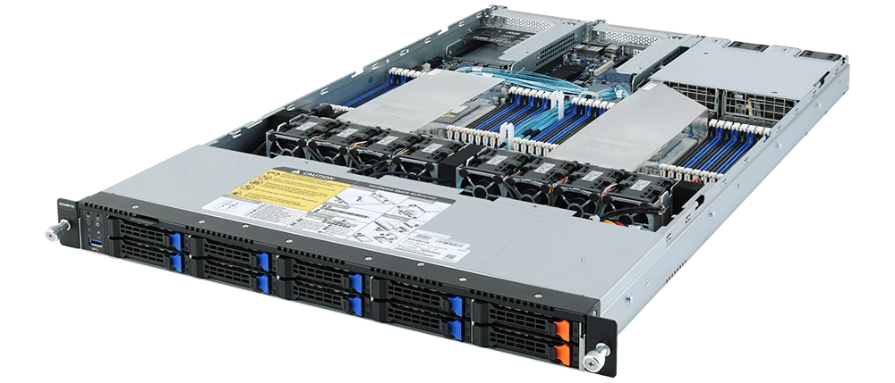
The System76 Eland Pro 1U is a rack-mounted server. The R1 model code indicates the first revision based on an AMD platform. This model has the following specifications:
- Chassis
- CPU options
- Supports 1x AMD EPYC 7003-series processor
- Memory
- Up to 8192GB (32x256GB) ECC DDR4 @ 3200 MHz
- Storage
- 8 x 2.5" SATA/SAS hot-swappable HDD/SSD bays
- 2 x 2.5" U.2 NVMe Gen 3 hot-swappable SSD bays
- Networking
- 2x 1GbE LAN ports (1 x Intel I350-AM2)
- 1x 1GbE management LAN
- Expansion
- 1x PCIe 4.0 x16
- Front I/O
- 1x USB 3.0
- 1x Power button with LED
- 1x ID button with LED
- 1x NMI button
- 1x Reset button
- 2x LAN activity LEDs
- 1x HDD activity LED
- 1x System status LED
- Back I/O
- 3x USB 3.0
- 1x VGA
- 2x RJ45 (Ethernet)
- 1x Management LAN
- 1x ID button with LED
- Power Supply
- 2 x 1200W redundant 80+ Platinum PSUs
- AC Input: 100-240V 12-7A, 50-60Hz
- Dimensions
- 43.8cm × 73.0cm × 4.35cm
- Weight
- 20.32kg
Eland Pro 2U (elap2-r2)
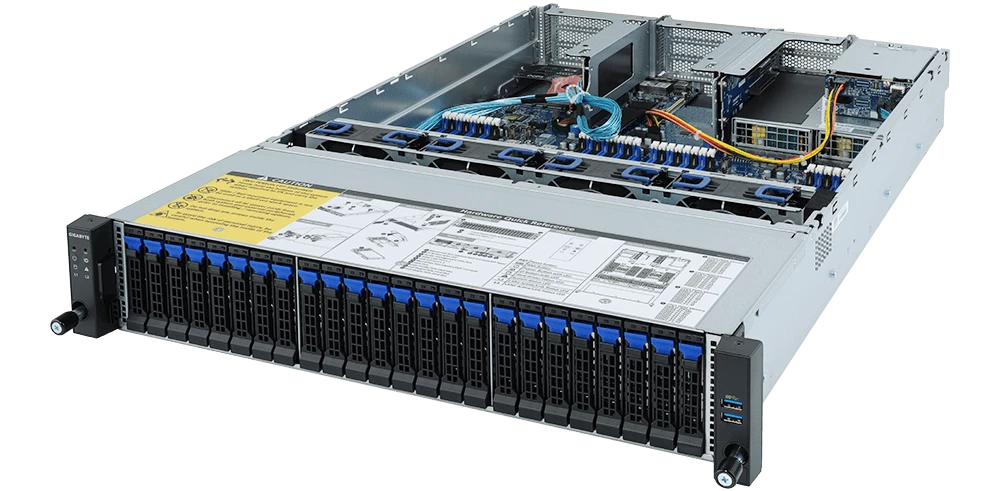
The System76 Eland Pro 2U is a rack-mounted server. The R2 model code indicates the second revision based on an AMD platform. This model has the following specifications:
- Chassis
- CPU options
- Supports 2x AMD EPYC 7003-series or 7002-series processors
- Memory
- Up to 8192GB (32x256GB) ECC DDR4 @ 3200 MHz
- Storage
- Front: 24x 2.5" SATA/SAS hot-swappable HDD/SSD bays
- Back: 2x 2.5" SATA/SAS hot-swappable HDD/SSD bays
- Internal: 1x M.2 PCIe NVMe Gen 3 x4 slot
- CPU TDP limited to 225W if M.2 slot is occupied
- Networking
- 2x 1GbE LAN ports (1 x Intel I350-AM2)
- 1x 1GbE management LAN
- Expansion
- Riser Card CRS2027 (CPU 1):
- 2x PCIe Gen 4 x8 (half-height, half-length)
- Riser Card CRS2033 (CPU 0):
- 1x PCIe Gen 4 x16 (full-height, half-length)
- 2x PCIe Gen 4 x8 (full-height, half-length)
- Riser Card CRS2033 (CPU 1):
- 1x PCIe Gen 4 x16 (full-height, half-length)
- 2x PCIe Gen 4 x8 (full-height, half-length)
- Riser Card CRS2027 (CPU 1):
- Front I/O
- 2x USB 3.0
- 1x Power button with LED
- 1x ID button with LED
- 1x Reset button
- 1x NMI button
- 1x System status LED
- 1x HDD activity LED
- 2x LAN activity LEDs
- Back I/O
- 2x USB 3.0
- 1x VGA
- 2x RJ45 (Ethernet)
- 1x Management LAN
- 1x ID button with LED
- Power Supply
- 2x 1600W redundant 80+ Platinum PSUs
- AC Input: 100-240V 12-7A, 50-60Hz
- Dimensions
- 43.8cm × 73.0cm × 8.7cm
- Weight
- 25.5kg
Eland Pro 2U (elap2-r1)
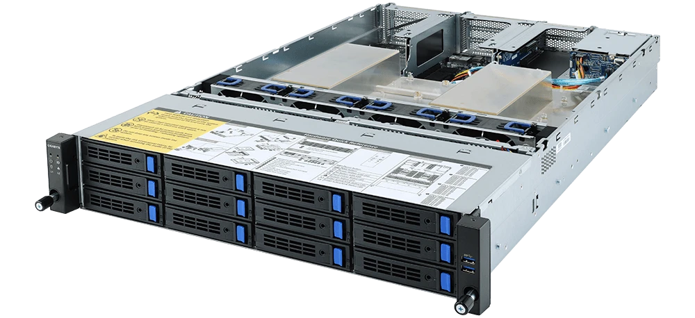
The System76 Eland Pro 2U is a rack-mounted server. The R1 model code indicates the first revision based on an AMD platform. This model has the following specifications:
- Chassis
- CPU options
- Supports 2x AMD EPYC 7003-series or 7002-series processors
- Memory
- Up to 8192GB (32x256GB) ECC DDR4 @ 3200 MHz
- Storage
- Front: 12x 3.5"/2.5" SATA/SAS hot-swappable HDD/SSD bays
- Back: 2x 2.5" SATA/SAS hot-swappable HDD/SSD bays
- Internal: 1x M.2 PCIe NVMe Gen 3 x4 slot
- CPU TDP limited to 225W if M.2 slot is occupied
- Networking
- 2x 1GbE LAN ports (1 x Intel I350-AM2)
- 1x 1GbE management LAN
- Expansion
- Riser Card CRS2027 (CPU 1):
- 2x PCIe Gen 4 x8 (half-height, half-length)
- Riser Card CRS2033 (CPU 0):
- 1x PCIe Gen 4 x16 (full-height, half-length)
- 2x PCIe Gen 4 x8 (full-height, half-length)
- Riser Card CRS2033 (CPU 1):
- 1x PCIe Gen 4 x16 (full-height, half-length)
- 2x PCIe Gen 4 x8 (full-height, half-length)
- Riser Card CRS2027 (CPU 1):
- Front I/O
- 2x USB 3.0
- 1x Power button with LED
- 1x ID button with LED
- 1x Reset button
- 1x NMI button
- 1x System status LED
- 1x HDD activity LED
- 2x LAN activity LEDs
- Back I/O
- 2x USB 3.0
- 1x VGA
- 2x RJ45 (Ethernet)
- 1x Management LAN
- 1x ID button with LED
- Power Supply
- 2x 1200W or 1600W redundant 80+ Platinum PSUs
- AC Input: 100-240V 12-7A, 50-60Hz
- Dimensions
- 43.8cm × 73.0cm × 8.7cm
- Weight
- 25.5kg
Galago Pro (galp6)
The System76 Galago Pro is a laptop with the following specifications:
- CPU
- Supports Intel 12th Generation (Alder Lake-U) CPUs
- BIOS
- Macronix MX25L25673GZ4I-08G flash chip
- WSON-8 form factor
- Programmed with System76 Open Firmware
- Macronix MX25L25673GZ4I-08G flash chip
- EC
- ITE IT5570E
- Programmed with System76 EC
- Graphics
- GPU options:
- Intel Iris Xe Graphics
- eDP display: 14.1" 1920x1080@60Hz LCD
- LCD panel: Panda LM140LF2L02 (or equivalent)
- External video outputs:
- 1x HDMI 2.1
- 1x DisplayPort 1.4 over USB-C
- GPU options:
- Memory
- Up to 64GB (2x32GB) dual-channel DDR4 SO-DIMMs @ 3200 MHz
- Networking
- Gigabit Ethernet
- M.2 PCIe/CNVi WiFi/Bluetooth
- Intel Wi-Fi 6 AX200/AX201
- Power
- 90W (19V, 4.74A) DC-in port
- Barrel size: 5.5mm (outer), 2.5mm (inner)
- Included AC adapter: Chicony A16-090P1A
- AC power cord type: IEC C5
- USB-C charging compatible with 90W+ charger
- 53Wh 4-cell Lithium-Ion battery
- Model number: NV40BAT-4-53
- 90W (19V, 4.74A) DC-in port
- Sound
- Internal speakers & microphone
- 3.5mm headphone/microphone combo jack
- HDMI, USB-C DisplayPort audio
- Storage
- 1x M.2 (PCIe NVMe Gen 4) SSD
- SD card reader
- USB
- 1x USB Type-C with Thunderbolt 4
- Supports DisplayPort over USB-C
- Supports USB-C charging (USB-PD)
- 1x USB 3.2 (Gen 2) Type-C
- 2x USB 3.2 (Gen 1) Type-A
- 1x USB Type-C with Thunderbolt 4
- Dimensions
- 32.49cm x 22.5cm x 1.82cm, 1.45kg
Galago Pro (External Overview)
Left side overview:

Right side overview:

Front side overview:

Back side overview:

Keyboard & touchpad overview:

Materials:
| Part | Material |
|---|---|
| LCD back cover (lid) | Aluminum |
| LCD front cover (bezel) | Plastic |
| Top case (palm rests/port covers) | Plastic |
| Bottom panel | Plastic |
LED indicators
The Galago Pro has the following LED indicators:
| Icon | Color | Description |
|---|---|---|
 | Orange | Powered off, DC power plugged in |
| Green | Powered on | |
| Blinking green | Sleeping (suspended) | |
 | Orange | Battery charging |
| Green | Battery fully charged | |
| Blinking orange | Battery critically low |
Keyboard Shortcuts
The Galago Pro has the following actions available using the Fn and Function keys:
| Key | Shortcut | Action |
|---|---|---|
 | Fn+F1 | Toggle trackpad |
 | Fn+F2 | Toggle built-in LCD |
 | Fn+F3 | Mute |
 | Fn+F4 | Cycle keyboard backlight brightness |
 | Fn+F5 | Volume down |
 | Fn+F6 | Volume up |
 | Fn+F7 | Toggle displays |
 | Fn+F8 | Screen brightness down |
 | Fn+F9 | Screen brightness up |
 | Fn+F10 | Toggle webcam |
 | Fn+F11 | Toggle airplane mode |
 | Fn+F12 | Suspend |
 | Fn+` | Play/Pause |
| 1 | Fn+1 | Toggle fan between max/automatic |
Galago Pro (Internal Overview)
Bottom components and connectors:

- RAM slots are highlighted in purple
- M.2 SSD is highlighted in maroon
- Wireless card is highlighted in yellow
- CMOS battery connector is highlighted in pink
- Webcam/microphone connector is highlighted in cyan
- BIOS flash chip (U43) is highlighted in black
- Fan connectors are highlighted in red
- Speaker connectors are highlighted in dark green
- Main battery connector is highlighted in orange
- Touchpad connector is highlighted in white
- LCD panel connector is highlighted in light green
Under-keyboard components and connectors:

- Keyboard connector is highlighted in green
- Keyboard backlight connector is highlighted in red
- EC chip is highlighted in cyan
- ITE IT5570E-128 2205-EXA 1A1RB
Galago Pro (Parts & Repairs)
Many components in your Galago Pro can be upgraded or replaced as necessary. Follow these step-by-step guides for instructions:
- Removing the bottom cover
- Removing the battery
- Replacing the RAM
- Replacing an M.2/NVMe SSD
- Replacing the WiFi/Bluetooth module
- Replacing the CMOS battery
- Replacing the speakers
- Replacing the fans/heatsink/thermal paste
- Replacing the keyboard
Removing the bottom cover:
Removing the cover is required to access the internal components. Prior to removing the cover, ensure the AC power is unplugged and all peripherals (including SD cards and USB drives) are unplugged or removed from the system.
Tools required: Cross-head (Phillips) screwdriver
Time estimate: 5 minutes
Difficulty: Easy ●
Steps to remove the bottom cover:
- Place the machine lid-side down.
- Use a soft surface (such as a towel) to avoid scratches.
- Remove the 14 bottom panel screws.
- The two hinge corner screws (highlighted red below) are slightly thicker than the rest.

- Pull the bottom panel off, starting from the hinges and vents in the back.
Removing the battery:
The battery provides primary power whenever the system is unplugged.
The model number for the Galago Pro 6's battery is NV40BAT-4-53, and the original part number is 6-87-NV4PS-54B01. Third-party battery sellers may list one or both of these numbers, and may offer other compatible part numbers with the same model number. You can also contact System76 to purchase a replacement battery.
Tools required: Cross-head (Phillips) screwdriver
Time estimate: 10 minutes
Difficulty: Easy ●
Steps to remove the battery:
- Follow the steps above to remove the bottom cover.
- Remove the five battery screws, highlighted yellow below.

- Unplug the battery connector (highlighted cyan above) and lift the battery out of the chassis.
Replacing the RAM:
The Galago Pro 6 supports up to 64GB (2x32GB) of DDR4 SO-DIMMs running at 3200MHz. If you've purchased new RAM, need to replace your RAM, or are reseating your RAM, follow these steps.
Tools required: Cross-head (Phillips) screwdriver
Time estimate: 10 minutes
Difficulty: Easy ●
Steps to replace the RAM:
- Follow the steps above to remove the bottom cover.
- Press the small tabs on both sides of the RAM simultaneously. The RAM should spring up to an angle.

- Remove the RAM from the slot.
- Insert the new RAM (or reseat the existing RAM) by placing it in the keyed slot and pressing down until it clicks into place.
Replacing an M.2/NVMe SSD:
This model supports one M.2 SSD of size 2280, PCIe NVMe Generation 4 (or Generation 3).
Tools required: Cross-head (Phillips) screwdriver
Time estimate: 10 minutes
Difficulty: Easy ●
Steps to replace the M.2 drive:
- Follow the steps above to remove the bottom cover.
- Unscrew the retainer screw opposite the M.2 slot.

- Remove the existing M.2 drive by pulling it out of the slot.
- Insert the new M.2 drive into the slot and hold it in place.
- Replace the retainer screw.
Replacing the wireless card:
Your Galago Pro's WiFi and Bluetooth are both handled by the same module. It is a standard M.2 2230 slot with PCIe and USB interfaces (E-key).
Tools required: Cross-head (Phillips) screwdriver
Time estimate: 12 minutes
Difficulty: Medium ●
Steps to replace the WiFi/Bluetooth module:
- Follow the steps above to remove the bottom cover.
- Locate the wireless module. Remove any clear tape that is securing the wires.

- Gently remove the two antennas (highlighted red above) by pulling them up and away from the wireless card.
- Remove the retaining screw opposite the M.2 slot, highlighted yellow above.
- The wireless card will pop up at an angle. Remove the card from the M.2 slot.
- Insert the new wireless card into the M.2 slot at an angle.
- Replace the retaining screw.
- Attach the two antennas by aligning the circular fittings and pressing onto the wireless card. The connectors will snap into place. Use caution when attaching the connectors; the pins can bend, break, or snap.
Replacing the CMOS battery:
The CMOS battery supplies power to the system's CMOS chip. UEFI settings and the computer's hardware clock are stored on the CMOS. If your system doesn't boot, you can reset the CMOS to force a low-level hardware reset. If your clock is constantly resetting, it's likely your CMOS battery needs to be replaced.
Warning (ingestion hazard): Keep batteries out of reach of children. Death or serious injury can occur if ingested. If a battery is suspected to be swallowed or inserted inside any part of the body, seek immediate medical attention. In the US, you can also call the National Battery Ingestion Hotline for guidance: 1 (800) 498-8666
Tools required: Cross-head (Phillips) screwdriver
Time estimate: 15 minutes
Difficulty: Medium ●
Steps to replace the CMOS battery:
- Follow the steps above to remove the bottom cover.
- Follow the steps above to remove the M.2 drive, then pull the battery away from the adhesive holding it to the case.
- If you are not replacing the CMOS battery, this step is optional, but will make it easier to unplug the CMOS battery connector.

- Unplug the white connector attaching the CMOS battery to the motherboard (highlighted green above.)
- To clear the CMOS, disconnect the main battery, open the lid of the machine, and hold down the power button for at least 15 seconds to discharge any residual energy in the system.
- Re-connect the CMOS battery and main battery, and replace the M.2 drive and bottom panel.
- Power up the machine. The system may power itself off and on after initial boot; this is normal behavior when the CMOS has been reset.
Replacing the speakers:
The system has two bottom-firing speakers, which can be removed and replaced individually.
Tools required: Cross-head (Phillips) screwdriver
Time estimate: 15 minutes
Difficulty: Easy ●
Steps to replace the speakers:
- Follow the steps above to remove the bottom cover. For the right speaker, also remove the battery and remove the SSD.
- Unscrew the speaker screws.
- Each speaker has two screws, which are set inside of rubber rings to reduce vibration.

- Disconnect the speaker wire from the motherboard and lift the speaker out of the machine.
- The speaker wire may be partially routed behind other components or tape; be careful when removing it.
- Place the new speaker in the machine, plug in the connector, replace the screws, and reinstall the SSD and battery (if necessary) and bottom panel.
Replacing the cooling system:
The Galago Pro 6 has a single heatsink with two fans for the CPU and integrated GPU. Both fans are separate from the heatsink and can be replaced independently.
If a fan becomes noisy and cleaning it out doesn't fix the issue, you may need a new fan. Contact support to start a warranty claim or parts purchase.
Depending on your climate and the age of the machine, it may be necessary to apply new thermal paste between the CPU and the heatsink. Thermal paste helps facilitate effective heat transfer between the CPU and the cooling equipment. These instructions can also be used in the unlikely event that your heatsink needs to be replaced.
Tools required: Cross-head (Phillips) screwdriver, thermal paste
Time estimate: 20 minutes
Difficulty: High ●
Steps to replace the fans:
- Follow the steps above to remove the bottom cover.
- Remove any clear tape that is securing the fan wires.
- Unplug the white fan connector (highlighted below) for each fan you are removing from the system.

- Remove the two fan screws (highlighted green above) for each fan you are removing.
- Replace the fans, screw in the two fan screws for each fan, and plug the white fan connectors into the system.
Steps to replace the heatsink/thermal paste:
- Follow the steps above to remove the bottom cover and remove the fan closest to the CPU.
- Removing the fan is optional, but is recommended to ensure the fan properly overlaps the heatsink's air guide after reinstallation.
- Remove the four heatsink screws (highlighted cyan below) in order, starting with #1, then #2, and continuing until #4.

- Remove the heatsink from the system, being careful not to bend the heatsink pipes. It may take some pressure to break the seal of the thermal paste.
- Using a paper towel, remove the existing thermal paste. You may also use a small amount of rubbing alcohol if the old paste is dried or difficult to remove.

- After cleaning the CPU and heatsink, apply a small line of thermal paste directly onto each die of the CPU chip.

- Carefully replace the heatsink.
- Replace the four heatsink screws, starting with #1, then #2, and continuing until #4.
- Replace the fans and bottom panel.
Replacing the keyboard:
The keyboard can be replaced using the instructions below.
Tools required: Cross-head (Phillips) screwdriver
Time estimate: 5 minutes
Difficulty: Easy ●
Steps to replace the keyboard:
- Place the machine lid-side down.
- Use a soft surface (such as a towel) to avoid scratches.
- Remove the two keyboard screws, highlighted green below.

- Open the lid slightly and place the machine on its side.
- Push the screwdriver into the keyboard push point (highlighted red above) until the keyboard pops out.

- Set the machine upright and flip the keyboard down onto the touchpad. The larger ribbon cable is for the keyboard, while the smaller ribbon cable is for the keyboard backlight.

- Flip the black latches away from the white connectors to free the ribbon cables.
- Pull the ribbon cables out of the connectors.
- Remove the keyboard and replace it with the new one.
- Carefully slide both ribbon cables into their connectors.
- Flip the black latches back into place to secure the ribbon cables.
- Place the keyboard back into position, starting with the tabs on the bottom edge.
- Secure the rest of the keyboard by pressing down on each of its edges.
- Turn the machine lid-side down again and replace the two keyboard screws.
Galago Pro (galp5)
The System76 Galago Pro is a laptop with the following specifications:
- CPU
- Supports Intel 11th Generation (Tiger Lake-U) CPUs
- BIOS
- GD25B127D flash chip
- SOIC-8 form factor
- Programmed with System76 Open Firmware
- GD25B127D flash chip
- EC
- ITE IT5570E
- Programmed with System76 EC
- Graphics
- GPU options:
- Intel Iris Xe Graphics (Integrated graphics model)
- NVIDIA GeForce GTX 1650 (Switchable graphics model)
- NVIDIA GeForce GTX 1650 Ti (Switchable graphics model)
- NVIDIA GeForce RTX 3050 (Switchable graphics model)
- eDP display: 14.1" 1920x1080@60Hz LCD
- LCD panel: BOE NV140FHM-N62 (or equivalent)
- External video outputs:
- 1x HDMI
- 1x DisplayPort 1.4 over USB-C
- GPU options:
- Memory
- Up to 64GB (2x32GB) dual-channel DDR4 SO-DIMMs @ 3200 MHz
- Networking
- Gigabit Ethernet
- M.2 PCIe/CNVi WiFi/Bluetooth
- Intel Wi-Fi 6 AX200/AX201
- Power
- Intel-only model:
- 65W (19V, 3.42A) DC-in port
- Barrel size: 5.5mm (outer), 2.5mm (inner)
- Included AC adapter: Chicony A18-065N3A
- AC power cord type: IEC C5
- USB-C charging compatible with 65W+ charger
- 65W (19V, 3.42A) DC-in port
- NVIDIA 1650/1650 Ti + Intel model:
- 90W (19V, 4.74A) DC-in port
- Barrel size: 5.5mm (outer), 2.5mm (inner)
- Included AC adapter: Chicony A16-090P1A
- AC power cord type: IEC C5
- USB-C charging compatible with 90W+ charger
- 90W (19V, 4.74A) DC-in port
- NVIDIA 3050 + Intel model:
- 120W (19V, 6.15A) DC-in port
- Barrel size: 5.5mm (outer), 2.5mm (inner)
- Included AC adapter: LiteOn PA-1121-26
- AC power cord type: IEC C5
- USB-C charging compatible with 120W+ charger
- 120W (19V, 6.15A) DC-in port
- 49Wh 4-cell Lithium-Ion battery
- Model number: NV40BAT-4-49
- Intel-only model:
- Sound
- Internal speakers & microphone
- 3.5mm headphone/microphone combo jack
- HDMI, USB-C DisplayPort audio
- Storage
- 1x M.2 (PCIe NVMe Gen 4) SSD
- SD card reader
- USB
- 2x USB 3.2 (Gen 1) Type-A
- 1x USB 3.2 (Gen 2) Type-C
- 1x USB Type-C with Thunderbolt 4
- Dimensions
- 32.49cm x 22.5cm x 1.75cm, 1.41kg
Galago Pro (External Overview)
Left side overview:

Right side overview:

Front side overview:

Back side overview:

Keyboard Shortcuts
The Galago Pro has the following actions available using the Fn and Function keys:
| Key | Shortcut | Action |
|---|---|---|
 | Fn+F1 | Toggle trackpad |
 | Fn+F2 | Toggle built-in LCD |
 | Fn+F3 | Mute |
 | Fn+F4 | Cycle keyboard backlight brightness |
 | Fn+F5 | Volume down |
 | Fn+F6 | Volume up |
 | Fn+F7 | Toggle displays |
 | Fn+F8 | Screen brightness down |
 | Fn+F9 | Screen brightness up |
 | Fn+F10 | Toggle webcam |
 | Fn+F11 | Toggle airplane mode |
 | Fn+F12 | Suspend |
 | Fn+` | Play/Pause |
| 1 | Fn+1 | Toggle fan between max/automatic |
LED indicators
The Galago Pro has the following LED indicators:
| Icon | Color | Description |
|---|---|---|
 | Orange | Powered off, DC power plugged in |
| Green | Powered on | |
| Blinking green | Sleeping (suspended) | |
 | Orange | Battery charging |
| Green | Battery fully charged | |
| Blinking orange | Battery critically low |
Galago Pro (Internal Overview)
Bottom components and connectors:

- RAM slots are highlighted in purple
- M.2 SSD is highlighted in maroon
- CMOS battery connector is highlighted in pink
- Wireless card is highlighted in yellow
- Fan connectors are highlighted in red
- Webcam/microphone connector is highlighted in cyan
- BIOS flash chip (U33) is highlighted in black
- LCD panel connector is highlighted in light green
- Speaker connectors are highlighted in dark green
- Main battery connector is highlighted in orange
- Touchpad connector is highlighted in white
Under-keyboard components and connectors:

- Keyboard connector is highlighted in green
- Keyboard backlight connector is highlighted in yellow
- EC chip is highlighted in cyan
- ITE IT5570E-128 2028-CXA A17GKB
Galago Pro (Parts & Repairs)
Many components in your Galago Pro can be upgraded or replaced as necessary. Follow these step-by-step guides for instructions:
- Removing the bottom cover
- Removing the battery
- Replacing the RAM
- Replacing an M.2/NVMe SSD
- Replacing the WiFi/Bluetooth module
- Replacing the CMOS battery
- Replacing the fans/heatsink/thermal paste
- Replacing the keyboard
Removing the bottom cover:
Removing the cover is required to access the internal components. Prior to removing the cover, ensure the AC power is unplugged and all peripherals (including SD cards and USB drives) are unplugged or removed from the system.
Tools required: Cross-head (Phillips) screwdriver
Time estimate: 7 minutes
Difficulty: Easy ●
Steps to remove the bottom cover:
- Place the machine lid-side down.
- Use a soft surface (such as a towel) to avoid scratches.
- Remove the 14 bottom panel screws.
- The two hinge corner screws (highlighted yellow below) are slightly thicker than the rest.

- Pull the bottom panel off, starting from the hinges and vents in the back.
Removing the battery:
The battery provides primary power whenever the system is unplugged.
The model number for the Galago Pro 5's battery is NV40BAT-4-49, and the original part number is 6-87-NV40S-41B01. Third-party battery sellers may list one or both of these numbers, and may offer other compatible part numbers with the same model number. You can also contact System76 to purchase a replacement battery.
Tools required: Cross-head (Phillips) screwdriver
Time estimate: 10 minutes
Difficulty: Easy ●
Steps to remove the battery:
- Follow the steps above to remove the bottom cover.
- Remove the five battery screws, highlighted red below.

- Unplug the battery connector (highlighted green above) and lift the battery out of the chassis.
Replacing the RAM:
The Galago Pro 5 supports up to 64GB (2x32GB) of DDR4 SO-DIMMs running at 3200MHz. If you've purchased new RAM, need to replace your RAM, or are reseating your RAM, follow these steps.
Tools required: Cross-head (Phillips) screwdriver
Time estimate: 10 minutes
Difficulty: Easy ●
Steps to replace the RAM:
- Follow the steps above to remove the bottom cover.
- Press the small tabs on both sides of the RAM simultaneously. The RAM should spring up to an angle.

- Remove the RAM from the slot.
- Insert the new RAM (or reseat the existing RAM) by placing it in the keyed slot and pressing down until it clicks into place.
Replacing an M.2/NVMe SSD:
This model supports one M.2 SSD of size 2280, PCIe NVMe Generation 4 (or Generation 3).
Tools required: Cross-head (Phillips) screwdriver
Time estimate: 10 minutes
Difficulty: Easy ●
Steps to replace the M.2 drive:
- Follow the steps above to remove the bottom cover.
- Unscrew the retainer screw opposite the M.2 slot.
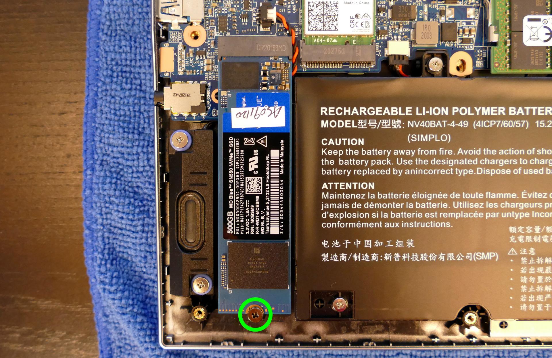
- Remove the existing M.2 drive by pulling it out of the slot.
- Insert the new M.2 drive into the slot and hold it in place.
- Replace the retainer screw.
Replacing the wireless card:
Your Galago Pro's WiFi and Bluetooth are both handled by the same module. It is a standard M.2 2230 slot with PCIe and USB interfaces (E-key).
Tools required: Cross-head (Phillips) screwdriver
Time estimate: 12 minutes
Difficulty: Medium ●
Steps to replace the WiFi/Bluetooth module:
- Follow the steps above to remove the bottom cover.
- Locate the wireless module. Remove any clear tape that is securing the wires.

- Gently remove the two antennas (highlighted red above) by pulling them up and away from the wireless card.
- Remove the retaining screw opposite the M.2 slot, highlighted yellow above.
- The wireless card will pop up at an angle. Remove the card from the M.2 slot.
- Insert the new wireless card into the M.2 slot at an angle.
- Replace the retaining screw.
- Attach the two antennas by aligning the circular fittings and pressing onto the wireless card. The connectors will snap into place. Use caution when attaching the connectors; the pins can bend, break, or snap.
Replacing the CMOS battery:
The CMOS battery supplies power to the system's CMOS chip. UEFI settings and the computer's hardware clock are stored on the CMOS. If your system doesn't boot, you can reset the CMOS to force a low-level hardware reset. If your clock is constantly resetting, it's likely your CMOS battery needs to be replaced.
Warning (ingestion hazard): Keep batteries out of reach of children. Death or serious injury can occur if ingested. If a battery is suspected to be swallowed or inserted inside any part of the body, seek immediate medical attention. In the US, you can also call the National Battery Ingestion Hotline for guidance: 1 (800) 498-8666
Tools required: Cross-head (Phillips) screwdriver
Time estimate: 15 minutes
Difficulty: Medium ●
Steps to replace the CMOS battery:
- Follow the steps above to remove the bottom cover.
- Follow the steps above to remove the M.2 drive, then pull the battery away from the adhesive holding it to the case.
- If you are not replacing the CMOS battery, this step is optional, but will make it easier to unplug the CMOS battery connector.

- Unplug the white connector attaching the CMOS battery to the motherboard (highlighted green above.)
- To clear the CMOS, disconnect the main battery, open the lid of the machine, and hold down the power button for at least 15 seconds to discharge any residual energy in the system.
- Re-connect the CMOS battery and main battery, and replace the M.2 drive and bottom panel.
- Power up the machine. The system may power itself off and on after initial boot; this is normal behavior when the CMOS has been reset.
Replacing the cooling system:
The Galago Pro 5 has a single heatsink for the CPU and GPU (integrated or discrete). One fan is attached to the heatsink, while one additional fan is separate from the heatsink.
If a fan becomes noisy and cleaning it out doesn't fix the issue, you may need a new fan. Contact Support to start a warranty claim or parts purchase.
Depending on your climate and the age of the machine, it may be necessary to apply new thermal paste between the CPU/GPU and the heatsink. Thermal paste helps facilitate effective heat transfer between the CPU/GPU and the cooling equipment. These instructions can also be used in the unlikely event your heatsink needs replacing.
Tools required: Cross-head (Phillips) screwdriver, thermal paste
Time estimate: 20 minutes
Difficulty: High ●
Steps to replace the heatsink/thermal paste:
- Follow the steps above to remove the bottom cover.
- Remove any clear tape that is securing the fan wires.
- Unplug the white fan connector and remove the two fan screws, highlighted yellow below.

- Remove the eight heatsink screws (highlighted cyan above) in order, starting with #1, then #2, and continuing until #8.
- On the Intel-only model, only four heatsink screws are present.
- Remove the heatsink from the system, being careful not to bend the heatsink pipes. It may take some pressure to break the seal of the thermal paste.
- Using a paper towel, remove the existing thermal paste. You may also use a small amount of rubbing alcohol if the old paste is dried or difficult to remove.

- After cleaning the CPU, GPU, and heatsink, apply a small line of thermal paste directly onto the CPU/GPU chips.
- On the Intel-only model, only the CPU chip (on the left) is present.

- Carefully replace the heatsink.
- Replace the eight heatsink screws, starting with #1, then #2, and continuing until #8.
- On the Intel-only model, only four heatsink screws are present.
- Replace the two fan screws and plug in the white fan connector.
Steps to replace the additional fan:
- Follow the steps above to remove the bottom cover.
- Remove any clear tape that is securing the fan wires.
- Remove the two fan screws, highlighted red below.
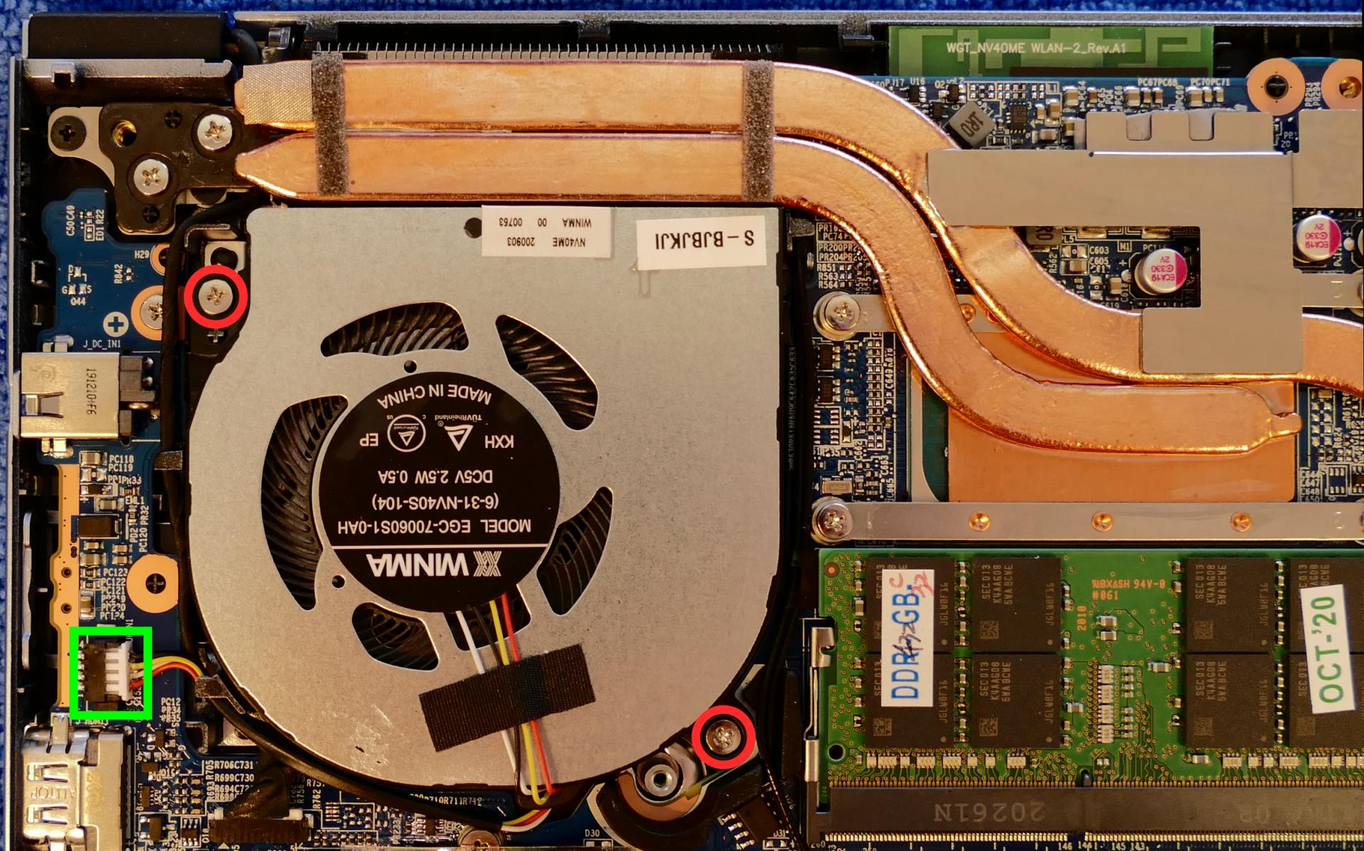
- Unplug the white fan connector, highlighted green above.
- Remove the fan from the system.
Replacing the keyboard:
The keyboard can be replaced using the instructions below.
Tools required: Cross-head (Phillips) screwdriver
Time estimate: 5 minutes
Difficulty: Easy ●
Steps to replace the keyboard:
- Place the machine lid-side down.
- Use a soft surface (such as a towel) to avoid scratches.
- Remove the two keyboard screws, highlighted cyan below.

- Open the lid slightly and place the machine on its side.
- Push the screwdriver into the keyboard push point (highlighted yellow above) until the keyboard pops out.

- Set the machine upright and flip the keyboard down onto the touchpad. The larger ribbon cable is for the keyboard, while the smaller ribbon cable is for the keyboard backlight.

- Flip the black latches away from the white connectors to free the ribbon cables.
- Pull the ribbon cables out of the connectors.
- Remove the keyboard and replace it with the new one.
- Carefully slide both ribbon cables into their connectors.
- Flip the black latches back into place to secure the ribbon cables.
- Place the keyboard back into position, starting with the tabs on the bottom edge.
- Secure the rest of the keyboard by pressing down on each of its edges.
- Turn the machine lid-side down again and replace the two keyboard screws.
Galago Pro (galp4)
The System76 Galago Pro is a laptop with the following specifications:
- CPU
- Supports Intel 10th Generation (Comet Lake-U) CPUs
- BIOS
- GD25B127D flash chip
- SOIC-8 form factor
- Programmed with System76 Open Firmware
- GD25B127D flash chip
- EC
- ITE IT8587E
- Programmed with System76 EC or non-open EC firmware
- Graphics
- GPU: Intel UHD Graphics 620
- eDP display: 14.1" 1920x1080@60Hz LCD
- LCD panel: Innolux N140HCA-EAC (or equivalent)
- External video outputs:
- 1x HDMI
- 1x Mini DisplayPort 1.2
- 1x DisplayPort over USB-C
- Memory
- Up to 64GB (2x32GB) dual-channel DDR4 SO-DIMMs @ 2666 MHz
- Networking
- Gigabit Ethernet
- M.2 PCIe/CNVi WiFi/Bluetooth options:
- Intel Wi-Fi 6 AX200/AX201
- Intel Wireless-AC 9560
- Power
- 40W (19V, 2.1A) DC-in port
- Barrel size: 4mm (outer), 1.7mm (inner)
- Included AC adapter: Chicony A13-040A3A
- AC power cord type: IEC C5
- 35.3Wh 3-cell Lithium-Ion battery
- Model number: N130BAT-3
- 40W (19V, 2.1A) DC-in port
- Sound
- Internal speakers & microphone
- 3.5mm headphone jack
- 3.5mm microphone jack
- HDMI, Mini DisplayPort, USB-C DisplayPort audio
- Storage
- 1x M.2 (PCIe NVMe or SATA) SSD
- 1x 2.5" 7mm SATA drive
- SD card reader
- USB
- 2x USB 3.1 (Gen 1) Type-A
- 1x USB Type-C with Thunderbolt 3
- Dimensions
- 1.8cm x 33cm x 22.5cm, 1.3kg
Galago Pro (External Overview)
Left side overview:

Right side overview:

Front side overview:

Back side overview:

Keyboard Shortcuts
The Galago Pro has the following actions available using the Fn and Function keys:
| Key | Shortcut | Action |
|---|---|---|
 | Fn+F1 | Toggle trackpad |
 | Fn+F2 | Toggle built-in LCD |
 | Fn+F3 | Mute |
 | Fn+F4 | Cycle keyboard backlight brightness |
 | Fn+F5 | Volume down |
 | Fn+F6 | Volume up |
 | Fn+F7 | Toggle displays |
 | Fn+F8 | Screen brightness down |
 | Fn+F9 | Screen brightness up |
 | Fn+F10 | Toggle webcam |
 | Fn+F11 | Toggle airplane mode |
 | Fn+F12 | Suspend |
 | Fn+` | Play/Pause |
| Ins | Fn+Ins | Toggle numpad |
| 1 | Fn+1 | Toggle fan between max/automatic |
LED indicators
The Galago Pro has the following LED indicators:
| Icon | Color | Description |
|---|---|---|
 | Orange | Powered off, DC power plugged in |
| Green | Powered on | |
| Blinking green | Sleeping (suspended) | |
 | Orange | Battery charging |
| Green | Battery fully charged | |
| Blinking orange | Battery critically low | |
 | Green | Airplane mode is on (WiFi/Bluetooth disabled) |
 | Green | Storage drive activity |
Galago Pro (Internal Overview)
Bottom components and connectors:

- RAM slots are highlighted in dark green
- M.2 SSD is highlighted in purple
- Wireless card is highlighted in yellow
- CMOS battery connector is highlighted in solid pink
- CMOS battery is highlighted in dashed pink
- Fan/heatsink module is highlighted in navy
- Fan connector is highlighted in light red
- Webcam/microphone connector is highlighted in orange
- LCD panel connector is highlighted in light green
- Main battery connector is highlighted in cyan
- Main battery is highlighted in brown
- 2.5" drive is highlighted in white
- Speaker connectors are highlighted in maroon
- Speakers are highlighted in olive
- Touchpad connectors are highlighted in dashed red
- Front LED connector is highlighted in dashed yellow
- BIOS flash chip (U25) is highlighted in black
Under-keyboard components and connectors:

- Keyboard connector is highlighted in cyan
- Keyboard backlight connector is highlighted in green
- Power button and left-side USB connector is highlighted in yellow
- Bottom panel screws are highlighted in red
Galago Pro (Parts & Repairs)
Many components in your Galago Pro can be upgraded or replaced as necessary. Follow these step-by-step guides for instructions:
- Replacing the keyboard
- Removing the bottom cover
- Removing the battery
- Replacing the RAM
- Replacing an M.2/NVMe SSD
- Replacing a 2.5" storage drive
- Replacing the WiFi/Bluetooth module
- Replacing the CMOS battery
- Replacing the fans/heatsink/thermal paste
Replacing the keyboard:
The keyboard can be replaced using the instructions below. Removing the keyboard is required for removing the bottom panel.
Tools required: Cross-head (Phillips) screwdriver
Time estimate: 5 minutes
Difficulty: Easy ●
Steps to replace the keyboard:
- Place the machine lid-side down.
- Use a soft surface (such as a towel) to avoid scratches.
- Remove the two keyboard screws, highlighted red below.

- Open the lid slightly and place the machine on its side.
- Push the screwdriver into the keyboard push point (highlighted blue above) until the keyboard pops out.

- Set the machine back down and raise the keyboard away from the chassis. The larger ribbon cable is for the keyboard, while the smaller ribbon cable is for the keyboard backlight.

Note: Unplugging the ribbon cables is not required to remove the bottom cover; the keyboard can be flipped over onto the touchpad without unplugging the ribbon cables.
- Flip the black latches away from the white connectors to free the ribbon cables.
- Pull the ribbon cables out of the connectors.
- Remove the keyboard and replace it with the new one.
- Carefully slide both ribbon cables into their connectors.
- Flip the black latches back into place to secure the ribbon cables.
- Place the keyboard back into position, starting with the tabs on the bottom edge.
- Secure the rest of the keyboard by pressing down on each of its edges.
- Turn the machine lid-side down again and replace the two keyboard screws.
Removing the bottom cover:
Removing the cover is required to access the internal components. Prior to removing the cover, ensure the AC power is unplugged and all peripherals (including SD cards and USB drives) are unplugged or removed from the system.
Tools required: Cross-head (Phillips) screwdriver
Time estimate: 7 minutes
Difficulty: Easy ●
Steps to remove the bottom cover:
- Place the machine lid-side down.
- Use a soft surface (such as a towel) to avoid scratches.
- Remove the 12 bottom panel screws.

- Follow the steps above to remove the keyboard.
- Remove the three under-keyboard screws holding the bottom panel in place from above, highlighted yellow below.

- Lift the bottom panel off, starting from the hinges in the back.
Removing the battery:
The battery provides primary power whenever the system is unplugged.
The model number for the Galago Pro 4's battery is N130BAT-3, and the original part number is 6-87-N130S-3U9A1. Third-party battery sellers may list one or both of these numbers, and may offer other compatible part numbers with the same model number. You can also contact System76 to purchase a replacement battery.
Tools required: Cross-head (Phillips) screwdriver
Time estimate: 10 minutes
Difficulty: Easy ●
Steps to remove the battery:
- Follow the steps above to remove the keyboard and remove the bottom cover.
- Remove the five battery screws, highlighted cyan below.

- Unplug the battery connector (highlighted green above) and lift the battery out of the chassis.
Replacing the RAM:
The Galago Pro 4 supports up to 64GB (2x32GB) of DDR4 SO-DIMMs running at 2666MHz. If you've purchased new RAM, need to replace your RAM, or are reseating your RAM, follow these steps.
Tools required: Cross-head (Phillips) screwdriver
Time estimate: 10 minutes
Difficulty: Easy ●
Steps to replace the RAM:
- Follow the steps above to remove the keyboard and remove the bottom cover.
- Press the small tabs on both sides of the RAM simultaneously. The RAM should spring up to an angle.

- Remove the RAM from the slot.
- Insert the new RAM (or reseat the existing RAM) by placing it in the keyed slot and pressing down until it clicks into place.
Replacing an M.2/NVMe SSD:
This model supports one M.2 SSD of size 2280, either SATA III or PCIe NVMe Generation 3.
Tools required: Cross-head (Phillips) screwdriver
Time estimate: 10 minutes
Difficulty: Easy ●
Steps to replace the M.2 drive:
- Follow the steps above to remove the keyboard and remove the bottom cover.
- Unscrew the retainer screw opposite the M.2 slot.

- Remove the existing M.2 drive by pulling it out of the slot.
- Insert the new M.2 drive into the slot and hold it in place.
- Replace the retainer screw.
- If a square brace was present on the old drive, transfer it to the new drive.
Replacing a 2.5" storage drive:
This model supports one 2.5" (7mm) SATA III SSD or HDD.
Tools required: Cross-head (Phillips) screwdriver
Time estimate: 10 minutes
Difficulty: Easy ●
Steps to replace the 2.5" storage drive:
- Follow the steps above to remove the keyboard and remove the bottom cover.
- Lift the 2.5" drive out of the drive slot.
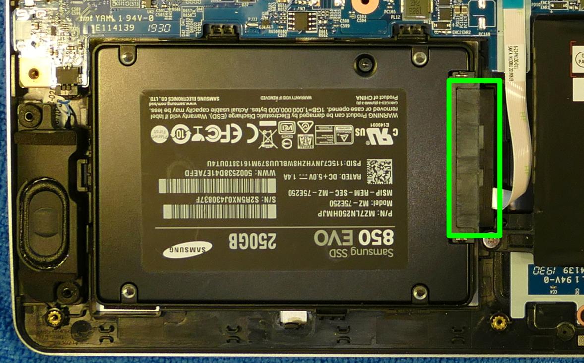
- Unplug the SATA connector (highlighted green above) from the 2.5" drive.
- Plug the SATA connector into the new 2.5" drive and set the drive into the drive slot. (The drive is secured by the bottom cover.)
Replacing the wireless card:
Your Galago Pro's WiFi and Bluetooth are both handled by the same module. It is a standard M.2 2230 slot with PCIe and USB interfaces (E-key).
Tools required: Cross-head (Phillips) screwdriver
Time estimate: 12 minutes
Difficulty: Medium ●
Steps to replace the WiFi/Bluetooth module:
- Follow the steps above to remove the keyboard and remove the bottom cover.
- Locate the wireless module. Remove any clear tape that is securing the wires.

- Gently remove the two antennas (highlighted red above) by pulling them up and away from the wireless card.
- Remove the retaining screw opposite the M.2 slot, highlighted yellow above.
- The wireless card will pop up at an angle. Remove the card from the M.2 slot.
- Insert the new wireless card into the M.2 slot at an angle.
- Replace the retaining screw.
- Attach the two antennas by aligning the circular fittings and pressing onto the wireless card. The connectors will snap into place. Use caution when attaching the connectors; the pins can bend, break, or snap.
Replacing the CMOS battery:
The CMOS battery supplies power to the system's CMOS chip. UEFI settings and the computer's hardware clock are stored on the CMOS. If your system doesn't boot, you can reset the CMOS to force a low-level hardware reset. If your clock is constantly resetting, it's likely your CMOS battery needs to be replaced.
Warning (ingestion hazard): Keep batteries out of reach of children. Death or serious injury can occur if ingested. If a battery is suspected to be swallowed or inserted inside any part of the body, seek immediate medical attention. In the US, you can also call the National Battery Ingestion Hotline for guidance: 1 (800) 498-8666
Tools required: Cross-head (Phillips) screwdriver
Time estimate: 10 minutes
Difficulty: Easy ●
Steps to replace the CMOS battery:
- Follow the steps above to remove the keyboard and remove the bottom cover.
- Unplug the white connector attaching the CMOS battery to the motherboard (highlighted green below.)

- If you are replacing the CMOS battery, pull it away from the adhesive holding it to the case.
- To clear the CMOS, disconnect the main battery, open the lid of the machine, and hold down the power button for at least 15 seconds to discharge any residual energy in the system.
- Re-connect the CMOS battery and the main battery, and replace the bottom panel and keyboard.
- Power up the machine. The system may power itself off and on after initial boot; this is normal behavior when the CMOS has been reset.
Replacing the cooling system:
The Galago Pro 4 has a single fan and heatsink to cool the CPU. The fan and heatsink can be removed or replaced separately from one another.
If the fan becomes noisy and cleaning it out doesn't fix the issue, you may need a new fan. Contact Support to start a warranty claim or parts purchase.
Depending on your climate and the age of the machine, it may be necessary to apply new thermal paste between the CPU and the heatsink. Thermal paste helps facilitate effective heat transfer between the CPU and the cooling equipment. These instructions can also be used in the unlikely event your heatsink needs replacing.
Tools required: Cross-head (Phillips) screwdriver, thermal paste
Time estimate: 20 minutes
Difficulty: High ●
Steps to replace the fan:
- Follow the steps above to remove the keyboard and remove the bottom cover.
- Remove the two fan screws, highlighted green below.

- Unplug the black fan connector, highlighted cyan above. Remove any clear tape that may be holding the wires in place.
- Remove the fan from the system.
Steps to replace the heatsink/thermal paste:
- Follow the steps above to remove the keyboard and remove the bottom cover.
- Remove the three heatsink screws (highlighted red above) in order, starting with #1, then #2, and finally #3.
- Remove the heatsink from the system, being careful not to bend the heatsink pipe. It may take some pressure to break the seal of the thermal paste.
- Using a paper towel, remove the existing thermal paste. You may also use a small amount of rubbing alcohol if the old paste is dried or difficult to remove.

- After cleaning the CPU and heatsink, apply a small line of thermal paste directly onto the CPU chip.

- Carefully replace the heatsink.
- Replace the three heatsink screws, starting with #1, then #2, and finally #3.
Gazelle (gaze18)
The System76 Gazelle is a laptop with the following specifications:
- CPU
- Supports Intel Raptor Lake CPUs
- Chipset
- BIOS
- GigaDevice GD25B256EYIGR flash chip
- WSON-8 form factor
- Programmed with System76 Open Firmware
- GigaDevice GD25B256EYIGR flash chip
- EC
- ITE IT5570E
- Programmed with System76 EC
- Graphics
- Dedicated GPU:
- NVIDIA GeForce RTX 3050
- TGP: 70W (95W boost)
- NVIDIA GeForce RTX 3050
- Integrated GPU:
- Intel Iris Xe Graphics
- eDP display:
- 17.3" 1920x1080@144Hz LCD
- LCD panel options:
- BOE NV173FHM-N4C
- BOE NE173FHM-NX1
- BOE NV173FHM-NY2
- BOE NE173QHM-NY3
- ...or other equivalent
- LCD panel options:
- 15.6" 1920x1080@144Hz LCD
- LCD panel options:
- BOE NV156FHM-N4K
- BOE NV156FHM-NX4
- BOE NE156QHM-NY5
- Innolux N156HCE-EN1
- LCD panel options:
- 17.3" 1920x1080@144Hz LCD
- External video output:
- 1x HDMI 2.1
- 1x Mini DisplayPort 1.4
- Dedicated GPU:
- Memory
- Up to 64GB (2x32GB) dual-channel DDR4 SO-DIMMs @ 3200 MHz
- Networking
- Gigabit Ethernet
- Realtek RTL8111H
- M.2 PCIe/CNVi WiFi/Bluetooth
- Intel Wi-Fi 6E AX210/AX211
- Gigabit Ethernet
- Power
- 150W DC-in port
- Barrel size: 5.5mm (outer), 2.5mm (inner)
- Included AC adapter: LiteOn PA-1151-76
- AC power cord type: IEC C5
- 54Wh 4-cell Lithium-Ion battery
- Model number: NP50BAT-4-54
- 150W DC-in port
- Sound
- Internal speakers & microphone
- Combined headphone & microphone 3.5mm jack
- Dedicated microphone 3.5mm jack
- HDMI, Mini DisplayPort audio
- Storage
- 1x M.2 (PCIe NVMe Gen 4)
- 1x M.2 (PCIe NVMe Gen 3)
- MicroSD card reader
- USB
- 2x USB 3.2 Gen 2 Type-C
- Does not support DisplayPort over USB-C, USB-C charging (USB-PD), or Thunderbolt
- 1x USB 3.2 Gen 2 Type-A
- 1x USB 2.0 Type-A
- 2x USB 3.2 Gen 2 Type-C
- Dimensions
- 15": 35.95cm x 23.8cm x 2.27cm, 1.99kg
- 17": 39.69cm x 26.2cm x 2.5cm, 2.41kg
Gazelle (External Overview)
Left side overview:

Right side overview:

Front side overview:

Back side overview:

Keyboard & touchpad overview:

Materials:
| Part | Material |
|---|---|
| LCD back cover (lid) | Plastic |
| LCD front cover (bezel) | Plastic |
| Top case (palm rests/port covers) | Plastic |
| Bottom panel | Plastic |
LED indicators:
The Gazelle has the following LED indicators:
| Icon | Color | Description |
|---|---|---|
 | Orange | Powered off, DC power plugged in |
| Green | Powered on | |
| Blinking green | Sleeping (suspended) | |
 | Orange | Battery charging |
| Green | Battery fully charged | |
| Blinking orange | Battery critically low | |
 | Green | Storage drive activity |
Keyboard shortcuts:
The Gazelle has the following actions available using the Fn and Function keys:
| Key | Shortcut | Action |
|---|---|---|
 | Fn+F1 | Toggle trackpad |
 | Fn+F2 | Toggle built-in LCD |
 | Fn+F3 | Mute |
 | Fn+F5 | Volume down |
 | Fn+F6 | Volume up |
 | Fn+F7 | Toggle displays |
 | Fn+F8 | Screen brightness down |
 | Fn+F9 | Screen brightness up |
 | Fn+F10 | Toggle webcam |
 | Fn+F11 | Toggle airplane mode |
 | Fn+F12 | Suspend |
 | Fn+` | Play/Pause |
 | Fn+* | Toggle keyboard backlight |
 | Fn+/ | Cycle keyboard color |
 | Fn+- | Decrease keyboard brightness |
 | Fn++ | Increase keyboard brightness |
| 1 | Fn+1 | Toggle fan between max/automatic |
Gazelle (Internal Overview)
Bottom components and connectors:

- LCD panel connector is highlighted in light green
- Keyboard adhesive access point is highlighted in pink
- Fan connectors are highlighted in red
- Webcam/microphone connector is highlighted in yellow
- Speaker connectors are highlighted in cyan
- Main battery connector is highlighted in orange
- Wireless card is highlighted in blue
- RAM is highlighted in maroon
- BIOS flash chip (U24) is highlighted in black
- Touchpad connector is highlighted in white
- M.2 SSDs are highlighted in dark green
- Innermost slot supports PCIe NVMe Gen 4
- Outermost slot supports PCIe NVMe Gen 3
- CMOS battery connector is highlighted in purple
Under-keyboard components and connectors:

- Keyboard adhesive access point is highlighted in green
- Keyboard connector is highlighted in yellow
- Keyboard backlight connector is highlighted in cyan
- Power button/LED connector is highlighted in red
Gazelle (Parts & Repairs)
Many components in your Gazelle can be upgraded or replaced as necessary. Follow these step-by-step guides for instructions:
- Removing the bottom cover
- Replacing the RAM
- Replacing an M.2/NVMe SSD
- Replacing the WiFi/Bluetooth module
- Replacing the battery
- Replacing the CMOS battery
- Replacing the fans/heatsink/thermal paste
- Replacing the keyboard
- Replacing the speakers
Removing the bottom cover:
Removing the cover is required to access the internal components. Prior to removing the cover, ensure the AC power is unplugged and all peripherals (including SD cards and USB drives) are unplugged or removed from the system.
Tools required: Cross-head (Phillips) screwdriver
Time estimate: 5 minutes
Difficulty: Easy ●
Steps to remove the bottom cover:
- Place the machine lid-side down.
- Use a soft surface (such as a towel) to avoid scratches.
- Remove the 13 bottom panel screws.

- Pull the bottom panel off, starting from over the ports in the back.
Replacing the RAM:
The Gazelle 18 supports up to 64GB (2x32GB) of DDR4 SO-DIMMs running at 3200MHz. If you've purchased new RAM, need to replace your RAM, or are reseating your RAM, follow these steps.
Tools required: Cross-head (Phillips) screwdriver
Time estimate: 7 minutes
Difficulty: Easy ●
Steps to replace the RAM:
- Follow the steps above to remove the bottom cover.
- Pull the small tabs on both sides of the RAM simultaneously. The RAM should spring up to an angle.

- Remove the RAM from the slot.
- Insert the new RAM (or reseat the existing RAM) by placing it in the keyed slot and pressing down until it clicks into place.
Replacing an M.2/NVMe SSD:
This model supports up to two M.2 SSDs. Both M.2 slots are size 2280. The inner-most slot supports PCIe NVMe Generation 4, and the outer-most slot supports PCIe NVMe Generation 3.
Tools required: Cross-head (Phillips) screwdriver
Time estimate: 10 minutes
Difficulty: Easy ●
Steps to replace the M.2 drive:
- Follow the steps above to remove the bottom cover.
- Unscrew the retainer screw opposite the M.2 slot.

- Remove the existing M.2 drive by pulling it out of the slot.
- Insert the new M.2 drive into the slot and hold it in place.
- Replace the retainer screw.
Replacing the wireless card:
Your Gazelle's WiFi and Bluetooth are both handled by the same module. It is a standard M.2 2230 slot with PCIe and USB interfaces (E-key).
Tools required: Cross-head (Phillips) screwdriver
Time estimate: 15 minutes
Difficulty: Medium ●
Steps to replace the WiFi/Bluetooth module:
- Follow the steps above to remove the bottom cover.
- Locate the wireless module. Remove any clear tape that is securing the wires.

- Gently remove the two antennas (highlighted red above) by pulling them up and away from the wireless card.
- Remove the retaining screw opposite the M.2 slot, highlighted yellow above.
- The wireless card will pop up at an angle. Remove the card from the M.2 slot.
- Insert the new wireless card into the M.2 slot at an angle.
- Replace the retaining screw.
- Attach the two antennas by aligning the circular fittings and pressing onto the wireless card. The connectors will snap into place. Use caution when attaching the connectors; the pins can bend, break, or snap.
Replacing the battery:
The battery provides primary power whenever the system is unplugged.
The model number for the Gazelle 18's battery is NP50BAT-4-54, and the original part number is 6-87-NP5KS-51B00. Third-party battery sellers may list one or both of these numbers, and may offer other compatible part numbers with the same model number. You can also contact System76 to purchase a replacement battery.
Tools required: Cross-head (Phillips) screwdriver Time estimate: 8 minutes Difficulty: Easy ●
Steps to replace the battery:
- Follow the steps above to remove the bottom cover.
- Remove the five battery screws, highlighted yellow below.

- Unplug the battery connector (highlighted red above) and lift the battery out of the chassis.
Replacing the CMOS battery:
The CMOS battery supplies power to the system's CMOS chip. UEFI settings and the computer's hardware clock are stored on the CMOS. If your system doesn't boot, you can reset the CMOS to force a low-level hardware reset. If your clock is constantly resetting, it's likely your CMOS battery needs to be replaced.
Warning (ingestion hazard): Keep batteries out of reach of children. Death or serious injury can occur if ingested. If a battery is suspected to be swallowed or inserted inside any part of the body, seek immediate medical attention. In the US, you can also call the National Battery Ingestion Hotline for guidance: 1 (800) 498-8666
Tools required: Cross-head (Phillips) screwdriver
Time estimate: 15 minutes
Difficulty: Medium ●
Steps to replace the CMOS battery:
- Follow the steps above to remove the bottom cover.
- Follow the steps above to remove the outermost M.2 drive, then pull the battery away from the adhesive holding it to the case.
- If you are not replacing the CMOS battery, this step is optional, but will make it easier to unplug the CMOS battery connector.
- Unplug the white connector that connects the CMOS battery to the motherboard.

- To clear the CMOS, disconnect the main battery, open the lid of the machine, and hold down the power button for at least 15 seconds to discharge any residual energy in the system.
- Re-connect the CMOS battery.
- Reconnect the main battery, replace the M.2 SSD, and replace the bottom cover.
- Power up the Gazelle. The system may power itself off and on after initial boot; this is normal behavior when the CMOS has been reset.
Replacing the cooling system:
The Gazelle 18 includes two fans as part of a single heatsink/fan assembly.
If the CPU/GPU fans become noisy and cleaning them out doesn't fix the issue, you may need a new fan. Contact support to start a warranty claim or parts purchase.
Thermal paste helps facilitate heat transfer between the CPU/GPU and the cooling equipment. Depending on your climate and the age of the machine, replacing the thermal paste between the CPU/GPU and the heatsink may help the system run cooler.
Tools required: Cross-head (Phillips) screwdriver
Time estimate: 20 minutes
Difficulty: High ●
Steps to replace the fans/heatsink/thermal paste:
- Follow the steps above to remove the bottom cover.
- Remove any clear tape that is securing the fan wires.
- Remove the silver heatsink and fan screws in the order of the stamped numbers, starting with #1, then #2, and continuing until you have removed #12.
- Note: Do not remove the smaller black screws holding the fan covers onto the fans.

- Unplug the two white fan connectors from the motherboard (highlighted cyan above).
- Remove the heatsink/fans from the case, being careful not to bend the heatsink pipes. It may take some pressure to break the seal of the thermal paste.
- Using a paper towel, remove the existing thermal paste. You may also use a small amount of rubbing alcohol if the old paste is dried or difficult to remove.

- After cleaning the CPU, GPU, and heatsink, apply a small line of thermal paste directly onto both CPU chips and the GPU chip.

- Carefully replace the heatsink.
- Replace the silver heatsink and fan screws, starting with #1, then #2, and so on until #12.
- Plug the two white fan connectors back into the motherboard.
Replacing the keyboard:
The keyboard can be replaced if its switches or electronics have been damaged.
Tools required: Cross-head (Phillips) screwdriver, tweezers (optional)
Time estimate: 10 minutes
Difficulty: High ●
Steps to replace the keyboard:
- Follow the steps above to remove the bottom cover.
- Locate the keyboard adhesive strip at the edge of the motherboard underneath the right fan's heatsink pipe, highlighted green below.
- You can optionally remove the heatsink to make the adhesive easier to grasp. Replacing the thermal paste is recommended if the heatsink is removed.

- Using a pair of tweezers to reach the end of the strip (if necessary), pull out the end of the keyboard adhesive strip to stretch and detatch it.
- Open the lid slightly and place the machine on its side.
- Push a screwdriver into the keyboard push point (next to the RAM slot) until the keyboard pops out.


- Set the machine back down and raise the keyboard away from the chassis. The larger ribbon cable is for the keyboard, while the smaller ribbon cable is for the keyboard backlight.

- Flip the black latches upwards to free the ribbon cables.
- Pull the ribbon cables out of the connectors.
- Remove the keyboard and replace it with the new one.
- Carefully slide both ribbon cables into their connectors.
- Flip the black latches back into place to secure the ribbon cables.
- Place the keyboard back into position, starting with the tabs on the bottom edge.
- Secure the rest of the keyboard by pressing down on each of its edges.
- Turn the machine lid-side down again and replace the bottom cover.
Replacing the speakers:
The system has two bottom-firing speakers, which can be removed and replaced individually.
Tools required: Cross-head (Phillips) screwdriver
Time estimate: 10 minutes
Difficulty: Medium ●
Steps to replace the left speaker:
- Follow the steps above to remove the bottom cover and remove the main battery.
- Flip the black latches up to release both sides of the I/O daughterboard ribbon cable from the motherboard and the I/O daughterboard.

- Peel the ribbon cable away from the chassis.
- The ribbon cable is adhered to the chassis. Pull slowly to avoid damage.
- Disconnect the speaker connector from the motherboard.
- This can alternatively be done after freeing the speaker.

- Pull the speaker up and off of the plastic posts, and free the speaker wire from any tape and channels in the chassis.
- Slide the new speaker onto the plastic posts and connect it to the motherboard, securing the wire using the channels in the chassis.
- Reconnect the ribbon cable to the motherboard and I/O daughterboard, then flip the black latches to secure both connections.
- Replace the main battery and bottom cover.
Steps to replace the right speaker:
- Follow the steps above to remove the bottom cover.
- The outermost SSD can optionally be removed to make it easier to work with the speaker plug.
- Disconnect the speaker connector from the motherboard.
- This can alternatively be done after freeing the speaker.

- Pull the speaker up and off of the plastic posts.
- Slide the new speaker onto the plastic posts and connect it to the motherboard.
- Replace the SSD (if necessary) and bottom cover.
Gazelle (gaze17)
The System76 Gazelle is a laptop with the following specifications:
- CPU
- Supports Intel Alder Lake CPUs
- Chipset
- BIOS
- Macronix MX25L25673G flash chip
- WSON-8 form factor
- Programmed with System76 Open Firmware
- Macronix MX25L25673G flash chip
- EC
- ITE IT5570E
- Programmed with System76 EC
- Graphics
- Dedicated GPU options:
- NVIDIA GeForce RTX 3060
- TGP: 60W
- NVIDIA GeForce RTX 3050 Ti
- TGP: 60W
- NVIDIA GeForce RTX 3050
- TGP: 60W
- NVIDIA GeForce RTX 3060
- Integrated GPU:
- Intel Iris Xe Graphics
- eDP display:
- 17.3" 1920x1080@144Hz LCD
- LCD panel: AUO B173HAN04.9 (or equivalent)
- 15.6" 1920x1080@144Hz LCD
- LCD panel: Panda LM156LF-2F01 (or equivalent)
- 17.3" 1920x1080@144Hz LCD
- External video output:
- RTX 3060 model:
- 1x HDMI
- 1x Mini DisplayPort 1.4
- 1x DisplayPort 1.4 over USB-C
- RTX 3050 Ti and 3050 models:
- 1x HDMI
- 1x Mini DisplayPort 1.4
- RTX 3060 model:
- Dedicated GPU options:
- Memory
- Up to 64GB (2x32GB) dual-channel DDR4 SO-DIMMs @ 3200 MHz
- Networking
- Gigabit Ethernet
- Realtek RTL8111H
- M.2 PCIe/CNVi WiFi/Bluetooth
- Intel Wi-Fi 6 AX200/AX201
- Gigabit Ethernet
- Power
- RTX 3060 model:
- 180W DC-in port
- Barrel size: 5.5mm (outer), 2.5mm (inner)
- Included AC adapter: LiteOn PA-1181-76
- AC power cord type: IEC C5
- 180W DC-in port
- RTX 3050 Ti and 3050 models:
- 150W DC-in port
- Barrel size: 5.5mm (outer), 2.5mm (inner)
- Included AC adapter: Chicony A18-150P1A
- AC power cord type: IEC C5
- This model of AC adapter is known to be available with multiple barrel sizes; check the barrel size before purchasing from third parties
- Alternative compatible AC adapter: Chicony A17-150P2A
- 150W DC-in port
- 54Wh 4-cell battery
- Model number: NP50BAT-4-54
- RTX 3060 model:
- Sound
- Internal speakers & microphone
- Combined headphone & microphone 3.5mm jack
- Dedicated microphone 3.5mm jack
- USB-C DisplayPort, HDMI, Mini DisplayPort audio
- Storage
- 1x M.2 (PCIe NVMe Gen 4)
- 1x M.2 (PCIe NVMe Gen 3 or SATA)
- MicroSD card reader
- USB
- RTX 3060 model:
- 1x USB Type-C with Thunderbolt 4
- Supports DisplayPort over USB-C
- Does not support USB-C charging (USB-PD)
- 1x USB 3.2 Gen 2 Type-C
- Does not support DisplayPort over USB-C, USB-C charging (USB-PD), or Thunderbolt
- 1x USB 3.2 Gen 2 Type-A
- 1x USB 2.0 Type-A
- 1x USB Type-C with Thunderbolt 4
- RTX 3050 Ti and 3050 models:
- 2x USB 3.2 Gen 2 Type-C
- Does not support DisplayPort over USB-C, USB-C charging (USB-PD), or Thunderbolt
- 1x USB 3.2 Gen 2 Type-A
- 1x USB 2.0 Type-A
- 2x USB 3.2 Gen 2 Type-C
- RTX 3060 model:
- Dimensions
- 15": 35.95cm x 23.8cm x 2.39cm, 2.05kg
- 17": 39.7cm x 26.213cm x 2.489cm, 2.5kg
Gazelle (External Overview)
Left side overview:

Right side overview:
RTX 3060 model:

RTX 3050 & 3050 Ti models:

Front side overview:

Back side overview:

Keyboard & touchpad overview:

Materials:
| Part | Material |
|---|---|
| LCD back cover (lid) | Plastic |
| LCD front cover (bezel) | Plastic |
| Top case (palm rests/port covers) | Plastic |
| Bottom panel | Plastic |
LED indicators:
The Gazelle has the following LED indicators:
| Icon | Color | Description |
|---|---|---|
 | Orange | Powered off, DC power plugged in |
| Green | Powered on | |
| Blinking green | Sleeping (suspended) | |
 | Orange | Battery charging |
| Green | Battery fully charged | |
| Blinking orange | Battery critically low | |
 | Green | Storage drive activity |
Keyboard shortcuts:
The Gazelle has the following actions available using the Fn and Function keys:
| Key | Shortcut | Action |
|---|---|---|
 | Fn+F1 | Toggle trackpad |
 | Fn+F2 | Toggle built-in LCD |
 | Fn+F3 | Mute |
 | Fn+F5 | Volume down |
 | Fn+F6 | Volume up |
 | Fn+F7 | Toggle displays |
 | Fn+F8 | Screen brightness down |
 | Fn+F9 | Screen brightness up |
 | Fn+F10 | Toggle webcam |
 | Fn+F11 | Toggle airplane mode |
 | Fn+F12 | Suspend |
 | Fn+` | Play/Pause |
 | Fn+* | Toggle keyboard backlight |
| / | Fn+/ | Cycle keyboard color |
| - | Fn+- | Decrease keyboard brightness |
| + | Fn++ | Increase keyboard brightness |
| 1 | Fn+1 | Toggle fan between max/automatic |
Gazelle (Internal Overview)
Bottom components and connectors:

- Webcam/microphone connector is highlighted in pink
- Fan connectors are highlighted in orange
- LCD panel connector is highlighted in green
- Wireless card is highlighted in blue
- RAM is highlighted in red
- M.2 SSDs are highlighted in yellow
- Innermost slot supports PCIe NVMe Gen 4
- Outermost slot supports PCIe NVMe Gen 3 and SATA III
- CMOS battery connector is highlighted in purple
- BIOS flash chip is highlighted in black
- Labeled U55 on 3060 model
- Speaker connectors are highlighted in cyan
- Touchpad connector is highlighted in white
Under-keyboard components and connectors:

- Keyboard adhesive strip is highlighted in green
- Keyboard connector is highlighted in yellow
- Keyboard backlight connector is highlighted in cyan
- Power button/LED connector is highlighted in red
Gazelle (Parts & Repairs)
Many components in your Gazelle can be upgraded or replaced as necessary. Follow these step-by-step guides for instructions:
- Removing the bottom cover
- Replacing the RAM
- Replacing an M.2/NVMe SSD
- Replacing the WiFi/Bluetooth module
- Replacing the battery
- Replacing the CMOS battery
- Replacing the fans/heatsink/thermal paste
- Replacing the keyboard
Removing the bottom cover:
Removing the cover is required to access the internal components. Prior to removing the cover, ensure the AC power is unplugged and all peripherals (including SD cards and USB drives) are unplugged or removed from the system.
Tools required: Cross-head (Phillips) screwdriver
Time estimate: 5 minutes
Difficulty: Easy ●
Steps to remove the bottom cover:
- Place the machine lid-side down.
- Use a soft surface (such as a towel) to avoid scratches.
- Remove the 13 bottom panel screws.

- Pull the bottom panel off, starting from the hinges in the back.
Replacing the RAM:
The Gazelle 17 supports up to 64GB (2x32GB) of DDR4 SO-DIMMs running at 3200MHz. If you've purchased new RAM, need to replace your RAM, or are reseating your RAM, follow these steps.
Tools required: Cross-head (Phillips) screwdriver
Time estimate: 7 minutes
Difficulty: Easy ●
Steps to replace the RAM:
- Follow the steps above to remove the bottom cover.
- Pull the small tabs on both sides of the RAM simultaneously. The RAM should spring up to an angle.

- Remove the RAM from the slot.
- Insert the new RAM (or reseat the existing RAM) by placing it in the keyed slot and pressing down until it clicks into place.
Replacing an M.2/NVMe SSD:
This model supports up to two M.2 SSDs. Both M.2 slots are size 2280. The inner-most slot supports PCIe NVMe Generation 4, and the outer-most slot supports PCIe NVMe Generation 3 or SATA.
Tools required: Cross-head (Phillips) screwdriver
Time estimate: 10 minutes
Difficulty: Easy ●
Steps to replace the M.2 drive:
- Follow the steps above to remove the bottom cover.
- Unscrew the retainer screw opposite the M.2 slot.

- Remove the existing M.2 drive by pulling it out of the slot.
- Insert the new M.2 drive into the slot and hold it in place.
- Replace the retainer screw.
Replacing the wireless card:
Your Gazelle's WiFi and Bluetooth are both handled by the same module. It is a standard M.2 2230 slot with PCIe and USB interfaces (E-key).
Tools required: Cross-head (Phillips) screwdriver
Time estimate: 15 minutes
Difficulty: Medium ●
Steps to replace the WiFi/Bluetooth module:
- Follow the steps above to remove the bottom cover.
- Locate the wireless module. Remove any clear tape that is securing the wires.

- Gently remove the two antennas (highlighted red above) by pulling them up and away from the wireless card.
- Remove the retaining screw opposite the M.2 slot, highlighted yellow above.
- The wireless card will pop up at an angle. Remove the card from the M.2 slot.
- Insert the new wireless card into the M.2 slot at an angle.
- Replace the retaining screw.
- Attach the two antennas by aligning the circular fittings and pressing onto the wireless card. The connectors will snap into place. Use caution when attaching the connectors; the pins can bend, break, or snap.
Replacing the battery:
The battery provides primary power whenever the system is unplugged.
The model number for the Gazelle 17's battery is NP50BAT-4-54, and the original part number is 6-87-NP5KS-53G00. Third-party battery sellers may list one or both of these numbers, and may offer other compatible part numbers with the same model number. You can also contact System76 to purchase a replacement battery.
Tools required: Cross-head (Phillips) screwdriver Time estimate: 8 minutes Difficulty: Easy ●
Steps to replace the battery:
- Follow the steps above to remove the bottom cover.
- Remove the five battery screws, highlighted yellow below.

- Unplug the battery connector (highlighted red above) and lift the battery out of the chassis.
Replacing the CMOS battery:
The CMOS battery supplies power to the system's CMOS chip. UEFI settings and the computer's hardware clock are stored on the CMOS. If your system doesn't boot, you can reset the CMOS to force a low-level hardware reset. If your clock is constantly resetting, it's likely your CMOS battery needs to be replaced.
Warning (ingestion hazard): Keep batteries out of reach of children. Death or serious injury can occur if ingested. If a battery is suspected to be swallowed or inserted inside any part of the body, seek immediate medical attention. In the US, you can also call the National Battery Ingestion Hotline for guidance: 1 (800) 498-8666
Tools required: Cross-head (Phillips) screwdriver
Time estimate: 15 minutes
Difficulty: Medium ●
Steps to replace the CMOS battery:
- Follow the steps above to remove the bottom cover.
- Follow the steps above to remove the outermost M.2 drive, then pull the battery away from the adhesive holding it to the case.
- If you are not replacing the CMOS battery, this step is optional, but will make it easier to unplug the CMOS battery connector.
- Unplug the white connector that connects the CMOS battery to the motherboard.

- To clear the CMOS, disconnect the main battery, open the lid of the machine, and hold down the power button for at least 15 seconds to discharge any residual energy in the system.
- Re-connect the CMOS battery.
- Reconnect the main battery, replace the M.2 SSD, and replace the bottom cover.
- Power up the Gazelle. The system may power itself off and on after initial boot; this is normal behavior when the CMOS has been reset.
Replacing the cooling system:
If the CPU/GPU fans become noisy and cleaning them out doesn't fix the issue, you may need a new fan. Contact Support to start a warranty claim or parts purchase.
Thermal paste helps facilitate heat transfer between the CPU/GPU and the cooling equipment. Depending on your climate and the age of the machine, replacing the thermal paste between the CPU/GPU and the heatsink may help the system run cooler.
Tools required: Cross-head (Phillips) screwdriver
Time estimate: 20 minutes
Difficulty: High ●
Steps to replace the fans/heatsink/thermal paste:
- Follow the steps above to remove the bottom cover.
- Remove any clear tape that is securing the fan wires.
- Remove the silver heatsink screws in the order of the stamped numbers, starting with #1, then #2, and continuing until you have removed #6.

- Remove the six silver screws holding the fans onto the chassis in order, highlighted green above.
- Note: Do not remove the smaller black screws holding the fan covers onto the fans.
- Unplug the two white fan connectors from the motherboard (highlighted cyan above).
- Remove the heatsink/fans from the case, being careful not to bend the heatsink pipes. It may take some pressure to break the seal of the thermal paste.
- Using a paper towel, remove the existing thermal paste. You may also use a small amount of rubbing alcohol if the old paste is dried or difficult to remove.

- After cleaning the CPU, GPU, and heatsink, apply a small line of thermal paste directly onto the CPU and GPU chips.

- Carefully replace the heatsink.
- Replace the silver heatsink screws, starting with #1, then #2, and so on until #6.
- Replace the silver fan screws.
- Plug the two white fan connectors back into the motherboard.
Replacing the keyboard:
The keyboard can be replaced if its switches or electronics have been damaged.
Tools required: Cross-head (Phillips) screwdriver, tweezers (optional)
Time estimate: 10 minutes
Difficulty: High ●
Steps to replace the keyboard:
- Follow the steps above to remove the bottom cover.
- Locate the keyboard adhesive strip at the edge of the motherboard underneath the right fan's heatsink pipe, highlighted green below.

- Using a pair of tweezers, pull out the end of the adhesive strip.
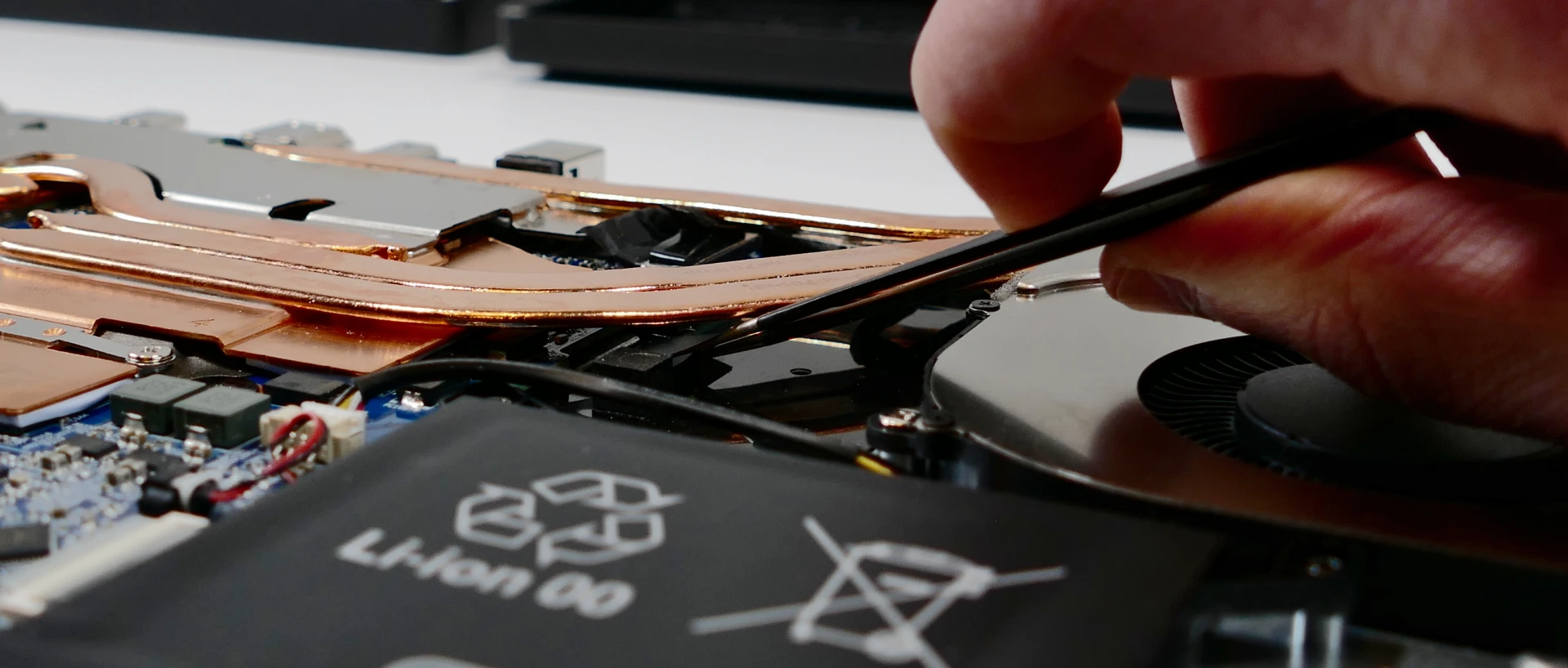
- Alternatively, to remove the keyboard without tweezers, you can remove the heatsink so the adhesive strip is exposed.
- This method is not recommended unless you are also replacing the thermal paste.
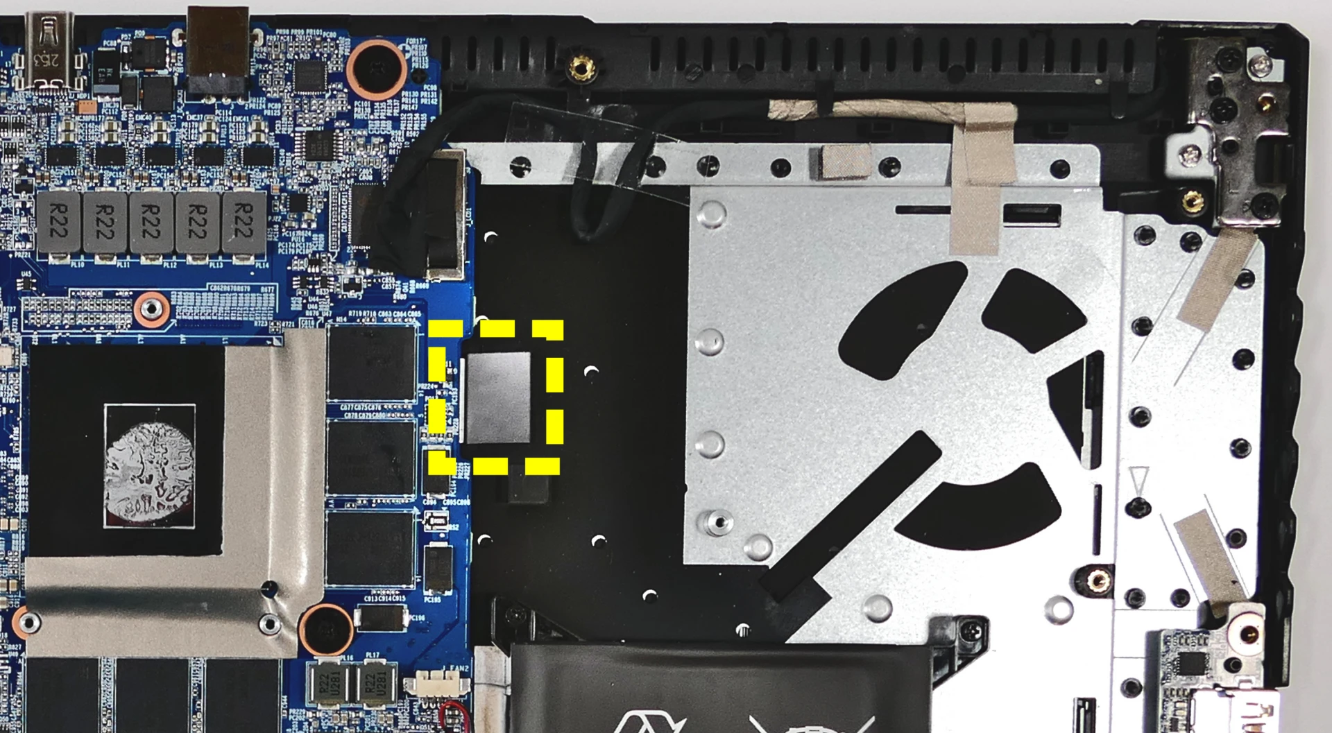
- Open the lid slightly and place the machine on its side.
- Push a screwdriver into the keyboard push point (next to the RAM slot) until the keyboard pops out.

- Set the machine back down and raise the keyboard away from the chassis. The larger ribbon cable is for the keyboard, while the smaller ribbon cable is for the keyboard backlight.

- Flip the black latches upwards to free the ribbon cables.
- Pull the ribbon cables out of the connectors.
- Remove the keyboard and replace it with the new one.
- Carefully slide both ribbon cables into their connectors.
- Flip the black latches back into place to secure the ribbon cables.
- Place the keyboard back into position, starting with the tabs on the bottom edge.
- Secure the rest of the keyboard by pressing down on each of its edges.
- Turn the machine lid-side down again and replace the bottom cover.
Gazelle (gaze16)
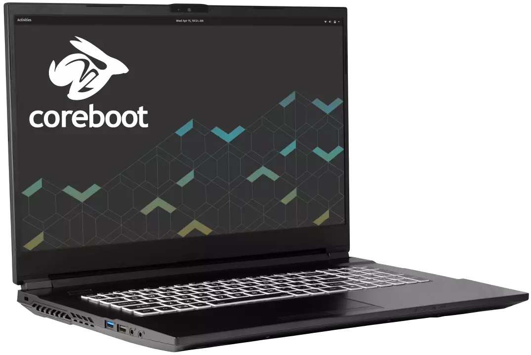
The System76 Gazelle is a laptop with the following specifications:
- CPU
- Supports Intel Tiger Lake CPUs
- Chipset
- BIOS
- GD25B127D flash chip
- SOIC-8 form factor
- Programmed with System76 Open Firmware
- GD25B127D flash chip
- EC
- ITE IT5570E
- Programmed with System76 EC
- Graphics
- GPU options:
- NVIDIA GeForce RTX 3060
- TGP: 60W
- NVIDIA GeForce RTX 3050 Ti
- TGP: 60W
- NVIDIA GeForce RTX 3050
- TGP: 60W
- NVIDIA GeForce RTX 3060
- eDP display options:
- 15.6" 1920x1080@144Hz LCD
- LCD panel: AUO B156HAN08.4 (or equivalent)
- 17.3" 1920x1080@144Hz LCD
- LCD panel: LG LP173WFG-SPB3 (or equivalent)
- 15.6" 1920x1080@144Hz LCD
- External video output:
- RTX 3050 and 3050 Ti models:
- 1x HDMI
- 1x Mini DisplayPort 1.4
- RTX 3060 model:
- 1x HDMI
- 1x Mini DisplayPort 1.2
- 1x DisplayPort 1.4 over USB-C
- RTX 3050 and 3050 Ti models:
- GPU options:
- Memory
- Up to 64GB (2x32GB) dual-channel DDR4 SO-DIMMs @ 3200 MHz
- Networking
- Gigabit Ethernet
- M.2 PCIe/CNVi WiFi/Bluetooth
- Intel Wi-Fi 6 AX200/AX201
- Power
- RTX 3050 and 3050 Ti models:
- 150W DC-in port
- Barrel size: 5.5mm (outer), 2.5mm (inner)
- Included AC adapter: Chicony A17-150P2A
- AC power cord type: IEC C5
- 150W DC-in port
- RTX 3060 model:
- 180W DC-in port
- Barrel size: 5.5mm (outer), 2.5mm (innter)
- Included AC adapter: Chicony A17-180P4A
- AC power cord type: IEC C5
- 180W DC-in port
- 48.96Wh 4-cell battery
- Model number: NH50BAT-4
- RTX 3050 and 3050 Ti models:
- Sound
- Internal speakers & microphone
- Combined headphone & microphone 3.5mm jack
- Dedicated microphone 3.5mm jack
- USB-C DisplayPort (3060 only), HDMI, Mini DisplayPort audio
- Storage
- 1x M.2 (PCIe NVMe Gen 4)
- 1x M.2 (PCIe NVMe Gen 3 or SATA)
- 2.5" 7mm SATA drive bay
- SD card reader
- USB
- 1x USB 3.2 Gen 2 Type-C
- Supports DisplayPort over USB-C on RTX 3060 model only
- Does not support USB-C charging (USB-PD) or Thunderbolt
- 1x USB 3.2 Gen 2 Type-A
- 1x USB 3.2 Gen 1 Type-A
- 1x USB 2.0 Type-A
- 1x USB 3.2 Gen 2 Type-C
- Dimensions
- 15": 35.75cm x 23.8cm x 1.98cm, 1.99kg
- 17": 39.59cm x 26.495cm x 1.99cm, 2.3kg
Gazelle (External Overview)
15" models:
Left side:
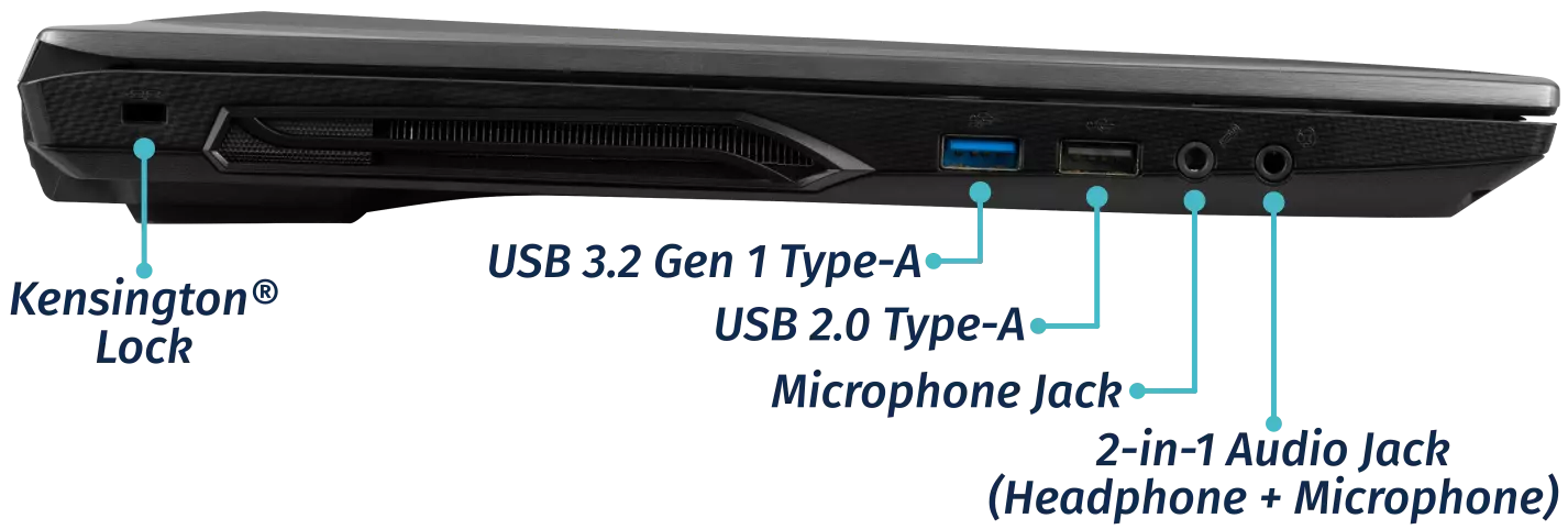
Right side:
3050 & 3050 Ti:

3060:

Front side:

Back side:
3050 & 3050 Ti:

3060:

17" models:
Left side:

Right side:
3050 & 3050 Ti:

3060:

Front side:

Back side:
3050 & 3050 Ti:

3060:

Lid/chassis design differences:
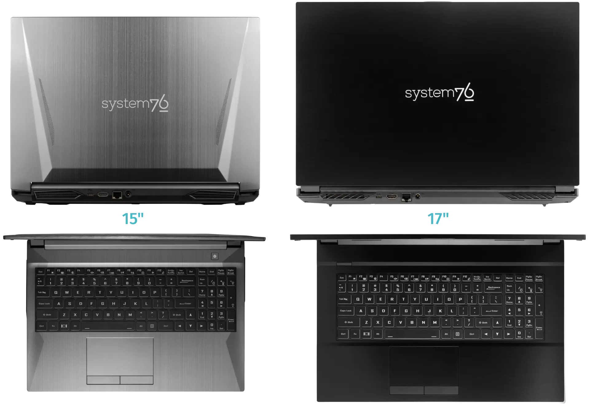
Materials:
15" model:
| Part | Material |
|---|---|
| LCD back cover (lid) | Aluminum |
| LCD front cover (bezel) | Plastic |
| Top case (palm rests/port covers) | Plastic |
| Bottom panel | Plastic |
17" model:
| Part | Material |
|---|---|
| LCD back cover (lid) | Plastic |
| LCD front cover (bezel) | Plastic |
| Top case (palm rests/port covers) | Plastic |
| Bottom panel | Plastic |
LED indicators:
The Gazelle has the following LED indicators:
| Icon | Color | Description |
|---|---|---|
 | Orange | Powered off, DC power plugged in |
| Green | Powered on | |
| Blinking green | Sleeping (suspended) | |
 | Orange | Battery charging |
| Green | Battery fully charged | |
| Blinking orange | Battery critically low | |
 | Green | Storage drive activity |
Keyboard shortcuts:
The Gazelle has the following actions available using the Fn and Function keys:
| Key | Shortcut | Action |
|---|---|---|
 | Fn+F1 | Toggle trackpad |
 | Fn+F2 | Toggle built-in LCD |
 | Fn+F3 | Mute |
 | Fn+F5 | Volume down |
 | Fn+F6 | Volume up |
 | Fn+F7 | Toggle displays |
 | Fn+F8 | Screen brightness down |
 | Fn+F9 | Screen brightness up |
 | Fn+F10 | Toggle webcam |
 | Fn+F11 | Toggle airplane mode |
 | Fn+F12 | Suspend |
 | Fn+` | Play/Pause |
 | Fn+* | Toggle keyboard backlight |
| / | Fn+/ | Cycle keyboard color |
| - | Fn+- | Decrease keyboard brightness |
| + | Fn++ | Increase keyboard brightness |
Gazelle (Internal Overview)
Bottom components and connectors:

- Webcam/microphone connector is highlighted in pink
- Fan connectors are highlighted in orange
- LCD panel connector is highlighted in red
- Wireless card is highlighted in blue
- RAM is highlighted in dark green
- M.2 SSDs are highlighted in yellow
- 2.5" storage drive is highlighted in purple
- CMOS battery connector is highlighted in cyan
- BIOS flash chip is highlighted in black
- Labeled U51 on 3050/3050 Ti models
- Labeled U52 on 3060 model
- Speaker connectors are highlighted in light green
- Touchpad connector is highlighted in white
Under-keyboard components and connectors:

- Keyboard connector is highlighted in yellow
- Keyboard backlight connector is highlighted in cyan
- Power button/LED connector is highlighted in red
Gazelle (Parts & Repairs)
Many components in your Gazelle can be upgraded or replaced as necessary. This page uses photos of the 15" model, but screw counts, general component locations, and other details are the same on the 17" model unless otherwise noted.
- Removing the battery
- Removing the bottom cover
- Replacing the RAM
- Replacing an M.2/NVMe SSD
- Replacing the WiFi/Bluetooth module
- Replacing the CMOS battery
- Replacing a 2.5" storage drive
- Replacing the fans/heatsink/thermal paste
- Replacing the keyboard
Removing the battery:
The battery provides primary power whenever the system is unplugged.
The model number for the Gazelle 16's battery is NH50BAT-4, and the original part number is 6-87-NH50S-42D01. Third-party battery sellers may list one or both of these numbers, and may offer other compatible part numbers with the same model number. You can also contact System76 to purchase a replacement battery.
Tools required: None
Time estimate: 1 minute
Difficulty: Easy ●
Steps to remove the battery:
- Place the machine lid-side down.
- Use a soft surface (such as a towel) to avoid scratches.
- Slide the locking slider (highlighted cyan below) into the unlocked position.

- While holding the springing slider (highlighted red above) in the unlocked position, grasp the tab in the corner and lift the battery out of the machine.
Removing the bottom cover:
Removing the cover is required to access the internal components. Prior to removing the cover, ensure the AC power is unplugged and all peripherals (including SD cards and USB drives) are unplugged or removed from the system.
Tools required: Cross-head (Phillips) screwdriver
Time estimate: 5 minutes
Difficulty: Easy ●
Steps to remove the bottom cover:
-
Follow the steps above to remove the battery.
-
Remove the bottom panel screws.
- On the 15" model:
- There are 16 screws total.
- The two back corner screws (highlighted red below) are slightly longer than the rest.
- The silver hinge screw (highlighted cyan below) is slightly shorter than the rest.
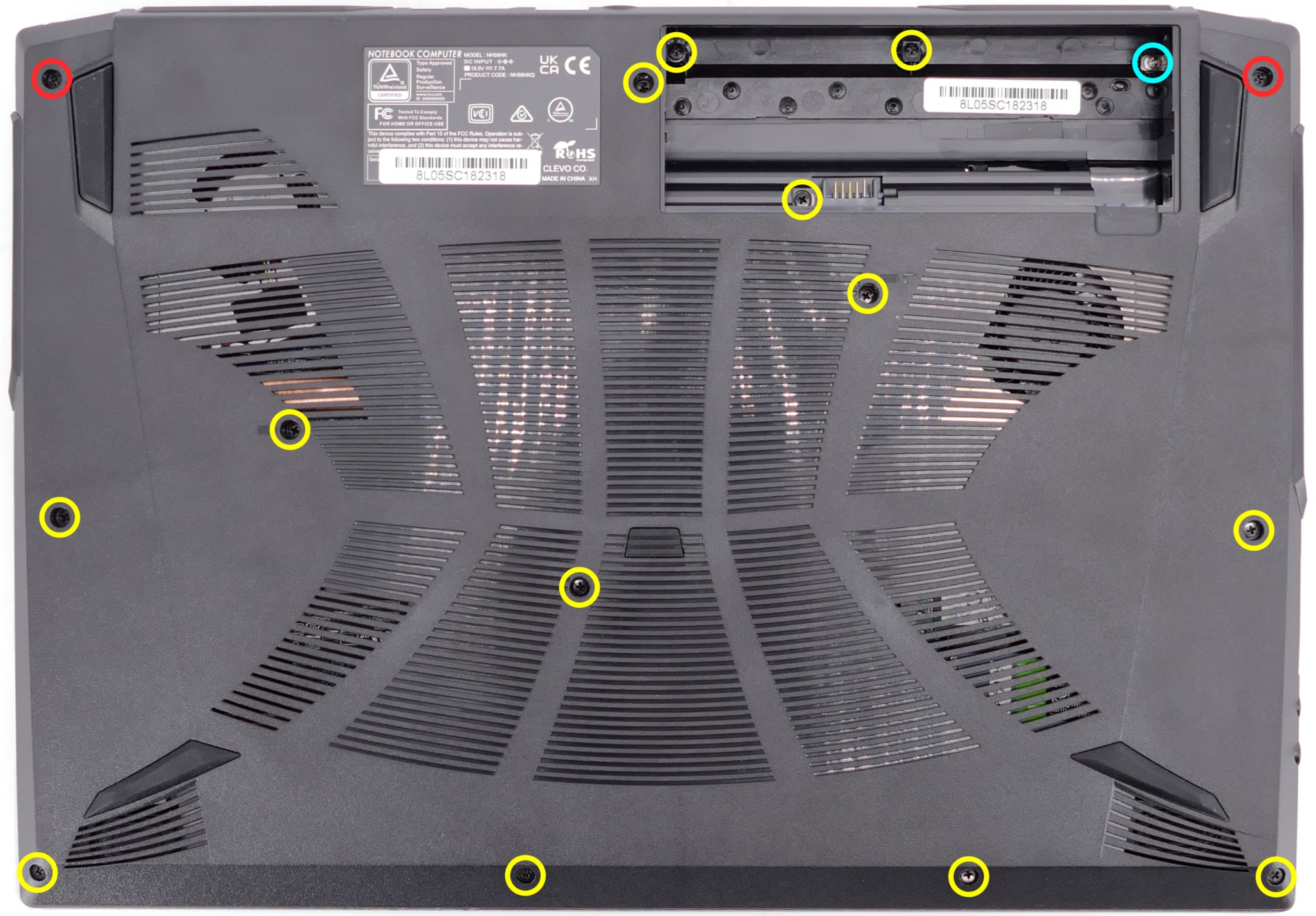
- On the 17" model:
- There are 17 screws total.
- The battery connector screw (highlighted cyan below) is the shortest.
- The other two under-battery screws (highlighted green below) may also be shorter than the rest.
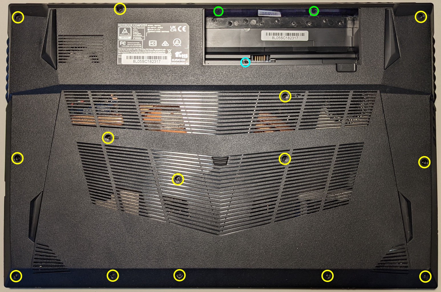
- On the 15" model:
-
Pull the bottom panel off of the case, starting behind the battery slot.
Replacing the RAM:
The Gazelle 16 supports up to 64GB (2x32GB) of DDR4 SO-DIMMs running at 3200MHz. If you've purchased new RAM, need to replace your RAM, or are reseating your RAM, follow these steps.
Tools required: Cross-head (Phillips) screwdriver
Time estimate: 7 minutes
Difficulty: Easy ●
Steps to replace the RAM:
- Follow the steps above to remove the battery and remove the bottom cover.
- Press the small tabs on both sides of the RAM simultaneously. The RAM should spring up to an angle.

- Remove the RAM from the slot.
- Insert the new RAM (or reseat the existing RAM) by placing it in the keyed slot and pressing down until it clicks into place.
Replacing an M.2/NVMe SSD:
This model supports up to two M.2 SSDs. Both M.2 slots are size 2280. The outer-most slot (farthest away from the fans) supports PCIe NVMe Generation 4, and the inner-most slot (closest to the fans) supports SATA or PCIe NVMe Generation 3.
Tools required: Cross-head (Phillips) screwdriver
Time estimate: 10 minutes
Difficulty: Easy ●
Steps to replace the M.2 drive:
- Follow the steps above to remove the battery and remove the bottom cover.
- Unscrew the retainer screw opposite the M.2 slot.

- Remove the existing M.2 drive by pulling it out of the slot.
- Insert the new M.2 drive into the slot and hold it in place.
- Replace the retainer screw.
Replacing the wireless card:
Your Gazelle's WiFi and Bluetooth are both handled by the same module. It is a standard M.2 2230 slot with PCIe and USB interfaces (E-key).
Tools required: Cross-head (Phillips) screwdriver
Time estimate: 15 minutes
Difficulty: Medium ●
Steps to replace the WiFi/Bluetooth module:
- Follow the steps above to remove the battery and remove the bottom cover.
- Locate the wireless module. Remove any clear tape that is securing the wires.

- Gently remove the two antennas (highlighted red above) by pulling them up and away from the wireless card.
- Remove the retaining screw opposite the M.2 slot, highlighted yellow above.
- The wireless card will pop up at an angle. Remove the card from the M.2 slot.
- Insert the new wireless card into the M.2 slot at an angle.
- Replace the retaining screw.
- Attach the two antennas by aligning the circular fittings and pressing onto the wireless card. The connectors will snap into place. Use caution when attaching the connectors; the pins can bend, break, or snap.
Replacing the CMOS battery:
The CMOS battery supplies power to the system's CMOS chip. UEFI settings and the computer's hardware clock are stored on the CMOS. If your system doesn't boot, you can reset the CMOS to force a low-level hardware reset. If your clock is constantly resetting, it's likely your CMOS battery needs to be replaced.
Warning (ingestion hazard): Keep batteries out of reach of children. Death or serious injury can occur if ingested. If a battery is suspected to be swallowed or inserted inside any part of the body, seek immediate medical attention. In the US, you can also call the National Battery Ingestion Hotline for guidance: 1 (800) 498-8666
Tools required: Cross-head (Phillips) screwdriver
Time estimate: 15 minutes
Difficulty: Medium ●
Steps to replace the CMOS battery:
- Follow the steps above to remove the main battery and remove the bottom cover.
- Unplug the white connector that connects the CMOS battery to the motherboard.

- If you are replacing the battery, remove any clear tape holding the battery in place and gently pull the battery up from where it's stuck to the case.
- To clear the CMOS, open the lid of the machine and hold down the power button for at least 15 seconds to discharge any residual energy in the system.
- Re-connect the CMOS battery.
- Replace the M.2 SSD, replace the bottom cover, and replace the main battery.
- Power up the Gazelle. The system may power itself off and on after initial boot; this is normal behavior when the CMOS has been reset.
Replacing a 2.5" storage drive:
This model supports one 2.5" (7mm height) SATA III SSD or hard drive.
Tools required: Cross-head (Phillips) screwdriver
Time estimate: 15 minutes
Difficulty: Medium ●
Steps to replace a 2.5" storage drive:
- Follow the steps above to remove the battery and remove the bottom cover.
- Unscrew the single screw holding the 2.5" drive bracket into the case.

- Slightly lift the loose end of the 2.5" drive and slide it out of the SATA port.

- Unscrew the two screws holding the 2.5" drive into the drive bracket (one on either side.)

- Insert the new 2.5" drive into the drive bracket and replace the two side screws.
- Plug the 2.5" drive into the SATA port and set the drive into the case.
- Screw the drive bracket back into the case.
Replacing the cooling system:
If the CPU/GPU fans become noisy and cleaning them out doesn't fix the issue, you may need a new fan. Contact Support to start a warranty claim or parts purchase.
Thermal paste helps facilitate heat transfer between the CPU/GPU and the cooling equipment. Depending on your climate and the age of the machine, replacing the thermal paste between the CPU/GPU and the heatsink may help the system run cooler.
Tools required: Cross-head (Phillips) screwdriver
Time estimate: 20 minutes
Difficulty: High ●
Steps to replace the fans/heatsink/thermal paste:
- Follow the steps above to remove the battery and remove the bottom cover.
- Remove the silver heatsink screws in the order of the stamped numbers, starting with #1, then #2, and continuing until you have removed #8.
- The order for the 15" model is shown below; the screws are numbered differently on the 17" model. Follow the order stamped into the heatsink metal.

- Remove the black screws holding the fans onto the chassis in order, starting with #9 and continuing through #14.
- Note: Do not remove the smaller black screws holding the fan covers onto the fans.
- If there is any clear tape securing the heatsink/fans or the fan wires, remove it.
- Unplug the two white fan connectors from the motherboard (highlighted cyan above).
- Remove the heatsink/fans from the case, being careful not to bend the heatsink pipes. It may take some pressure to break the seal of the thermal paste.
- Using a paper towel, remove the existing thermal paste. You may also use a small amount of rubbing alcohol if the old paste is dried or difficult to remove.

- After cleaning the CPU, GPU, and heatsink, apply a small line of thermal paste directly onto the CPU and GPU chips.

- Carefully replace the heatsink.
- Replace the silver heatsink screws, starting with #1, then #2, and so on until #8.
- Replace the black fan screws, starting with #9 and continuing through #14.
- Plug the two white fan connectors back into the motherboard.
Replacing the keyboard:
Keyboard replacement is simple and requires only a cross-head screwdriver.
Tools required: Cross-head (Phillips) screwdriver
Time estimate: 5 minutes
Difficulty: Medium ●
Steps to replace the keyboard:
- Place the machine lid-side down.
- Use a soft surface (such as a towel) to avoid scratches.
- Remove the 2 keyboard screws, indicated by the small keyboard icons.

- Open the lid slightly and place the machine on its side.
- Push the screwdriver into the keyboard push point (highlighted red above) until the keyboard pops out.

- Set the machine back down and raise the keyboard away from the chassis. The larger ribbon cable is for the keyboard, while the smaller ribbon cable is for the keyboard backlight.

- Flip the black latches upwards to free the ribbon cables.
- Pull the ribbon cables out of the connectors.
- Remove the keyboard and replace it with the new one.
- Carefully slide both ribbon cables into their connectors.
- Flip the black latches back into place to secure the ribbon cables.
- Place the keyboard back into position, starting with the tabs on the bottom edge.
- Secure the rest of the keyboard by pressing down on each of its edges.
- Turn the machine lid-side down again and replace the two keyboard screws.
Gazelle (gaze15)
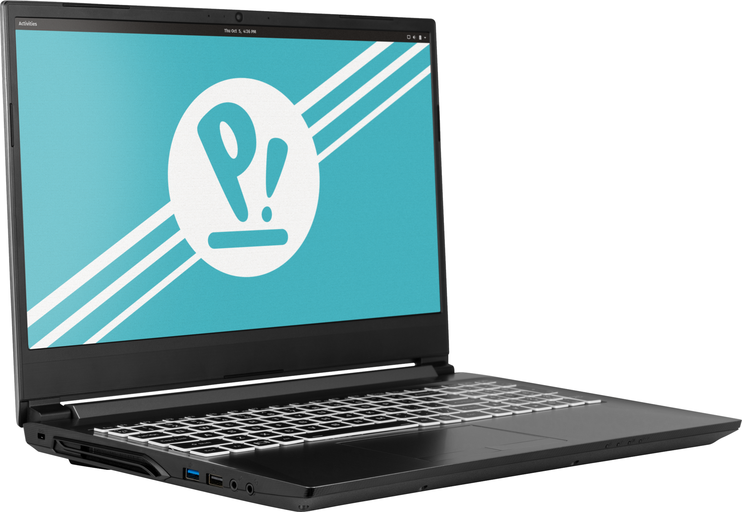
The System76 Gazelle is a laptop with the following specifications:
- CPU
- Supports Intel Comet Lake CPUs
- BIOS
- GD25B127D flash chip
- SOIC-8 form factor
- Programmed with System76 Firmware (non-open)
- GD25B127D flash chip
- EC
- ITE IT5570E
- Programmed with non-open EC firmware
- Graphics
- GPU options:
- NVIDIA GeForce GTX 1650
- NVIDIA GeForce GTX 1650 Ti
- NVIDIA GeForce GTX 1660 Ti
- eDP display options:
- 15.6" 1920x1080@120Hz LCD
- LCD panel: Panda LM156LF2F (or equivalent)
- 17.3" 1920x1080@120Hz LCD
- LCD panel: AUO B173HAN04.7 (or equivalent)
- 15.6" 1920x1080@120Hz LCD
- External video outputs:
- 1x HDMI
- 1x Mini DisplayPort 1.4
- (1660 Ti model only) 1x DisplayPort 1.4 over USB 3.1 Type-C
- GPU options:
- Memory
- Up to 64GB dual-channel DDR4 @ 2666 MHz, or
- Up to 32GB dual-channel DDR4 @ 2933 MHz
- Networking
- Gigabit Ethernet
- M.2 PCIe/CNVi WiFi/Bluetooth
- Intel Wireless-AC 9560, or
- Intel Wi-Fi 6 AX200/AX201
- Power
- GTX 1650 and 1650 Ti models:
- 120W DC-in port
- Barrel size: 5.5mm (outer), 2.5mm (inner)
- Included AC adapter: Chicony A17-120P1A
- AC power cord type: IEC C5
- 120W DC-in port
- GTX 1660 Ti model:
- 180W DC-in port
- Barrel size: 5.5mm (outer), 2.5mm (innter)
- Included AC adapter: Chicony A17-180P4A
- AC power cord type: IEC C5
- 180W DC-in port
- 48.96Wh 4-cell Lithium-Ion battery
- Model number: NH50BAT-4
- GTX 1650 and 1650 Ti models:
- Sound
- Internal speaker & microphone
- Combined headphone/microphone 3.5-mm jack
- HDMI, Mini DisplayPort, USB-C DisplayPort audio
- Storage
- M.2 PCIe/SATA SSD-1
- M.2 PCIe SSD-2
- 2.5" 7mm SATA drive bay
- SD card reader
- USB
- GTX 1650 & 1650 Ti:
- 1 x USB 2.0
- 1 x USB 3.0
- 1 x USB 3.1
- 1 x USB 3.2 Type-C
- GTX 1660 Ti:
- 1 x USB 2.0
- 1 x USB 3.0
- 1 x USB 3.1
- 1 x USB 3.2 Type-C with DisplayPort 1.4
- GTX 1650 & 1650 Ti:
Gazelle (External Overview)
Left side overview:
1650 & 1650 Ti
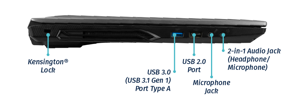
1660 Ti
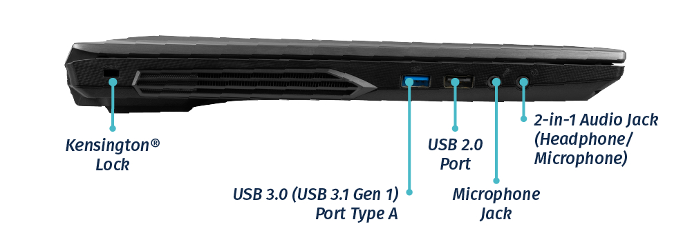
Right side overview:
1650 & 1650 Ti
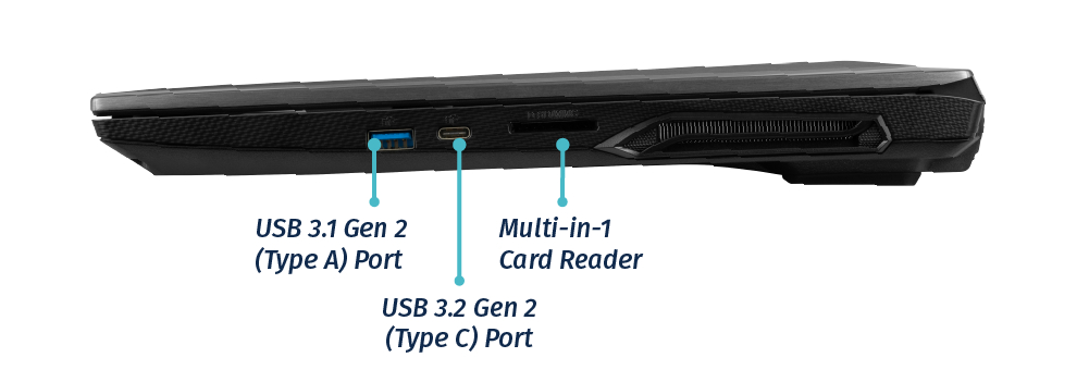
1660 Ti
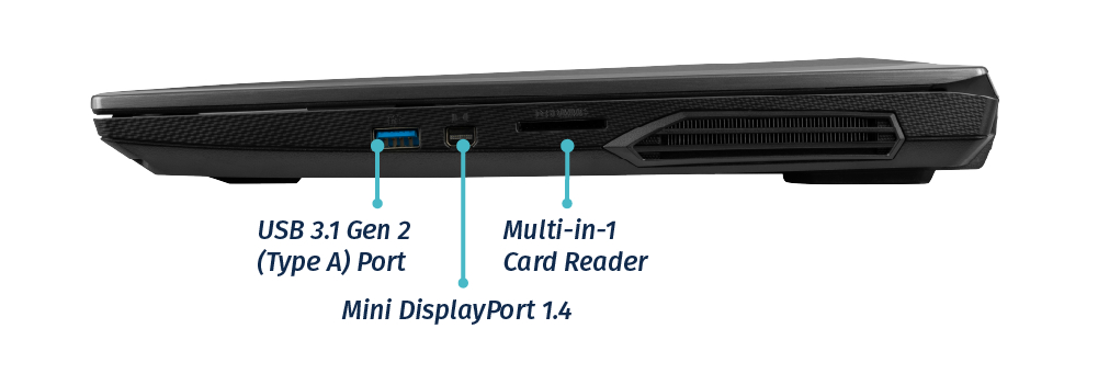
Front side overview:

Back side overview:
1650 & 1650 Ti
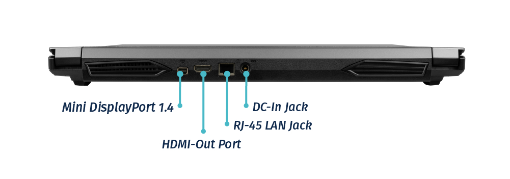
1660 Ti
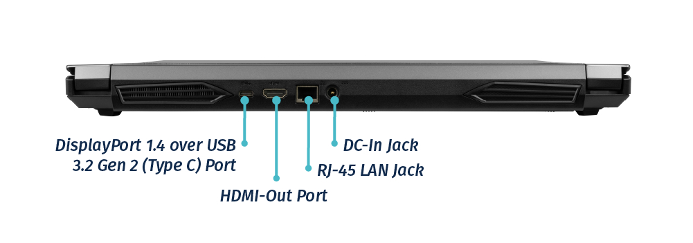
Keyboard Shortcuts
The Gazelle has the following actions available using the Fn and Function keys:
| Key | Shortcut | Action |
|---|---|---|
 | Fn+F1 | Toggle trackpad |
 | Fn+F2 | Lock screen and toggle built-in LCD |
 | Fn+F3 | Mute |
 | Fn+F5 | Volume down |
 | Fn+F6 | Volume up |
 | Fn+F7 | Toggle displays |
 | Fn+F8 | Screen brightness down |
 | Fn+F9 | Screen brightness up |
 | Fn+F10 | Toggle webcam |
 | Fn+F11 | Toggle airplane mode |
 | Fn+F12 | Suspend |
 | Fn+` | Play/Pause |
| 1 | Fn+1 | Toggle fan between max/automatic |
 | Fn+* | Toggle keyboard backlight |
| / | Fn+/ | Cycle keyboard color |
| - | Fn+- | Decrease keyboard brightness |
| + | Fn++ | Increase keyboard brightness |
LED indicators
The Gazelle 15 has the following LED indicators:
| Icon | Color | Description |
|---|---|---|
 | Orange | DC power plugged in |
| Green | Computer is on | |
| Blinking green | Computer is sleeping | |
 | Orange | Battery charging |
| Green | Battery fully charged | |
| Blinking orange | Battery critically low | |
 | Green | Airplane mode is on (WiFi/Bluetooth disabled) |
 | Green | Storage drive activity |
Gazelle (Internal Overview)
Bottom components and connectors:
The following components can be replaced using the instructions under Parts & Repairs.

- Battery slot is highlighted in white
- Wireless card is highlighted in pink
- RAM slots are highlighted in green
- 2.5" 7mm drive bay is highlighted in navy
- M.2 PCIe NVMe/SATA SSD slot is highlighted in orange
- M.2 PCIe NVMe SSD slot is highlighted in cyan
- CMOS battery connector is highlighted in yellow
- Fan connectors are highlighted in red
- BIOS flash chip (U46 for 15", U40 for 17") is highlighted in black
Gazelle (Parts & Repairs)
Many components in your Gazelle can be upgraded or replaced as necessary. Individual component or connector locations may vary between the 15" and 17" models, but steps remain the same unless otherwise noted.
- Replacing the keyboard
- Removing the bottom cover
- Replacing the RAM
- Replacing an M.2/NVMe SSD
- Replacing a 2.5" storage drive
- Replacing the fans/heatsink/thermal paste
- Replacing the CMOS battery
- Replacing the external battery
- Replacing the WiFi/Bluetooth module
Replacing the keyboard:
Keyboard replacement is simple and requires only a cross-head screwdriver.
Tools required: Cross-head (Phillips) screwdriver
Time estimate: 5 minutes
Difficulty: Easy ●
Screws: 2 total - 2 x M2 (black)
Steps to replace the keyboard:
- Place the machine lid-side down.
- Use a soft surface (such as a towel) to avoid scratches.
- Remove the two keyboard screws, indicated by the small keyboard icons (highlighted yellow below).
15" version:
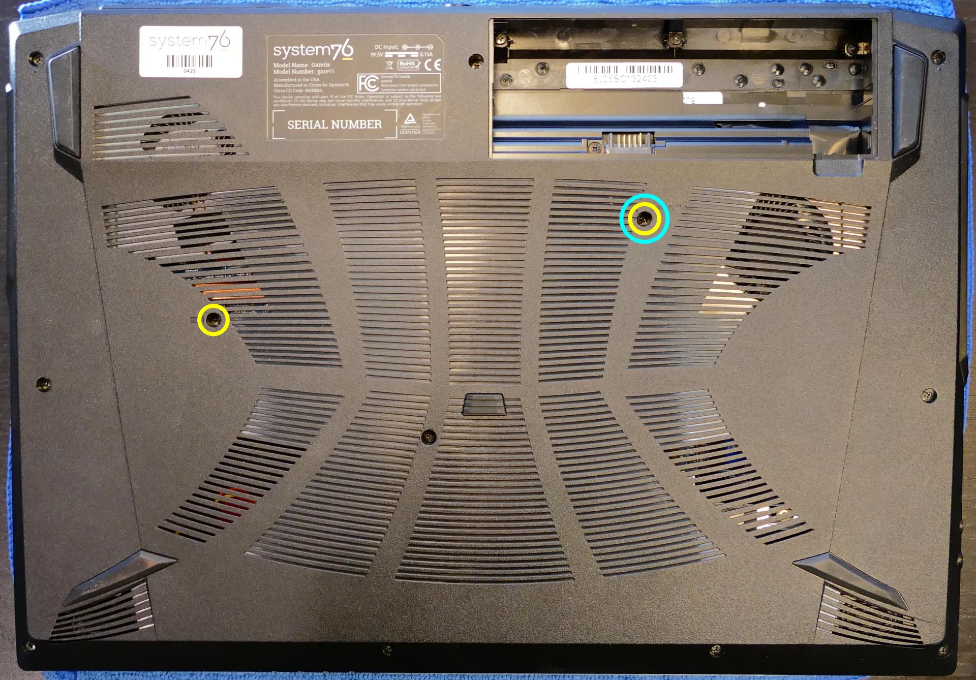
17" version:
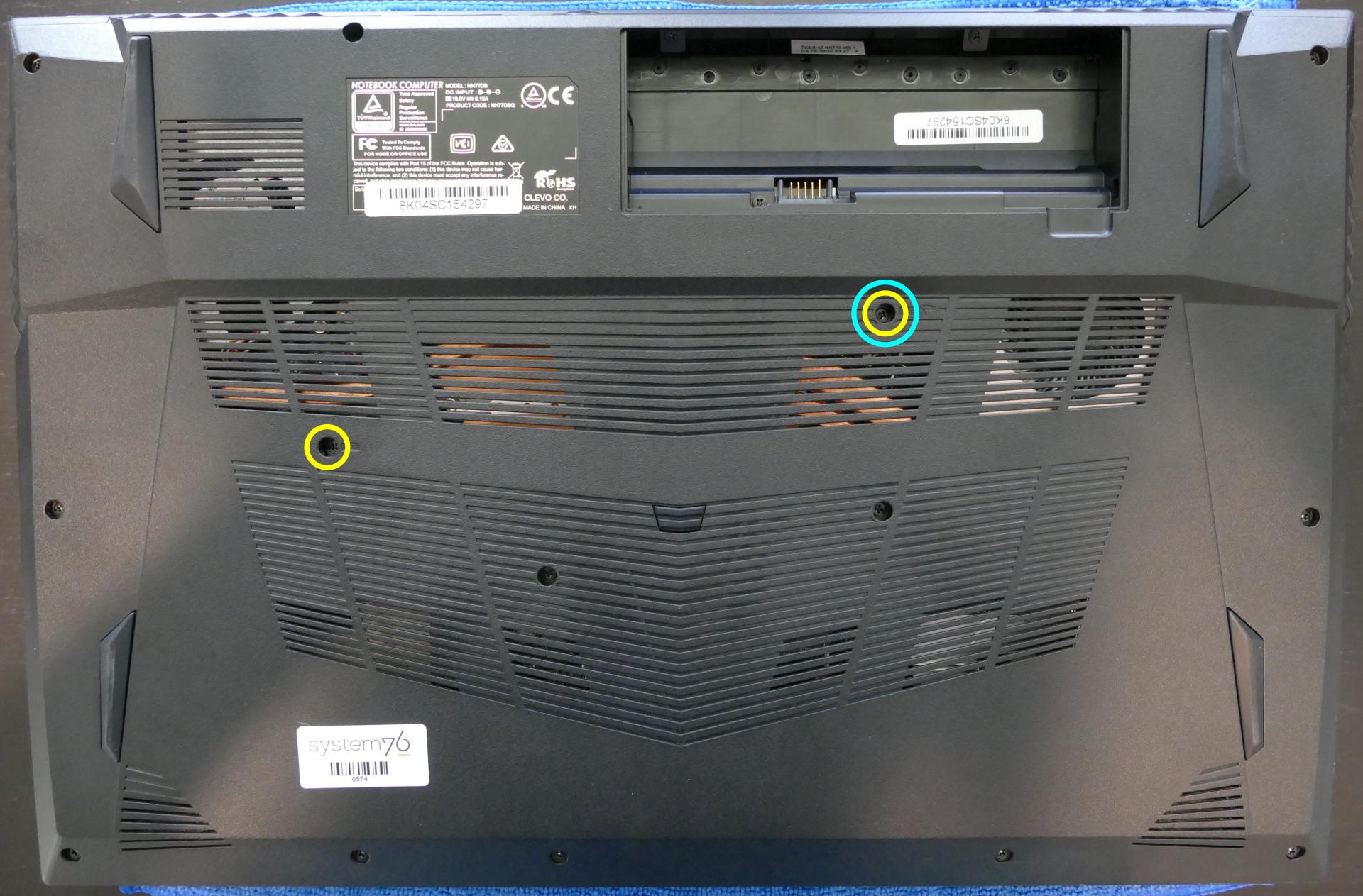
- Open the Gazelle and place it on its side.
- Push the screwdriver into the keyboard push point (highlighted cyan above) until the keyboard pops out.

- Set the machine back down and raise the keyboard away from the chassis. The larger ribbon cable is for the keyboard, while the smaller ribbon cable is for the keyboard backlight.

- Flip the black latches upwards to free the ribbon cables.
- Pull the ribbon cables out of the connectors.
- Remove the keyboard and replace it with the new one.
- Carefully slide both ribbon cables into their connectors.
- Flip the black latches back into place to secure the ribbon cables.
- Place the keyboard back into position, starting with the tabs on the bottom edge.
- Secure the rest of the keyboard by pressing down on each of its edges.
- Turn the machine lid-side down again and replace the two keyboard screws.
Removing the bottom cover:
Removing the cover is required to access the internal components. Prior to removing the cover, ensure the AC power is unplugged and all peripherals (including SD cards and USB drives) are unplugged or removed from the system.
Tools required: Cross-head (Phillips) screwdriver
Time estimate: 5 minutes
Difficulty: Easy ●
Screws: 17 total - 12 x M2 (black); 2 x M2 keyboard (black); 3 x M2 under-battery (black)
Steps to remove the bottom cover:
- Place the machine lid-side down.
- Use a soft surface (such as a towel) to avoid scratches.
- Remove the external battery.
- Remove the bottom panel screws.
15": version: 10 unmarked screws, 2 keyboard screws, and 4 under-battery screws.
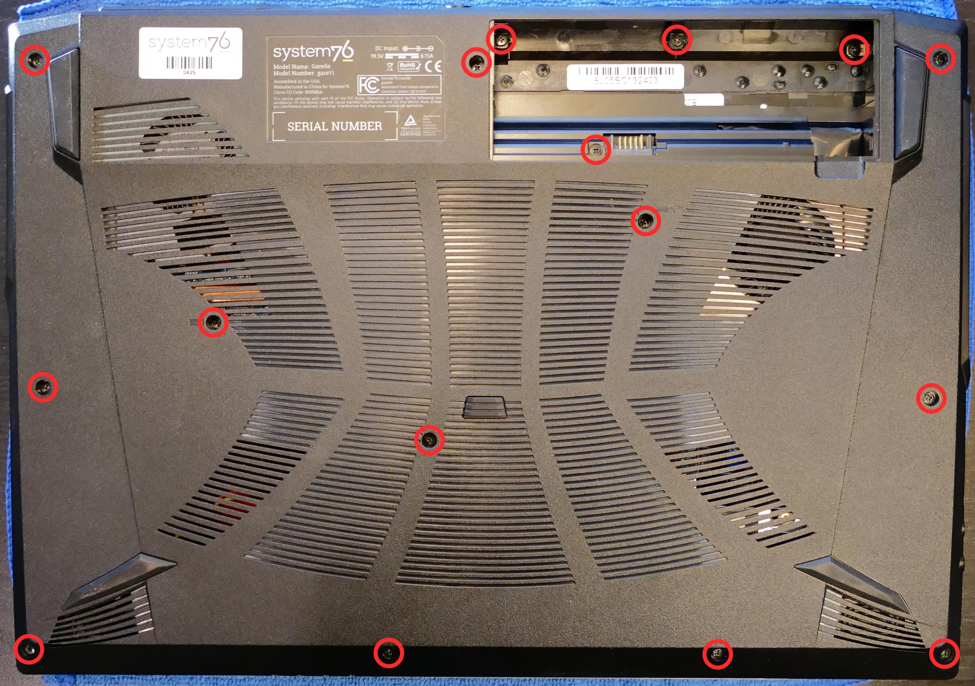
17" version: 12 unmarked screws, 2 keyboard screws, and 3 under-battery screws.
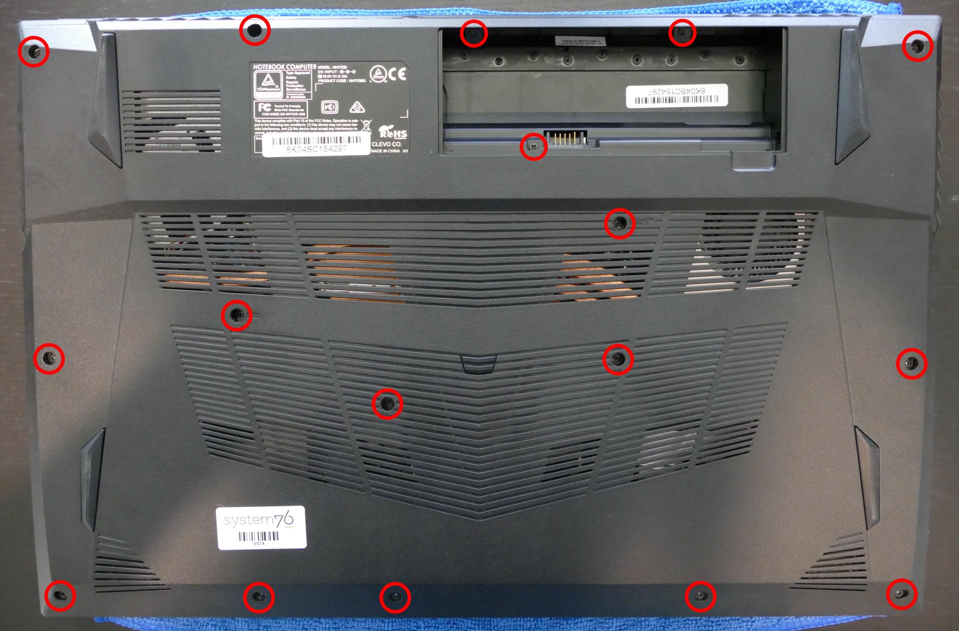
- Lift the bottom cover off, starting from the hinges in the back (it's easiest to pull from just above the battery slot.)
Replacing the RAM:
RAM acts as temporary storage for your computer. More RAM generally provides better performance. If you've purchased new RAM, need to replace your RAM, or are reseating your RAM, follow these steps.
Tools required: Cross-head (Phillips) screwdriver
Time estimate: 10 minutes
Difficulty: Easy ●
Steps to replace the RAM:
- Follow the steps above to remove the bottom cover.
- Press the small tabs on both sides of the RAM simultaneously. The RAM should spring up to an angle.
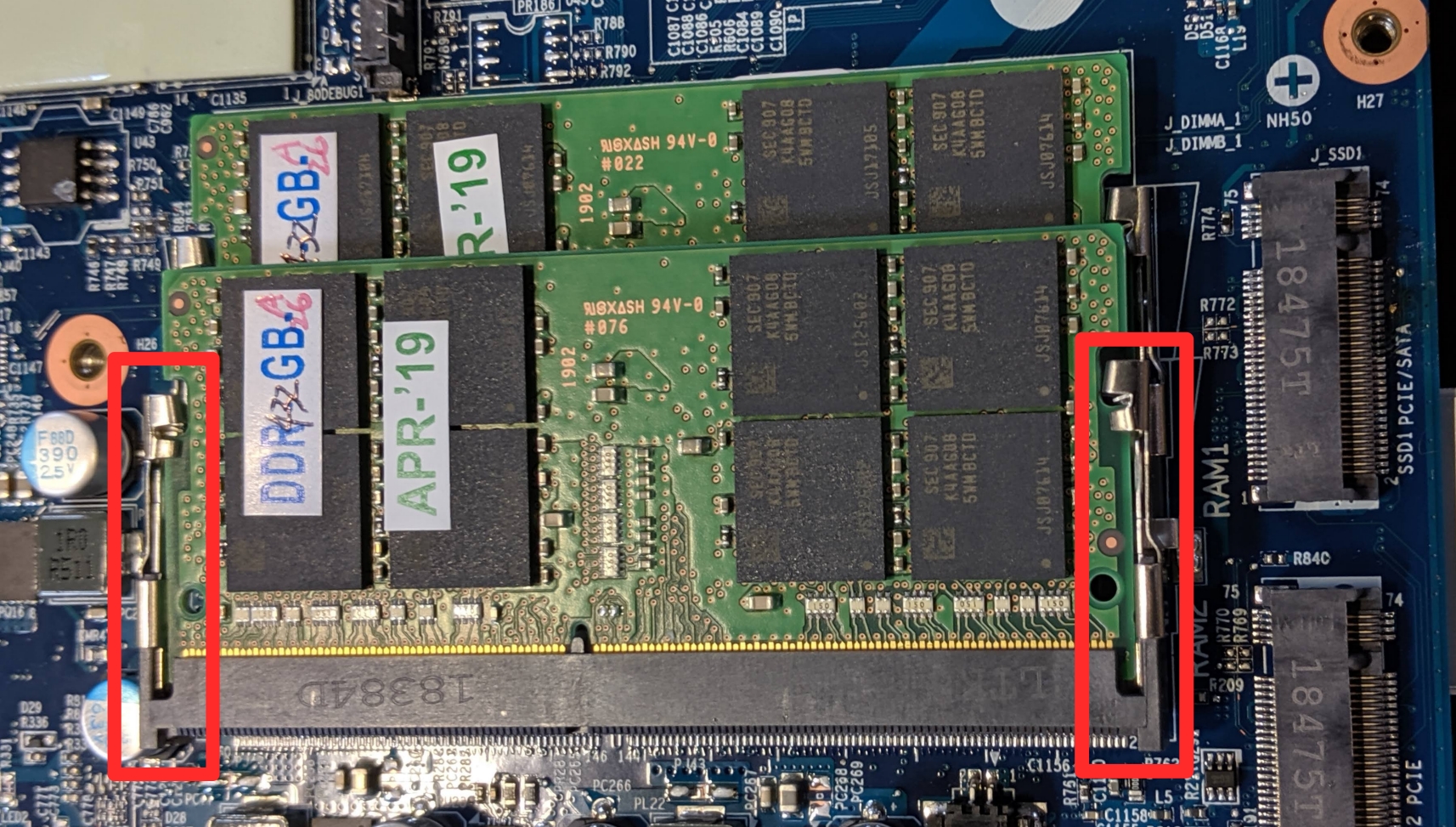
- Remove the RAM from the slot.
- Insert the new RAM (or reseat the existing RAM) by placing it in the keyed slot and pressing down on the RAM until it clicks into place.
Replacing an M.2/NVMe SSD:
This model supports up to two M.2 SSDs. Both M.2 slots are size 2280. The top slot (shown with the yellow box in the image below) supports either SATA III or PCIe NVMe Generation 3, and the bottom slot (orange box) supports only PCIe NVMe Generation 3.
Tools required: Cross-head (Phillips) screwdriver
Time estimate: 10 minutes
Difficulty: Easy ●
Steps to replace the M.2 drive:
- Follow the steps above to remove the bottom cover.
- Locate the M.2 drive (or slot.)

- Unscrew the retainer screw opposite the M.2 slot.
- Remove the existing M.2 drive by pulling it out of the slot.
- Insert the new M.2 drive into the slot and hold it in place.
- Replace the retainer screw.
Replacing a 2.5" storage drive:
This model supports one 2.5" (7mm height) SATA III SSD or hard drive.
Tools required: Cross-head (Phillips) screwdriver
Time estimate: 15 minutes
Difficulty: Medium ●
Steps to replace a 2.5" storage drive:
- Follow the steps above to remove the bottom cover.
- Unscrew the single screw holding the 2.5" drive bracket into the case.

- Slightly lift the loose end of the 2.5" drive and slide it out of the SATA port.
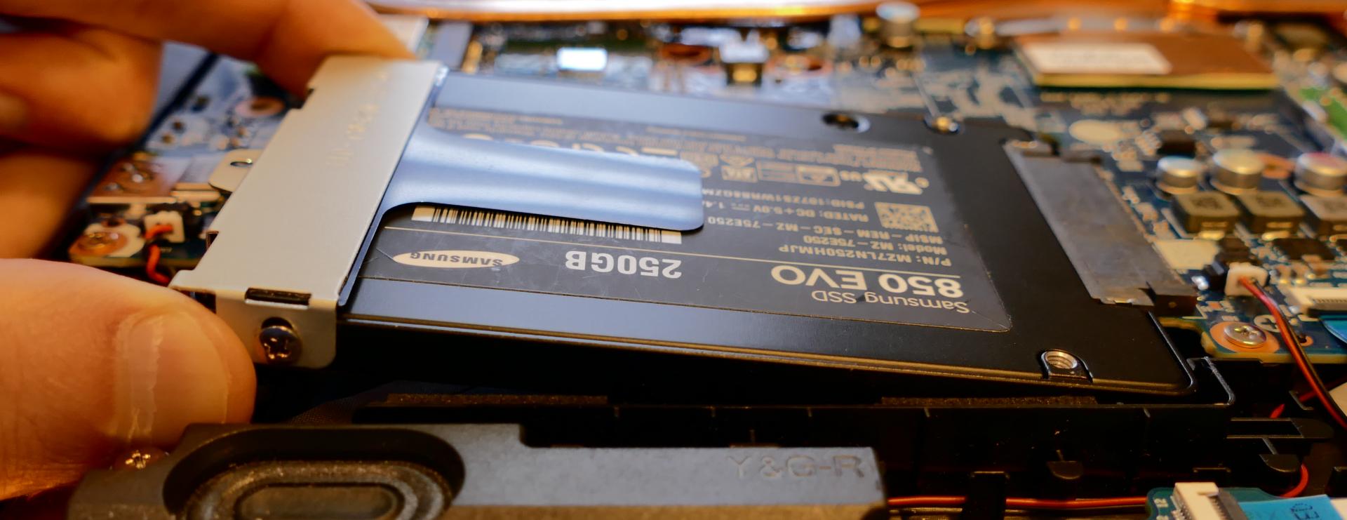
- Unscrew the two screws holding the 2.5" drive into the drive bracket (one on either side.)

- Insert the new 2.5" drive into the drive bracket and replace the two side screws.
- Plug the 2.5" drive into the SATA port and set the drive into the case.
- Screw the drive bracket back into the case.
Replacing the cooling system:
If one of the fans becomes noisy and cleaning it out doesn't fix the issue, you may need a new fan. Contact Support to start a warranty claim or parts purchase.
Depending on your climate and the age of the machine, it may be necessary to apply new thermal paste between the CPU/GPU and the heatsink. Thermal paste helps facilitate effective heat transfer between the CPU/GPU and the cooling equipment. These instructions can also be used in the unlikely event your heatsink needs replacing.
Tools required: Cross-head (Phillips) screwdriver
Time estimate: 20 minutes
Difficulty: High ●
Steps to replace the fans/heatsink/thermal paste:
- Follow the steps above to remove the bottom cover.
- Disconnect both fan cables, removing any tape securing them.
- Locate the CPU heatsink screws.
- Remove the screws, starting with #1, then #2, and continuing until you have removed #11.

- Carefully remove the heatsink/fans from the case.
- Using a paper towel, remove the existing thermal paste. You may also use a small amount of rubbing alcohol to remove excess or difficult-to-remove paste.
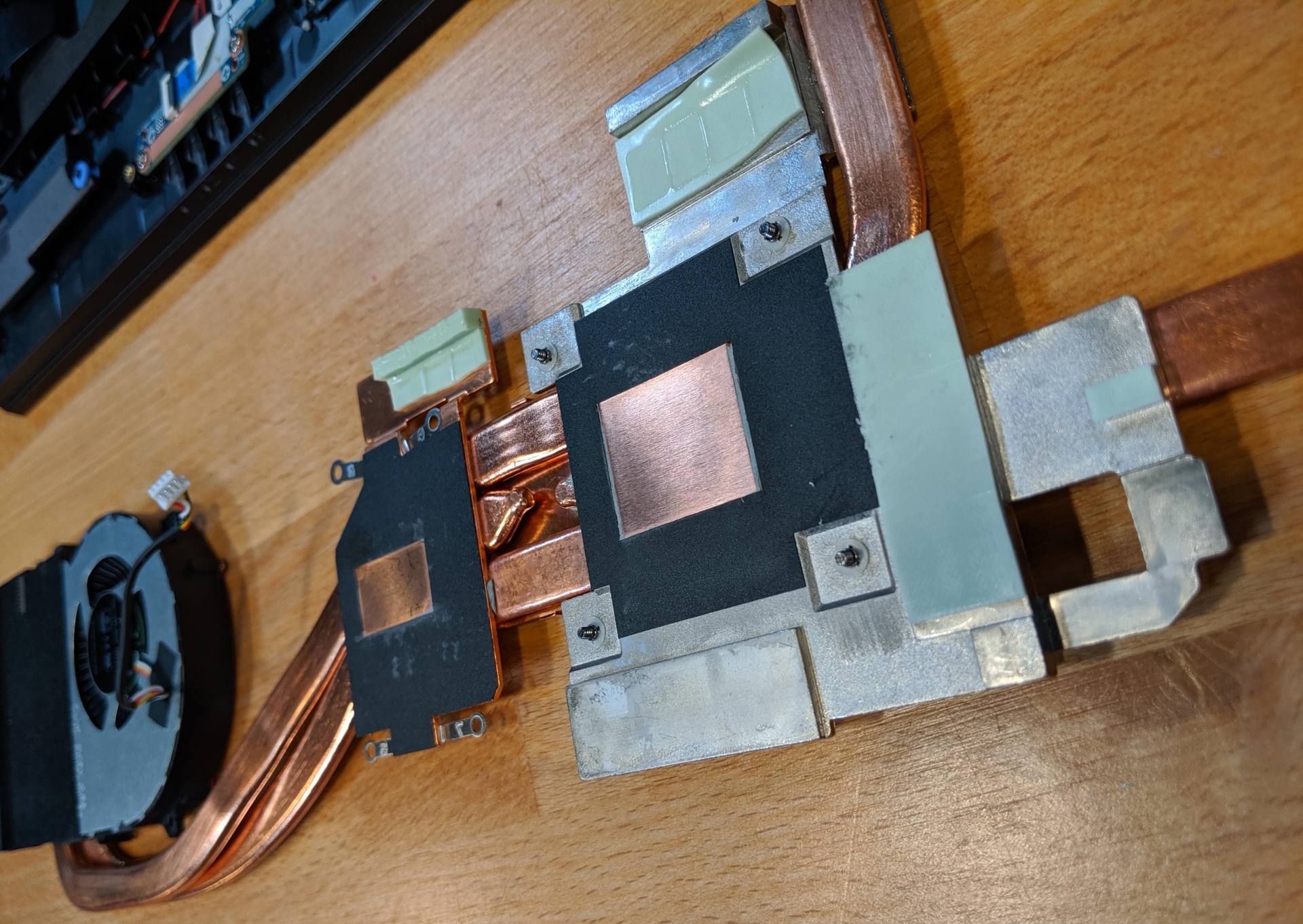
- After cleaning the CPU, GPU, and heatsink, apply a small line of thermal paste directly onto the CPU and GPU core.
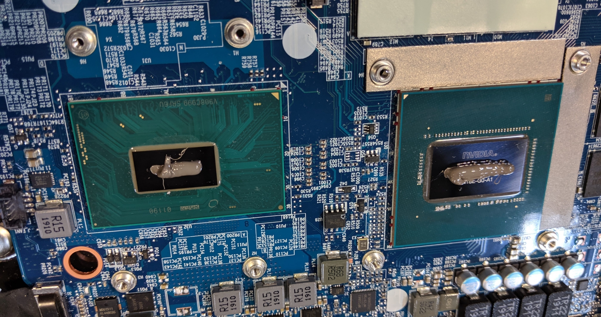
- Carefully replace the heatsink.
- Replace the screws, starting with #1, then #2, and so on until #11. Do not fully tighten until all of the screws have been started, then fully tighten all screws.
- Reconnect the fan cables.
Replacing the CMOS battery:
The CMOS battery supplies power to the Gazelle's CMOS chip. Changes you make to the UEFI firmware settings and the computer's hardware clock are stored on the CMOS. If your Gazelle doesn't boot, you can reset the CMOS to force a low-level hardware reset. If your clock is constantly resetting, it's likely your CMOS battery needs replacing.
Warning (ingestion hazard): Keep batteries out of reach of children. Death or serious injury can occur if ingested. If a battery is suspected to be swallowed or inserted inside any part of the body, seek immediate medical attention. In the US, you can also call the National Battery Ingestion Hotline for guidance: 1 (800) 498-8666
Tools required: Cross-head (Phillips) screwdriver
Time estimate: 10 minutes
Difficulty: Medium ●
Steps to replace the CMOS battery:
- Follow the steps above to remove the bottom cover.
- Locate the CMOS battery, which is connected to the motherboard via a red and black wire, between the 2.5" drive bay and the edge of the computer.

- Unplug the small white connector that connects the CMOS battery to the motherboard. If you are replacing the battery, use a thin plastic tool to pry the battery up from where it's stuck to the case.
- Power up the Gazelle. The system may power itself off and on after initial boot; this is normal behavior when the CMOS has been reset.
- Press Enter at the CMOS/UEFI reset message prompts.
- If the system boots into the BIOS/UEFI setup utility, press F4 to load defaults, then F10 to save and resume normal boot.
Replacing the external battery:
The battery provides primary power whenever the system is unplugged.
The model number for the Gazelle 15's battery is NH50BAT-4; the original part number may be 6-87-NH50S-41C01 or 6-87-NH50S-42D01, depending on the production date of the machine. Third-party battery sellers may list one or both of these numbers, and may offer other compatible part numbers with the same model number. You can also contact System76 to purchase a replacement battery.
Tools required: None
Time estimate: 1 minute
Difficulty: Easy ●
Steps to replace the external battery:
- Place the machine lid-side down.
- Use a soft surface (such as a towel) to avoid scratches.
- Slide the locks that hold the battery to their unlocked positions. (One lock will click into place, while the other is on a spring.)
- Hold back the spring-loaded lock while removing the battery.
- Replace the battery/insert the new battery, then slide the clicking lock to its locked position.
Replacing the wireless card:
Your Gazelle's WiFi and Bluetooth are both handled by the same module. It is a standard M.2 2230 slot with PCIe and USB interfaces (E-key).
Tools required: Cross-head (Phillips) screwdriver
Time estimate: 10 minutes
Difficulty: Medium ●
Steps to replace the WiFi/Bluetooth module:
- Follow the steps above to remove the bottom cover.
- Locate the wireless module.

- Gently remove the two antennas by pulling them up and away from the wireless card.
- Remove the retaining screw opposite the M.2 slot.
- Remove the wireless card from the M.2 slot.
- Insert the new wireless card into the M.2 slot.
- Replace the retaining screw.
- Attach the two antennas by aligning the circular fitting and pressing onto the wireless card. The connector will snap into place. Use caution when attaching the connectors; the pins can bend, break, or snap.
Jackal Pro 1U (jacp1-b1)
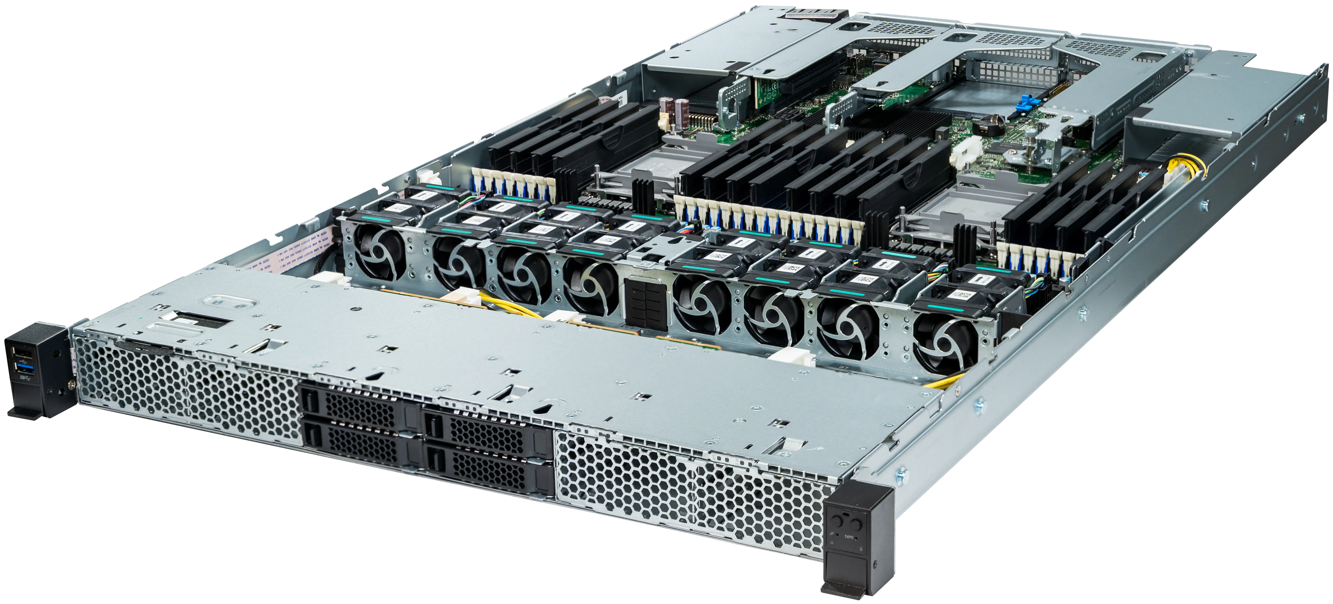
The System76 Jackal Pro 1U is a rack-mounted server. The B1 model code indicates the first revision based on an Intel platform. This model has the following specifications:
- Chassis
- CPU options
- Supports 2x Intel Xeon Scalable 3rd-generation processors
- Memory
- Up to 8192GB (32x256GB) ECC DDR4 @ 3200 MHz
- Storage
- Front:
- 4x 2.5" SATA/SAS hot-swappable HDD/SSD bays
- Internal:
- 2x M.2 PCIe NVMe Gen 3 slots
- Front:
- Networking
- 2x 1GbE LAN ports
- Expansion
- Riser Slot 1: PCIe 4.0, 32 lanes
- Preinstalled riser card: x16 slot
- Riser Slot 2: PCIe 4.0, 32 lanes
- Preinstalled riser card options:
- Option 1: x16 slot
- Option 2: x16 slot and x8 slot
- Preinstalled riser card options:
- Riser Slot 3: PCIe 4.0, 16 lanes
- Preinstalled riser card: two x8 slots
- Riser Slot 1: PCIe 4.0, 32 lanes
- Front I/O
- 1x USB 3.0
- 1x USB 2.0
- 1x Power button with LED
- 1x ID button with LED
- 1x Cold reset button (tool required)
- 1x NMI button (tool required)
- 1x System status LED
- 1x Drive activity LED
- Back I/O
- 3x USB 3.0
- 1x VGA
- 2x RJ45 (Ethernet)
- 1x Management LAN
- 1x RJ45 (Serial)
- Power Supply
- 1x 1300W High Efficiency PSU
- Optional second (redundant) PSU
- 1x 1300W High Efficiency PSU
- Dimensions
- 43.8cm x 78.1cm x 4.3cm, 17.24kg
Jackal Pro 2U (jacp2-b1)
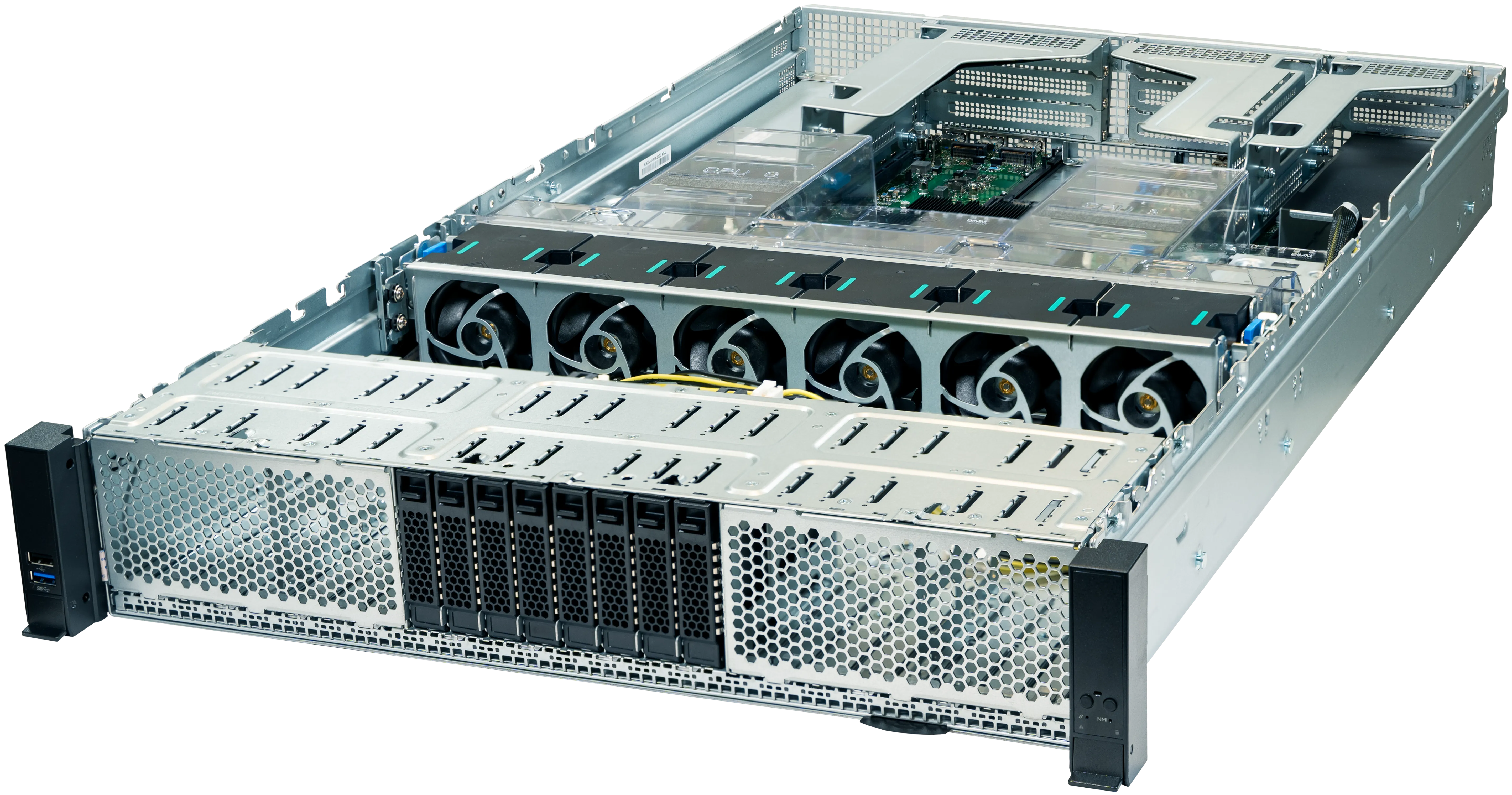
The System76 Jackal Pro 2U is a rack-mounted server. The B1 model code indicates the first revision based on an Intel platform. This model has the following specifications:
- Chassis
- CPU options
- Supports 2x Intel Xeon Scalable 3rd-generation processors
- Memory
- Up to 8192GB (32x256GB) ECC DDR4 @ 3200 MHz
- Storage
- Front:
- 24x 2.5" SATA/SAS hot-swappable HDD/SSD bays
- Internal:
- 2x M.2 PCIe NVMe Gen 3 slots
- Front:
- Networking
- 2x 1GbE LAN ports
- Expansion
- Riser Slot 1: PCIe 4.0, 32 lanes
- Preinstalled riser card options:
- Option 1: one x16 slot and two x8 slots
- Option 2: two x16 slots
- Preinstalled riser card options:
- Riser Slot 2: PCIe 4.0, 32 lanes
- Preinstalled riser card options:
- Option 1: one x16 slot and two x8 slots
- Option 2: two x16 slots
- Preinstalled riser card options:
- Riser Slot 3: PCIe 4.0, 16 lanes
- Preinstalled riser card: two x8 slots
- Riser Slot 1: PCIe 4.0, 32 lanes
- Front I/O
- 1x USB 3.0
- 1x USB 2.0
- 1x Power button with LED
- 1x ID button with LED
- 1x Cold reset button (tool required)
- 1x NMI button (tool required)
- 1x System status LED
- 1x Drive activity LED
- Back I/O
- 3x USB 3.0
- 1x VGA
- 2x RJ45 (Ethernet)
- 1x Management LAN
- 1x RJ45 (Serial)
- Power Supply
- 1x 1300W High Efficiency PSU
- Optional second (redundant) PSU
- 1x 1300W High Efficiency PSU
- Dimensions
- 43.9cm x 71.2cm x 8.9cm, 17.24kg
Launch (launch_2)
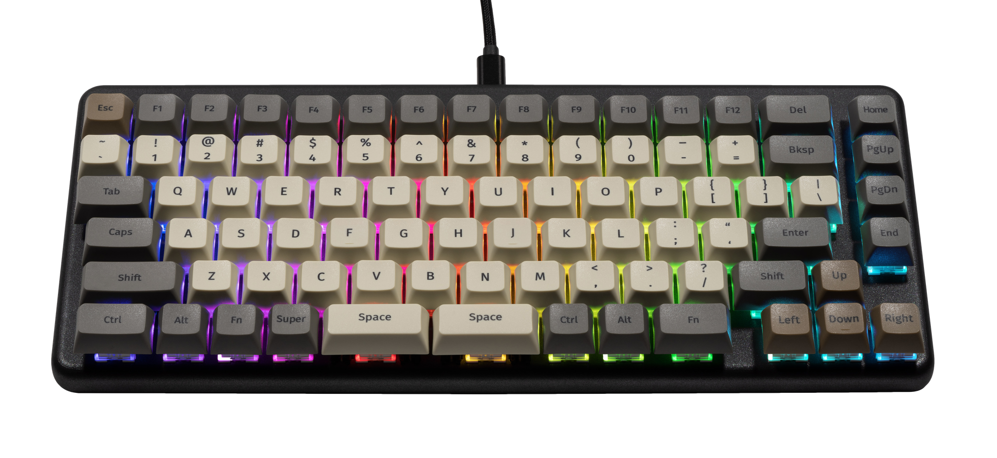
The System76 Launch is a configurable keyboard with the following specifications:
- Chassis
- Open-source milled chassis design
- Magnetically-attachable 15-degree angle lift bar
- Electronics
- Open-source PCB design
- Individually addressable RGB LED backlighting
- N-key rollover
- Sockets and Switches
- Kailh MX hot swap sockets
- Default switch options:
- NovelKeys x Kailh Box Jade
- NovelKeys x Kailh Box Royal
- Kailh Box Silent Brown
- Kailh Box Silent Pink
- Keycaps
- PBT plastic
- Dye sublimated legend
- XDA profile
- Sizes:
- 3x 2U keycaps (both
Spacebars and leftShift)- All three 2U caps use plate-mount stabilizers
- 8x 1.5U keycaps (
Tab,Caps, leftCtrl, rightFn, rightShift,Enter,Bksp, andDel) - 73x 1U keycaps
- 3x 2U keycaps (both
- Layout
- Modified ANSI US QWERTY
- Custom Configurations
- Customize layout and lighting in firmware with the System76 Keyboard Configurator
- Available on Linux, Windows, and macOS
- Integrated Hub
- 2x USB 3.2 Gen 1 Type-C
- 2x USB 3.2 Gen 1 Type-A
- Firmware
- Included cables:
- 1x USB Type-C to USB Type-C
- 1x USB Type-C to USB Type-A
- Dimensions
- 30.83cm x 13.51cm x 3.061cm, 948g
Launch (External Overview)
Top overview:

Back overview:

Box contents overview:

Launch (Customization & Repairs)
The Launch Configurable Keyboard can be customized and personalized in a variety of ways. It is recommended to unplug all USB cables and devices from your Launch before changing keycaps or switches.
- Connecting and using Launch
- Removing and installing keycaps
- Removing and installing switches
- Removing the PCB
Connecting and using Launch:

- Connect the USB-C side of either the USB-C/USB-C or USB-C/USB-A cable to the Launch's center USB-C port, shown above.
- Connect the other side of the cable to your computer.
- Connect any other USB devices to the four downstream USB ports on either side of the Launch.
Removing and installing keycaps:
Launch uses only three sizes of uniform profile keycaps, which allows for a high degree of customization. Any two keycaps of the same size can be swapped on the keyboard, and several extras are included in the box.
Tools required: Keycap puller
Time estimate: 20 minutes (to replace all keycaps)
Difficulty: Easy ●
Steps to remove a keycap:
- Separate the two wire loops of the keycap puller and place them around two opposite corners of the keycap.
- The keycap puller can be partially inserted over the sides of the key first, then twisted to go over the corners.


- Pull slowly but firmly (directly away from the keyboard) until the keycap slides off of the switch's stem.

Removing larger keycaps:
- The included keycap puller works on all three of Launch's keycap sizes.
- The three 2U keycaps (both space bars and left shift) have stabilizers, so be sure to pull both sides evenly.
- These 2U keycaps take slightly more pulling force than the rest of the keycaps.

Steps to install a keycap:
- Position the keycap on top of the switch.
- Press the keycap down firmly until it's fully on the switch.
- The keycap will be held onto the switch by friction.
- The 2U keycaps with stabilizers require slightly more pressure to install.

Removing and installing switches:
Because Launch uses Kailh hot swap sockets, key switches can be removed and installed without soldering.
If you are changing all of the switches in your Launch, it is recommended to completely remove the PCB, install the switches into the top case without the PCB, then install the PCB into the case and onto the switch pins. This makes switch installation easier and reduces the likelihood of bending switch pins or damaging the PCB.
If you are installing new switches, ensure that the switches you're installing are compatible with surface-mount (SMD) LEDs.
Tools required: MX-style switch puller
Time estimate: ~1 minute per switch
Difficulty: Medium ●
Steps to remove a switch:
- Remove the keycap on the switch you wish to remove.
- Place the two tongs of the switch removal tool into the switch's locking tabs on the top and bottom edges of the switch.

- Pinch the tongs together to release the switch's locking clips from the chassis.
- Pull the switch upwards out of the socket.
- The switch's locking tabs can sometimes catch on the edges of the chassis cutouts. If the switch feels stuck, remove the tool and press the switch back down into place, then try removing it again.
- Switches take more force to remove than keycaps.

Steps to install a switch:
- Make sure the switch's pins are straight.
- If either of the pins is bent, gently bend it back into place.
- Caution: Attempting to install a switch with bent pins may damage the PCB and/or switch.

- Orient the switch so the clear LED window aligns with the LED on the PCB, near the top of the socket.

- Place the switch straight into the plate.
- Caution: Forcing the pins into the hot swap socket if the pins are not properly aligned could damage the PCB and/or switch.
- If you feel excessive resistance, pull the switch out, double-check that the pins are straight, and try installing the switch again.
- Once you feel the pins plug into the hot swap socket, press the switch down with more force to snap it into place within the chassis.

Removing the PCB:
Tools required: Keycap puller, MX-style switch puller, and cross-head (Phillips) screwdriver
Time estimate: 50 minutes
Difficulty: High ●
If the PCB in your Launch becomes damaged and needs to be replaced, or if you are changing all of the switches on the PCB, it can be removed and replaced using these instructions.
Steps to remove the PCB:
- Remove all of the keycaps and all of the switches.
- The 2U stabilizers do not need to be removed.


- Turn the keyboard over and remove the five bottom panel screws.
- The screws are set into adapters that may or may not come out with the screws.

- Remove the bottom panel.
- If the magnetic lift bar is installed, it can be used as a handle.

- Push the PCB up out of the chassis through one of the switch holes, then lift the PCB out of the chassis.
- To avoid the USB-C port catching on the chassis, push through one of the bottom row switch holes and lift the bottom edge of the PCB first.

Steps to install the PCB:
- Install all of the switches into the chassis.
- The switches can also be installed after installing the PCB, but installing the switches first is recommended because it reduces the risk of individual bent pins damaging the PCB or switches during installation.
- Make sure the switches are in the correct orientation with the LED window at the top.
- The switches are not specific to their key/hole.

- Turn the chassis over and check that all of the switch pins are straight.
- Look down the rows of pins from the sides of the chassis to identify any bent pins.
- If any of the pins are bent when installing the PCB, the switch or the PCB may be damaged.
- In the image below, the pin marked with a red arrow is an example of a pin that is bent and needs to be straightened.

- Carefully line up the PCB with the switch pins and place it in the chassis, starting with the USB-C ports on the top edge.
- Evenly press the PCB down until all of the switch pins are fully seated in their sockets.
- It may help to pick up the keyboard and pinch to press both the PCB and the switches at the same time.
- If you feel excessive resistance, stop, remove the PCB, and ensure that all of the switch pins are lined up.
- The switch pins can be seen from the back of the sockets when they are fully seated, highlighted below.

- Install the bottom cover and its four screws, flip the keyboard over, and put all of the keycaps back on.
- If any of the oval steel inserts came loose from the bottom cover, put them back into place before reinstalling the bottom cover.
- The steel inserts are held in with glue, but are also held in place magnetically if the magnetic lift bar is installed. They can be re-glued with CA glue.
- If any of the oval steel inserts came loose from the bottom cover, put them back into place before reinstalling the bottom cover.
Launch (launch_1)

The System76 Launch is a configurable keyboard with the following specifications:
- Chassis
- Open-source milled chassis design
- Magnetically-attachable 15-degree angle lift bar
- Electronics
- Open-source PCB design
- Individually addressable RGB LED backlighting
- N-key rollover
- Sockets and Switches
- Kailh MX hot swap sockets
- Default switch options:
- NovelKeys x Kailh Box Jade
- NovelKeys x Kailh Box Royal
- Kailh Box Silent Brown
- Kailh Box Silent Pink
- Keycaps
- PBT plastic
- Dye sublimated legend
- XDA profile
- Sizes:
- 3x 2U keycaps (both
Spacebars and leftShift)- All three 2U caps use plate-mount stabilizers
- 8x 1.5U keycaps (
Tab,Caps, leftCtrl, rightFn, rightShift,Enter,Bksp, andDel) - 73x 1U keycaps
- 3x 2U keycaps (both
- Layout
- Modified ANSI US QWERTY
- Custom Configurations
- Customize layout and lighting in firmware with the System76 Keyboard Configurator
- Available on Linux, Windows, and macOS
- Integrated Hub
- 2x USB 3.2 Gen 2 Type-C
- 2x USB 3.2 Gen 2 Type-A
- Firmware
- Included cables:
- 1x USB Type-C to USB Type-C
- 1x USB Type-C to USB Type-A
- Dimensions
- 30.9cm x 13.6cm x 3.3cm, 948g
Launch (External Overview)
Top overview:
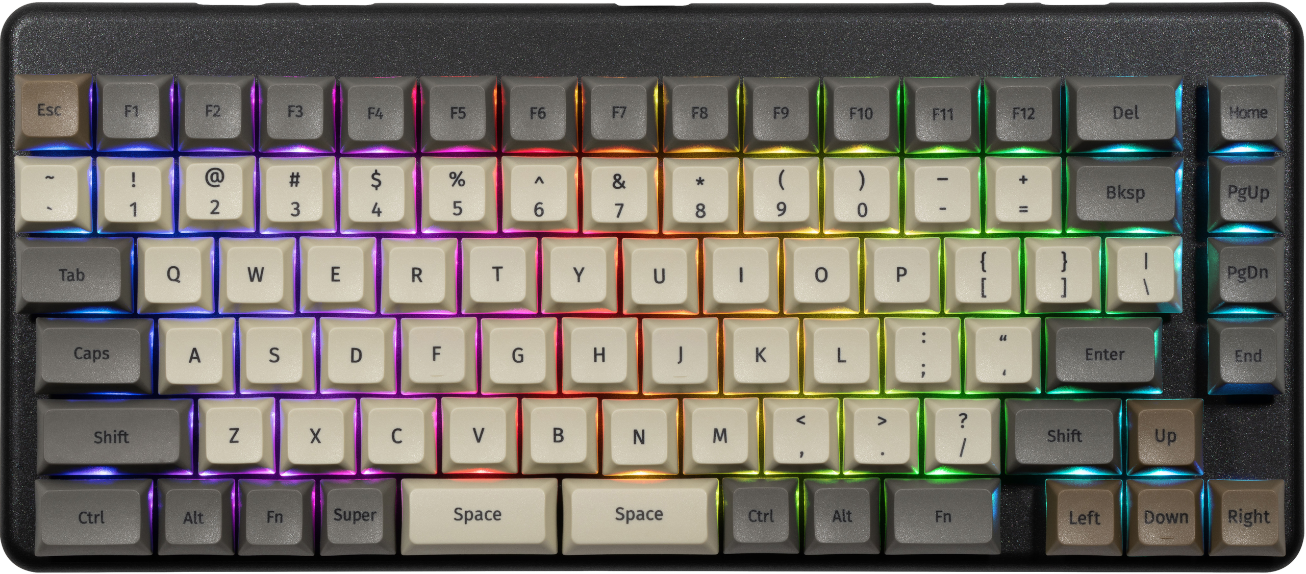
Back overview:

Box contents overview:
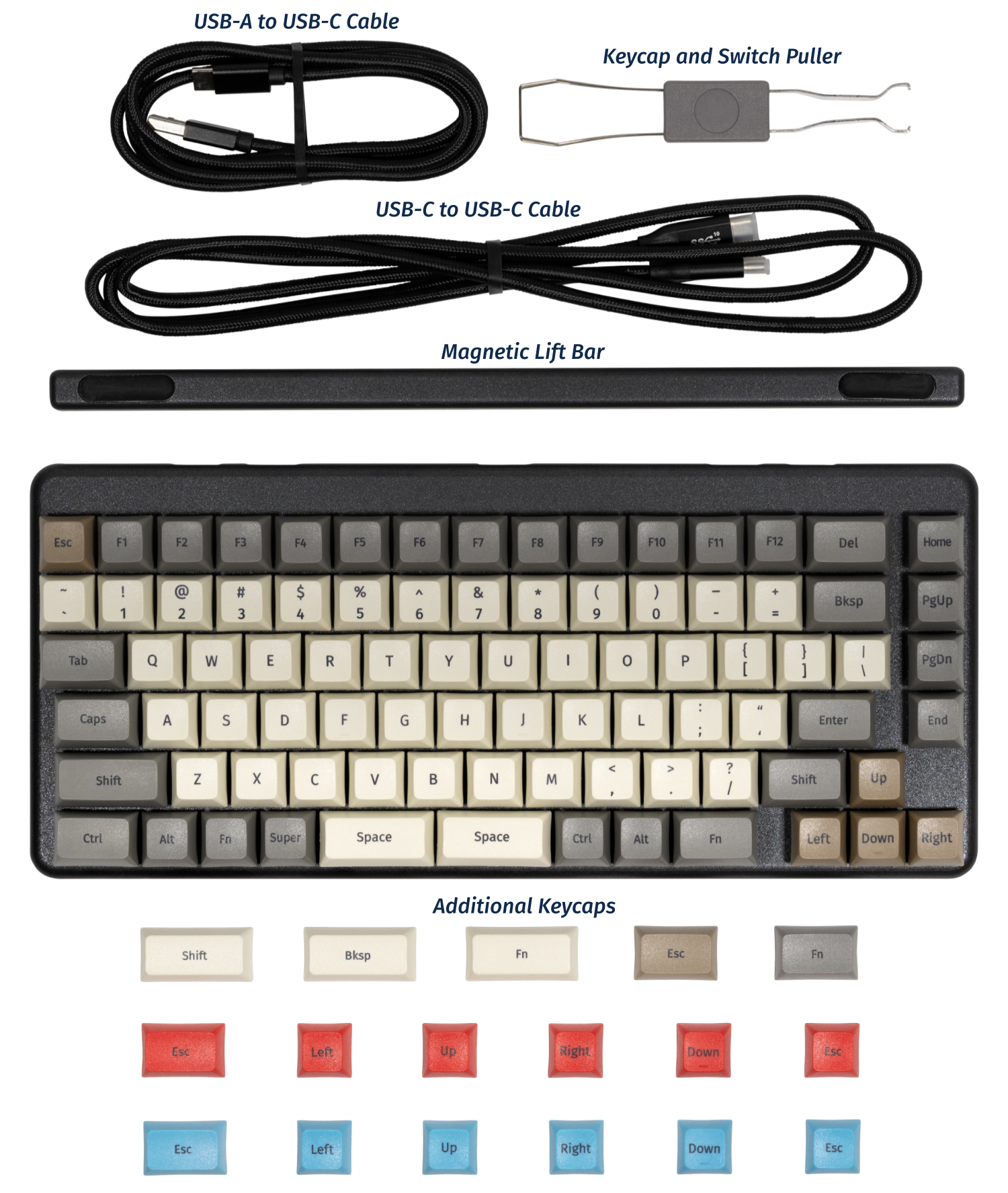
Launch (Customization & Repairs)
The Launch Configurable Keyboard can be customized and personalized in a variety of ways. It is recommended to unplug all USB cables and devices from your Launch before changing keycaps or switches.
- Connecting and using Launch
- Removing and installing keycaps
- Removing and installing switches
- Removing the PCB
Connecting and using Launch:

- Connect the USB-C side of either the USB-C/USB-C or USB-C/USB-A cable to the Launch's center USB-C port, shown above.
- Connect the other side of the cable to your computer.
- Connect any other USB devices to the four downstream USB ports on either side of the Launch.
Removing and installing keycaps:
Launch uses only three sizes of uniform profile keycaps, which allows for a high degree of customization. Any two keycaps of the same size can be swapped on the keyboard, and several extras are included in the box.
Tools required: Keycap puller
Time estimate: 20 minutes (to replace all keycaps)
Difficulty: Easy ●
Steps to remove a keycap:
- Separate the two wire loops of the keycap puller and place them around two opposite corners of the keycap to be removed.
- Pull slowly but firmly on the keycap until it slides off the switch's stem.
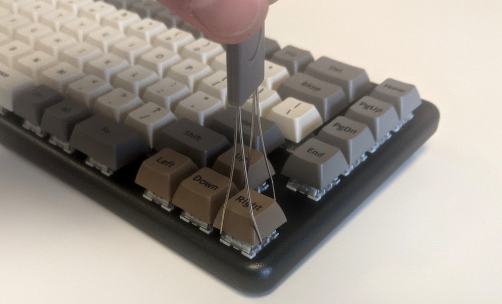
Notes about removing larger keycaps:
- The included keycap puller works on all three of Launch's keycap sizes.
- The three 2U keycaps (both space bars and left shift) have stabilizers, so be sure to pull both sides evenly.
- These 2U keycaps take slightly more pulling force than the rest of the keycaps.
Steps to install a keycap:
- Position the keycap on the switch.
- Press the keycap down firmly until it's fully on the switch. The cap will friction-fit onto the switch stem.
- The 2U keycaps with stabilizers require slightly more pressure to install.
Removing and installing switches:
Since Launch uses Kailh hot swap sockets, key switches can be removed and installed without soldering.
If you are changing all of the switches in your Launch, it is recommended to completely remove the PCB, install the switches into the top case without the PCB, then install the PCB into the case and onto the switch pins. This makes switch installation easier and makes bending switch pins or damaging the PCB much less likely.
If you are installing new switches, ensure that the switches you're installing are compatible with surface-mount (SMD) LEDs.
Tools required: MX-style switch puller
Time estimate: ~1 minute per switch
Difficulty: Medium ●
Steps to remove a switch:
- Remove the keycap on the switch you wish to remove.
- Place the two tongs of the switch removal tool into the switch's locking tabs on the top and bottom edges of the switch.
- The hooks should squeeze the white tabs inwards and hook under the switch's clear plastic top housing.
- Slightly pinch the tongs together to help release the switch's locking clips from the cutout in the top case.
- Pull the switch upwards out of the socket.
- The switch's locking tabs can sometimes bind on the edges of the top case. If the switch feels stuck, remove the tool and press the switch back down into place, then try removing it again.
- Switches take more force to remove than keycaps.
Steps to install a switch:
- Make sure the switch's pins are straight.
- The pins must plug into the socket, and they'll miss their slots if they are bent.
- Orient the switch so the clear LED shine-through window aligns with the LED on the PCB, near the top of the socket.
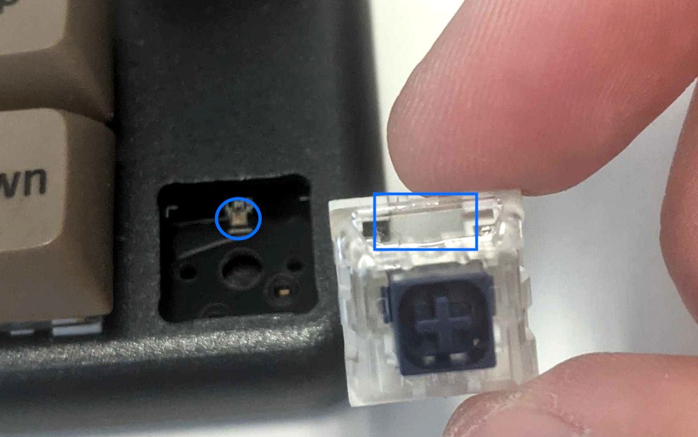
- Place the switch straight into the plate.
- Caution: Forcing the pins into the hot swap socket could damage the PCB.
- You should be able to feel whether the pins are plugging into the socket correctly.
- If you feel excessive resistance, pull the switch out, double-check that the pins are straight, and try installing the switch again.
- Once you feel the pins plug into the hot swap socket, press the switch down with more force to snap it into place within the chassis.
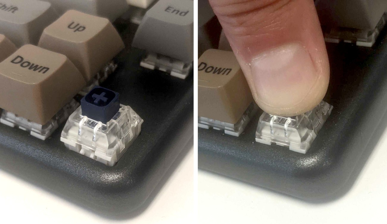
Removing the PCB:
Tools required: Keycap puller, MX-style switch puller, and cross-head (Phillips) screwdriver
Time estimate: 50 minutes
Difficulty: High ●
If the PCB in your Launch becomes damaged and needs to be replaced, or if you are changing all of the switches on the PCB, it can be removed and replaced using these instructions.
Steps to remove the PCB:
- Remove all of the keycaps and all of the switches.
- Turn the keyboard over and remove the eight bottom panel screws.
- Remove the bottom panel.
- Lifting the bottom panel out of the chassis may be easier with the magnetic lift bar installed.

- Push the PCB up out of the chassis through one of the switch holes, then lift the PCB out of the chassis.
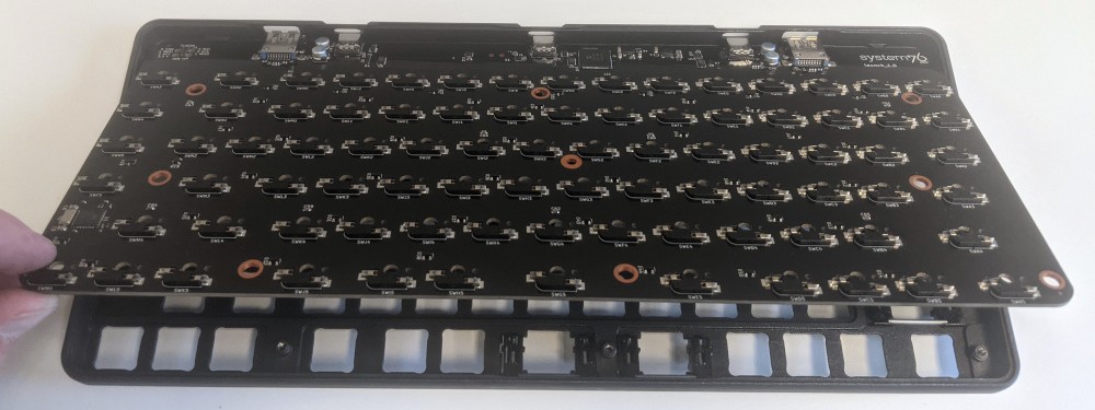
Steps to install the PCB:
- Install all of the switches into the chassis.
- Installing switches with the PCB removed is much easier since you don't have to worry about aligning the pins individually.
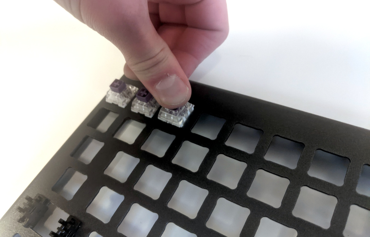
- Turn the chassis over and check that all of the switch pins are straight.
- Look down the rows of pins from the sides of the chassis to identify any bent pins.
- If any of the pins are bent when installing the PCB, the switch or the PCB may be damaged.
- In the image below, the pin highlighted red is an example of a pin that is bent and needs to be straightened.
- Carefully line up the PCB with the switch pins and place it in the chassis.
- It may be easiest to insert the top edge first since the USB-C ports need to align with the port cutouts in the chassis.
- If all of the switch pins feel lined up, press the PCB down little by little until all of the switch pins are fully seated in their sockets.
- The switch pins can be seen coming up through the sockets when they are fully seated (circled in green below).
- Install the bottom cover and its eight screws, flip the keyboard over, and put all of the keycaps back on.
Launch Heavy (launch_heavy_1)

The System76 Launch Heavy is a configurable keyboard with the following specifications:
- Chassis
- Open-source milled chassis design
- Dual magnetically-attachable 15-degree angle lift bars
- Electronics
- Open-source main PCB design
- Revision 2.0
- Open-source numpad PCB design
- Revision 1.1
- Individually addressable RGB LED backlighting
- N-key rollover
- Open-source main PCB design
- Sockets and Switches
- Kailh MX hot swap sockets
- Default switch options:
- NovelKeys x Kailh Box Jade
- NovelKeys x Kailh Box Royal
- Kailh Box Silent Brown
- Kailh Box Silent Pink
- Keycaps
- PBT plastic
- Dye sublimated legend
- XDA profile
- Sizes:
- 6x 2U keycaps (both
Spacebars, leftShift, numpad0, numpad+, and numpadEnter)- All six 2U caps use plate-mount stabilizers
- 8x 1.5U keycaps (
Tab,Caps, leftCtrl, rightFn, rightShift,Enter,Bksp, andDel) - 91x 1U keycaps
- 6x 2U keycaps (both
- Layout
- Modified ANSI US QWERTY
- Custom Configurations
- Customize layout and lighting in firmware with the System76 Keyboard Configurator
- Available on Linux, Windows, and macOS
- Integrated Hub
- 2x USB 3.2 Gen 1 Type-C
- 2x USB 3.2 Gen 1 Type-A
- Firmware
- Included cables:
- 1x USB Type-C to USB Type-C
- 1x USB Type-C to USB Type-A
- Dimensions
- 39.40cm x 13.51cm x 3.03cm, 1315.42g
Launch Heavy (External Overview)
Top overview:

Back overview:

Box contents overview:

Launch Heavy (Customization & Repairs)
The Launch Heavy Configurable Keyboard can be customized and personalized in a variety of ways. It is recommended to unplug all USB cables and devices from your Launch Heavy before changing keycaps or switches.
- Connecting and using Launch Heavy
- Removing and installing keycaps
- Removing and installing switches
- Removing the PCBs
Connecting and using Launch Heavy:
- Connect the USB-C side of either the USB-C/USB-C or USB-C/USB-A cable to the Launch Heavy's center USB-C port.

- Connect the other side of the cable to your computer.
- Connect any other USB devices to the four downstream USB ports on either side of the Launch Heavy.
Removing and installing keycaps:
Launch Heavy uses only three sizes of uniform profile keycaps, which allows for a high degree of customization. Any two keycaps of the same size can be swapped on the keyboard, and several extras are included in the box.
Tools required: Keycap puller
Time estimate: 25 minutes (to replace all keycaps)
Difficulty: Easy ●
Steps to remove a keycap:
- Separate the two wire loops of the keycap puller and place them around two opposite corners of the keycap.
- The keycap puller can be partially inserted over the sides of the key first, then twisted to go over the corners.


- Pull slowly but firmly (directly away from the keyboard) until the keycap slides off of the switch's stem.

Removing larger keycaps:
- The included keycap puller works on all three of Launch Heavy's keycap sizes.
- The six 2U keycaps (both
Spacebars, leftShift, numpad0, numpad+, and numpadEnter) have stabilizers, so be sure to pull both sides evenly.- These 2U keycaps take slightly more pulling force than the rest of the keycaps.

Removing vertical keycaps:
- For the
launch_heavy_1.1revision numpad PCB, when removing vertical 2U keycaps (numpadEnterand numpad+), the switch will come out of the socket with the keycap.

- If you are not replacing the switch, remove it from the keycap and install it back into the keyboard before putting on the new keycap.
Steps to install a keycap:
- Position the keycap on top of the switch.
- Press the keycap down firmly until it's fully on the switch.
- The keycap will be held onto the switch by friction.
- The 2U keycaps with stabilizers require slightly more pressure to install.

Removing and installing switches:
Launch Heavy uses Kailh hot swap sockets, so key switches can be removed and installed without soldering.
If you are changing all of the switches in your Launch Heavy, it is recommended to completely remove the PCBs, install the switches into the top case without the PCB, then install the PCBs into the case and onto the switch pins. This makes switch installation easier and reduces the likelihood of bending switch pins or damaging the PCBs.
If you are installing new switches, ensure that the switches you're installing are compatible with surface-mount (SMD) LEDs.
Tools required: MX-style switch puller
Time estimate: ~1 minute per switch
Difficulty: Medium ●
Steps to remove a switch:
- Remove the keycap on the switch you wish to remove.
- Place the two tongs of the switch removal tool into the switch's locking tabs on the top and bottom edges of the switch.

- Pinch the tongs together to release the switch's locking clips from the chassis.
- Pull the switch upwards out of the socket.
- The switch's locking tabs can sometimes catch on the edges of the chassis cutouts. If the switch feels stuck, remove the tool and press the switch back down into place, then try removing it again.
- Switches take more force to remove than keycaps.

Steps to install a switch:
- Make sure the switch's pins are straight.
- If either of the pins is bent, gently bend it back into place.
- Caution: Attempting to install a switch with bent pins may damage the PCB and/or switch.

- Orient the switch so the clear LED window aligns with the LED on the PCB, near the top of the socket.

- Place the switch straight into the plate.
- Caution: Forcing the pins into the hot swap socket if the pins are not properly aligned could damage the PCB and/or switch.
- If you feel excessive resistance, pull the switch out, double-check that the pins are straight, and try installing the switch again.
- Once you feel the pins plug into the hot swap socket, press the switch down with more force to snap it into place within the chassis.

Removing the PCBs:
Tools required: Keycap puller, MX-style switch puller, and cross-head (Phillips) screwdriver
Time estimate: 50 minutes
Difficulty: High ●
If either of the PCBs in your Launch Heavy become damaged and need to be replaced, or if you are changing all of the switches in the keyboard, they can be removed and replaced using these instructions. The two PCBs are joined by a 100mm long, 20 pin, 0.5mm pitch FPC cable.
Steps to remove the PCBs:
- Remove all of the keycaps and all of the switches.
- The 2U stabilizers do not need to be removed.


- Turn the keyboard over and remove the eight bottom panel screws.
- The screws are set into adapters that may or may not come out with the screws.

- Remove the bottom panel.
- If the magnetic lift bars are installed, they can be used as handles.

- Disconnect and remove the flat ribbon cable between the main PCB (
launch 2.0) and the numpad PCB (launch_heavy 1.1).- Slide the black latches away from the white connectors to free the cable.

- Push each PCB up out of the chassis through one of the switch holes, then lift each PCB out of the chassis, one at a time.
- For the main board, to avoid the USB-C port catching on the chassis, push through one of the bottom row switch holes and lift the bottom edge of the PCB first.

Steps to install the PCBs:
- Install all of the switches into the chassis.
- The switches can also be installed after installing the PCBs, but installing the switches first is recommended because it reduces the risk of individual bent pins damaging the PCBs or switches during installation.
- Make sure the switches are in the correct orientation with the LED window at the top.
- The switches are not specific to their key/hole.

- Turn the chassis over and check that all of the switch pins are straight.
- Look down the rows of pins from the sides of the chassis to identify any bent pins.
- If any of the pins are bent when installing the PCBs, the switch or corresponding PCB may be damaged.
- In the image below, the pin marked with a red arrow is an example of a pin that is bent and needs to be straightened.

- Carefully line up the main PCB with the switch pins and place it in the chassis, starting with the USB-C port on the top edge.
- Evenly press the PCB down until all of the switch pins are fully seated in their sockets.
- It may help to pick up the keyboard and pinch to press both the PCB and the switches at the same time.
- If you feel excessive resistance, stop, remove the PCB, and ensure that all of the switch pins are lined up.
- The switch pins can be seen from the back of the sockets when they are fully seated, highlighted below.

- Repeat the previous step for the numpad PCB.
- Insert the ribbon cable into the white connector on both PCBs, then slide the black latches shut.
- The ribbon should bend downwards from the connectors, so as not to obstruct the screw hole in the numpad PCB.
- Install the bottom cover and its four screws, flip the keyboard over, and put all of the keycaps back on.
- If any of the oval steel inserts came loose from the bottom cover, put them back into place before reinstalling the bottom cover.
- The steel inserts are held in with glue, but are also held in place magnetically if the magnetic lift bar is installed. They can be re-glued with CA glue.
- If any of the oval steel inserts came loose from the bottom cover, put them back into place before reinstalling the bottom cover.
Lemur Pro (lemp12)
The System76 Lemur Pro is a laptop with the following specifications:
- CPU
- Supports Intel 13th Generation (Raptor Lake) CPUs
- BIOS
- Flash chip options:
- GigaDevice GD25B256EYIG
- Macronix MX25L25673G
- ...or other equivalent
- WSON-8 form factor
- Programmed with System76 Open Firmware
- Flash chip options:
- EC
- ITE IT5570E
- Programmed with System76 EC
- Graphics
- GPU: Intel Iris Xe Graphics
- GOP driver is recommended, VBT is provided
- eDP display: 14.0" 1920x1080@60Hz LCD
- LCD panel: Innolux N140HCE-EN2 (or equivalent)
- External video outputs:
- 1x HDMI 2.1
- 1x DisplayPort 1.4 over USB-C
- GPU: Intel Iris Xe Graphics
- Memory
- Channel 0: 8-GB on-board DDR5
- 4x Samsung K4RAH165VB-BCQK (2GB each)
- Channel 1: 8-GB/16-GB/32-GB/48-GB DDR5 SO-DIMM @ 4800 MHz
- Channel 0: 8-GB on-board DDR5
- Networking
- M.2 PCIe/CNVi WiFi/Bluetooth
- Intel Wi-Fi 6E AX210/AX211
- Bluetooth 5.3
- Intel Wi-Fi 6E AX210/AX211
- M.2 PCIe/CNVi WiFi/Bluetooth
- Power
- 19V, 3.42A (65W) DC-in port
- Barrel size: 5.5mm (outer), 2.5mm (inner)
- Included AC adapter: AcBel ADA012
- AC power cord type: IEC C7 (non-polarized)
- USB-C charging compatible with 65W+ charger
- 73Wh 4-cell Lithium-Ion battery
- Model number: L140BAT-4
- 19V, 3.42A (65W) DC-in port
- Sound
- Realtek ALC256-CGT audio chipset
- Internal speakers & microphone
- 3.5mm headphone/microphone combo jack
- HDMI, USB-C DisplayPort audio
- Storage
- 1x M.2 (PCIe NVMe Gen 4)
- 1x M.2 (PCIe NVMe Gen 3 or SATA III)
- MicroSD card reader (RTS5227S)
- USB
- 1x USB Type-C with Thunderbolt 4
- Supports DisplayPort over USB-C
- Supports USB-C charging (USB-PD)
- 1x USB 3.2 Gen 2 Type-A
- 1x USB 3.2 Gen 1 Type-A
- 1x USB Type-C with Thunderbolt 4
- Dimensions
- 1.65cm x 32.2cm x 21.68cm, 1.15kg
Lemur Pro (External Overview)
Left side overview:

Right side overview:

Front side overview:

Back side overview:

Keyboard & touchpad overview:

Speakers
The machine has two bottom-firing speakers near the front, angled outward.

Materials:
| Part | Material | Part Number |
|---|---|---|
| LCD back cover (lid) | Magnesium-aluminum alloy | 6-39-L1401-025 |
| LCD front cover (bezel) | Plastic | 6-40-L1401-042 |
| Top case (palm rests/port covers) | Magnesium-aluminum alloy | 6-L140AU-KB-WBL-US |
| Bottom panel | Magnesium-aluminum alloy | 6-39-L14P3-011 |
LED indicators
There is an LED light next to the DC-in connector (charger port.) The color and pattern indicate:
- Solid green: Powered on and not suspended.
- Flashing green: Powered on and suspended.
- Solid yellow: Powered off and charging.
- Off: Powered off and not charging.
Keyboard Shortcuts
The Lemur Pro has the following actions available using the Fn and Function keys:
| Key | Shortcut | Action |
|---|---|---|
 | Fn+F1 | Toggle trackpad |
 | Fn+F2 | Toggle built-in LCD |
 | Fn+F3 | Mute |
 | Fn+F4 | Cycle keyboard backlight brightness |
 | Fn+F5 | Volume down |
 | Fn+F6 | Volume up |
 | Fn+F7 | Toggle displays |
 | Fn+F8 | Screen brightness down |
 | Fn+F9 | Screen brightness up |
 | Fn+F10 | Toggle webcam |
 | Fn+F11 | Toggle airplane mode |
 | Fn+F12 | Suspend |
 | Fn+` | Play/Pause |
| 1 | Fn+1 | Toggle fan between max/automatic |
Lemur Pro (Internal Overview)
Components and connectors:
Components can be replaced using the instructions under Parts & Repairs. Connectors can be reseated for troubleshooting purposes.

- RAM slot is highlighted in maroon
- M.2 SSDs are highlighted in green
- Slot closest to RAM supports PCIe NVMe Gen 4
- Slot closest to battery supports PCIe NVMe Gen 3 and SATA III
- Wireless card is highlighted in navy
- LCD cable connector is highlighted in yellow
- Webcam/microphone connector is highlighted in cyan
- Touchpad connector is highlighted in orange
- Keyboard connector (main) is highlighted in olive
- Keyboard backlight connector is highlighted in white
- CMOS battery connector is highlighted in brown
- Battery connector is highlighted in light red
- Speaker connectors are highlighted in pink
- BIOS flash chip (U41) is highlighted in black
Lemur Pro (Parts & Repairs)
Many components in your Lemur Pro can be upgraded or replaced as necessary. Follow these step-by-step guides for instructions:
- Removing the bottom cover
- Replacing the RAM
- Replacing an M.2/NVMe SSD
- Replacing the WiFi/Bluetooth module
- Replacing the CMOS battery
- Replacing the fans/heatsink/thermal paste
- Replacing the speakers
- Replacing the main battery
Removing the bottom cover:
Removing the cover is required to access the internal components. Prior to removing the cover, ensure the AC power is unplugged and all peripherals (including SD cards and USB drives) are unplugged or removed from the system.
Tools required: Cross-head (Phillips) screwdriver
Time estimate: 5 minutes
Difficulty: Easy ●
Screws: 12 total
Steps to remove the bottom cover:
- Place the machine lid-side down.
- Use a soft surface (such as a towel) to avoid scratches.
- Remove the 12 screws from the bottom panel.

- Lift the bottom cover off, starting from the hinges in the back.
Replacing the RAM:
The Lemur Pro 12 comes with 8GB of 4800 MHz RAM soldered onto the motherboard, which cannot be replaced. There is an additional RAM slot, which can support up to a 48GB stick for 56GB of RAM total. The additional stick is a standard DDR5 SO-DIMM running at 4800 MHz.
Tools required: Cross-head (Phillips) screwdriver
Time estimate: 10 minutes
Difficulty: Easy ●
Steps to replace the RAM:
- Follow the steps above to remove the bottom cover.
- Press the small tabs on both sides of the RAM simultaneously. The RAM should spring up to an angle.

- Remove the RAM from the slot.
- Insert the new RAM (or reseat the existing RAM) by placing it into the keyed slot and pressing down until it clicks into place.
Replacing an M.2/NVMe SSD:
This model supports two M.2 SSDs. Both slots are size 2280. SSD-1 supports PCIe NVMe Generation 3 or SATA III, while SSD-2 supports PCIe NVMe Generation 4.
Tools required: Cross-head (Phillips) screwdriver
Time estimate: 10 minutes
Difficulty: Easy ●
Steps to replace the M.2 drive:
- Follow the steps above to remove the bottom cover.
- Unscrew the retainer screw opposite the M.2 slot.
- SSD-1 is between the battery and the speaker.
- SSD-2 is next to the RAM slot.

- Remove the existing M.2 drive by pulling it out of the slot.
- Insert the new M.2 drive into the slot and hold it down.
- Replace the retainer screw.
Replacing the wireless card:
Your system's WiFi and Bluetooth are both handled by the same module. It connects with a standard M.2 2230 slot with PCIe and USB interfaces (E-key).
Tools required: Cross-head (Phillips) screwdriver
Time estimate: 10 minutes
Difficulty: Medium ●
Steps to replace the WiFi/Bluetooth module:
- Follow the steps above to remove the bottom cover.
- Locate the wireless card (next to the CPU fan.) Remove any clear tape that is securing the wires.

- Gently remove the two antennas (highlighted red above) by pulling them up and away from the wireless card.
- Remove the retaining screw opposite the M.2 slot, highlighted yellow above.
- The wireless card will pop up at an angle. Remove the card from the M.2 slot.
- Insert the new wireless card into the M.2 slot at an angle.
- Replace the retaining screw.
- Attach the two antennas by aligning the circular fittings and pressing onto the wireless card. The connectors will snap into place. Use caution when attaching the connectors; the pins can bend, break, or snap.
Replacing the CMOS battery:
The CMOS battery supplies power to the system's CMOS chip. UEFI settings and the computer's hardware clock are stored on the CMOS. If your system doesn't boot, you can reset the CMOS to force a low-level hardware reset. If your clock is constantly resetting, it's likely your CMOS battery needs to be replaced.
Warning (ingestion hazard): Keep batteries out of reach of children. Death or serious injury can occur if ingested. If a battery is suspected to be swallowed or inserted inside any part of the body, seek immediate medical attention. In the US, you can also call the National Battery Ingestion Hotline for guidance: 1 (800) 498-8666
Tools required: Cross-head (Phillips) screwdriver
Time estimate: 10 minutes
Difficulty: Medium ●
Steps to replace the CMOS battery:
- Follow the steps above to remove the bottom cover.
- Follow the steps above to remove the primary SSD.
- Remove any clear tape that is securing the battery, then pull the battery away from the adhesive holding it to the case.
- If you are only clearing the CMOS and are not replacing the CMOS battery, removing the SSD and CMOS battery is optional, but will make it easier to unplug the CMOS battery connector.

- Unplug the white connector attaching the CMOS battery to the motherboard.
- To clear the CMOS, disconnect the main battery, open the lid of the machine, and hold down the power button for at least 15 seconds to discharge any residual energy in the system.
- Re-connect the CMOS battery and the main battery, and replace the SSD and bottom panel.
- Power up the machine. The system may power itself off and on after initial boot; this is normal behavior when the CMOS has been reset.
Replacing the cooling system:
If the CPU fan becomes noisy and cleaning it out doesn't fix the issue, you may need a new CPU fan. Contact support to start a warranty claim or parts purchase.
Depending on your climate and the age of the machine, it may be necessary to apply new thermal paste between the CPU and the heatsink. Thermal paste helps facilitate effective heat transfer between the CPU and the cooling equipment. These instructions can also be used in the unlikely event your heatsink needs to be replaced.
Tools required: Cross-head (Phillips) screwdriver
Time estimate: 20 minutes
Difficulty: High ●
Steps to replace the fans/heatsink/thermal paste:
- Follow the steps above to remove the bottom cover.
- Disconnect the small connector plugging the fan into the motherboard, highlighted yellow below.
- This can alternatively be done after the fan/heatsink is removed.

- Remove the two fan screws (highlighted cyan above) and any clear tape holding the fan in place.
- Remove the heatsink screws in reverse order, starting with #3, then #2, and finally #1.
- Remove the heatsink/fan from the system, being careful not to bend the heatsink pipe. It may take some pressure to break the seal of the thermal paste.
- Using a paper towel, remove the existing thermal paste. You may also use a small amount of rubbing alcohol to remove excess or difficult-to-remove paste.

- After cleaning the CPU and heatsink, apply a small line of thermal paste directly onto the CPU.

- Carefully replace the fan and heatsink.
- Replace the heatsink screws, starting with #1, then #2, and finally #3.
- Replace the fan screws and plug the fan back in.
- When plugging the fan in, the black wire goes on the left (closest to the side of the machine.)
Replacing the speakers:
The system has two bottom-firing speakers, which can be removed and replaced individually.
Tools required: Cross-head (Phillips) screwdriver
Time estimate: 10 minutes
Difficulty: Medium ●
Steps to replace the speakers:
- Follow the steps above to remove the bottom cover.
- Disconnect the speaker wire from the motherboard.
- This can alternatively be done after freeing the speaker.

- Pull the tops of the purple rubber circles over the black tabs holding them in place.
- Lift the speaker up and off of the plastic posts.

- Slide the new speaker onto the plastic posts and connect it to the motherboard.
Replacing the main battery:
The battery provides primary power whenever the system is unplugged.
The model number for the Lemur Pro 12's battery is L140BAT-4, and the original part number is 6-87-L140S-72B02. Third-party battery sellers may list one or both of these numbers, and may offer other compatible part numbers with the same model number. You can also contact System76 to purchase a replacement battery.
CAUTION: Do not use metal tools to remove the battery. Do not touch the battery contacts with your hands or metal objects. If the battery is damaged during repairs, do not reinsert it into the laptop. Do not continue to use the computer if it contains a damaged battery. It is a potential fire hazard to operate a computer with a damaged battery. Keep children away from, and properly dispose of, the damaged battery. Always dispose of batteries carefully, by placing a piece of tape on the contact points. Take damaged batteries to an electronics recycling center and contact System76 to purchase a replacement. Batteries may explode or leak if exposed to fire, or if improperly handled or discarded. Only use batteries designed for your specific computer. This product contains a rechargeable battery. The battery is recyclable. At the end of its useful life, under various state and local laws, it may be illegal to dispose of this battery into the municipal waste stream. Check with your local solid waste officials for details in your area for recycling options or proper disposal.
Tools required: Cross-head (Phillips) screwdriver
Time estimate: 30 minutes
Difficulty: High ●
Steps to replace the main battery:
- Follow the steps above to remove the bottom cover.
- Unplug the white connector that connects the battery to the motherboard.

- Remove the battery.
- The battery is secured to foam standoffs with double-sided tape.
- A flat plastic object (such as a credit card) can be used to separate the tape from the battery.
- If any tabs from the tape are visible around the perimeter of the battery, do not push them back under the battery.
- Hold the tabs down while inserting the plastic tool to separate the tape and foam from the battery.
- Alternatively, pull the tabs up with the battery to separate the tape and foam from the chassis.
- Put the battery back (or put your new battery in its place) and plug it back into the motherboard.
Lemur Pro (lemp11)
The System76 Lemur Pro is a laptop with the following specifications:
- CPU
- Supports Intel 12th Generation (Alder Lake) CPUs
- BIOS
- MX25L25673G flash chip
- WSON-8 form factor
- Programmed with System76 Open Firmware
- MX25L25673G flash chip
- EC
- ITE IT5570E
- Programmed with System76 EC
- Graphics
- GPU: Intel Iris Xe Graphics
- GOP driver is recommended, VBT is provided
- eDP display: 14.0" 1920x1080@60Hz LCD
- LCD panel: Innolux N140HCE-EN2 (or equivalent)
- External video outputs:
- 1x HDMI 2.1
- 1x DisplayPort 1.4 over USB-C
- GPU: Intel Iris Xe Graphics
- Memory
- Channel 0: 8-GB on-board DDR4
- 4x Samsung K4AAG165WA-BCWE (2GB each)
- Channel 1: 8-GB/16-GB/32-GB DDR4 SO-DIMM @ 3200 MHz
- Channel 0: 8-GB on-board DDR4
- Networking
- M.2 PCIe/CNVi WiFi/Bluetooth
- Intel Wi-Fi 6 AX200/AX201
- M.2 PCIe/CNVi WiFi/Bluetooth
- Power
- 19V, 3.42A (65W) DC-in port
- Barrel size: 5.5mm (outer), 2.5mm (inner)
- Included AC adapter: AcBel ADA012
- AC power cord type: IEC C7 (non-polarized)
- USB-C charging compatible with 65W+ charger
- 73Wh 4-cell Lithium-Ion battery
- Model number: L140BAT-4
- 19V, 3.42A (65W) DC-in port
- Sound
- Realtek ALC256-CGT
- Internal speakers & microphone
- 3.5mm headphone/microphone combo jack
- HDMI, USB-C DisplayPort audio
- Storage
- 1x M.2 (PCIe NVMe Gen 4)
- 1x M.2 (PCIe NVMe Gen 3 or SATA III)
- MicroSD card reader (RTS5227S)
- USB
- 1x USB Type-C with Thunderbolt 4
- Supports DisplayPort over USB-C
- Supports USB-C charging (USB-PD)
- 1x USB 3.2 Gen 2 Type-A
- 1x USB 3.2 Gen 1 Type-A
- 1x USB Type-C with Thunderbolt 4
- Dimensions
- 1.65cm x 32.2cm x 21.68cm, 1.15kg
Lemur Pro (External Overview)
Left side overview:

Right side overview:

Front side overview:

Back side overview:

Keyboard & touchpad overview:

Speakers
The machine has two bottom-firing speakers near the front, angled outward.

Materials:
| Part | Material |
|---|---|
| LCD back cover (lid) | Magnesium-aluminum alloy |
| LCD front cover (bezel) | Plastic |
| Top case (palm rests/port covers) | Magnesium-aluminum alloy |
| Bottom panel | Magnesium-aluminum alloy |
LED indicators
There is an LED light next to the DC-in connector (charger port.) The color and pattern indicate:
- Solid green: Powered on and not suspended.
- Flashing green: Powered on and suspended.
- Solid yellow: Powered off and charging.
- Off: Powered off and not charging.
Keyboard Shortcuts
The Lemur Pro has the following actions available using the Fn and Function keys:
| Key | Shortcut | Action |
|---|---|---|
 | Fn+F1 | Toggle trackpad |
 | Fn+F2 | Toggle built-in LCD |
 | Fn+F3 | Mute |
 | Fn+F4 | Cycle keyboard backlight brightness |
 | Fn+F5 | Volume down |
 | Fn+F6 | Volume up |
 | Fn+F7 | Toggle displays |
 | Fn+F8 | Screen brightness down |
 | Fn+F9 | Screen brightness up |
 | Fn+F10 | Toggle webcam |
 | Fn+F11 | Toggle airplane mode |
 | Fn+F12 | Suspend |
 | Fn+` | Play/Pause |
| 1 | Fn+1 | Toggle fan between max/automatic |
Lemur Pro (Internal Overview)
Components and connectors:
Components can be replaced using the instructions under Parts & Repairs. Connectors can be reseated for troubleshooting purposes.

- RAM slot is highlighted in maroon
- M.2 SSDs are highlighted in green
- Slot closest to back supports PCIe NVMe Gen 4
- Slot closest to front supports PCIe NVMe Gen 3 and SATA III
- Wireless card is highlighted in navy
- LCD cable connector is highlighted in yellow
- Webcam/microphone connector is highlighted in cyan
- Touchpad connector is highlighted in orange
- Keyboard connector (main) is highlighted in olive
- Keyboard backlight connector is highlighted in white
- CMOS battery connector is highlighted in brown
- Battery connector is highlighted in light red
- Speaker connectors are highlighted in pink
- BIOS flash chip (U41) is highlighted in black
Lemur Pro (Parts & Repairs)
Many components in your Lemur Pro can be upgraded or replaced as necessary. Follow these step-by-step guides for instructions:
- Removing the bottom cover
- Replacing the RAM
- Replacing an M.2/NVMe SSD
- Replacing the WiFi/Bluetooth module
- Replacing the CMOS battery
- Replacing the fans/heatsink/thermal paste
- Replacing the speakers
- Replacing the main battery
Removing the bottom cover:
Removing the cover is required to access the internal components. Prior to removing the cover, ensure the AC power is unplugged and all peripherals (including SD cards and USB drives) are unplugged or removed from the system.
Tools required: Cross-head (Phillips) screwdriver
Time estimate: 5 minutes
Difficulty: Easy ●
Screws: 12 total
Steps to remove the bottom cover:
- Place the machine lid-side down.
- Use a soft surface (such as a towel) to avoid scratches.
- Remove the 12 screws from the bottom panel.

- Lift the bottom cover off, starting from the hinges in the back.
Replacing the RAM:
The Lemur Pro 11 comes with 8GB of 3200 MHz RAM soldered onto the motherboard, which cannot be replaced. There is an additional RAM slot, which can support up to a 32GB stick for 40GB of RAM total. The additional stick is a standard DDR4 SO-DIMM running at 3200 MHz.
Tools required: Cross-head (Phillips) screwdriver
Time estimate: 10 minutes
Difficulty: Easy ●
Steps to replace the RAM:
- Follow the steps above to remove the bottom cover.
- Press the small tabs on both sides of the RAM simultaneously. The RAM should spring up to an angle.

- Remove the RAM from the slot.
- Insert the new RAM (or reseat the existing RAM) by placing it into the keyed slot and pressing down until it clicks into place.
Replacing an M.2/NVMe SSD:
This model supports two M.2 SSDs. Both slots are size 2280. SSD-1 supports PCIe NVMe Generation 3 or SATA III, while SSD-2 supports PCIe NVMe Generation 4.
Tools required: Cross-head (Phillips) screwdriver
Time estimate: 10 minutes
Difficulty: Easy ●
Steps to replace the M.2 drive:
- Follow the steps above to remove the bottom cover.
- Unscrew the retainer screw opposite the M.2 slot.
- SSD-1 is between the battery and the speaker.
- SSD-2 is next to the RAM slot.

- Remove the existing M.2 drive by pulling it out of the slot.
- Insert the new M.2 drive into the slot and hold it down.
- Replace the retainer screw.
Replacing the wireless card:
Your system's WiFi and Bluetooth are both handled by the same module. It connects with a standard M.2 2230 slot with PCIe and USB interfaces (E-key).
Tools required: Cross-head (Phillips) screwdriver
Time estimate: 10 minutes
Difficulty: Medium ●
Steps to replace the WiFi/Bluetooth module:
- Follow the steps above to remove the bottom cover.
- Locate the wireless card (next to the CPU fan.) Remove any clear tape that is securing the wires.

- Gently remove the two antennas (highlighted red above) by pulling them up and away from the wireless card.
- Remove the retaining screw opposite the M.2 slot, highlighted yellow above.
- The wireless card will pop up at an angle. Remove the card from the M.2 slot.
- Insert the new wireless card into the M.2 slot at an angle.
- Replace the retaining screw.
- Attach the two antennas by aligning the circular fittings and pressing onto the wireless card. The connectors will snap into place. Use caution when attaching the connectors; the pins can bend, break, or snap.
Replacing the CMOS battery:
The CMOS battery supplies power to the system's CMOS chip. UEFI settings and the computer's hardware clock are stored on the CMOS. If your system doesn't boot, you can reset the CMOS to force a low-level hardware reset. If your clock is constantly resetting, it's likely your CMOS battery needs to be replaced.
Warning (ingestion hazard): Keep batteries out of reach of children. Death or serious injury can occur if ingested. If a battery is suspected to be swallowed or inserted inside any part of the body, seek immediate medical attention. In the US, you can also call the National Battery Ingestion Hotline for guidance: 1 (800) 498-8666
Tools required: Cross-head (Phillips) screwdriver
Time estimate: 10 minutes
Difficulty: Medium ●
Steps to replace the CMOS battery:
- Follow the steps above to remove the bottom cover.
- Follow the steps above to remove the primary SSD.
- Remove any clear tape that is securing the battery, then pull the battery away from the adhesive holding it to the case.
- If you are only clearing the CMOS and are not replacing the CMOS battery, removing the SSD and CMOS battery is optional, but will make it easier to unplug the CMOS battery connector.

- Unplug the white connector attaching the CMOS battery to the motherboard.
- To clear the CMOS, disconnect the main battery, open the lid of the machine, and hold down the power button for at least 15 seconds to discharge any residual energy in the system.
- Re-connect the CMOS battery and the main battery, and replace the SSD and bottom panel.
- Power up the machine. The system may power itself off and on after initial boot; this is normal behavior when the CMOS has been reset.
Replacing the cooling system:
If the CPU fan becomes noisy and cleaning it out doesn't fix the issue, you may need a new CPU fan. Contact support to start a warranty claim or parts purchase.
Depending on your climate and the age of the machine, it may be necessary to apply new thermal paste between the CPU and the heatsink. Thermal paste helps facilitate effective heat transfer between the CPU and the cooling equipment. These instructions can also be used in the unlikely event your heatsink needs to be replaced.
Tools required: Cross-head (Phillips) screwdriver
Time estimate: 20 minutes
Difficulty: High ●
Steps to replace the fans/heatsink/thermal paste:
- Follow the steps above to remove the bottom cover.
- Disconnect the small connector plugging the fan into the motherboard, highlighted yellow below.
- This can alternatively be done after the fan/heatsink is removed.

- Remove the two fan screws (highlighted cyan above) and any clear tape holding the fan in place.
- Remove the heatsink screws in reverse order, starting with #3, then #2, and finally #1.
- Remove the heatsink/fan from the system, being careful not to bend the heatsink pipe. It may take some pressure to break the seal of the thermal paste.
- Using a paper towel, remove the existing thermal paste. You may also use a small amount of rubbing alcohol to remove excess or difficult-to-remove paste.

- After cleaning the CPU and heatsink, apply a small line of thermal paste directly onto the CPU.

- Carefully replace the fan and heatsink.
- Replace the heatsink screws, starting with #1, then #2, and finally #3.
- Replace the fan screws and plug the fan back in.
- When plugging the fan in, the black wire goes on the left (closest to the side of the machine.)
Replacing the speakers:
The system has two bottom-firing speakers, which can be removed and replaced individually.
Tools required: Cross-head (Phillips) screwdriver
Time estimate: 10 minutes
Difficulty: Medium ●
Steps to replace the speakers:
- Follow the steps above to remove the bottom cover.
- Disconnect the speaker wire from the motherboard.
- This can alternatively be done after freeing the speaker.

- Pull the tops of the purple rubber circles over the black tabs holding them in place.
- Lift the speaker up and off of the plastic posts.

- Slide the new speaker onto the plastic posts and connect it to the motherboard.
Replacing the main battery:
The battery provides primary power whenever the system is unplugged.
The model number for the Lemur Pro 11's battery is L140BAT-4, and the original part number is 6-87-L140S-72B01. Third-party battery sellers may list one or both of these numbers, and may offer other compatible part numbers with the same model number. You can also contact System76 to purchase a replacement battery.
CAUTION: Do not use metal tools to remove the battery. Do not touch the battery contacts with your hands or metal objects. If the battery is damaged during repairs, do not reinsert it into the laptop. Do not continue to use the computer if it contains a damaged battery. It is a potential fire hazard to operate a computer with a damaged battery. Keep children away from, and properly dispose of, the damaged battery. Always dispose of batteries carefully, by placing a piece of tape on the contact points. Take damaged batteries to an electronics recycling center and contact System76 to purchase a replacement. Batteries may explode or leak if exposed to fire, or if improperly handled or discarded. Only use batteries designed for your specific computer. This product contains a rechargeable battery. The battery is recyclable. At the end of its useful life, under various state and local laws, it may be illegal to dispose of this battery into the municipal waste stream. Check with your local solid waste officials for details in your area for recycling options or proper disposal.
Tools required: Cross-head (Phillips) screwdriver
Time estimate: 30 minutes
Difficulty: High ●
Steps to replace the main battery:
- Follow the steps above to remove the bottom cover.
- You can optionally remove the right speaker for easier access to the battery adhesive tabs.
- Unplug the white connector that connects the battery to the motherboard.

- Remove the battery's adhesive strips (double-sided tape) by pulling the tabs visible around the battery's perimiter outward from under the battery.
- When removing each adhesive strip, pull slowly to avoid breaking it. Grasp farther down the strip as it comes out of the machine (don't pull the end far away from the machine).
- If an adhesive strip breaks, remove as much of it as possible.
- Use a flat plastic object (such as a credit card) to separate any remaining tape from the battery and/or the chassis.
- Leave the foam backing in place for the replacement battery to rest on.
- Remove the battery.
- If any adhesive strips broke and were not able to be fully removed, significant force may be required to free the battery.
- Put the battery back (or put your new battery in its place) and plug it back into the motherboard.
- You may need to peel the new battery's cable slightly away from the battery to reach the motherboard's connector.
Lemur Pro (lemp10)
The System76 Lemur Pro is a laptop with the following specifications:
- CPU
- Supports Intel 11th Generation (Tiger Lake-U) CPUs
- BIOS
- GD25B127D flash chip
- SOIC-8 form factor
- Programmed with System76 Open Firmware
- GD25B127D flash chip
- EC
- ITE IT5570E
- Programmed with System76 EC
- Graphics
- GPU: Intel Iris Xe Graphics
- GOP driver is recommended, VBT is provided
- eDP display: 14.0" 1920x1080@60Hz LCD
- LCD panel: Innolux N140HCE-EN2 (or equivalent)
- External video outputs:
- 1x HDMI 2.0b
- 1x DisplayPort 1.4 over USB-C
- GPU: Intel Iris Xe Graphics
- Memory
- Channel 0: 8-GB on-board DDR4
- 4x Samsung K4AAG165WA-BCWE (2GB each)
- Channel 1: 8-GB/16-GB/32-GB DDR4 SO-DIMM @ 3200 MHz
- Channel 0: 8-GB on-board DDR4
- Networking
- M.2 PCIe/CNVi WiFi/Bluetooth
- Intel Wi-Fi 6 AX200/AX201
- M.2 PCIe/CNVi WiFi/Bluetooth
- Power
- 19V, 3.42A (65W) DC-in port
- Barrel size: 5.5mm (outer), 2.5mm (inner)
- Included AC adapter: AcBel ADA012
- AC power cord type: IEC C7 (non-polarized)
- USB-C charging compatible with 65W+ charger
- 73Wh 4-cell Lithium-Ion battery
- Model number: L140BAT-4
- TI BQ24780S Battery Charger
- 19V, 3.42A (65W) DC-in port
- Sound
- Realtek ALC293D
- Internal speakers & microphone
- 3.5mm headphone/microphone combo jack
- HDMI, USB-C DisplayPort audio
- Storage
- M.2 (PCIe NVMe Gen 4) SSD-1
- M.2 (PCIe NVMe Gen 3 or SATA) SSD-2
- MicroSD card reader (RTS5227S)
- USB
- 1x USB Type-C with Thunderbolt 4
- 1x USB 3.1 (3.1 Gen 2) Type-A
- 1x USB 3.0 (3.2 Gen 1) Type-A
- Webcam
- 1280x720 CCD camera
Lemur Pro (External Overview)
Left side overview:

Right side overview:

Front side overview:

Back side overview:

Keyboard & touchpad overview:

Speakers
The machine has two bottom-firing speakers near the front, angled outward.

Keyboard Shortcuts
The Lemur Pro has the following actions available using the Fn and Function keys:
| Key | Shortcut | Action |
|---|---|---|
 | Fn+F1 | Toggle trackpad |
 | Fn+F2 | Toggle built-in LCD |
 | Fn+F3 | Mute |
 | Fn+F4 | Cycle keyboard backlight brightness |
 | Fn+F5 | Volume down |
 | Fn+F6 | Volume up |
 | Fn+F7 | Toggle displays |
 | Fn+F8 | Screen brightness down |
 | Fn+F9 | Screen brightness up |
 | Fn+F10 | Toggle webcam |
 | Fn+F11 | Toggle airplane mode |
 | Fn+F12 | Suspend |
 | Fn+` | Play/Pause |
| 1 | Fn+1 | Toggle fan between max/automatic |
LED indicators
There is an LED light next to the DC-in connector (charger port.) The color and pattern indicate:
- Solid green: Powered on and not suspended.
- Flashing green: Powered on and suspended.
- Solid yellow: Powered off and charging.
- Off: Powered off and not charging.
Lemur Pro (Internal Overview)
Components and connectors:
Components can be replaced using the instructions under Parts & Repairs. Connectors can be reseated for troubleshooting purposes.

- M.2 SSDs are highlighted in red
- RAM is highlighted in cyan
- Wireless card is highlighted in green
- LCD cable connector is highlighted in yellow
- Webcam/microphone connector is highlighted in maroon
- Touchpad connector is highlighted in orange
- Keyboard connector (main) is highlighted in olive
- Keyboard backlight connector is highlighted in white
- CMOS battery connector is highlighted in brown
- CPU fan/heatsink is highlighted in grey
- Battery is highlighted in dashed navy
- Battery connector is highlighted in solid navy
- Speakers are highlighted in purple
- Speaker connectors are highlighted in pink
- BIOS flash chip (U33) is highlighted in black
Lemur Pro (Parts & Repairs)
Many components in your Lemur Pro can be upgraded or replaced as necessary. Follow these step-by-step guides for instructions:
- Removing the bottom cover
- Replacing the RAM
- Replacing an M.2/NVMe SSD
- Replacing the fans/heatsink/thermal paste
- Replacing the CMOS battery
- Replacing the WiFi/Bluetooth module
- Replacing the speakers
- Replacing the main battery
Removing the bottom cover:
Removing the cover is required to access the internal components. Prior to removing the cover, ensure the AC power is unplugged and all peripherals (including SD cards and USB drives) are unplugged or removed from the system.
Tools required: Cross-head (Phillips) screwdriver
Time estimate: 5 minutes
Difficulty: Easy ●
Screws: 12 total
Steps to remove the bottom cover:
- Place the machine lid-side down.
- Use a soft surface (such as a towel) to avoid scratches.
- Remove the 12 screws from the bottom panel.

- Lift the bottom cover off, starting from the hinges and working towards the front.
Replacing the RAM:
The Lemur Pro 10 comes with 8GB of RAM soldered onto the motherboard, which cannot be replaced. There is an additional RAM slot, which can support up to a 32GB stick for 40GB of RAM total. The additional stick is a standard DDR4 SO-DIMM running at 3200 MHz.
Tools required: Cross-head (Phillips) screwdriver
Time estimate: 10 minutes
Difficulty: Easy ●
Steps to replace the RAM:
- Follow the steps above to remove the bottom cover.
- Press the small tabs on both sides of the RAM apart from each other simultaneously. The RAM should spring up to an angle.
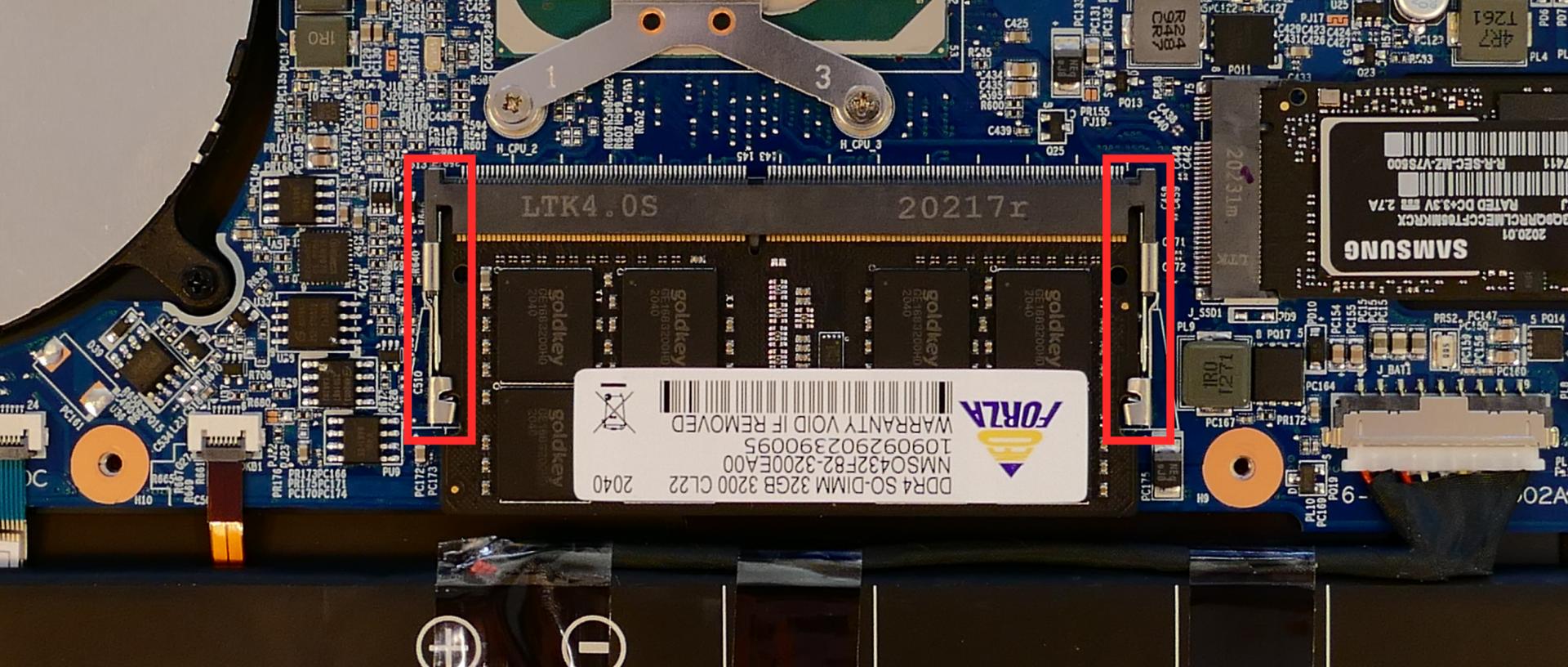
- Remove the RAM from the slot.
- Insert the new RAM (or reseat the existing RAM) by placing it in the keyed slot and pressing down on the RAM until it clicks into place.
Replacing an M.2/NVMe SSD:
This model supports up to two M.2 SSDs. Both M.2 slots are size 2280. SSD-1 supports PCIe NVMe Gen 4, and SSD-2 supports SATA III or PCIe NVMe Generation 3.
Tools required: Cross-head (Phillips) screwdriver
Time estimate: 10 minutes
Difficulty: Easy ●
Steps to replace the M.2 drive:
- Follow the steps above to remove the bottom cover.
- Locate the M.2 drives (or slots.) The SSD-1 slot is above the battery (highlighted yellow here), while the SSD-2 slot is next to the battery (highlighted green).

- Unscrew the retainer screw opposite the M.2 slot.
- Remove the existing M.2 drive by pulling it out of the slot.
- Insert the new M.2 drive into the slot and hold it down.
- Replace the retainer screw.
Replacing the cooling system:
If the CPU fan becomes noisy and cleaning it out doesn't fix the issue, you may need a new CPU fan. Contact Support to start a warranty claim or parts purchase.
Depending on your climate and the age of the machine, it may be necessary to apply new thermal paste between the CPU and the heatsink. Thermal paste helps facilitate effective heat transfer between the CPU and the cooling equipment. These instructions can also be used in the unlikely event your heatsink needs replacing.
Tools required: Cross-head (Phillips) screwdriver
Time estimate: 20 minutes
Difficulty: High ●
Steps to replace the fans/heatsink/thermal paste:
- Follow the steps above to remove the bottom cover.
- Disconnect the small connector plugging the fan into the motherboard, highlighted yellow below.

- Remove the two fan screws (highlighted red above) and any clear tape holding the fan in place.
- Remove the heatsink screws in reverse order, starting with #3, then #2, and finally #1.
- Remove the heatsink/fan from the system, being careful not to bend the heatsink pipe. It may take some pressure to break the seal of the thermal paste.
- Using a paper towel, remove the existing thermal paste. You may also use a small amount of rubbing alcohol to remove excess or difficult-to-remove paste.

- After cleaning the CPU and heatsink, apply a small line of thermal paste directly onto the CPU.

- Carefully replace the fan and heat sink.
- Replace the heatsink screws, starting with #1, then #2, and finally #3.
- Replace the fan screws and plug the fan back in.
- When plugging the fan in, the black wire goes on the left (closest to the side of the machine.)
Replacing the CMOS battery:
The CMOS battery supplies power to the system's CMOS chip. UEFI settings and the computer's hardware clock are stored on the CMOS. If your system doesn't boot, you can reset the CMOS to force a low-level hardware reset. If your clock is constantly resetting, it's likely your CMOS battery needs replacing.
Warning (ingestion hazard): Keep batteries out of reach of children. Death or serious injury can occur if ingested. If a battery is suspected to be swallowed or inserted inside any part of the body, seek immediate medical attention. In the US, you can also call the National Battery Ingestion Hotline for guidance: 1 (800) 498-8666
Tools required: Cross-head (Phillips) screwdriver
Time estimate: 10 minutes
Difficulty: Medium ●
Steps to replace the CMOS battery:
- Follow the steps above to remove the bottom cover.
- Follow the steps above to remove the primary SSD.
- Remove any clear tape that is securing the battery, then pull the battery away from the adhesive holding it to the case.
- If you are only clearing the CMOS and are not replacing the CMOS battery, removing the SSD and CMOS battery is optional, but will make it easier to unplug the CMOS battery connector.

- Unplug the white connector attaching the CMOS battery to the motherboard.
- To clear the CMOS, disconnect the main battery, open the lid of the machine, and hold down the power button for at least 15 seconds to discharge any residual energy in the system.
- Re-connect the CMOS battery and main battery, and replace the M.2 drive and bottom panel.
- Power up the machine. The system may power itself off and on after initial boot; this is normal behavior when the CMOS has been reset.
Replacing the wireless card:
Your system's WiFi and Bluetooth are both handled by the same module. It connects with a standard M.2 2230 slot with PCIe and USB interfaces (E-key).
Tools required: Cross-head (Phillips) screwdriver
Time estimate: 10 minutes
Difficulty: Medium ●
Steps to replace the WiFi/Bluetooth module:
- Follow the steps above to remove the bottom cover.
- Locate the wireless card (next to the CPU fan.) Remove any clear tape that is securing the wires.

- Gently remove the two antennas (highlighted red above) by pulling them up and away from the wireless card.
- Remove the retaining screw opposite the M.2 slot, highlighted yellow above.
- The wireless card will pop up at an angle. Remove the card from the M.2 slot.
- Insert the new wireless card into the M.2 slot at an angle.
- Replace the retaining screw.
- Attach the two antennas by aligning the circular fitting and pressing onto the wireless card. The connectors will snap into place. Use caution when attaching the connectors; the pins can bend, break, or snap.
Replacing the speakers:
The system has two bottom-firing speakers, which can be removed and replaced individually.
Tools required: Cross-head (Phillips) screwdriver
Time estimate: 10 minutes
Difficulty: Medium ●
Steps to replace the speakers:
- Follow the steps above to remove the bottom cover.
- Disconnect the speaker wire from the motherboard.
- This can also be done after freeing the speaker.

- Pull the tops of the purple rubber circles over the black tabs holding them in place.
- Lift the speaker up and off of the plastic posts.

- Slide the new speaker onto the plastic posts and connect it to the motherboard.
Replacing the main battery:
The battery provides primary power whenever the system is unplugged.
The model number for the Lemur Pro 10's battery is L140BAT-4, and the original part number is 6-87-L140S-72B01. Third-party battery sellers may list one or both of these numbers, and may offer other compatible part numbers with the same model number. You can also contact System76 to purchase a replacement battery.
CAUTION: Do not use metal tools to remove the battery. Do not touch the battery contacts with your hands or metal objects. If the battery is damaged during repairs, do not reinsert it into the laptop. Do not continue to use the computer if it contains a damaged battery. It is a potential fire hazard to operate a computer with a damaged battery. Keep children away from, and properly dispose of, the damaged battery. Always dispose of batteries carefully, by placing a piece of tape on the contact points. Take damaged batteries to an electronics recycling center and contact System76 to purchase a replacement. Batteries may explode or leak if exposed to fire, or if improperly handled or discarded. Only use batteries designed for your specific computer. The product that you have purchased contains a rechargeable battery. The battery is recyclable. At the end of its useful life, under various state and local laws, it may be illegal to dispose of this battery into the municipal waste stream. Check with your local solid waste officials for details in your area for recycling options or proper disposal.
Tools required: Cross-head (Phillips) screwdriver
Time estimate: 20 minutes
Difficulty: High ●
Steps to replace the main battery:
- Follow the steps above to remove the bottom cover.
- Unplug the white connector that connects the battery to the motherboard.

- Remove the battery.
- The battery is secured to foam standoffs with double-sided tape.
- A flat plastic object (such as a credit card) can be used to separate the tape from the battery.
- If any tabs from the tape are visible around the perimeter of the battery, hold them down while inserting the plastic tool so they don't get pushed back under the battery.

- Put the battery back (or put your new battery in its place) and plug it back into the motherboard.
Lemur Pro (lemp9)
The System76 Lemur Pro is a laptop with the following specifications:
- CPU
- Supports Intel Comet Lake-U CPUs
- BIOS
- GD25B127D flash chip
- SOIC-8 form factor
- Programmed with System76 Open Firmware
- GD25B127D flash chip
- EC
- ITE IT5570E
- Programmed with System76 EC
- Backlit Keyboard, with standard PS/2 keycodes and SCI hotkeys
- Battery control
- Charger control, using AC adapter or USB-C PD
- Suspend/resume
- Touchpad interface
- Graphics
- GPU: Intel UHD Graphics 620
- GOP driver is recommended, VBT is provided
- eDP display: 14.0" 1920x1080@60Hz LCD
- LCD panel: Innolux N140HCA-EAC (or equivalent)
- External video outputs:
- 1x HDMI 1.4a
- 1x DisplayPort 1.2 over USB-C
- GPU: Intel UHD Graphics 620
- Memory
- Channel 0: 8-GB on-board DDR4 Samsung K4AAG165WA-BCTD
- Channel 1: 8-GB/16-GB/32-GB DDR4 SO-DIMM
- Networking
- M.2 PCIe/CNVi WiFi/Bluetooth options:
- Intel Wi-Fi 6 AX200/AX201
- Intel Wireless-AC 9560
- M.2 PCIe/CNVi WiFi/Bluetooth options:
- Power
- 19V, 3.42A (65W) DC-in port
- Barrel size: 5.5mm (outer), 2.5mm (inner)
- Included AC adapter: AcBel ADA012
- AC power cord type: IEC C7 (non-polarized)
- USB-C charging compatible with 65W+ charger
- 73Wh 4-cell Lithium-Ion battery
- Model number: L140BAT-4
- TI BQ24780S Battery Charger
- 19V, 3.42A (65W) DC-in port
- Sound
- Realtek ALC293D
- Internal speaker
- Internal microphone
- Combined headphone/microphone 3.5-mm jack
- HDMI audio
- USB-C DisplayPort audio
- Storage
- M.2 PCIe/SATA SSD-1
- M.2 PCIe/SATA SSD-2
- RTS5227S MicroSD card reader
- USB
- 1280x720 CCD camera
- USB 3.1 Gen 2 Type-C (left)
- USB 3.1 Gen 2 Type-A (left)
- USB 3.1 Gen 1 Type-A (right)
Lemur Pro (External Overview)
Left side overview:

Right side overview:

Front side overview:

Back side overview:

Keyboard & touchpad overview:

Speakers
The grilles for the built-in speakers are located on the bottom of the machine, angled outward.
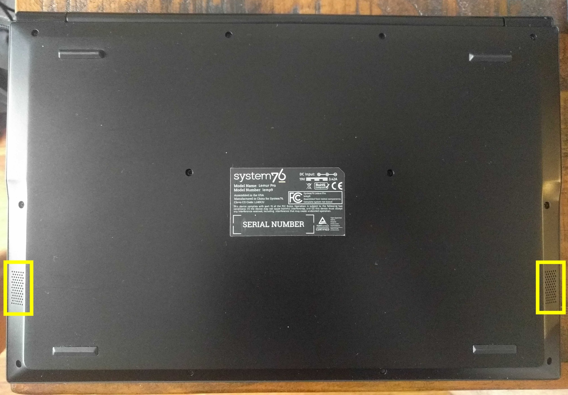
Keyboard Shortcuts
The Lemur Pro has the following actions available using the Fn and Function keys:
| Key | Shortcut | Action |
|---|---|---|
 | Fn+F1 | Toggle trackpad |
 | Fn+F2 | Toggle built-in LCD |
 | Fn+F3 | Mute |
 | Fn+F4 | Keyboard backlight toggle/brightness |
 | Fn+F5 | Volume down |
 | Fn+F6 | Volume up |
 | Fn+F7 | Toggle displays |
 | Fn+F8 | Screen brightness down |
 | Fn+F9 | Screen brightness up |
 | Fn+F10 | Toggle webcam |
 | Fn+F11 | Toggle airplane mode |
 | Fn+F12 | Suspend |
LED indicators
There is an LED light next to the DC-in connector (charger port.) The color and pattern indicate:
- Solid green: Powered on and not suspended.
- Flashing green: Powered on and suspended.
- Solid yellow: Powered off and charging.
- Off: Powered off and not charging.
External Displays
This model supports HDMI and DisplayPort over USB-C connections for external displays.
Lemur Pro (Internal Overview)
User-replaceable components:
The following components can be replaced using the instructions under Parts & Repairs.

- CPU fan/heatsink is highlighted in cyan
- M.2 SSDs are highlighted in yellow
- RAM is highlighted in pink
- Wireless card is highlighted in green
- Battery is highlighted in orange
Other connectors:
These components are not considered user-serviceable, but may be replaced by our hardware team or a local repair shop. The connectors may be reseated for troubleshooting purposes.
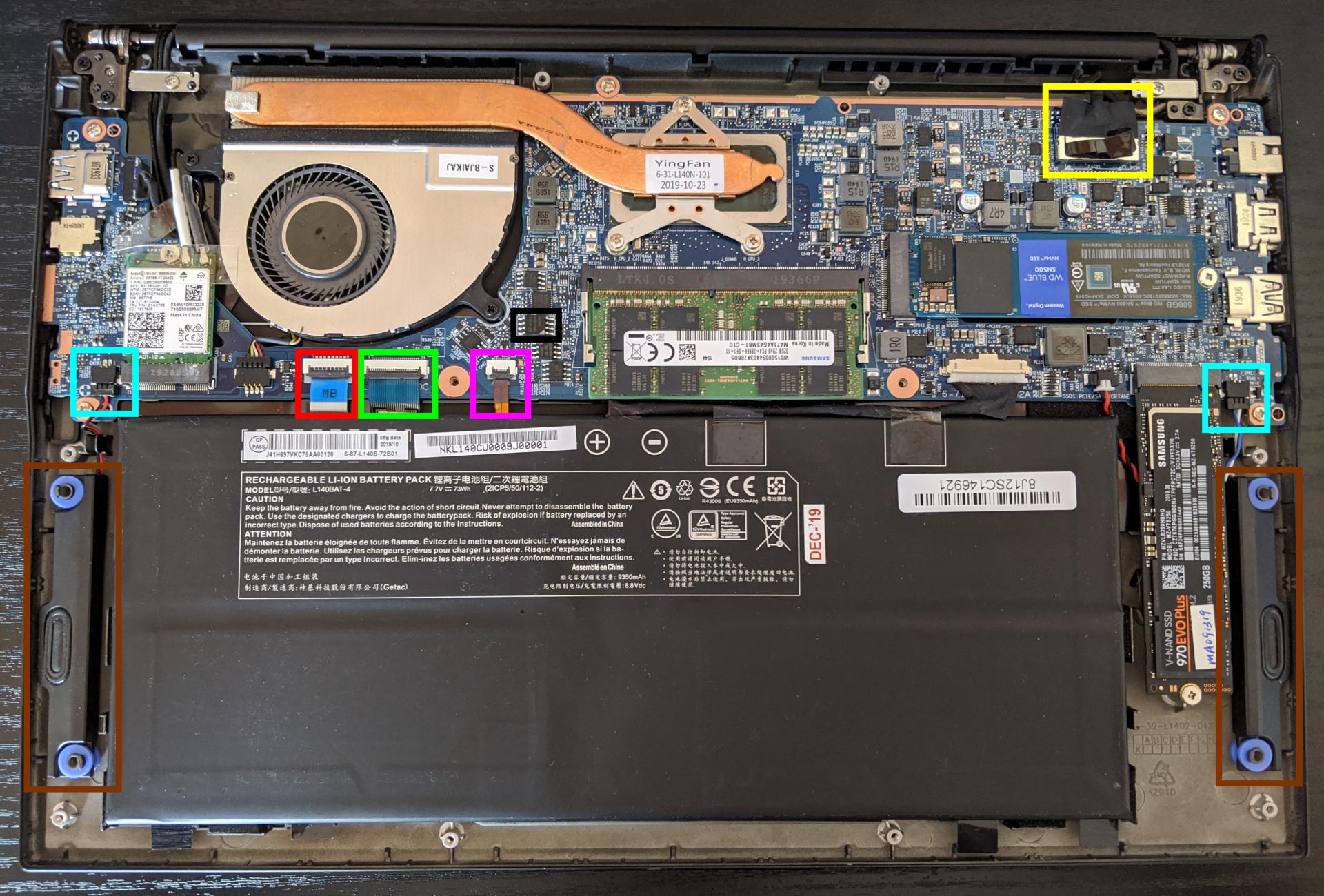
- LCD cable connector is highlighted in yellow
- Touchpad connector is highlighted in red
- Keyboard connector (main) is highlighted in green
- Keyboard backlight connector is highlighted in pink
- Speaker connectors are highlighted in cyan
- Speakers are highlighted in brown
- BIOS flash chip (U29) is highlighted in black
Lemur Pro (Parts & Repairs)
Many components in your Lemur Pro can be upgraded or replaced as necessary. Follow these step-by-step guides for instructions:
- Removing the bottom cover
- Replacing the RAM
- Replacing an M.2/NVMe SSD
- Replacing the fans/heatsink/thermal paste
- Replacing the CMOS battery
- Replacing the WiFi/Bluetooth module
- Replacing the main battery
Removing the bottom cover:
Removing the cover is required to access the internal components. Prior to removing the cover, ensure the AC power is unplugged and all peripherals (including SD cards and USB drives) are unplugged or removed from the system.
Tools required: Cross-head (Phillips) screwdriver
Time estimate: 5 minutes
Difficulty: Easy ●
Screws: 12 total
Steps to remove the bottom cover:
- Place the machine lid-side down.
- Use a soft surface (such as a towel) to avoid scratches.
- Remove the 12 screws from the bottom panel.
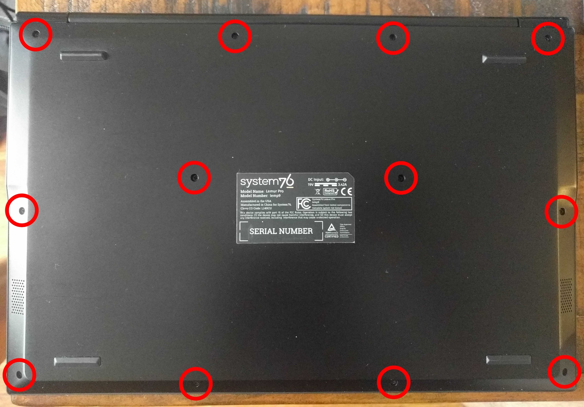
- Lift the bottom cover off, starting from the hinges and working towards the front.
Replacing the RAM:
The Lemur Pro 9 comes with 8GB of RAM soldered onto the motherboard, which cannot be replaced. There is an additional RAM slot, which can support up to a 32GB stick for 40GB of RAM total. If you've purchased new RAM, need to replace your RAM, or are reseating your RAM, follow these steps.
Tools required: Cross-head (Phillips) screwdriver
Time estimate: 10 minutes
Difficulty: Medium ●
Steps to replace the RAM:
- Follow the steps above to remove the bottom cover.
- Press the small tabs on both sides of the RAM simultaneously. The RAM should spring up to an angle.

- Remove the RAM from the slot.
- Insert the new RAM (or reseat the existing RAM) by placing it in the keyed slot and pressing down on the RAM until it clicks into place.
Replacing an M.2/NVMe SSD:
This model supports up to two M.2 SSDs. Both M.2 slots are size 2280, and both slots support SATA III or PCIe NVMe Generation 3.
Tools required: Cross-head (Phillips) screwdriver
Time estimate: 10 minutes
Difficulty: Medium ●
Steps to replace the M.2 drive:
- Follow the steps above to remove the bottom cover.
- Locate the M.2 drives (or slots.) The primary slot is next to the battery (highlighted yellow here), while the secondary slot is above the battery (highlighted red).

- Unscrew the retainer screw opposite the M.2 slot.
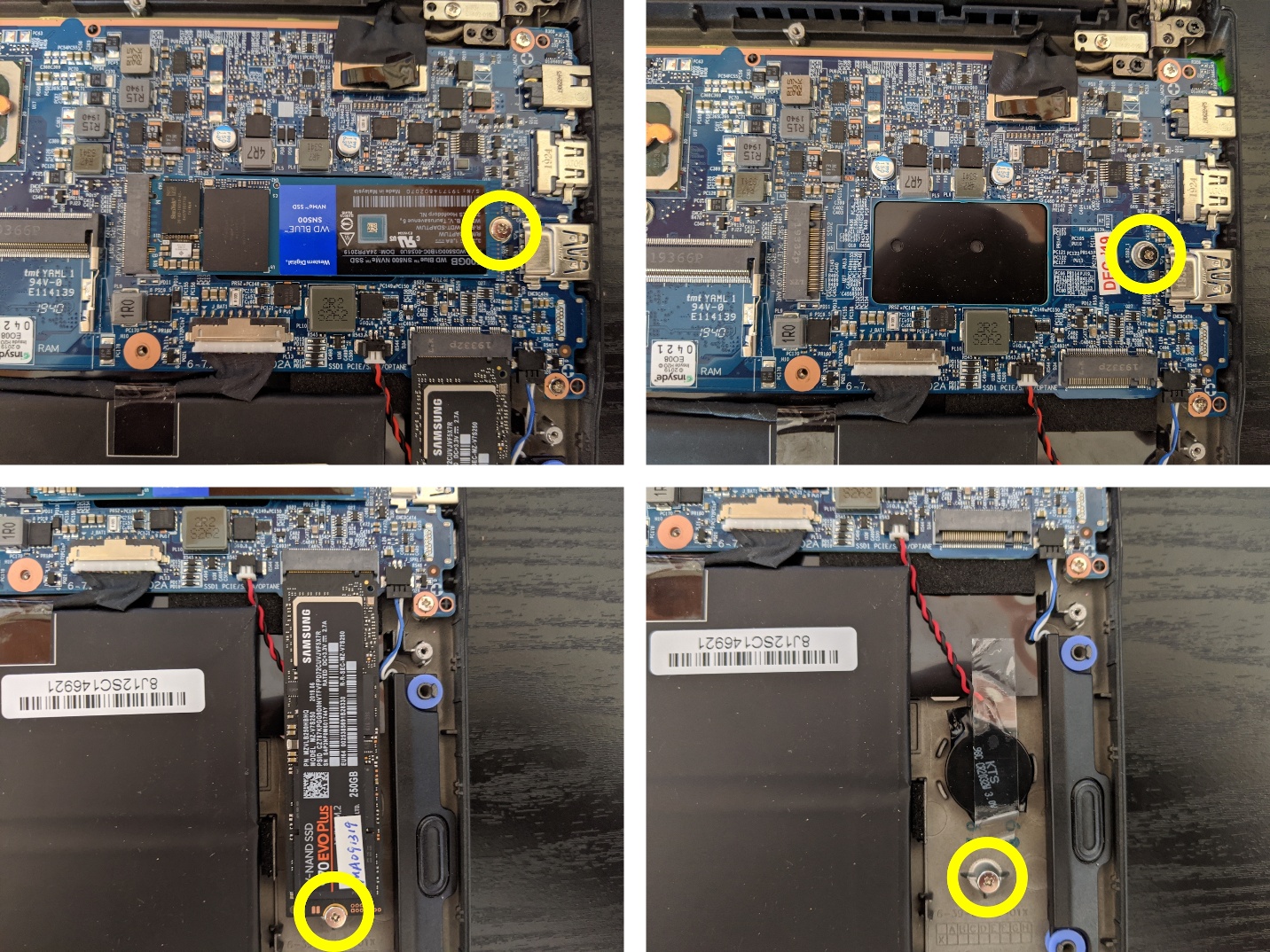
- Remove the existing M.2 drive by pulling it out of the slot.
- Insert the new M.2 drive into the slot and hold it down.
- Replace the retainer screw.
Replacing the cooling system:
If the CPU fan becomes noisy and cleaning it out doesn't fix the issue, you may need a new CPU fan. Contact Support to start a warranty claim or parts purchase.
Depending on your climate and the age of the machine, it may be necessary to apply new thermal paste between the CPU and the heatsink. Thermal paste helps facilitate effective heat transfer between the CPU and the cooling equipment. These instructions can also be used in the unlikely event your heatsink needs replacing.
Tools required: Cross-head (Phillips) screwdriver
Time estimate: 20 minutes
Difficulty: High ●
Steps to replace the fans/heatsink/thermal paste:
- Follow the steps above to remove the bottom cover.
- Locate the CPU heatsink screws (highlighted yellow here) as well as the fan connector and screws (highlighted in red).
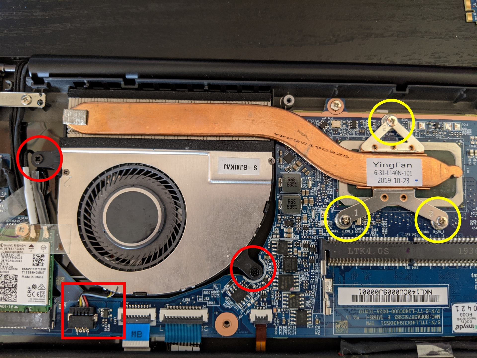
- Disconnect the small connector plugging the fan into the motherboard.
- Remove the heatsink screws in reverse order, starting with #3, then #2, and finally #1.
- Remove the screws holding the fan onto the case.
- Carefully remove the heatsink/fans from the case.
- Using a paper towel, remove the existing thermal paste. You may also use a small amount of rubbing alcohol to remove excess or difficult-to-remove paste.
- After cleaning the CPU and heatsink, apply a small line of thermal paste directly onto the CPU.
- Carefully replace the fan and heat sink.
- Replace the heatsink screws, starting with #1, then #2, and finally #3. Also replace the fan screws. Do not fully tighten until all screws are in place.
- Plug the fan back in.
Replacing the CMOS battery:
The CMOS battery supplies power to the system's CMOS chip. UEFI settings and the computer's hardware clock are stored on the CMOS. If your system doesn't boot, you can reset the CMOS to force a low-level hardware reset. If your clock is constantly resetting, it's likely your CMOS battery needs replacing.
Warning (ingestion hazard): Keep batteries out of reach of children. Death or serious injury can occur if ingested. If a battery is suspected to be swallowed or inserted inside any part of the body, seek immediate medical attention. In the US, you can also call the National Battery Ingestion Hotline for guidance: 1 (800) 498-8666
Tools required: Cross-head (Phillips) screwdriver
Time estimate: 10 minutes
Difficulty: Medium ●
Steps to replace the CMOS battery:
- Follow the steps above to remove the bottom cover.
- Follow the steps above to remove the primary SSD; the CMOS battery is located underneath this SSD.
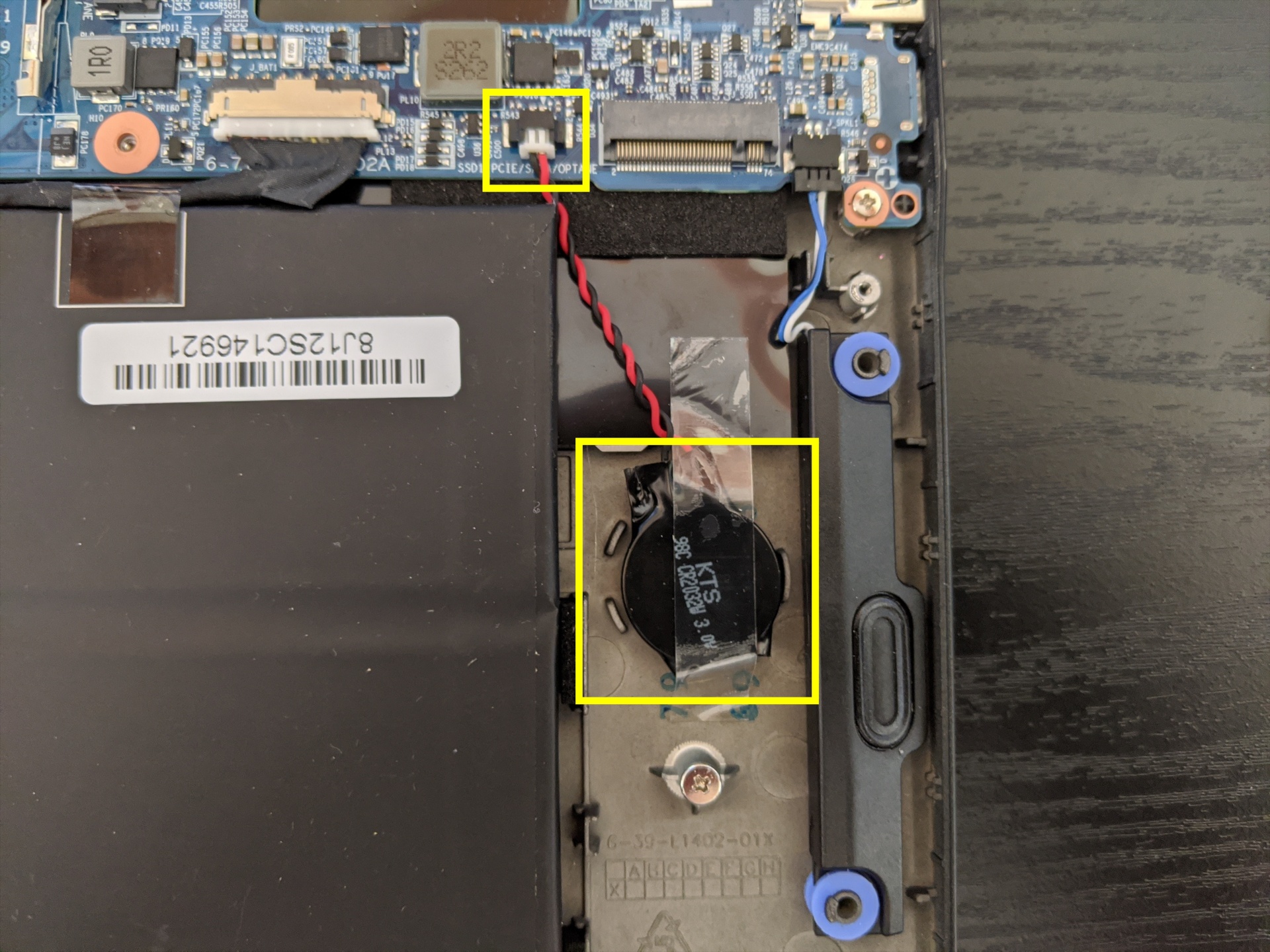
- Unplug the small white connector that connects the CMOS battery to the motherboard. If you are replacing the battery, use a thin plastic tool to pry the battery up from where it's stuck to the case.
- Disconnect the main internal battery, then hold down the power button for at least 15 seconds to discharge any residual energy in the system.
- Re-connect the CMOS battery as well as the main internal battery.
- Power up the Lemur Pro. The system may power itself off and on after initial boot; this is normal behavior when the CMOS has been reset.
Replacing the wireless card:
Your system's WiFi and Bluetooth are both handled by the same module. It connects with a standard M.2 2230 slot with PCIe and USB interfaces (E-key).
Tools required: Cross-head (Phillips) screwdriver
Time estimate: 10 minutes
Difficulty: Medium ●
Steps to replace the WiFi/Bluetooth module:
- Follow the steps above to remove the bottom cover.
- Locate the wireless card (next to the CPU fan.) Remove any tape if present.

- Gently remove the two antennas by pulling them up and away from the wireless card.
- Remove the retaining screw opposite the M.2 slot.
- Remove the wireless card from the M.2 slot.
- Insert the new wireless card into the M.2 slot.
- Replace the retaining screw.
- Attach the two antennas by aligning the circular fitting and pressing onto the wireless card. The connector will snap into place. Use caution when attaching the connectors; the pins can bend, break, or snap.
Replacing the main battery:
The battery provides primary power whenever the system is unplugged.
The model number for the Lemur Pro 9's battery is L140BAT-4, and the original part number is 6-87-L140S-72B01. Third-party battery sellers may list one or both of these numbers, and may offer other compatible part numbers with the same model number. You can also contact System76 to purchase a replacement battery.
CAUTION: Do not use metal tools to remove the battery. Do not touch the battery contacts with your hands or metal objects. If the battery is damaged during repairs, do not reinsert it into the laptop. Do not continue to use the computer if it contains a damaged battery. It is a potential fire hazard to operate a computer with a damaged battery. Keep children away from, and properly dispose of, the damaged battery. Always dispose of batteries carefully, by placing a piece of tape on the contact points. Take damaged batteries to an electronics recycling center and contact System76 to purchase a replacement. Batteries may explode or leak if exposed to fire, or if improperly handled or discarded. Only use batteries designed for your specific computer. The product that you have purchased contains a rechargeable battery. The battery is recyclable. At the end of its useful life, under various state and local laws, it may be illegal to dispose of this battery into the municipal waste stream. Check with your local solid waste officials for details in your area for recycling options or proper disposal.
Tools required: Cross-head (Phillips) screwdriver
Time estimate: 15 minutes
Difficulty: High ●
Steps to replace the main battery:
- Follow the steps above to remove the bottom cover.
- Unplug the white connector that connects the battery to the motherboard.

- Remove the battery.
- The battery is secured to foam standoffs with double-sided tape.
- A flat plastic object (such as a credit card) can be used to separate the tape from the battery.
- If any tabs from the tape are visible around the perimeter of the battery, hold them down while inserting the plastic tool so they don't get pushed back under the battery.
- Put the battery back (or put your new battery in its place) and plug it back into the motherboard.
Meerkat (meer9)
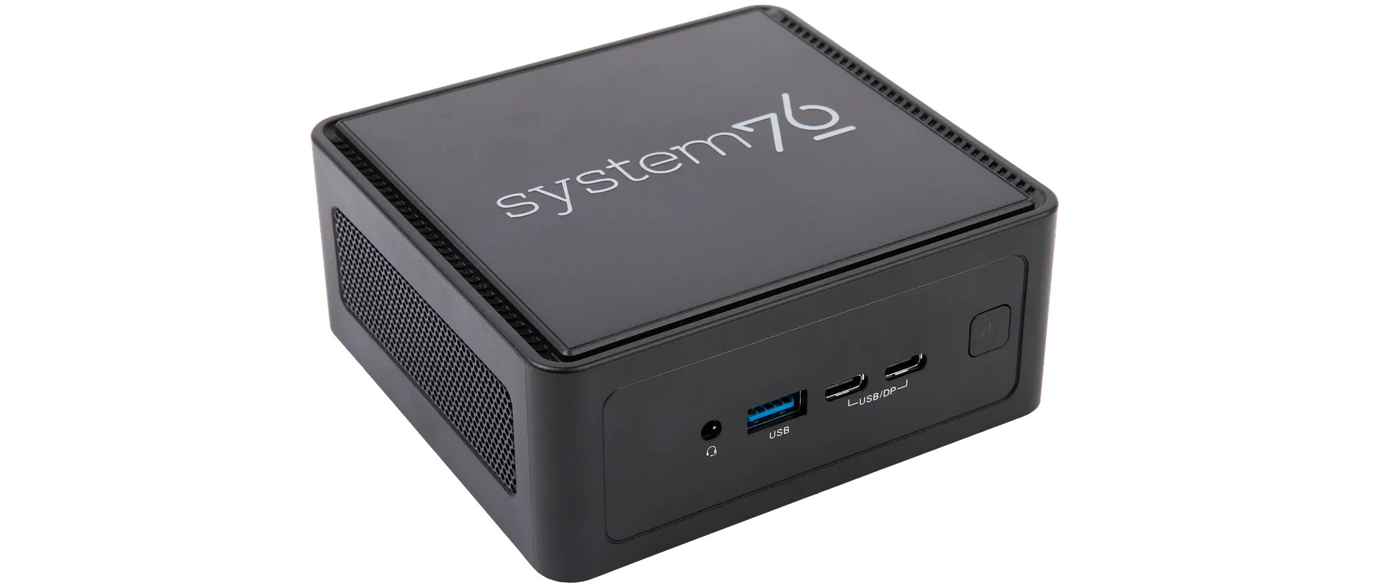
The System76 Meerkat is a desktop with the following specifications:
- CPU
- Supports Intel Core Ultra 1st generation (Meteor Lake) CPUs
- BIOS
- Winbond 25Q256JWEQ flash chip
- Socketed WSON-8 form factor
- Winbond 25Q256JWEQ flash chip
- Graphics
- GPU: Intel Arc graphics
- Video output:
- 2x HDMI 2.1
- 1x DisplayPort 2.1 over USB-C
- 1x DisplayPort 1.4a over USB-C
- Memory
- Up to 96GB (2x48GB) Dual Channel DDR4 SODIMMs @ 5600 MHz
- Networking
- Power
- Core Ultra 7 model:
- 120W (19V, 6.32A) DC-in port
- Barrel size: 5.5mm (outer), 2.5mm (inner)
- Included AC adapter*: AcBel ADC017
- AC power cord type: IEC C5
- 120W (19V, 6.32A) DC-in port
- Core Ultra 5 model:
- 90W (19V, 4.74A) DC-in port
- Barrel size: 5.5mm (outer), 2.5mm (inner)
- Included AC adapter*: AcBel ADA090C19C
- AC power cord type: IEC C5
- 90W (19V, 4.74A) DC-in port
- * Included AC adapter may be a different model with the same specifications.
- Core Ultra 7 model:
- Sound
- 3.5mm headphone/microphone combo jack
- 7.1-channel digital audio output over HDMI and USB-C
- Storage
- 1x M.2 2280/2242 (M key)
- PCIe NVMe Gen 4
- 1x M.2 2242 (M key)
- PCIe NVMe Gen 4
- 1x 2.5"
- SATA III
- 1x M.2 2280/2242 (M key)
- USB
- 1x USB4 Type-C with Thunderbolt 4
- 1x USB 3.2 Gen 2x2 Type-C
- 3x USB 3.2 Gen 2 Type-A
- Dimensions
- 11.75cm x 11.00cm x 4.9cm, 1.0kg
Meerkat (External Overview)
Front side overview:

Left side overview:

Right side overview:

Back side overview:

Meerkat (Internal Overview)
Component overview:

- M.2 2280 (PCIe NVMe Gen 4) SSD slot is highlighted in yellow
- M.2 2242 (PCIe NVMe Gen 4) SSD slot is highlighted in cyan
- 2.5" SATA ribbon connector is highlighted in green
- Wireless card (underneath the NVMe 2280 SSD) is highlighted in red
- RAM slots are highlighted in pink
- Motherboard screws are highlighted in white
- BIOS chip (underneath the M.2 SSDs) is highlighted in black
Meerkat (Parts & Repairs)
Several components in your Meerkat can be upgraded or replaced as necessary. Power the machine off and unplug all peripherals before working with any internal components. Then, follow these step-by-step guides for instructions:
- Removing the bottom panel
- Replacing an M.2 drive
- Replacing the RAM
- Replacing the 2.5" storage drive
- Replacing the WiFi/Bluetooth module
- Removing the motherboard
- Replacing the fan
- Replacing the CMOS battery
- Replacing the thermal paste
- Mounting with VESA mount
Removing the bottom panel:
The bottom panel can be removed to access the internal components.
Tools required: Cross-head (Phillips) screwdriver
Time estimate: 1 minute
Difficulty: Easy ●
Steps to remove the bottom panel:
- Place the machine lid-side down.
- Use a soft surface (such as a towel) to avoid scratches.
- Remove the four screws in the corners.
- The screws are not attached to the surrounding rubber rings.
- If any of the rubber rings come off of the bottom panel, put them back before replacing the screws.

- Lift the bottom panel off of the machine.
- If a 2.5" storage drive is installed, the cable will keep the bottom panel attached to the motherboard; flip the bottom panel over in the direction of the cable.
Replacing an M.2 drive:
Your Meerkat has two M.2 slots, which support PCIe NVMe Gen 4. Slot 1 fits sizes 2280 and 2242, while Slot 2 fits size 2242 only. (Adapter brackets can be used to install size 2230 SSDs into the 2242 slots.)
Tools required: Cross-head (Phillips) screwdriver
Time estimate: 6 minutes
Difficulty: Easy ●
Steps to replace the M.2 drives:
- Follow the steps above to remove the bottom panel.
- Unscrew the retainer screw opposite the M.2 slot.
- The Slot 1 (2280/2242) screw is highlighted cyan below, while the Slot 2 (2242) screw is highlighted yellow.
- If you're installing a drive into a slot for the first time and the screw is not present in the system, it was included separately in your Meerkat's box.

- Remove the existing M.2 drive by pulling it out of the slot.
- Insert the new M.2 drive into the slot and hold it in place.
- Replace the retainer screw.
- If you are installing a 2242 drive in the 2280/2242 slot where a 2280 drive was previously installed, you may need to remove the wireless card's screw (highlighted red below) and replace it with the adapter nut from your Meerkat's box, then insert the 2242 drive and secure its screw into the adapter nut.
- If the base nut comes out of the motherboard when removing the wireless card screw, screw it back into the motherboard (below the wireless card) before adding the adapter nut on top.
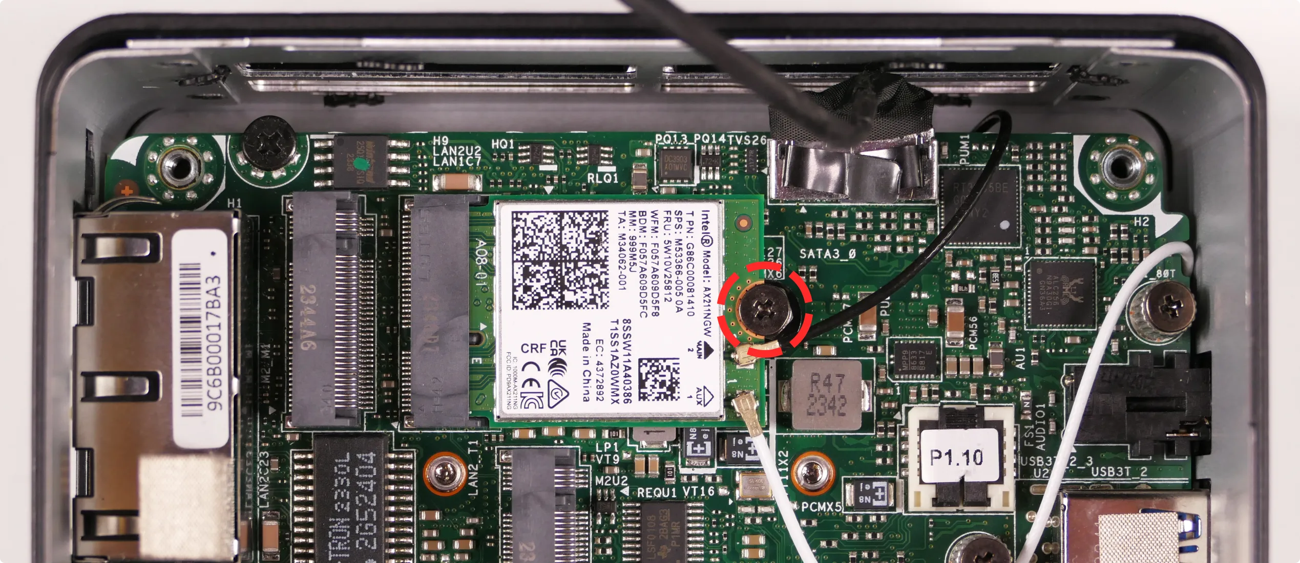
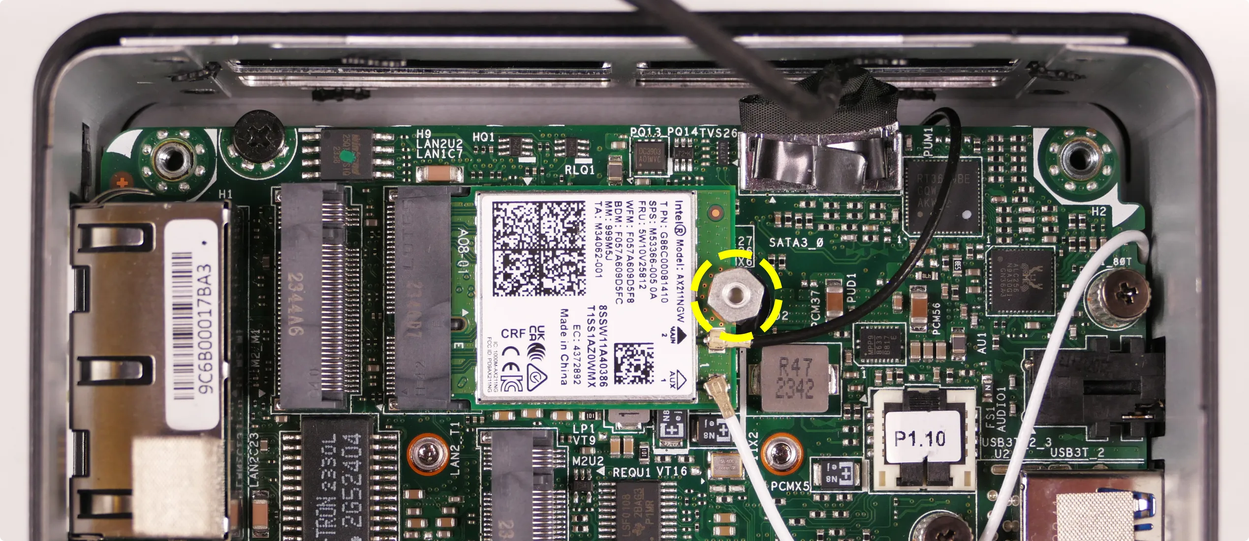
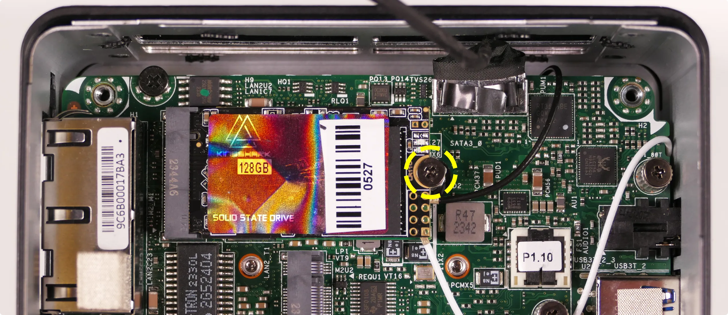
- If the base nut comes out of the motherboard when removing the wireless card screw, screw it back into the motherboard (below the wireless card) before adding the adapter nut on top.
- If you are installing a 2242 drive in the 2280/2242 slot where a 2280 drive was previously installed, you may need to remove the wireless card's screw (highlighted red below) and replace it with the adapter nut from your Meerkat's box, then insert the 2242 drive and secure its screw into the adapter nut.
- Replace the bottom panel.
- If you're using an SSD slot for the first time, remove the blue tape covering the corresponding thermal pad on the inner side of the bottom panel before reinstalling the panel.
Replacing the RAM:
The Meerkat 9 supports up to 96GB (2x48GB) of DDR5 SO-DIMMs running at 5600MHz. If you've purchased new RAM, need to replace your RAM, or are reseating your RAM, follow these steps.
Tools required: Cross-head (Phillips) screwdriver
Time estimate: 5 minutes
Difficulty: Easy ●
Steps to replace the RAM:
- Follow the steps above to remove the bottom panel.
- Pull the small tabs on both sides of the RAM away from the RAM stick simultaneously. The RAM should spring up to an angle.

- Remove the RAM from the slot.
- Insert the new RAM (or reseat the existing RAM) by placing it in the keyed slot and pressing down until it clicks into place.
Replacing the 2.5" storage drive:
The Meerkat 9 supports one 2.5" SATA III drive, which mounts onto the bottom panel.
Tools required: Cross-head (Phillips) screwdriver
Time estimate: 7 minutes
Difficulty: Easy ●
Steps to replace the 2.5" storage drive:
- Follow the steps above to remove the bottom panel.
- Unplug the SATA cable from the existing 2.5" drive (if installed).
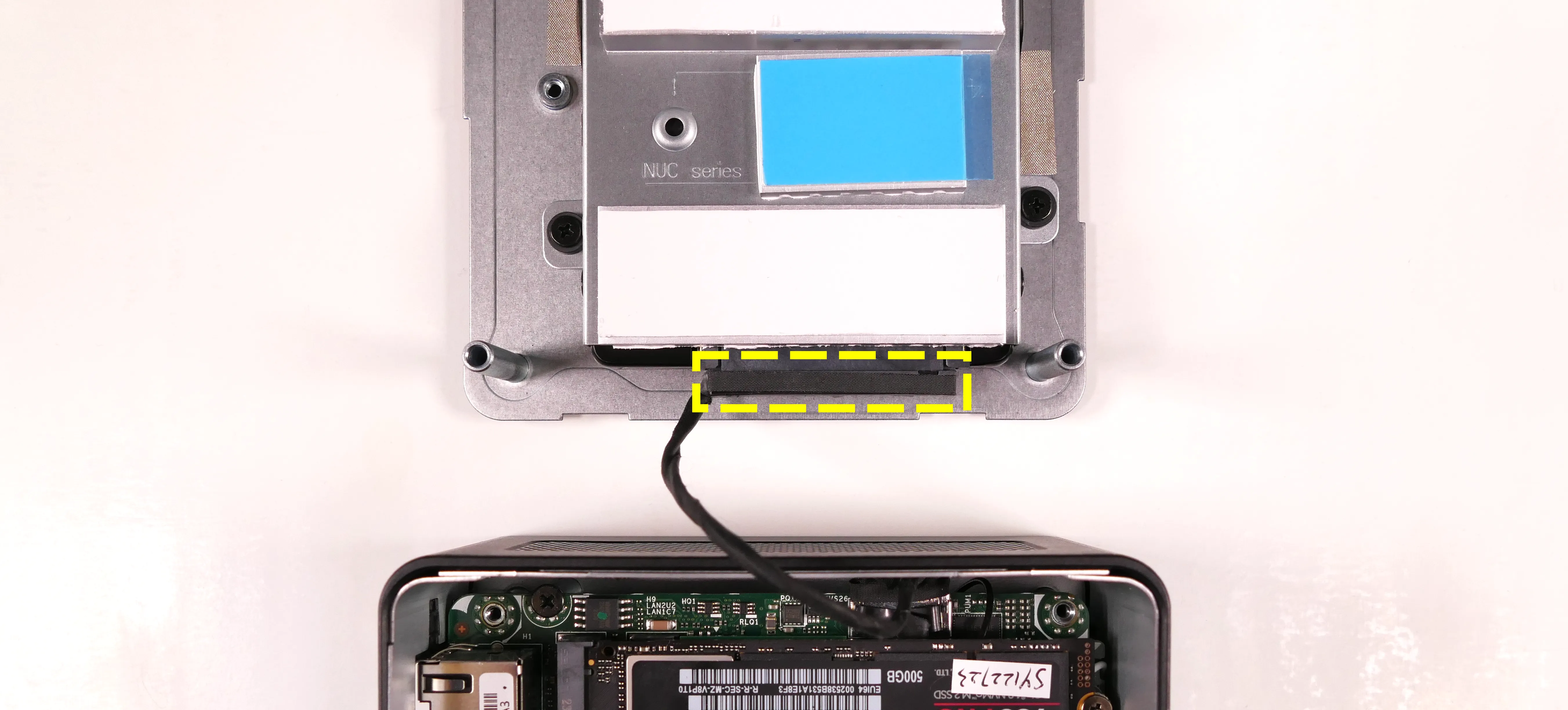
- Unscrew the existing 2.5" drive from the sides of the drive caddy (if installed).
- It is not necessary to remove the drive caddy from the bottom panel.

- Slide the old drive out of the drive caddy (if installed), then slide the new drive in.
- Screw in the four side drive screws (two per side).
- If your Meerkat did not come with a 2.5" drive installed, then the screws were included separately in the box.
- Plug the SATA cable into the new 2.5" drive.
- Replace the bottom panel.
Resetting the CMOS:
A CMOS reset will restore the UEFI firmware settings to their factory defaults, which can sometimes help if the system is not booting.
Tools required: Cross-head (Phillips) screwdriver and (optionally) tweezers
Time estimate: 13 minutes
Difficulty: Medium ●
Steps to reset CMOS:
- Follow the steps above to remove the bottom panel and remove the M.2 drive.
- Disconnect the CMOS battery connector (labeled
RTCBATon the motherboard).- Try to pull the plug, not the wires.

- Hold down the power button for at least 15 seconds to discharge any residual energy in the system.
- Reconnect the CMOS battery.
- Replace the M.2 drive and bottom panel.
- Power up the machine. The system may take longer than usual to boot; this is normal behavior when the CMOS has been reset.
Replacing the wireless card:
Your Meerkat's WiFi and Bluetooth are both handled by the same module. It is a standard M.2 2230 slot with PCIe and USB interfaces (E-key).
Tools required: Cross-head (Phillips) screwdriver, 5.0 mm hex socket
Time estimate: 15 minutes
Difficulty: Medium ●
Steps to replace the WiFi/Bluetooth module:
- Follow the steps above to remove the bottom panel and remove the M.2 drive from Slot 1.
- Gently remove the two antennas (highlighted cyan below) by pulling them up and away from the wireless card.

- Remove the wireless card screw (or M.2 adapter nut) holding the wireless card down.
- If the base nut (below the wireless card) comes out of the motherboard during this step, screw it back into the motherboard before replacing the wireless card.
- The wireless card will pop up at an angle. Remove the card from the M.2 slot.
- Insert the new wireless card into the M.2 slot at an angle.
- Replace the retaining standoff.
- Attach the two antennas by aligning the circular fittings and pressing onto the wireless card. The connectors will snap into place.
- Use caution when attaching the connectors; the pins can bend, break, or snap.
Removing the motherboard:
Removing the motherboard is necessary for replacing the CMOS battery, cooling fan, and thermal paste.
Tools required: Cross-head (Phillips) screwdriver
Time estimate: 20 minutes
Difficulty: High ●
Steps to remove the motherboard:
- Follow the steps above to remove the bottom panel.
- Remove the M.2 drive and optionally unplug the SATA cable from the motherboard, highlighted cyan below.
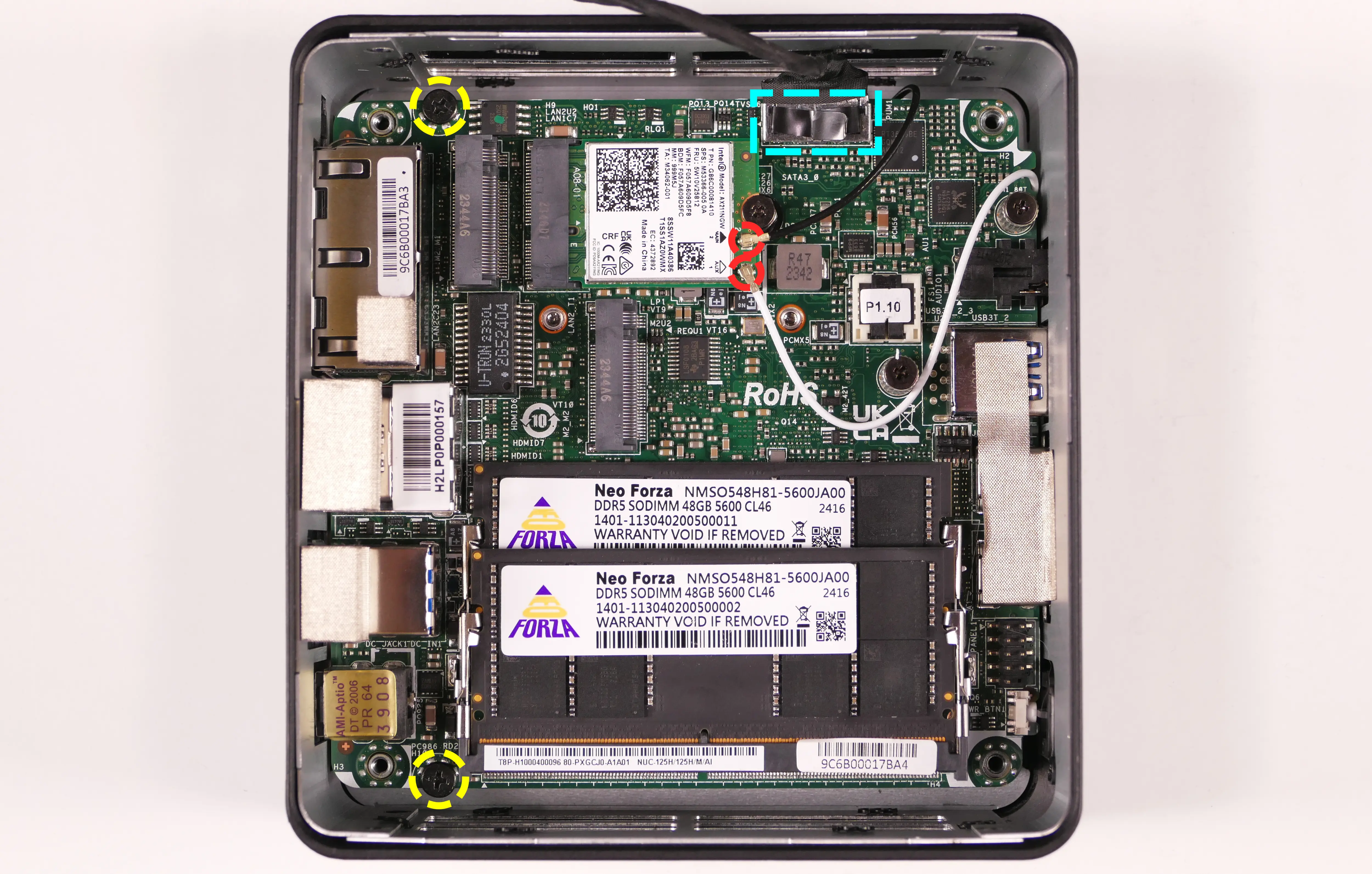
- Disconnect the two wireless antenna cables, highlighted red above.
- Remove the two motherboard mounting screws near the back ports of the machine, highlighted yellow above.
- Carefully pull the motherboard out of the case.
- It is easiest to lift from the back ports, pivoting the board against the front side of the chassis.
- Slightly squeezing the sides of the chassis near the back ports can help provide more clearance while pivoting the motherboard.
- Slowly peel the tape above the front USB-C ports away from the chassis with the motherboard.
- When reinstalling the motherboard, ensure both the front and back ports are aligned with their chassis cutouts.
Replacing the fan:
The cooling fan can be removed to clean dust out of the cooling system or to access the CPU heatsink when replacing the thermal paste. The CMOS battery is mounted on the underside of the fan.
Part numbers:
- The fan is a Delta Electronics
BSC0805HA-00.
Tools required: Cross-head (Phillips) screwdriver
Time estimate: 25 minutes
Difficulty: High ●
Steps to replace the fan:
- Follow the steps above to remove the bottom panel, unplug the wireless card antennas, and remove the motherboard.
- In the below photos, the SATA cable has also been unplugged as detailed in removing the motherboard.
- Unplug the fan connector, highlighted red below.

- Unplug the CMOS battery connector, highlighted yellow above.
- This step is optional if you are not replacing the fan or the CMOS battery.
- Loosen the three fan screws (highlighted cyan above) and remove the fan.
- The two small, light silver screws (along the bottom edge) are held captive, and will not fully come away from the fan.
- The larger, dark silver screw will come apart from the fan when fully loosened.
- Peel the CMOS battery off of the old fan and stick it onto the new fan (if applicable).
- Reinstall the fan and fan screws, then plug the CMOS and fan connectors back into the motherboard.
- Reinstall the motherboard, reconnect the wireless card antennas, reconnect the SATA cable and reinstall the M.2 drive (as necessary), and reinstall the bottom panel.
Replacing the CMOS battery:
The CMOS battery supplies power to the system's CMOS chip, where UEFI settings and the computer's hardware clock are stored. If your clock is constantly resetting, your CMOS battery may need to be replaced.
Warning (ingestion hazard): Keep batteries out of reach of children. Death or serious injury can occur if ingested. If a battery is suspected to be swallowed or inserted inside any part of the body, seek immediate medical attention. In the US, you can also call the National Battery Ingestion Hotline for guidance: 1 (800) 498-8666
Part numbers:
- The CMOS battery is a standard 3V CR2032 battery.
- The stock battery is Toshiba brand.
Tools required: Cross-head (Phillips) screwdriver
Time estimate: 27 minutes
Difficulty: High ●
Steps to replace the CMOS battery:
-
Follow the steps above to remove the bottom panel, remove the motherboard, and remove the fan.
-
If not done while removing the fan, unplug the CMOS battery connector, highlighted yellow below.

- Slowly pull the CMOS battery away from where it's adhered to the fan. The double-sided tape may remain on the fan after the CMOS battery is removed.
- Stick the new CMOS battery onto the fan (next to the black plastic screw arm), then plug the new CMOS battery in and replace the fan, motherboard, and bottom panel.
Replacing the thermal paste:
Thermal paste helps facilitate heat transfer between the CPU and the cooling equipment. Depending on your climate and the age of the machine, replacing the thermal paste between the CPU and the heatsink may help the system run cooler.
Tools required: Cross-head (Phillips) screwdriver
Time estimate: 30 minutes
Difficulty: High ●
Steps to replace the thermal paste:
- Follow the steps above to remove the bottom panel, remove the M.2 drive, unplug the wireless card, remove the motherboard, and remove the fan and attached CMOS battery.
- Loosen the four heatsink screws in diagonal pairs (starting with one screw, then the one diagonal to it, followed by the other pair).
- The screws are held captive and will not completely separate from the heatsink.

- Gently lift the heatsink off of the motherboard.
- Using a paper towel, clean the old thermal paste off of the heatsink and CPU. You may also use a small amount of rubbing alcohol if the old paste is dried or difficult to remove.


- Apply a small line of thermal paste directly onto the CPU chip.

- Replace the heatsink and tighten the four screws.
- Partially tighten each screw first, then fully tighten them in diagonal pairs.
- Reinstall the fan and CMOS battery, motherboard, wireless card antennas, M.2 drive, and bottom panel.
Mounting with VESA Mount:
Your Meerkat comes with a VESA mount adapter, which allows it to be mounted on the back of a display. This allows operation as an all-in-one, taking up no additional desk space.
Because the Meerkat mounts to the display's VESA mount, this will only work on displays which aren't already mounted via the VESA mount.
Tools required: Cross-head (Phillips) screwdriver
Time estimate: 10 minutes
Difficulty: Easy ●
Steps to mount with the VESA adapter:
- Insert the two shoulder screws into the bottom of the Meerkat.

- Use the remaining four screws to attach the VESA mounting plate, using the arrow to guide the orientation.

- Insert the two shoulder screws in the Meerkat into the two holes in the mounting plate (highlighted cyan above), then set the Meerkat down so it hangs on the mounting plate.
- The Meerkat can be mounted in either direction.

Meerkat (meer8)
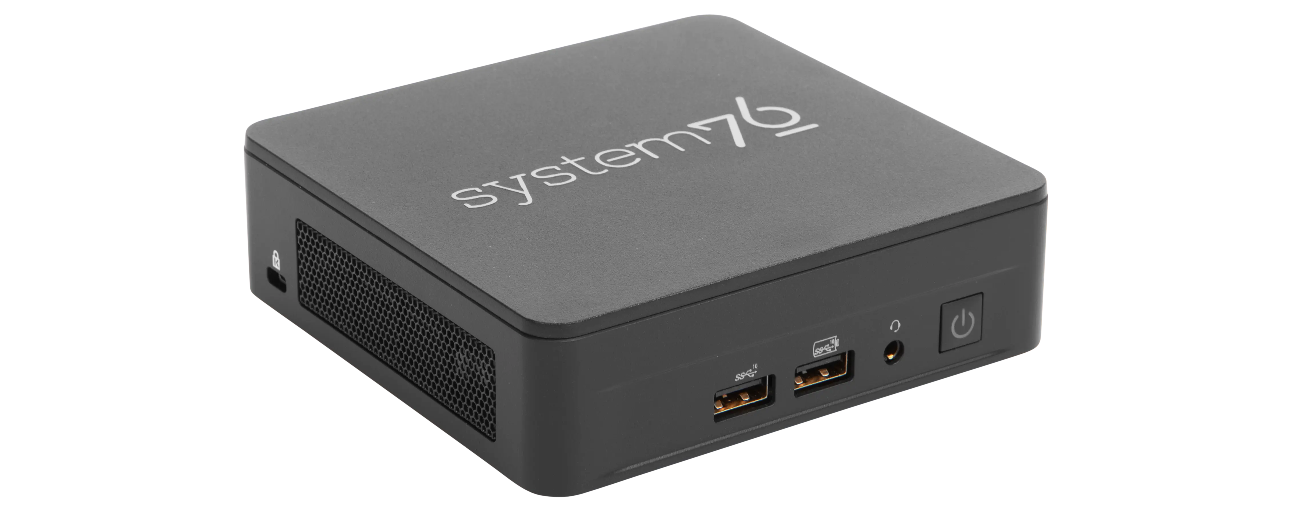
The System76 Meerkat is a desktop with the following specifications:
- CPU options
- Graphics
- GPU:
- i3 model: Intel UHD Graphics
- i5 & i7 model: Intel Iris Xe Graphics
- Video output:
- 2x HDMI 2.1
- 2x DisplayPort 1.4a over USB-C
- GPU:
- Memory
- Up to 64GB (2x32GB) Dual Channel DDR4 SODIMMs @ 3200 MHz
- Networking
- Power
- i3 model:
- 90W (19V, 4.74A) DC-in port
- Barrel size: 5.5mm (outer), 2.5mm (inner)
- Included AC adapter*: APD DA-90J19
- AC power cord type: IEC C5
- 90W (19V, 4.74A) DC-in port
- i5 and i7 models:
- 120W (20V, 6.0A) DC-in port
- Barrel size: 5.5mm (outer), 2.5mm (inner)
- Included AC adapter*: Delta ADP-120VH
- AC power cord type: IEC C5
- 120W (20V, 6.0A) DC-in port
- * Included AC adapter may be a different model with the same specifications.
- i3 model:
- Sound
- 3.5mm headphone/microphone combo jack
- 7.1-channel digital audio output over HDMI and USB-C
- Storage
- 1x M.2 2280 (M key)
- PCIe NVMe Gen 4
- 1x M.2 2242 (B key)
- SATA III
- In the tall model, the optional I/O add-on occupies this slot.
- Tall model only: 1x 2.5"
- SATA III
- 1x M.2 2280 (M key)
- USB
- 2x USB4 Type-C with Thunderbolt 4
- 3x USB 3.2 Gen 2 Type-A
- 1x USB 2.0 Type-A
- Optional I/O add-on (tall model only): additional 2x USB 2.0 Type-A
- Dimensions
- Short: 117 x 112 x 37mm
- Tall: 117 x 112 x 54mm
Meerkat (External Overview)
Front side overview:
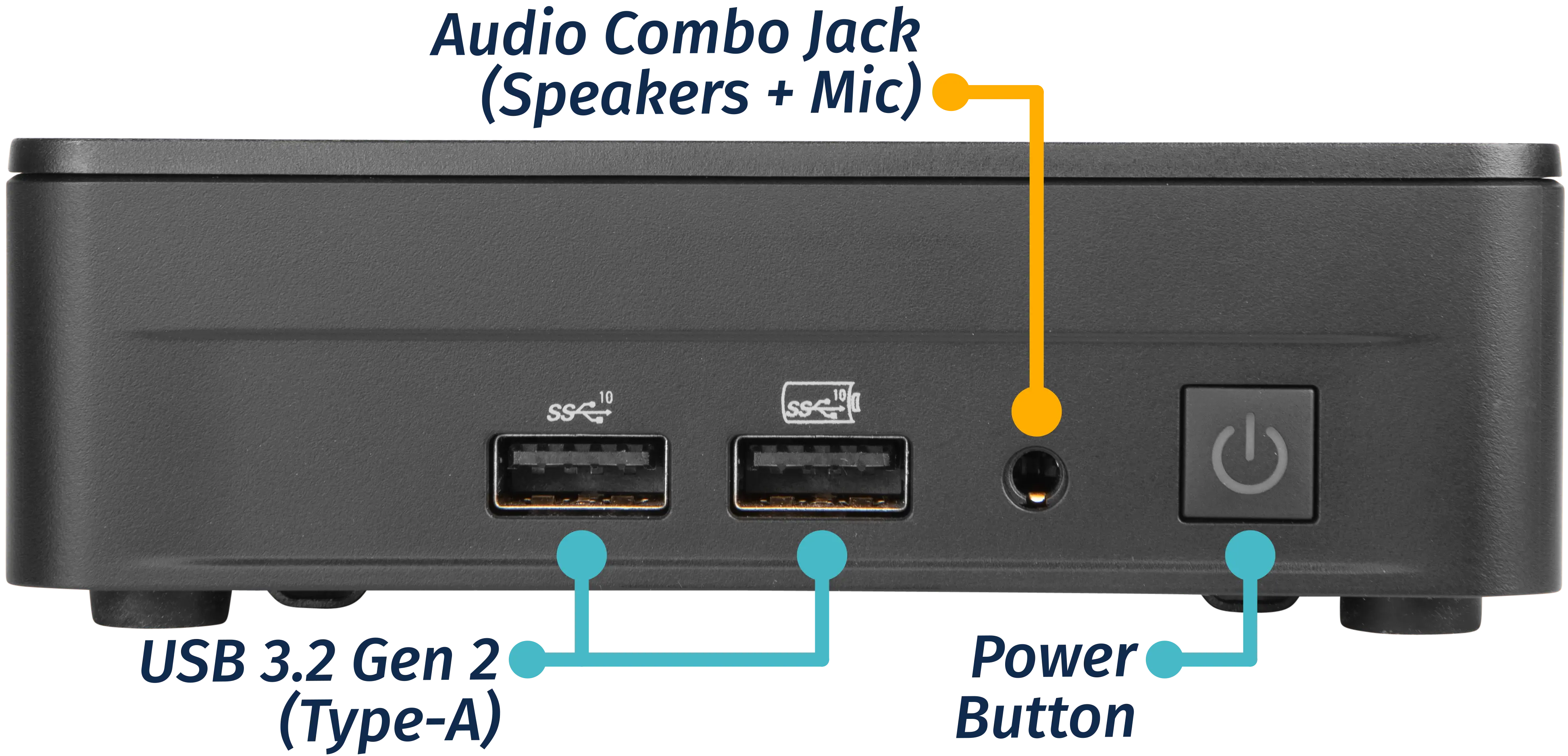
Left side overview:
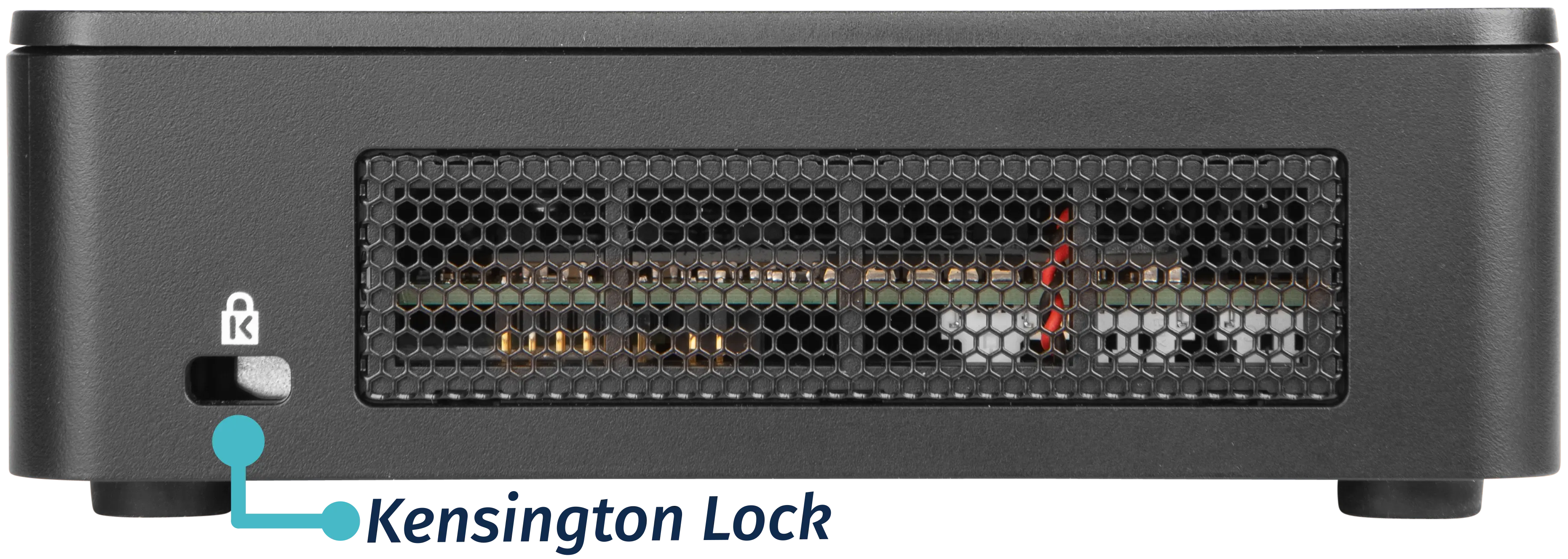
Right side overview:
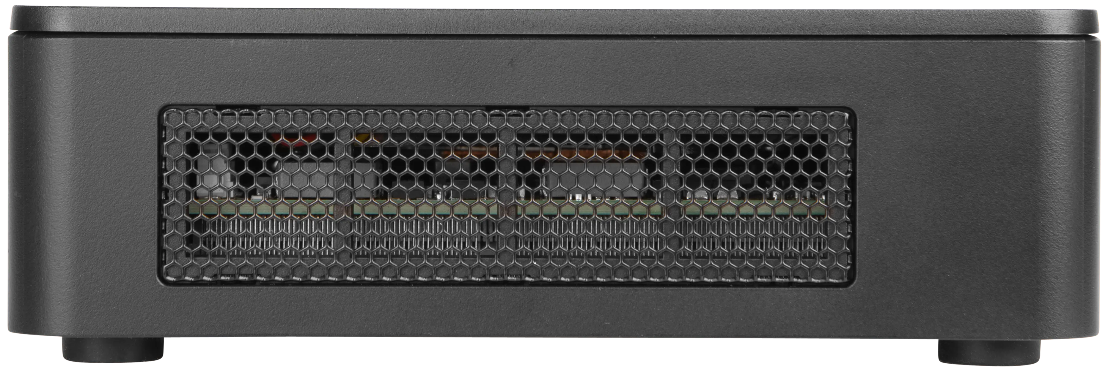
Back side overview:
Short model:
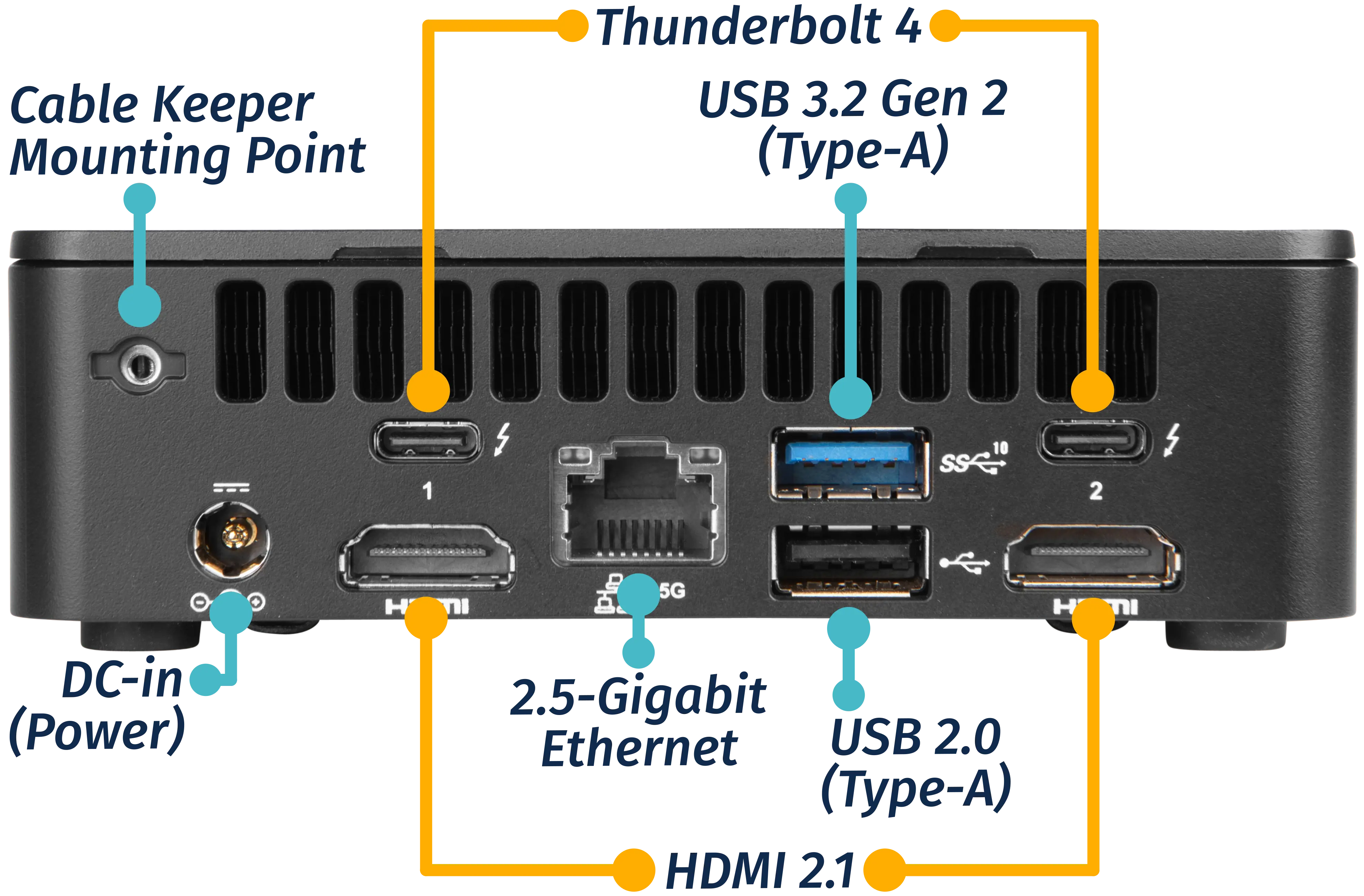
Tall model with optional I/O add-on:
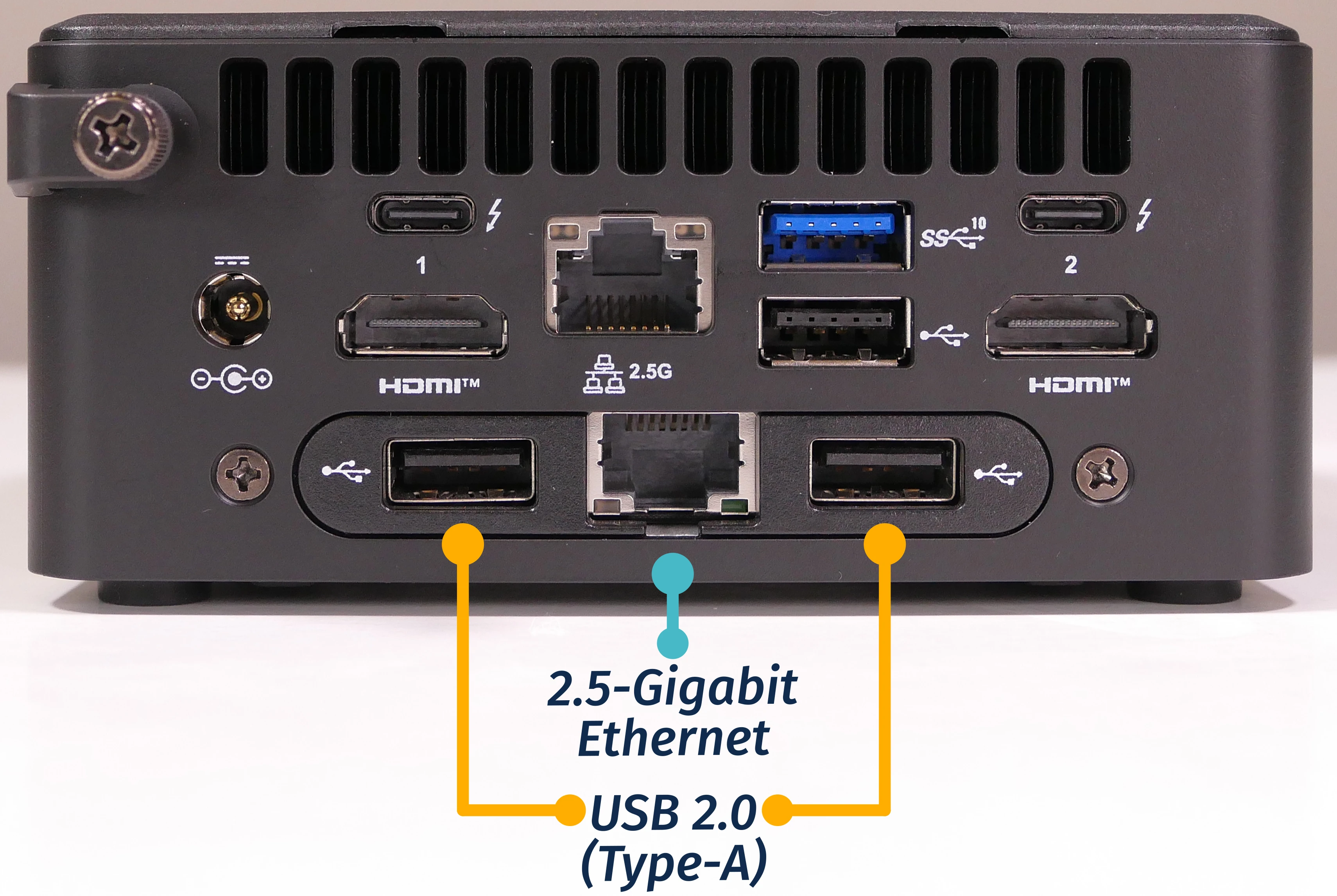
Meerkat (Internal Overview)
Component overview:

- M.2 2280 (NVMe) SSD slot is highlighted in yellow
- M.2 2242 (SATA) SSD slot is highlighted in cyan
- Occupied by the optional I/O add-on (if installed) in the tall model
- 2.5" SATA ribbon connector is highlighted in green
- Only used in the tall model
- Wireless card (underneath the NVMe SSD) is highlighted in red
- RAM slots are highlighted in pink
- CMOS battery connector is highlighted in white
- Motherboard screws are highlighted in black
Meerkat (Parts & Repairs)
Several components in your Meerkat can be upgraded or replaced as necessary. Power the machine off and unplug all peripherals before working with any internal components. Then, follow these step-by-step guides for instructions:
- Removing the bottom panel
- Replacing an M.2 drive
- Replacing the RAM
- Adding/removing a 2.5" storage drive
- Resetting the CMOS
- Replacing the WiFi/Bluetooth module
- Removing the optional I/O add-on
- Removing the motherboard
- Replacing the fan
- Replacing the CMOS battery
- Replacing the thermal paste
- Removing the cable keeper
- Mounting with VESA mount
Removing the bottom panel:
The bottom panel can be removed to access the internal components.
Tools required: Cross-head (Phillips) screwdriver
Time estimate: 1 minute
Difficulty: Easy ●
Steps to remove the bottom panel:
- Place the machine lid-side down.
- Use a soft surface (such as a towel) to avoid scratches.
- Completely loosen the four screws in the corners.
- The screws are attached and will not completely separate from the bottom panel.
- Multiple sets of screws may be present on the tall model; the outermost screws (surrounded by rubber feet) are for the bottom panel.

- Gently lift the bottom panel out of the machine.
- If your Meerkat is the tall model (with a 2.5" drive slot), be careful not to damage the thin cable running from the motherboard to the bottom panel.
Replacing an M.2 drive:
Your Meerkat has two M.2 slots. The first slot is size 2280 and supports PCIe NVMe Gen 4. The second slot is size 2242 and supports SATA III.
If you have the tall model Meerkat with the optional I/O expansion module, it will occupy the 2242 slot.
Tools required: Cross-head (Phillips) screwdriver
Time estimate: 6 minutes
Difficulty: Easy ●
Steps to replace the M.2 drive:
- Follow the steps above to remove the bottom panel.
- Unscrew the retainer screw opposite the M.2 slot.
- The 2280 slot screw is highlighted cyan below, while the 2242 slot screw is highlighted red.
- In the tall model, if the optional I/O expansion module is installed, its connector will occupy the 2242 slot (highlighted red).

- Remove the existing M.2 drive by pulling it out of the slot.
- Insert the new M.2 drive into the slot and hold it in place.
- Replace the retainer screw.
- Replace the bottom panel.
Replacing the RAM:
The Meerkat 8 supports up to 64GB (2x32GB) of DDR4 SO-DIMMs running at 3200MHz. If you've purchased new RAM, need to replace your RAM, or are reseating your RAM, follow these steps.
Tools required: Cross-head (Phillips) screwdriver
Time estimate: 5 minutes
Difficulty: Easy ●
Steps to replace the RAM:
- Follow the steps above to remove the bottom panel.
- Pull the small tabs on both sides of the RAM away from the RAM stick simultaneously. The RAM should spring up to an angle.

- Remove the RAM from the slot.
- Insert the new RAM (or reseat the existing RAM) by placing it in the keyed slot and pressing down until it clicks into place.
Adding/removing a 2.5" storage drive:
If your Meerkat is the tall variety, it has a 2.5" SATA III drive bay built into the bottom panel.
Tools required: Cross-head (Phillips) screwdriver
Time estimate: 7 minutes
Difficulty: Easy ●
Steps to add/remove a 2.5" storage drive:
- If a 2.5" drive was not already installed, pull the four rubber plugs out of the bottom of the Meerkat.
- This can be done before or after opening the machine.
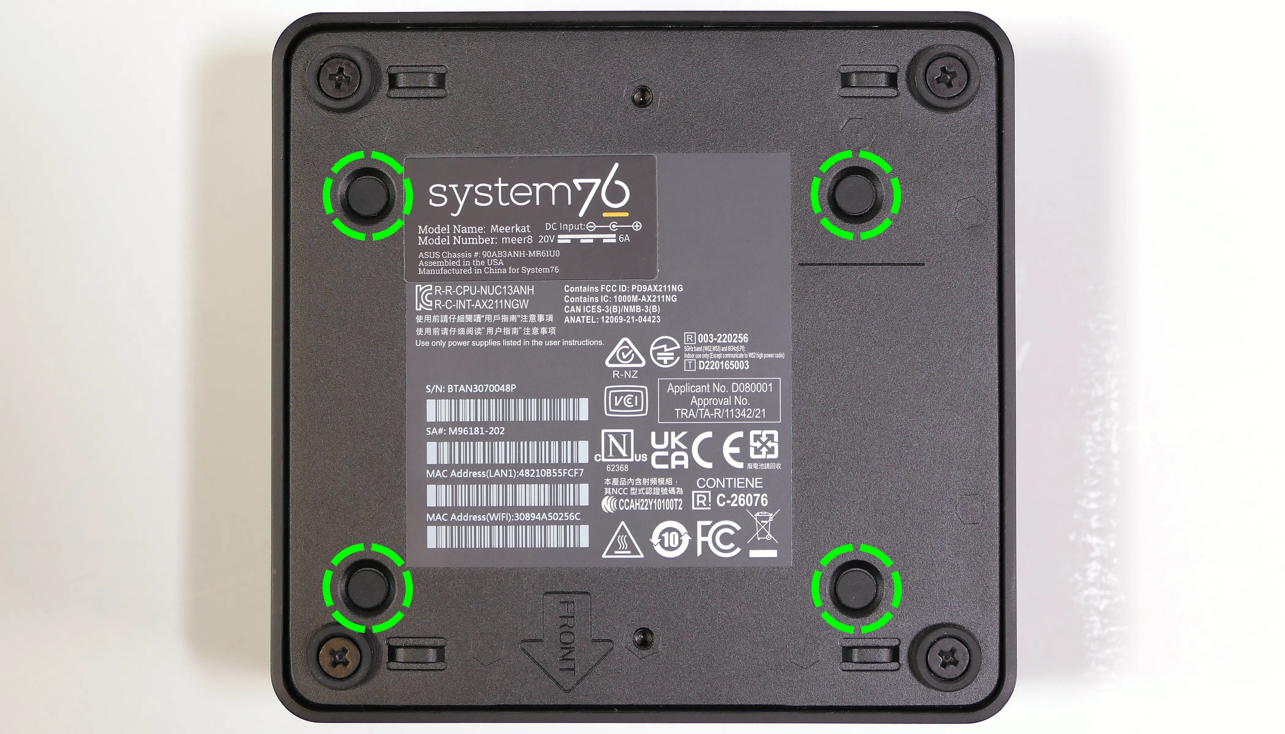
- Follow the steps above to remove the bottom panel.
- Locate the SATA connector in the bottom panel and orient your drive to match.

- Slide the drive into the slot on the bottom panel until it plugs all the way into its connector.
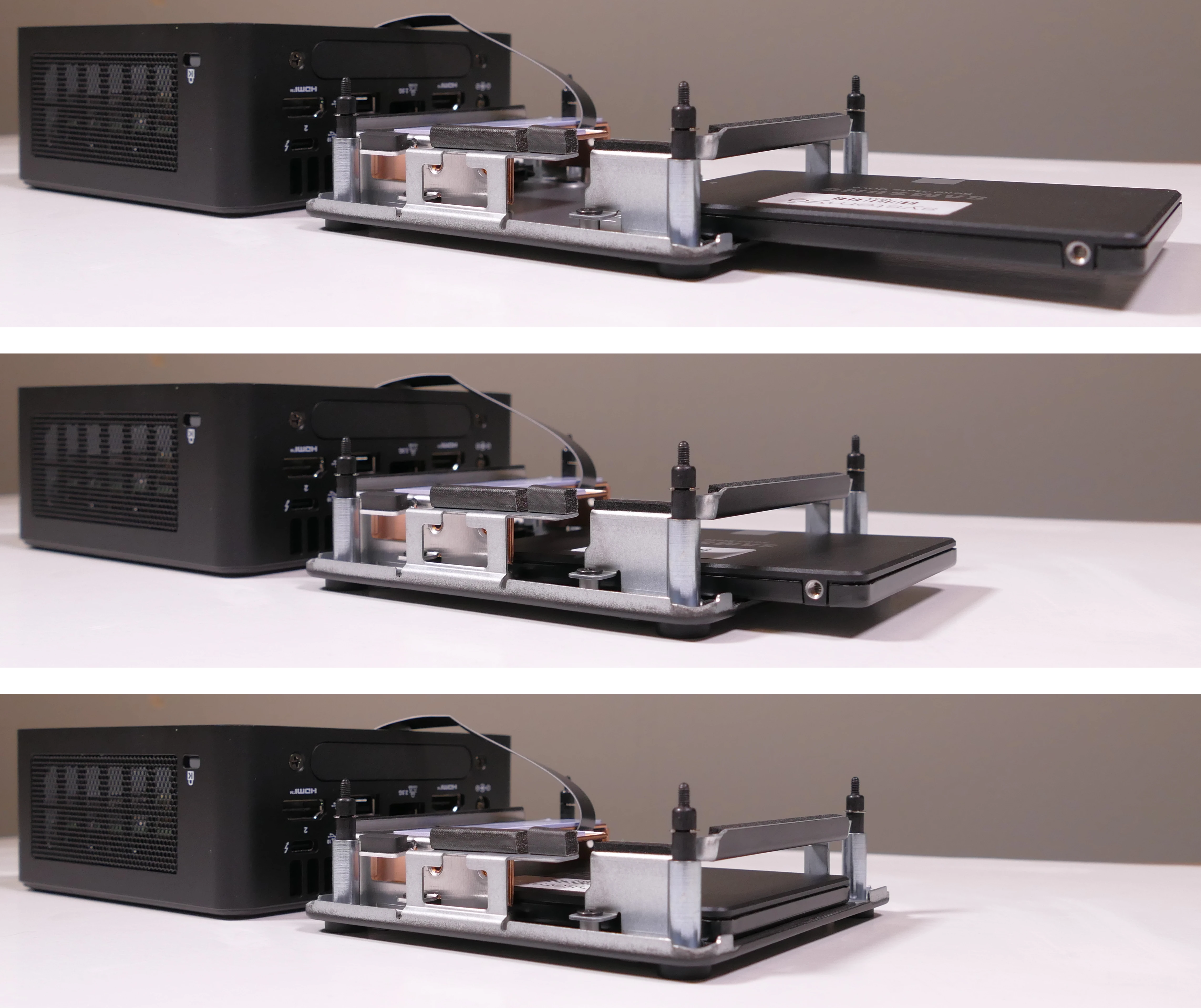
- Insert four 2.5" drive screws through the bottom panel to secure the 2.5" drive.

- Replace the bottom panel.
Resetting the CMOS:
A CMOS reset will restore the UEFI firmware settings to their factory defaults, which can sometimes help if the system is not booting.
Tools required: Cross-head (Phillips) screwdriver and (optionally) tweezers
Time estimate: 13 minutes
Difficulty: Medium ●
Steps to reset CMOS:
- Follow the steps above to remove the bottom panel and remove the M.2 drive.
- Disconnect the CMOS battery connector (labeled
RTCBATon the motherboard).- Try to pull the plug, not the wires.

- Hold down the power button for at least 15 seconds to discharge any residual energy in the system.
- Reconnect the CMOS battery.
- Replace the M.2 drive and bottom panel.
- Power up the machine. The system may take longer than usual to boot; this is normal behavior when the CMOS has been reset.
Replacing the wireless card:
Your Meerkat's WiFi and Bluetooth are both handled by the same module. It is a standard M.2 2230 slot with PCIe and USB interfaces (E-key).
Tools required: Cross-head (Phillips) screwdriver, 5.0 mm hex socket
Time estimate: 15 minutes
Difficulty: Medium ●
Steps to replace the WiFi/Bluetooth module:
- Follow the steps above to remove the bottom panel and remove the M.2 drive.
- Gently remove the two antennas (highlighted cyan below) by pulling them up and away from the wireless card.

- Use the 5mm hex socket to remove the M.2 screw standoff, which also holds the wireless card in place.
- The wireless card will pop up at an angle. Remove the card from the M.2 slot.
- Insert the new wireless card into the M.2 slot at an angle.
- Replace the retaining standoff.
- Attach the two antennas by aligning the circular fittings and pressing onto the wireless card. The connectors will snap into place.
- Use caution when attaching the connectors; the pins can bend, break, or snap.
Removing the optional I/O add-on:
The optional I/O add-on is an expansion module that adds one additional 2.5-Gigabit Ethernet port and two additional USB 2.0 Type-A ports to the system.
If you ordered your Meerkat with this module, the steps below can be used to remove it. If you're upgrading your Meerkat with the module, reverse the steps to install it.
Tools required: Cross-head (Phillips) screwdriver
Time estimate: 15 minutes
Difficulty: Medium ●
Steps to remove the optional I/O add-on:
- Follow the steps above to remove the bottom panel.
- Disconnect the module's ribbon cable by flipping the black latches up and pulling the ribbon out of the connectors on either side.
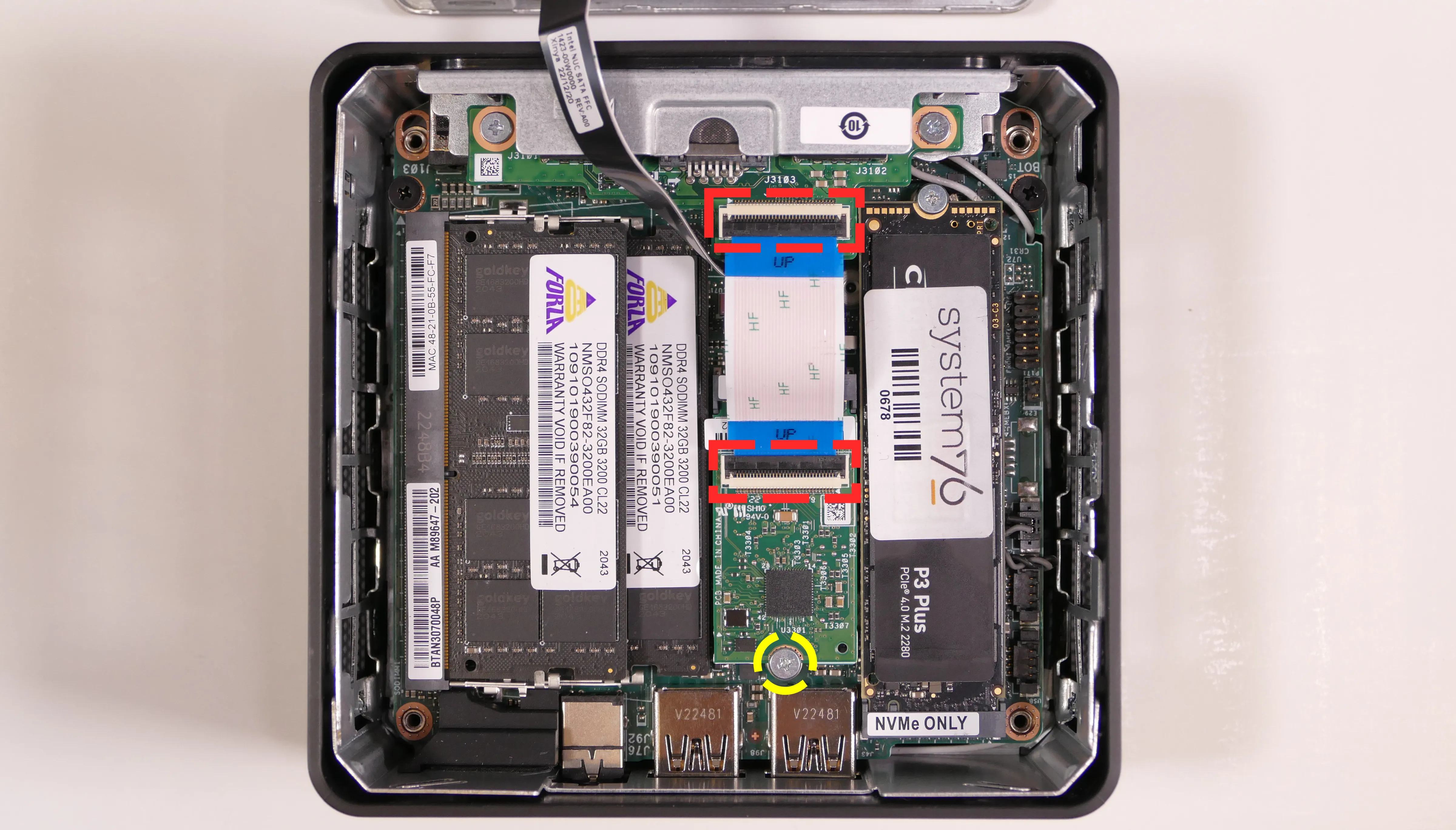
- Unscrew the M.2 screw holding the expansion module's adapter into the M.2 2242 slot and remove the adapter.
- Unscrew the two screws holding the expansion module in from the back of the system.

- Lift the expansion module out of the system.
- When reinstalling the expansion module, the side labeled
BTMshould face outwards (so it will point down towards the bottom of the machine once the system is upright).
- When reinstalling the expansion module, the side labeled
Steps to remove the expansion slot placeholder:
- Follow the steps above to remove the bottom panel.
- Unscrew the two screws holding the expansion slot placeholder in from the back of the system.

- Lift the expansion slot placeholder out of the system.
- When reinstalling the slot placeholder, the side labeled
BTMshould face outwards (so it will point down towards the bottom of the machine once the system is upright).
- When reinstalling the slot placeholder, the side labeled
Removing the motherboard:
Removing the motherboard is necessary for replacing the CMOS battery, cooling fan, and thermal paste.
Tools required: Cross-head (Phillips) screwdriver
Time estimate: 20 minutes
Difficulty: High ●
Steps to remove the motherboard:
- Follow the steps above to remove the bottom panel and remove the M.2 drive.
- If your Meerkat is the tall variety:
- Remove the optional I/O add-on or expansion slot placeholder.
- Disconnect the ribbon cable that leads to the 2.5" drive bay.
- The white latch pulls away from the motherboard to free the cable; gently pull the cable out of the connector.
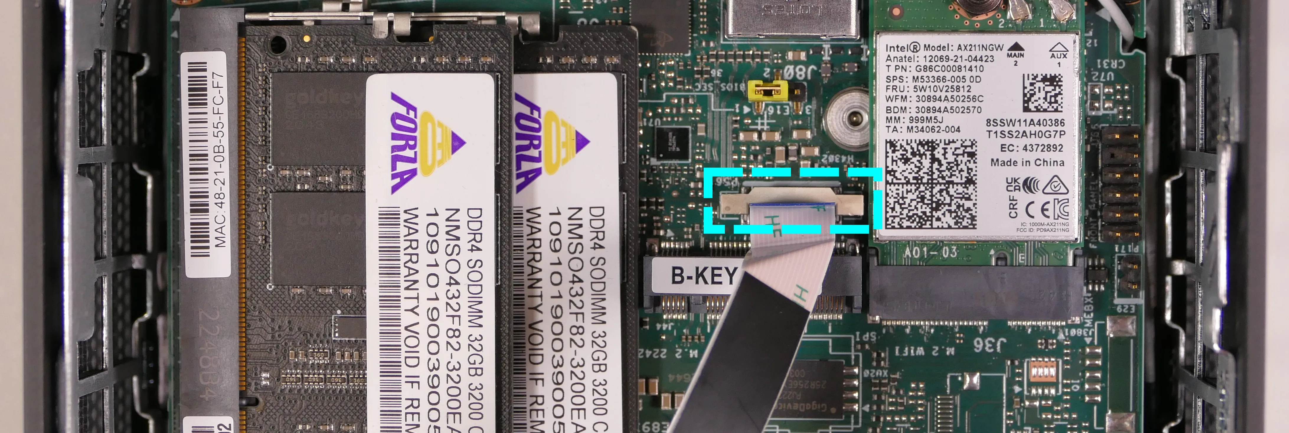
- Disconnect the two wireless antenna cables.
- Remove the two motherboard mounting screws along the back edge of the machine.

- Carefully lift the motherboard out of the case.
- It is easiest to lift the front side first, pivoting the board against the back side of the case.
- Removing the RAM is not required, but can make removing the motherboard easier.
- Slightly squeezing the front sides of the chassis can help provide more clearance while pivoting the motherboard.
Replacing the fan:
The cooling fan can be removed to clean dust out of the cooling system or to access the CPU heatsink when replacing the thermal paste.
The fan is an AVC BAZC0810R5HY006. The screws used for the fan are the same type as those used for the M.2 SSDs.
Tools required: Cross-head (Phillips) screwdriver
Time estimate: 25 minutes
Difficulty: High ●
Steps to replace the fan:
- Follow the steps above to remove the bottom panel, remove the M.2 drive, unplug the wireless card, and remove the motherboard.
- Unplug the fan connector, highlighted cyan below.
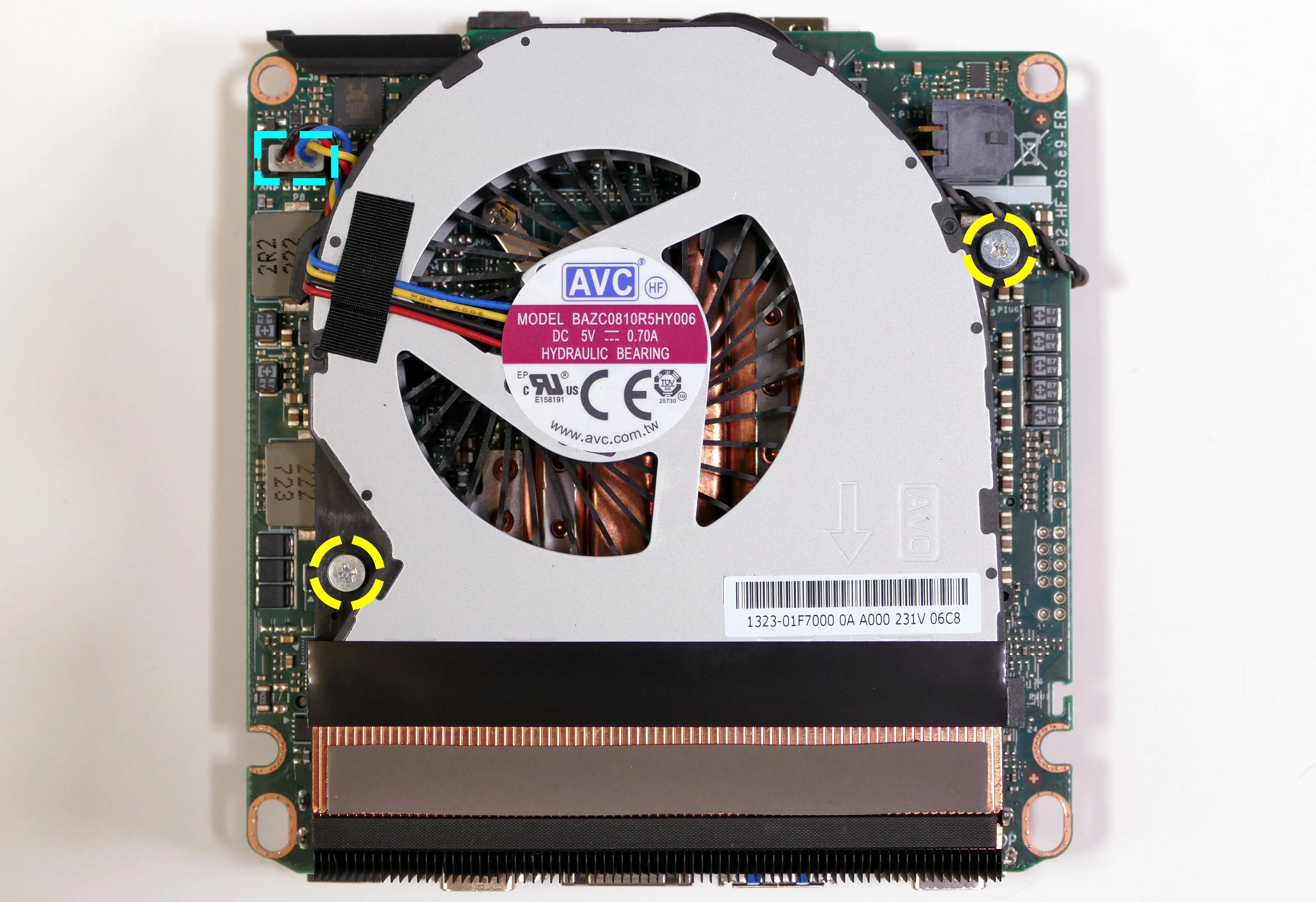
- Remove the two fan screws (highlighted yellow above) and remove the fan.
- The plastic strip at the bottom of the fan is adhered to the heatsink; gently pull the fan off of the heatsink.
Replacing the CMOS battery:
The CMOS battery supplies power to the system's CMOS chip, where UEFI settings and the computer's hardware clock are stored. If your clock is constantly resetting, your CMOS battery may need to be replaced.
Warning (ingestion hazard): Keep batteries out of reach of children. Death or serious injury can occur if ingested. If a battery is suspected to be swallowed or inserted inside any part of the body, seek immediate medical attention. In the US, you can also call the National Battery Ingestion Hotline for guidance: 1 (800) 498-8666
Tools required: Cross-head (Phillips) screwdriver
Time estimate: 27 minutes
Difficulty: High ●
Steps to replace the CMOS battery:
- Follow the steps above to remove the bottom panel, remove the motherboard, remove the fan, and unplug the CMOS battery.
- The CMOS battery is adhered to the motherboard with double-sided tape. Gently pull the CMOS battery off of the motherboard.

- Stick the new CMOS battery onto the motherboard using the included double-sided tape (if present), then plug the new CMOS battery in and replace the fan, motherboard, and bottom panel.
Replacing the thermal paste:
Thermal paste helps facilitate heat transfer between the CPU and the cooling equipment. Depending on your climate and the age of the machine, replacing the thermal paste between the CPU and the heatsink may help the system run cooler.
Tools required: Cross-head (Phillips) screwdriver
Time estimate: 30 minutes
Difficulty: High ●
Steps to replace the thermal paste:
- Follow the steps above to remove the bottom panel, remove the M.2 drive, unplug the wireless card, remove the motherboard, and remove the fan.
- Loosen the four heatsink screws in the order of the stamped numbers, starting with #1, then #2, #3, and #4.
- The screws are attached and will not completely separate from the heatsink.

- Gently lift the heatsink off of the motherboard.
- Using a paper towel, clean the old thermal paste off of the heatsink and CPU. You may also use a small amount of rubbing alcohol if the old paste is dried or difficult to remove.

- Apply a small line of thermal paste directly onto the CPU chip.

- Replace the heatsink and tighten the four screws in the order, starting with #1, then #2, #3, and #4.
- Reinstall the fan, motherboard, wireless card, M.2 drive, and bottom panel.
Removing the cable keeper:
Your Meerkat comes with a cable organizer to help hold cables in place. The cable organizer can be removed for a lower profile.
Tools required: Cross-head (Phillips) screwdriver (optional)
Time estimate: 1 minute
Difficulty: Easy ●
Steps to remove the cable keeper:
- Unscrew the Phillips thumbscrew holding the cable keeper in place.

Removing the top cover:
The Meerkat's top cover can be removed or replaced.
Tools required: None
Time estimate: 1 minute
Difficulty: Easy ●
Steps to remove the top cover:
- Pull up on the grooves in the back of the cover.
- A flat tool can optionally be used to help pry the cover away from the rest of the chassis.
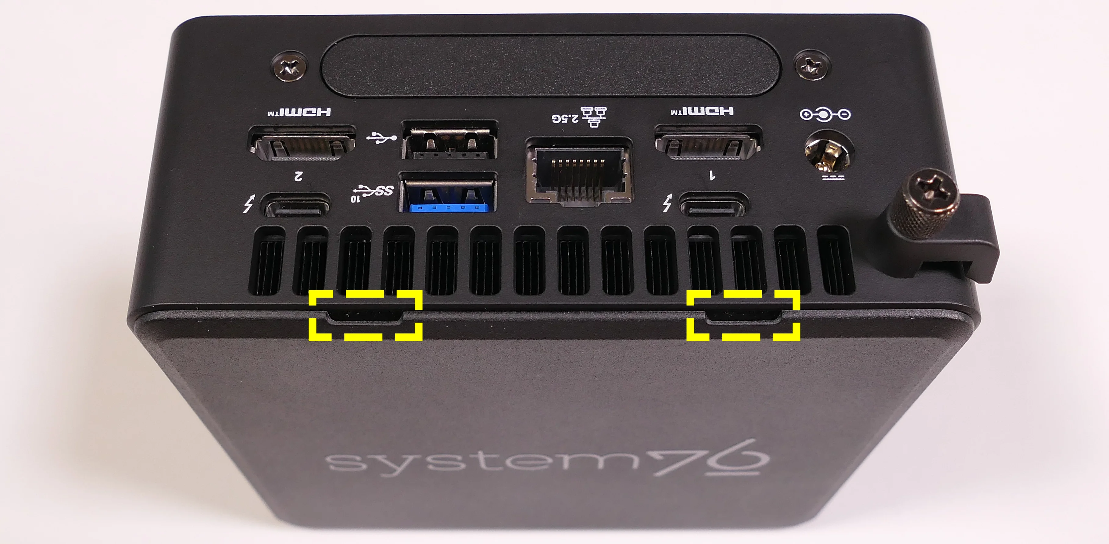
- Once the back is free, pull the rest of the top cover off of the machine.
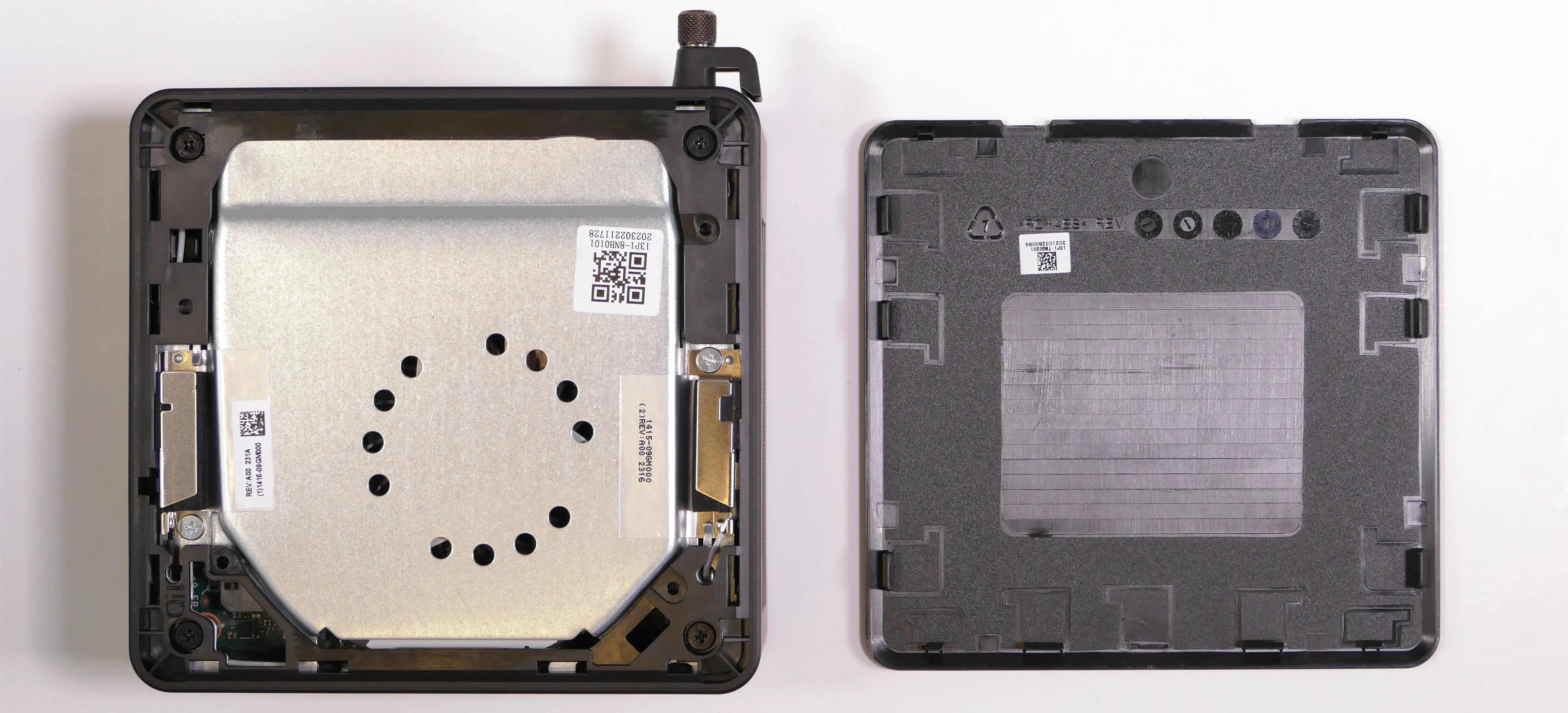
Mounting with VESA Mount:
Your Meerkat comes with a VESA mount adapter, which allows it to be mounted on the back of a display. This allows operation as an all-in-one, taking up no additional desk space.
Because the Meerkat mounts to the display's VESA mount, this will only work on displays which aren't already mounted via the VESA mount.
Tools required: Cross-head (Phillips) screwdriver
Time estimate: 10 minutes
Difficulty: Easy ●
Steps to mount with the VESA adapter:
- Insert the two shoulder screws into the bottom of the Meerkat.

- Use the remaining four screws to attach the VESA mounting plate, using the arrow to guide the orientation.

- Insert the two shoulder screws in the Meerkat into the two holes in the mounting plate (highlighted cyan above), then set the Meerkat down so it hangs on the mounting plate.
- The Meerkat can be mounted in either direction.

Meerkat (meer7)
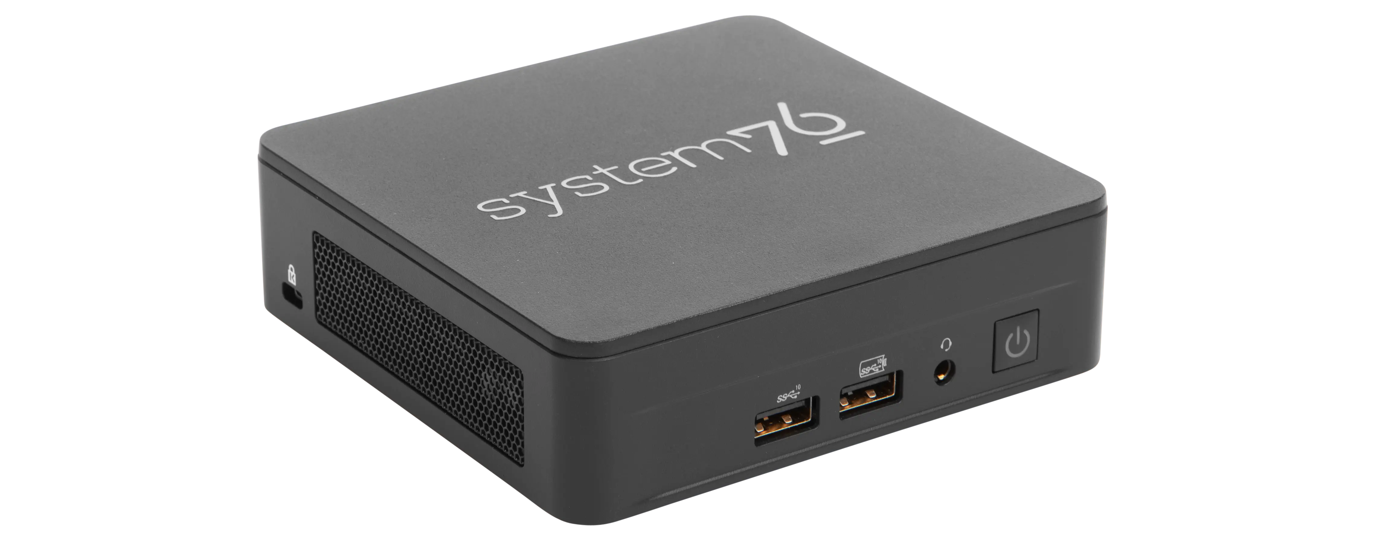
The System76 Meerkat is a desktop with the following specifications:
- CPU options
- Graphics
- GPU:
- i3 model: Intel UHD Graphics
- i5 & i7 model: Intel Iris Xe Graphics
- Video output:
- 2x HDMI 2.1
- 2x DisplayPort 1.4a over USB-C
- GPU:
- Memory
- Up to 64GB (2x32GB) Dual Channel DDR4 SODIMMs @ 3200 MHz
- Networking
- Power
- i3 model:
- 90W (19V, 4.74A) DC-in port
- Barrel size: 5.5mm (outer), 2.5mm (inner)
- Included AC adapter*: APD DA-90J19
- AC power cord type: IEC C5
- 90W (19V, 4.74A) DC-in port
- i5 and i7 models:
- 120W (20V, 6.0A) DC-in port
- Barrel size: 5.5mm (outer), 2.5mm (inner)
- Included AC adapter*: Chicony A17-120P2A
- AC power cord type: IEC C5
- 120W (20V, 6.0A) DC-in port
- * Included AC adapter may be a different model with the same specifications.
- i3 model:
- Sound
- 3.5mm headphone/microphone combo jack
- 7.1-channel digital audio output over HDMI and USB-C
- Storage
- 1x M.2 2280 (M key)
- PCIe NVMe Gen 4
- 1x M.2 2242 (B key)
- SATA III
- In the tall model, the optional I/O add-on occupies this slot.
- Tall model only: 1x 2.5"
- SATA III
- 1x M.2 2280 (M key)
- USB
- 2x USB4 Type-C with Thunderbolt 4
- 3x USB 3.2 Gen 2 Type-A
- 1x USB 2.0 Type-A
- Optional I/O add-on (tall model only): additional 2x USB 2.0 Type-A
- Dimensions
- Short: 117 x 112 x 37mm
- Tall: 117 x 112 x 54mm
Meerkat (External Overview)
Front side overview:

Left side overview:

Right side overview:

Back side overview:
Short model:

Tall model with optional I/O add-on:

Meerkat (Internal Overview)
Component overview:

- M.2 2280 (NVMe) SSD slot is highlighted in yellow
- M.2 2242 (SATA) SSD slot is highlighted in cyan
- Occupied by the optional I/O add-on (if installed) in the tall model
- 2.5" SATA ribbon connector is highlighted in green
- Only used in the tall model
- Wireless card (underneath the NVMe SSD) is highlighted in red
- RAM slots are highlighted in pink
- CMOS battery connector is highlighted in white
- Motherboard screws are highlighted in black
Meerkat (Parts & Repairs)
Several components in your Meerkat can be upgraded or replaced as necessary. Power the machine off and unplug all peripherals before working with any internal components. Then, follow these step-by-step guides for instructions:
- Removing the bottom panel
- Replacing an M.2 drive
- Replacing the RAM
- Adding/removing a 2.5" storage drive
- Resetting the CMOS
- Replacing the WiFi/Bluetooth module
- Removing the optional I/O add-on
- Removing the motherboard
- Replacing the fan
- Replacing the CMOS battery
- Replacing the thermal paste
- Removing the cable keeper
- Mounting with VESA mount
Removing the bottom panel:
The bottom panel can be removed to access the internal components.
Tools required: Cross-head (Phillips) screwdriver
Time estimate: 1 minute
Difficulty: Easy ●
Steps to remove the bottom panel:
- Place the machine lid-side down.
- Use a soft surface (such as a towel) to avoid scratches.
- Completely loosen the four screws in the corners.
- The screws are attached and will not completely separate from the bottom panel.
- Multiple sets of screws may be present on the tall model; the outermost screws (surrounded by rubber feet) are for the bottom panel.

- Gently lift the bottom panel out of the machine.
- If your Meerkat is the tall model (with a 2.5" drive slot), be careful not to damage the thin cable running from the motherboard to the bottom panel.
Replacing an M.2 drive:
Your Meerkat has two M.2 slots. The first slot is size 2280 and supports PCIe NVMe Gen 4. The second slot is size 2242 and supports SATA III.
If you have the tall model Meerkat with the optional I/O expansion module, it will occupy the 2242 slot.
Tools required: Cross-head (Phillips) screwdriver
Time estimate: 6 minutes
Difficulty: Easy ●
Steps to replace the M.2 drive:
- Follow the steps above to remove the bottom panel.
- Unscrew the retainer screw opposite the M.2 slot.
- In the photo below, the short model is shown on the left, while the tall model (with the optional I/O expansion module installed) is shown on the right.
- The 2280 slot screw is highlighted cyan, while the 2242 slot screw is highlighted red.

- Remove the existing M.2 drive by pulling it out of the slot.
- Insert the new M.2 drive into the slot and hold it in place.
- Replace the retainer screw.
- Replace the bottom panel.
Replacing the RAM:
The Meerkat 7 supports up to 64GB (2x32GB) of DDR4 SO-DIMMs running at 3200MHz. If you've purchased new RAM, need to replace your RAM, or are reseating your RAM, follow these steps.
Tools required: Cross-head (Phillips) screwdriver
Time estimate: 5 minutes
Difficulty: Easy ●
Steps to replace the RAM:
- Follow the steps above to remove the bottom panel.
- Pull the small tabs on both sides of the RAM away from the RAM stick simultaneously. The RAM should spring up to an angle.

- Remove the RAM from the slot.
- Insert the new RAM (or reseat the existing RAM) by placing it in the keyed slot and pressing down until it clicks into place.
Adding/removing a 2.5" storage drive:
If your Meerkat is the tall variety, it has a 2.5" SATA III drive bay built into the bottom panel.
Tools required: Cross-head (Phillips) screwdriver
Time estimate: 7 minutes
Difficulty: Easy ●
Steps to add/remove a 2.5" storage drive:
- If a 2.5" drive was not already installed, pull the four rubber plugs out of the bottom of the Meerkat.
- This can be done before or after opening the machine.

- Follow the steps above to remove the bottom panel.
- Locate the SATA connector in the bottom panel and orient your drive to match.

- Slide the drive into the slot on the bottom panel until it plugs all the way into its connector.

- Insert four 2.5" drive screws through the bottom panel to secure the 2.5" drive.

- Replace the bottom panel.
Resetting the CMOS:
A CMOS reset will restore the UEFI firmware settings to their factory defaults, which can sometimes help if the system is not booting.
Tools required: Cross-head (Phillips) screwdriver and (optionally) tweezers
Time estimate: 13 minutes
Difficulty: Medium ●
Steps to reset CMOS:
- Follow the steps above to remove the bottom panel and remove the M.2 drive.
- Disconnect the CMOS battery connector (labeled
RTCBATon the motherboard).- Try to pull the plug, not the wires.

- Hold down the power button for at least 15 seconds to discharge any residual energy in the system.
- Reconnect the CMOS battery.
- Replace the M.2 drive and bottom panel.
- Power up the machine. The system may take longer than usual to boot; this is normal behavior when the CMOS has been reset.
Replacing the wireless card:
Your Meerkat's WiFi and Bluetooth are both handled by the same module. It is a standard M.2 2230 slot with PCIe and USB interfaces (E-key).
Tools required: Cross-head (Phillips) screwdriver, 5.0 mm hex socket
Time estimate: 15 minutes
Difficulty: Medium ●
Steps to replace the WiFi/Bluetooth module:
- Follow the steps above to remove the bottom panel and remove the M.2 drive.
- Gently remove the two antennas (highlighted cyan below) by pulling them up and away from the wireless card.

- Use the 5mm hex socket to remove the M.2 screw standoff, which also holds the wireless card in place.
- The wireless card will pop up at an angle. Remove the card from the M.2 slot.
- Insert the new wireless card into the M.2 slot at an angle.
- Replace the retaining standoff.
- Attach the two antennas by aligning the circular fittings and pressing onto the wireless card. The connectors will snap into place.
- Use caution when attaching the connectors; the pins can bend, break, or snap.
Removing the optional I/O add-on:
The optional I/O add-on is an expansion module that adds one additional 2.5-Gigabit Ethernet port and two additional USB 2.0 Type-A ports to the system.
If you ordered your Meerkat with this module, the steps below can be used to remove it. If you're upgrading your Meerkat with the module, reverse the steps to install it.
Tools required: Cross-head (Phillips) screwdriver
Time estimate: 15 minutes
Difficulty: Medium ●
Steps to remove the optional I/O add-on:
- Follow the steps above to remove the bottom panel.
- Disconnect the module's ribbon cable by flipping the black latches up and pulling the ribbon out of the connectors on either side.

- Unscrew the M.2 screw holding the expansion module's adapter into the M.2 2242 slot and remove the adapter.
- Unscrew the two screws holding the expansion module in from the back of the system.

- Lift the expansion module out of the system.
- When reinstalling the expansion module, the side labeled
BTMshould face outwards (so it will point down towards the bottom of the machine once the system is upright).
- When reinstalling the expansion module, the side labeled
Steps to remove the expansion slot placeholder:
- Follow the steps above to remove the bottom panel.
- Unscrew the two screws holding the expansion slot placeholder in from the back of the system.

- Lift the expansion slot placeholder out of the system.
- When reinstalling the slot placeholder, the side labeled
BTMshould face outwards (so it will point down towards the bottom of the machine once the system is upright).
- When reinstalling the slot placeholder, the side labeled
Removing the motherboard:
Removing the motherboard is necessary for replacing the CMOS battery, cooling fan, and thermal paste.
Tools required: Cross-head (Phillips) screwdriver
Time estimate: 20 minutes
Difficulty: High ●
Steps to remove the motherboard:
- Follow the steps above to remove the bottom panel and remove the M.2 drive.
- If your Meerkat is the tall variety:
- Remove the optional I/O add-on or expansion slot placeholder.
- Disconnect the ribbon cable that leads to the 2.5" drive bay.
- The white latch pulls away from the motherboard to free the cable; gently pull the cable out of the connector.

- Disconnect the two wireless antenna cables.
- Remove the two motherboard mounting screws along the back edge of the machine.

- Carefully lift the motherboard out of the case.
- It is easiest to lift the front side first, pivoting the board against the back side of the case.
- Removing the RAM is not required, but can make removing the motherboard easier.
- Slightly squeezing the front sides of the chassis can help provide more clearance while pivoting the motherboard.
Replacing the fan:
The cooling fan can be removed to clean dust out of the cooling system or to access the CPU heatsink when replacing the thermal paste.
The screws used for the fan are the same type as those used for the M.2 SSDs.
Tools required: Cross-head (Phillips) screwdriver
Time estimate: 25 minutes
Difficulty: High ●
Steps to replace the fan:
- Follow the steps above to remove the bottom panel, remove the M.2 drive, unplug the wireless card, and remove the motherboard.
- Unplug the fan connector, highlighted cyan below.

- Remove the two fan screws (highlighted yellow above) and remove the fan.
- The plastic strip at the bottom of the fan is adhered to the heatsink; gently pull the fan off of the heatsink.
Replacing the CMOS battery:
The CMOS battery supplies power to the system's CMOS chip, where UEFI settings and the computer's hardware clock are stored. If your clock is constantly resetting, your CMOS battery may need to be replaced.
Warning (ingestion hazard): Keep batteries out of reach of children. Death or serious injury can occur if ingested. If a battery is suspected to be swallowed or inserted inside any part of the body, seek immediate medical attention. In the US, you can also call the National Battery Ingestion Hotline for guidance: 1 (800) 498-8666
Tools required: Cross-head (Phillips) screwdriver
Time estimate: 27 minutes
Difficulty: High ●
Steps to replace the CMOS battery:
- Follow the steps above to remove the bottom panel, remove the motherboard, remove the fan, and unplug the CMOS battery.
- The CMOS battery is adhered to the motherboard with double-sided tape. Gently pull the CMOS battery off of the motherboard.

- Stick the new CMOS battery onto the motherboard using the included double-sided tape (if present), then plug the new CMOS battery in and replace the fan, motherboard, and bottom panel.
Replacing the thermal paste:
Thermal paste helps facilitate heat transfer between the CPU and the cooling equipment. Depending on your climate and the age of the machine, replacing the thermal paste between the CPU and the heatsink may help the system run cooler.
Tools required: Cross-head (Phillips) screwdriver
Time estimate: 30 minutes
Difficulty: High ●
Steps to replace the thermal paste:
- Follow the steps above to remove the bottom panel, remove the M.2 drive, unplug the wireless card, remove the motherboard, and remove the fan.
- Loosen the four heatsink screws in order, starting with #1, then #2, #3, and #4.
- The screws are attached and will not completely separate from the heatsink.

- Gently lift the heatsink off of the motherboard.
- Using a paper towel, clean the old thermal paste off of the heatsink and CPU. You may also use a small amount of rubbing alcohol if the old paste is dried or difficult to remove.

- Apply a small line of thermal paste directly onto the CPU chip.

- Replace the heatsink and tighten the four screws in the order, starting with #1, then #2, #3, and #4.
- Reinstall the fan, motherboard, wireless card, M.2 drive, and bottom panel.
Removing the cable keeper:
Your Meerkat comes with a cable organizer to help hold cables in place. The cable organizer can be removed for a lower profile.
Tools required: Cross-head (Phillips) screwdriver (optional)
Time estimate: 1 minute
Difficulty: Easy ●
Steps to remove the cable keeper:
- Unscrew the Phillips thumbscrew holding the cable keeper in place.

Removing the top cover:
The Meerkat's top cover can be removed or replaced.
Tools required: None
Time estimate: 1 minute
Difficulty: Easy ●
Steps to remove the top cover:
- Pull up on the grooves in the back of the cover.

- Once the back is free, pull the rest of the top cover off of the machine.

Mounting with VESA Mount:
Your Meerkat comes with a VESA mount adapter, which allows it to be mounted on the back of a display. This allows operation as an all-in-one, taking up no additional desk space.
Because the Meerkat mounts to the display's VESA mount, this will only work on displays which aren't already mounted via the VESA mount.
Tools required: Cross-head (Phillips) screwdriver
Time estimate: 10 minutes
Difficulty: Easy ●
Steps to mount with the VESA adapter:
- Insert the two shoulder screws into the bottom of the Meerkat.

- Use the remaining four screws to attach the VESA mounting plate, using the arrow to guide the orientation.

- Insert the two shoulder screws in the Meerkat into the two holes in the mounting plate (highlighted cyan above), then set the Meerkat down so it hangs on the mounting plate.
- The Meerkat can be mounted in either direction.

Meerkat (meer6)
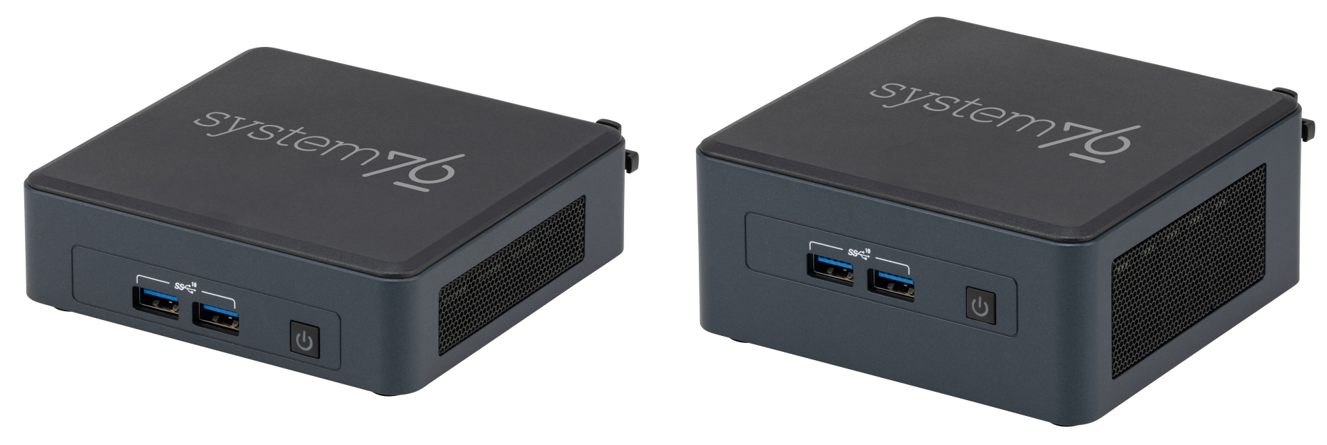
The System76 Meerkat is a desktop with the following specifications:
- CPU options
- Graphics
- GPU: Intel UHD Graphics
- Video output:
- 2x HDMI 2.0b
- 2x DisplayPort 1.4a over USB-C
- Memory
- Up to 64GB (2x32GB) Dual Channel DDR4 SODIMMs @ 3200 MHz
- Networking
- Power
- i3 model:
- 90W (19V, 4.74A) DC-in port
- Barrel size: 5.5mm (outer), 2.5mm (inner)
- Included AC adapter*: APD DA-90J19
- AC power cord type: IEC C5
- 90W (19V, 4.74A) DC-in port
- i5 and i7 models:
- 120W (19V, 6.32A) DC-in port
- Barrel size: 5.5mm (outer), 2.5mm (inner)
- Included AC adapter*: FSP FSP120-ABBN3
- AC power cord type: IEC C5
- 120W (19V, 6.32A) DC-in port
- * Included AC adapter may be a different model with the same specifications.
- i3 model:
- Sound
- 7.1-channel digital audio output over HDMI and USB-C
- Storage
- 1x M.2 2280 (M key)
- PCIe NVMe Gen 4
- 1x M.2 2242 (B key)
- SATA III
- Tall model only: 1x 2.5"
- SATA III
- 1x M.2 2280 (M key)
- USB
- 1x USB4 Type-C with Thunderbolt 4
- 1x USB4 Type-C with Thunderbolt 3
- 3x USB 3.2 Gen 2 Type-A
- 1x USB 2.0 Type-A
- Dimensions
- Short: 117 x 112 x 38mm
- Tall: 117 x 112 x 51mm
Meerkat (External Overview)
Short meer6:
Front side overview:

Back side overview:

Left side overview:

Right side overview:

Tall meer6:
Front side overview:
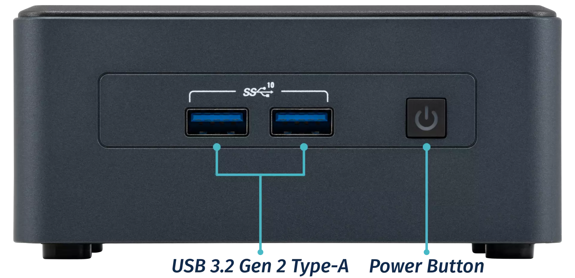
Back side overview:

Left side overview:
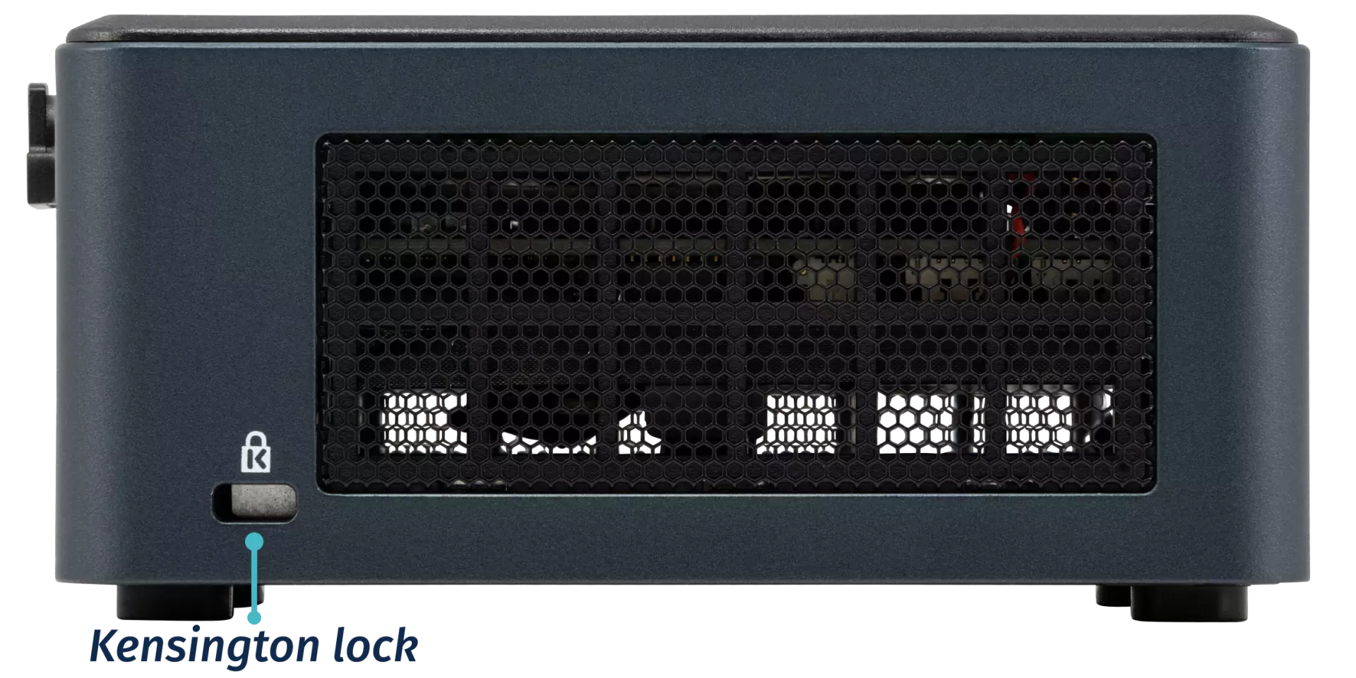
Right side overview:
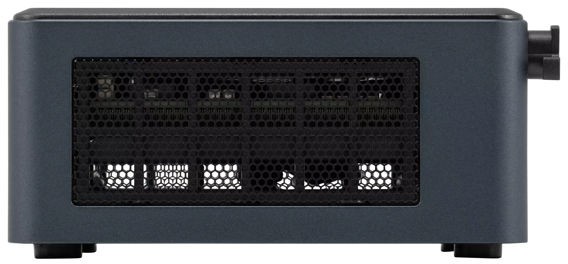
Meerkat (Internal Overview)
Component overview:

- M.2 2280 (NVMe) SSD slot is highlighted in yellow
- M.2 2242 (SATA) SSD slot is highlighted in cyan
- Wireless card (underneath the NVMe SSD) is highlighted in red
- RAM slots are highlighted in pink
- CMOS battery connector is highlighted in white
Meerkat (Parts & Repairs)
Several components in your Meerkat can be upgraded or replaced as necessary. Power the machine off and unplug all peripherals before working with any internal components. Then, follow these step-by-step guides for instructions:
- Removing the bottom panel
- Replacing an M.2 drive
- Replacing the RAM
- Adding/removing a 2.5" storage drive
- Resetting the CMOS
- Replacing the WiFi/Bluetooth module
- Removing the motherboard
- Replacing the fan
- Replacing the CMOS battery
- Replacing the thermal paste
- Removing the cable keeper
- Mounting with VESA mount
Removing the bottom panel:
The bottom panel can be removed to access the internal components.
Tools required: Cross-head (Phillips) screwdriver
Time estimate: 1 minute
Difficulty: Easy ●
Steps to remove the bottom panel:
- Place the machine lid-side down.
- Use a soft surface (such as a towel) to avoid scratches.
- Completely loosen the four screws in the corners.
- The screws are attached and will not completely separate from the bottom panel.

- Gently lift the bottom panel out of the machine.
- If your Meerkat is the tall model (with 2.5" drive slot), be careful not to damage the thin cable running from the motherboard to the bottom panel.
Replacing an M.2 drive:
Your Meerkat has two M.2 slots. The first slot is size 2280 and supports PCIe NVMe Gen 4. The second slot is size 2242 and supports SATA III.
Tools required: Cross-head (Phillips) screwdriver
Time estimate: 6 minutes
Difficulty: Easy ●
Steps to replace the M.2 drive:
- Follow the steps above to remove the bottom panel.
- Unscrew the retainer screw opposite the M.2 slot.

- Remove the existing M.2 drive by pulling it out of the slot.
- Insert the new M.2 drive into the slot and hold it in place.
- Replace the retainer screw.
- Replace the bottom panel.
Replacing the RAM:
The Meerkat 6 supports up to 64GB (2x32GB) of DDR4 SO-DIMMs running at 3200MHz. If you've purchased new RAM, need to replace your RAM, or are reseating your RAM, follow these steps.
Tools required: Cross-head (Phillips) screwdriver
Time estimate: 5 minutes
Difficulty: Easy ●
Steps to replace the RAM:
- Follow the steps above to remove the bottom panel.
- Press the small tabs on both sides of the RAM simultaneously. The RAM should spring up to an angle.

- Remove the RAM from the slot.
- Insert the new RAM (or reseat the existing RAM) by placing it in the keyed slot and pressing down until it clicks into place.
Adding/removing a 2.5" storage drive:
If your Meerkat is the tall variety, it has a 2.5" SATA III drive bay built into the bottom panel.
Tools required: Cross-head (Phillips) screwdriver
Time estimate: 7 minutes
Difficulty: Easy ●
Steps to add/remove a 2.5" storage drive:
- Follow the steps above to remove the bottom panel.
- Locate the SATA connector in the bottom panel and orient your drive to match.
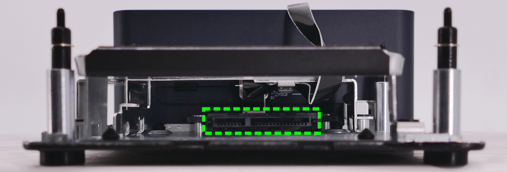
- Slide the drive into the slot on the bottom panel until it plugs all the way into its connector.
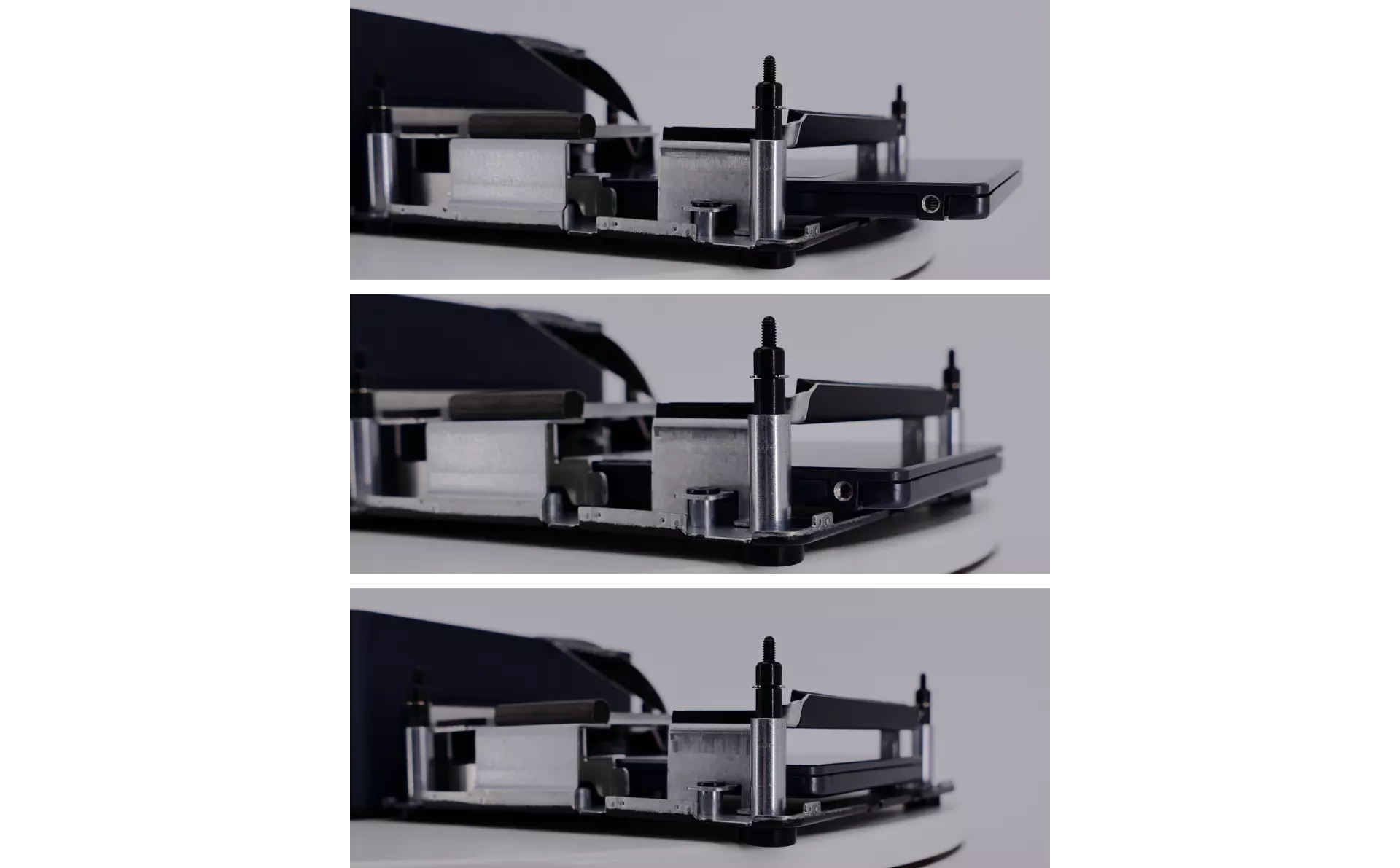
- Replace the bottom panel.
Resetting the CMOS:
A CMOS reset will restore the UEFI firmware settings to their factory defaults, which can sometimes help if the system is not booting.
Tools required: Cross-head (Phillips) screwdriver and (optionally) tweezers
Time estimate: 13 minutes
Difficulty: Medium ●
Steps to reset CMOS:
- Follow the steps above to remove the bottom panel and remove the M.2 drive.
- Disconnect the CMOS battery connector.
- Try to pull the plug, not the wires.

- Hold down the power button for at least 15 seconds to discharge any residual energy in the system.
- Reconnect the CMOS battery.
- Replace the M.2 drive and bottom panel.
- Power up the machine. The system may take longer than usual to boot; this is normal behavior when the CMOS has been reset.
Replacing the wireless card:
Your Meerkat's WiFi and Bluetooth are both handled by the same module. It is a standard M.2 2230 slot with PCIe and USB interfaces (E-key).
Tools required: Cross-head (Phillips) screwdriver, 5.0 mm hex socket
Time estimate: 15 minutes
Difficulty: Medium ●
Steps to replace the WiFi/Bluetooth module:
- Follow the steps above to remove the bottom panel and remove the M.2 drive.
- Gently remove the two antennas (highlighted cyan below) by pulling them up and away from the wireless card.

- Use the 5mm hex socket to remove the M.2 screw standoff, which also holds the wireless card in place.
- The wireless card will pop up at an angle. Remove the card from the M.2 slot.
- Insert the new wireless card into the M.2 slot at an angle.
- Replace the retaining standoff.
- Attach the two antennas by aligning the circular fittings and pressing onto the wireless card. The connectors will snap into place.
- Use caution when attaching the connectors; the pins can bend, break, or snap.
Removing the motherboard:
Removing the motherboard is necessary for replacing the CMOS battery, cooling fan, and thermal paste.
Tools required: Cross-head (Phillips) screwdriver
Time estimate: 20 minutes
Difficulty: High ●
Steps to remove the motherboard:
- Follow the steps above to remove the bottom panel and remove the M.2 drive.
- If your Meerkat is the tall variety, disconnect the ribbon cable that leads to the 2.5" drive bay.
- The white latch pulls away from the motherboard to free the cable; gently pull the cable out of the connector.

- Disconnect the two wireless antenna cables.
- Remove the two motherboard mounting screws along the back edge of the machine.

- Carefully lift the motherboard out of the case.
- It is easiest to lift the front side first, pivoting the board against the back side of the case.
- Removing the RAM is not required, but can make removing the motherboard easier.
Replacing the fan:
The cooling fan can be removed to clean dust out of the cooling system or to access the CPU heatsink when replacing the thermal paste.
Tools required: Cross-head (Phillips) screwdriver
Time estimate: 25 minutes
Difficulty: High ●
Steps to replace the fan:
- Follow the steps above to remove the motherboard.
- Unplug the fan connector, highlighted cyan below.
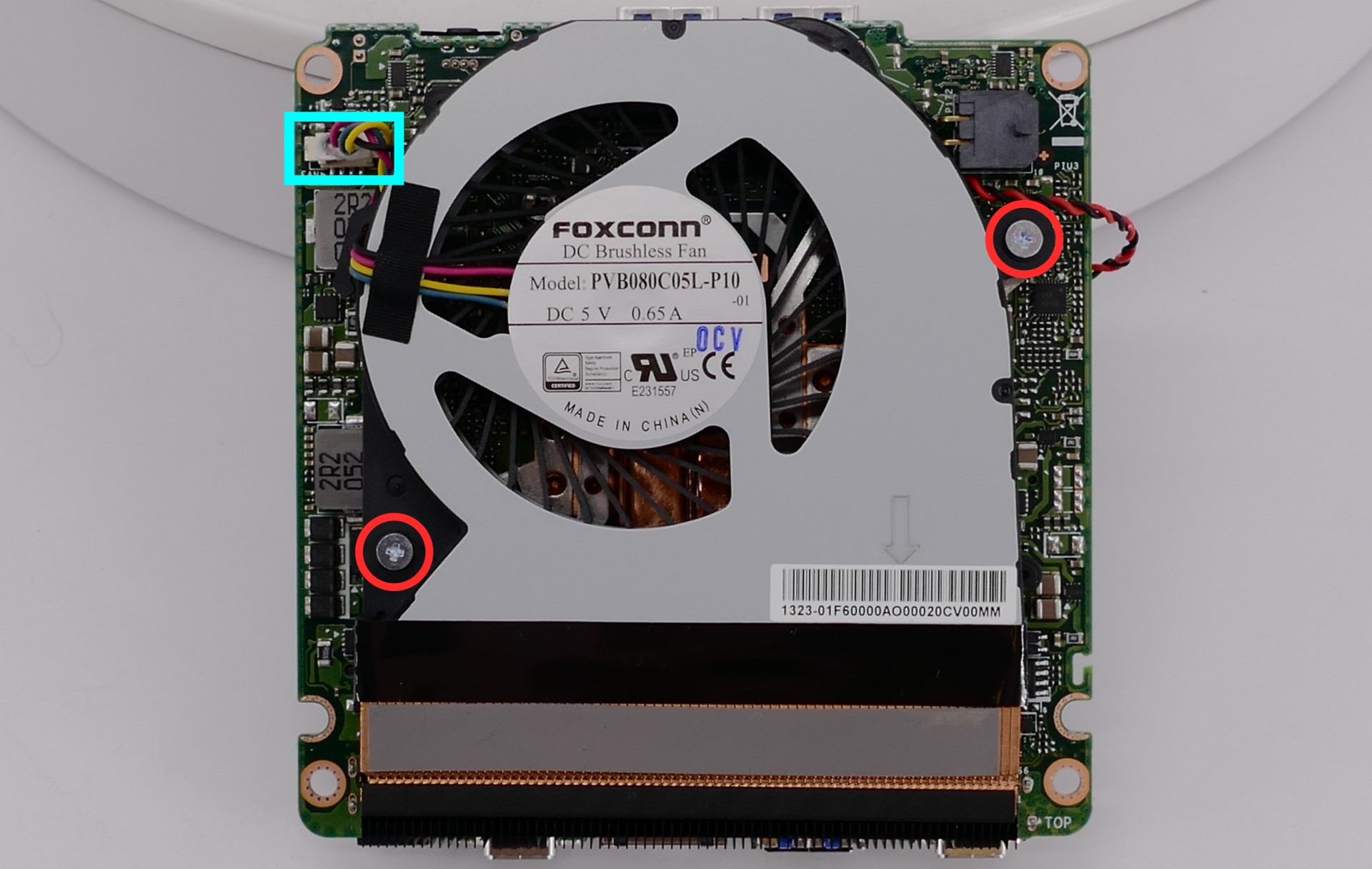
- Remove the two fan screws (highlighted red above) and remove the fan.
- The plastic strip at the bottom of the fan is adhered to the heatsink; gently pull the fan off of the heatsink.
Replacing the CMOS battery:
The CMOS battery supplies power to the system's CMOS chip, where UEFI settings and the computer's hardware clock are stored. If your clock is constantly resetting, your CMOS battery may need to be replaced.
Warning (ingestion hazard): Keep batteries out of reach of children. Death or serious injury can occur if ingested. If a battery is suspected to be swallowed or inserted inside any part of the body, seek immediate medical attention. In the US, you can also call the National Battery Ingestion Hotline for guidance: 1 (800) 498-8666
Tools required: Cross-head (Phillips) screwdriver
Time estimate: 27 minutes
Difficulty: High ●
Steps to replace the CMOS battery:
- Follow the steps above to remove the bottom panel, remove the motherboard, remove the fan, and unplug the CMOS battery.
- The CMOS battery is adhered to the motherboard with double-sided tape. Gently pull the CMOS battery off of the motherboard.

- Stick the new CMOS battery onto the motherboard using the included double-sided tape (if present), then plug the new CMOS battery in and replace the fan, motherboard, and bottom panel.
Replacing the thermal paste:
Thermal paste helps facilitate heat transfer between the CPU and the cooling equipment. Depending on your climate and the age of the machine, replacing the thermal paste between the CPU and the heatsink may help the system run cooler.
Tools required: Cross-head (Phillips) screwdriver
Time estimate: 30 minutes
Difficulty: High ●
Steps to replace the thermal paste:
- Follow the steps above to remove the bottom panel, remove the M.2 drive, unplug the wireless card, remove the motherboard, and remove the fan.
- Loosen the four heatsink screws in order, starting with #1, then #2, #3, and #4.
- The screws are attached and will not completely separate from the heatsink.
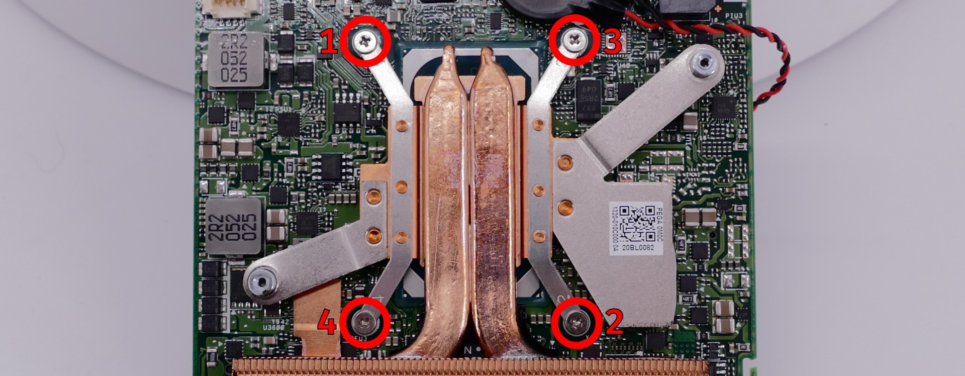
- Gently lift the heatsink off of the motherboard.
- Using a paper towel, clean the old thermal paste off of the heatsink and CPU. You may also use a small amount of rubbing alcohol if the old paste is dried or difficult to remove.

- Apply a small dot of thermal paste directly onto the CPU chip.

- Replace the heatsink and tighten the four screws in the order, starting with #1, then #2, #3, and #4.
- Reinstall the fan, motherboard, wireless card, M.2 drive, and bottom panel.
Removing the cable keeper:
Your Meerkat comes with a cable organizer to help hold cables in place. The cable organizer can be removed for a lower profile.
Tools required: Cross-head (Phillips) screwdriver
Time estimate: 1 minute
Difficulty: Easy ●
Steps to remove the cable keeper:
- Unscrew the Phillips screw holding the cable keeper in place.

Removing the top cover:
The Meerkat's top cover can be removed or replaced.
Tools required: None
Time estimate: 1 minute
Difficulty: Easy ●
Steps to remove the top cover:
- Pull up on the grooves in the back of the cover.

- Once the back is free, pull the rest of the top cover off of the machine.
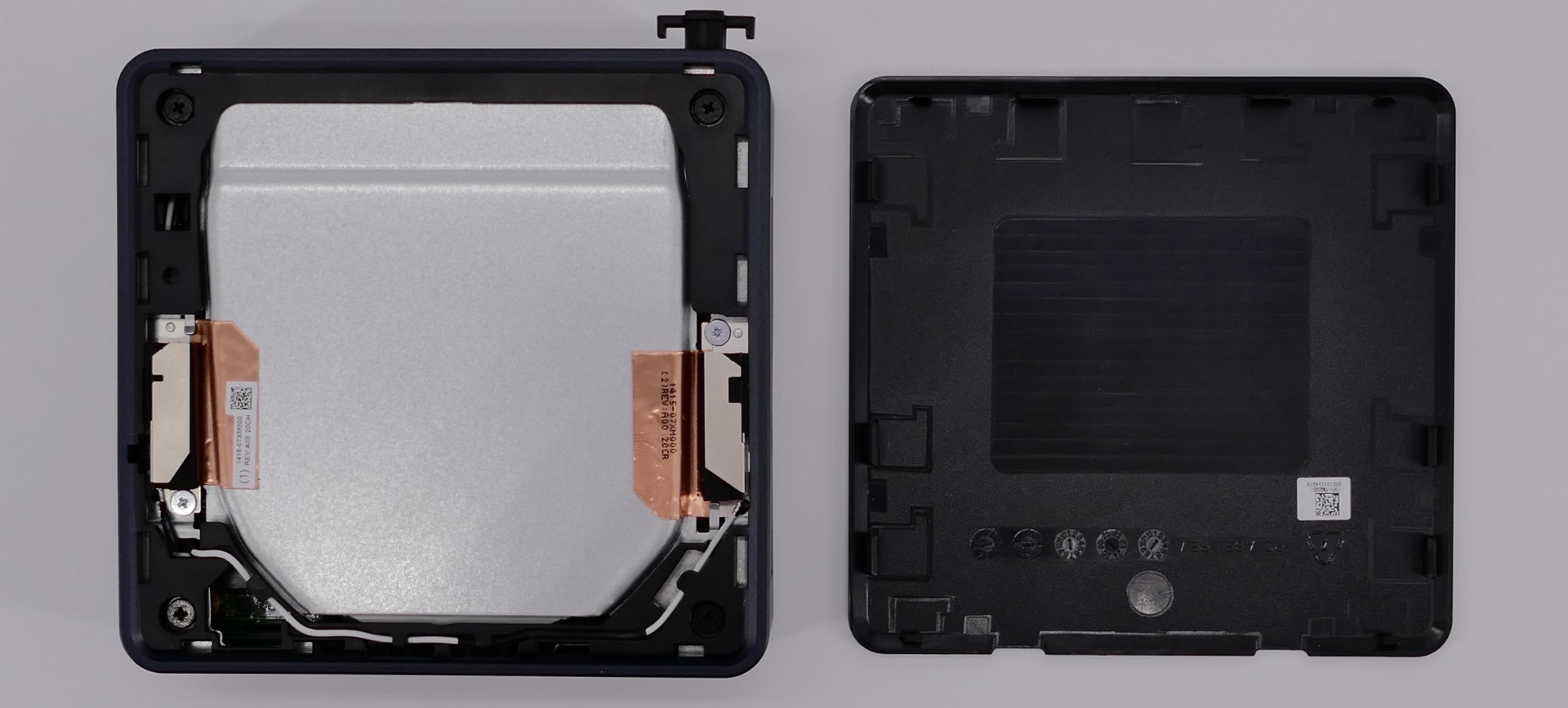
Mounting with VESA Mount:
Your Meerkat comes with a VESA mount adapter, which allows it to be mounted on the back of a display. Because it mounts to the display's VESA mount, this will only work on displays which aren't already mounted via the VESA mount.
Tools required: Cross-head (Phillips) screwdriver
Time estimate: 10 minutes
Difficulty: Easy ●
Steps to mount with the VESA adapter:
- Insert the two shoulder screws into the bottom of the Meerkat.
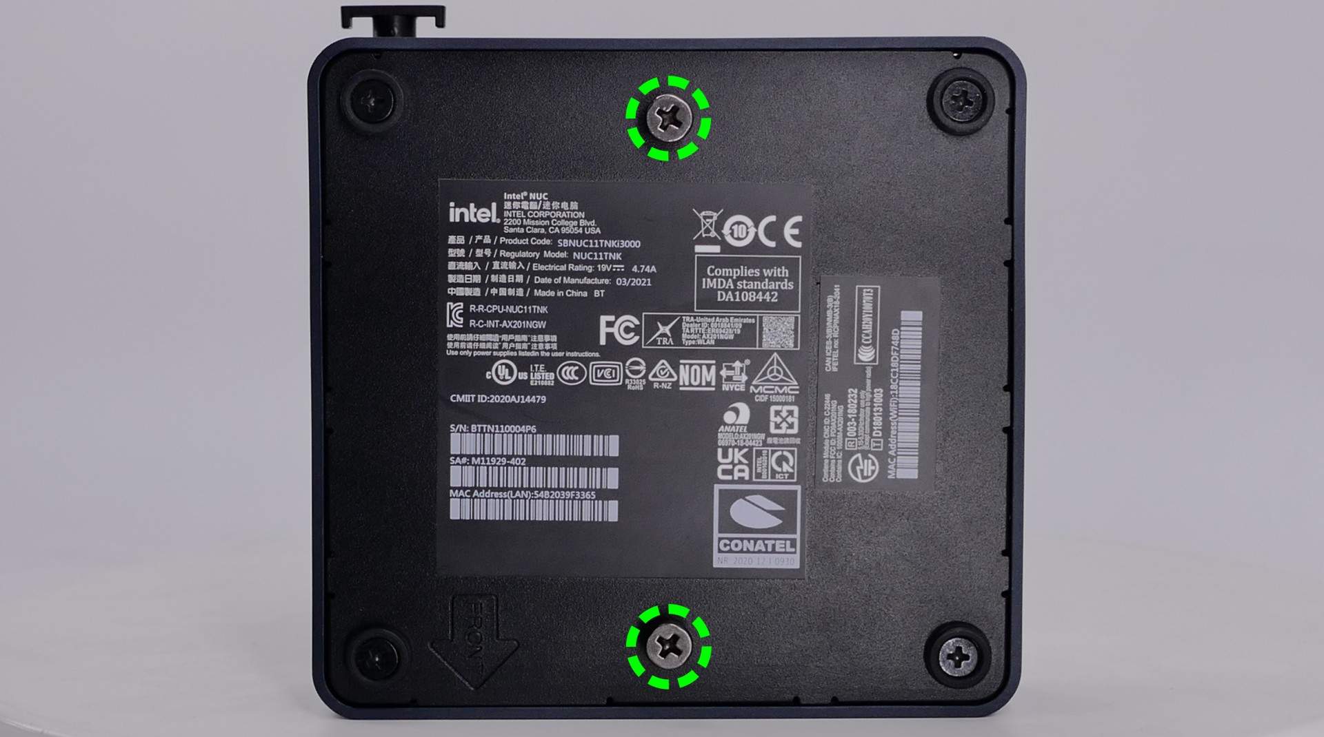
- Use the remaining four screws to attach the VESA mounting plate, using the arrow to guide the orientation.
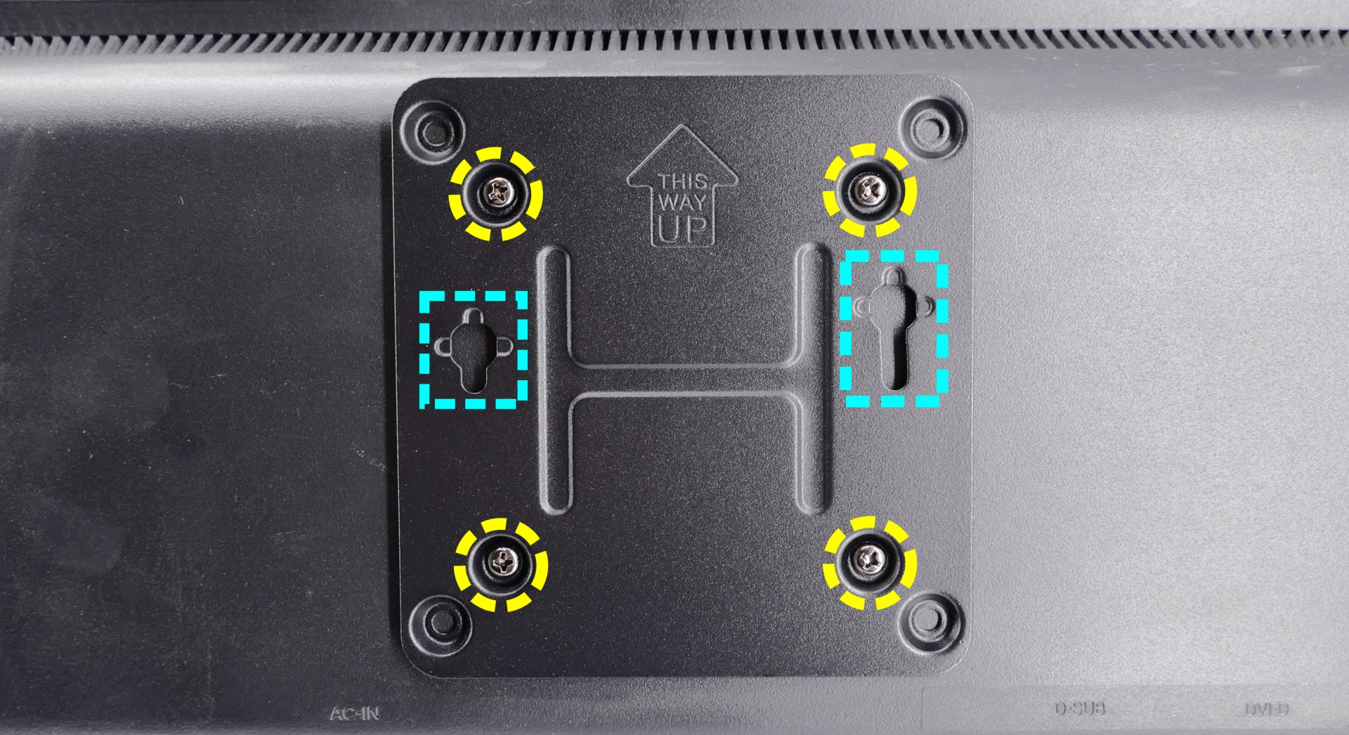
- Insert the two shoulder screws in the Meerkat into the two holes in the mounting plate (highlighted cyan above), then set the Meerkat down so it hangs on the mounting plate.
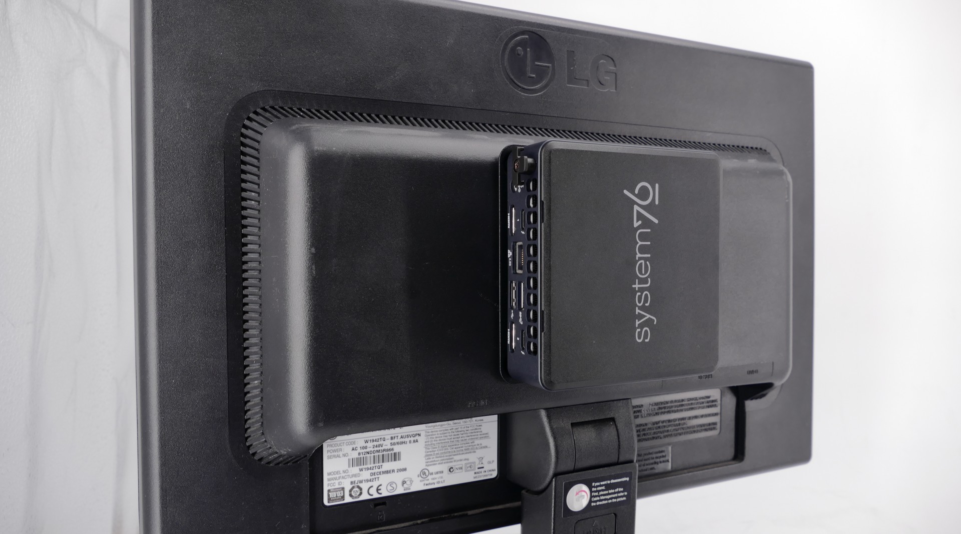
Meerkat (meer5)
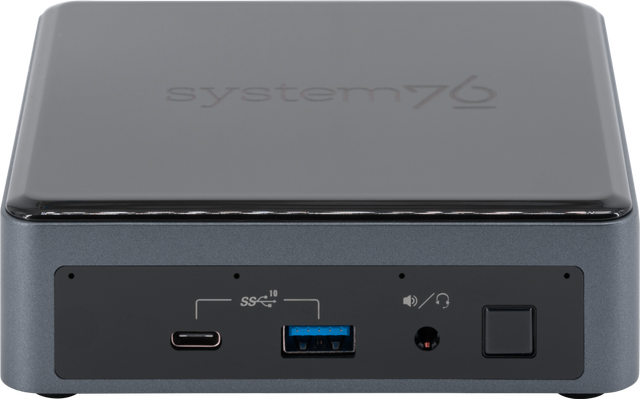
The System76 Meerkat is a desktop with the following specifications:
- CPU options
- Graphics
- GPU: Intel UHD Graphics
- Video output:
- 1x HDMI 2.0b
- 1x DisplayPort 1.2 over USB-C
- Memory
- Up to 64GB (2x32GB) Dual Channel DDR4 SODIMMs @ 2666 MHz
- Networking
- Power
- i3 and i5 models:
- 90W (19V, 4.74A) DC-in port
- Barrel size: 5.5mm (outer), 2.5mm (inner)
- Included AC adapter*: APD DA-90J19
- AC power cord type: IEC C5
- 90W (19V, 4.74A) DC-in port
- i7 model:
- 120W (19V, 6.32A) DC-in port
- Barrel size: 5.5mm (outer), 2.5mm (inner)
- Included AC adapter*: FSP FSP120-ABBN3
- AC power cord type: IEC C5
- 120W (19V, 6.32A) DC-in port
- * Included AC adapter may be a different model with the same specifications.
- i3 and i5 models:
- Sound
- 3.5mm line out/line in combo jack for headsets
- Newer meer5's do not have this port
- 7.1 digital out over HDMI and mDP
- Integrated front microphone
- 3.5mm line out/line in combo jack for headsets
- Storage
- 1x M.2 (PCIe NVMe or SATA)
- 1x 2.5" SATA (for Tall meer5 only)
- SD card reader
- USB
- 1x USB 3.1 Gen 2 Type-C
- 1x USB 3.1 Gen 2 Type-C with Thunderbolt 3
- 3x USB 3.1 Gen 2 Type-A
- Dimensions
- Short: 117 x 112 x 38mm
- Tall: 117 x 112 x 51mm
Meerkat (External Overview)
Short meer5:
Front side overview:
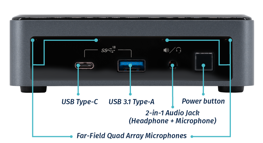 Note: newer meer5's may not have the 2-in-1 audio jack
Back side overview:
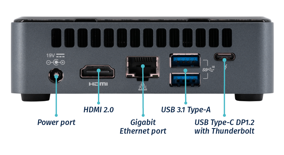
Left side overview:
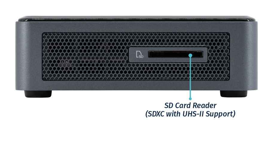
Right side overview:
Tall meer5:
Front side overview:
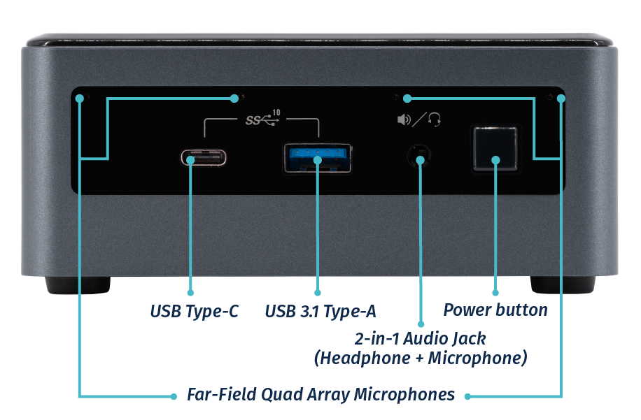 Note: newer meer5's may not have the 2-in-1 audio jack
Back side overview:
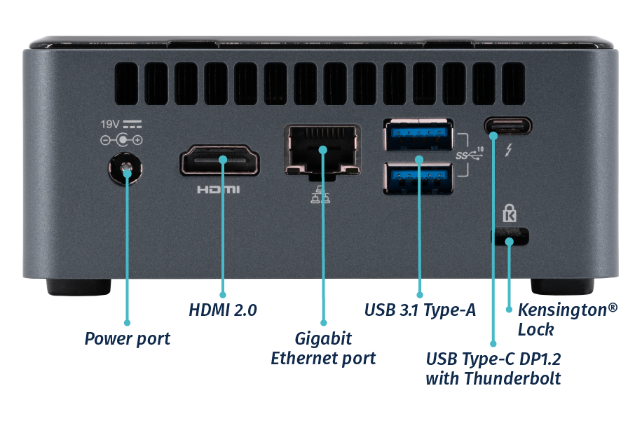
Left side overview:
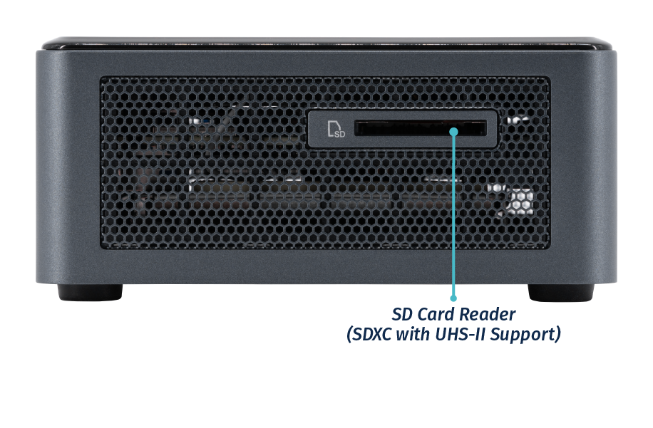
Meerkat (Internal Overview)
Component overview:
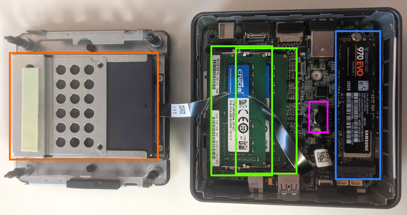
- RAM slots are highlighted in bright green
- M.2 SSD is highlighted in blue
- 2.5" drive bay (only present on Tall meer5) is highlighted in orange
- Front microphone connector is highlighted in pink
Meerkat (Parts & Repairs)
Several components in your Meerkat can be upgraded or replaced as necessary. Power the machine off and unplug all peripherals before working with any internal components. Then, follow these step-by-step guides for instructions:
- Removing the bottom panel
- Replacing the M.2 drive
- Replacing the RAM
- Adding/removing a 2.5" storage drive
- Resetting CMOS
- Removing the motherboard
- Removing the fan
- Replacing thermal paste
- Mounting with VESA mount
Removing the bottom panel:
The bottom panel can be removed to access the internal components.
Tools required: Cross-head (Phillips) screwdriver
Time estimate: 3 minutes
Difficulty: Easy ●
Steps to remove the bottom panel:
- Place the machine lid-side down.
- Use a soft surface (such as a towel) to avoid scratches.
- Completely loosen the four screws in the corners.
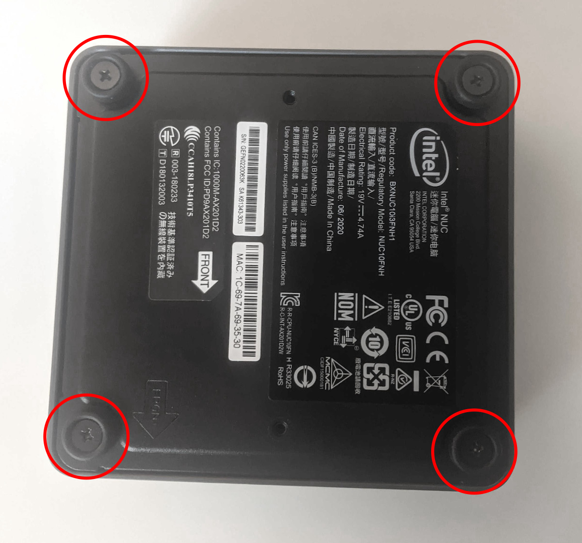
-
The screws are held captive in the bottom panel, so they will not come completely out of the machine, but once they are fully loose, you will be able to grab the screws and gently lift the bottom panel out of the machine.
If your Meerkat is the Tall variation, use caution when lifting the bottom panel off, as there is a thin cable that attaches to the drive bay in the bottom panel. The cable should be long enough that you can set the bottom panel next to the machine without having to disconnect it at the motherboard, as shown below:

If your Meerkat is the Short variation, you will have no such cable, allowing you to completely remove the bottom panel after the four screws are completely loosened.
Replacing the M.2 drive:
Your Meerkat has one M.2 slot, which supports either PCIe NVMe Gen 3 x4 or SATA III. The following M.2 sizes are supported: 2280 and 2242.
Tools required: Cross-head (Phillips) screwdriver
Time estimate: 10 minutes
Difficulty: Easy ●
Steps to replace the M.2 drive:
- Follow the steps above to remove the bottom panel.
- Unscrew the retainer screw on the end of the SSD opposite the M.2 slot.

- Remove the existing M.2 drive by pulling it out of the slot.
- Insert the new M.2 drive into the slot and hold it in place.
- Replace the retainer screw.
- Replace the bottom panel.
Replacing the RAM:
Your Meerkat supports up to 64GB (2x32GB) of RAM. The RAM sticks are DDR4 SODIMMs running at a speed of 2666MHz. If you've purchased new RAM, need to replace your RAM, or are re-seating your RAM, follow these steps.
Tools required: Cross-head (Phillips) screwdriver
Time estimate: 10 minutes
Difficulty: Easy ●
Steps to replace the RAM:
- Follow the steps above to remove the bottom panel.
- Since the RAM slots are stacked on your Meerkat, if you have two RAM sticks installed, the top one must be removed before you can access the one below it. To remove a RAM stick, both RAM latches need to be simultaneously pushed out and away from the edges of the RAM stick.
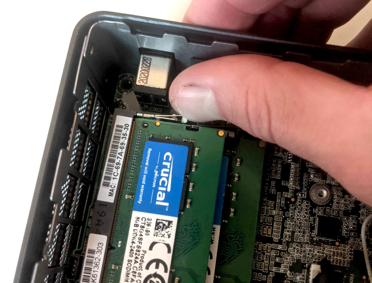
- Once both latches are released, the RAM stick will pop up, pushed by the spring tension from the RAM slot. This means the RAM stick can be pulled backwards out of the slot.
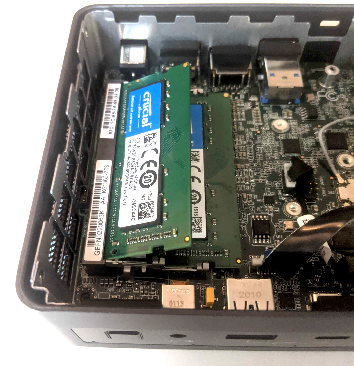
-
To install a RAM stick, slide the stick into the slot at roughly the same angle it was sitting after the latches were released, then push the back edge of the RAM stick downwards so the latches on the sides re-engage.
-
Replace the bottom panel.
Adding/removing a 2.5" storage drive:
If your Meerkat is the tall variety, it has a 2.5" drive bay built into the bottom panel.
Tools required: Cross-head (Phillips) screwdriver
Time estimate: 10 minutes
Difficulty: Easy ●
Steps to add/remove 2.5" storage drives:
- Follow the steps above to remove the bottom panel.
- Take note of the orientation of the connector on the drive you are installing.
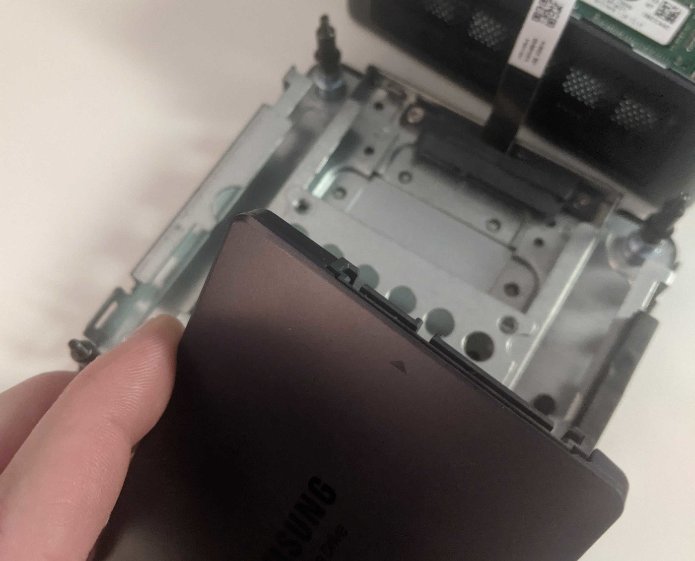
- Slide the drive into the slot on the bottom panel until it plugs all the way into its connector.
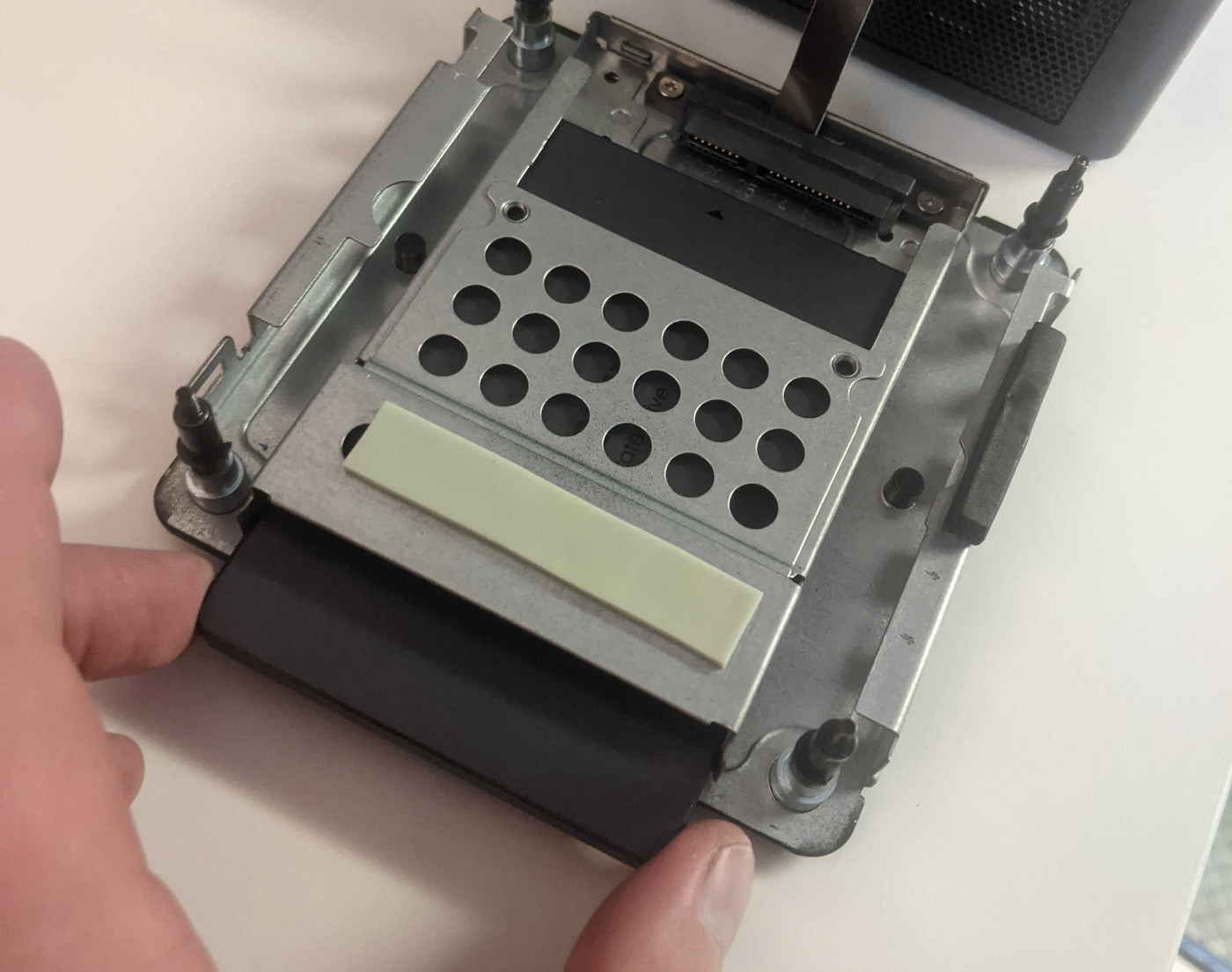
- Replace the bottom panel.
Resetting CMOS:
Sometimes resetting CMOS can help if your Meerkat is not booting. A CMOS reset will restore BIOS settings to their factory defaults, so you may have to reconfigure your BIOS afterwards.
Warning (ingestion hazard): Keep batteries out of reach of children. Death or serious injury can occur if ingested. If a battery is suspected to be swallowed or inserted inside any part of the body, seek immediate medical attention. In the US, you can also call the National Battery Ingestion Hotline for guidance: 1 (800) 498-8666
Tools required: Cross-head (Phillips) screwdriver and (optionally) tweezers
Time estimate: 15 minutes
Difficulty: Medium ●
Steps to reset CMOS:
- Follow the steps above to remove the bottom panel and remove the M.2 drive.
- Disconnect the CMOS battery connector, shown circled in red below. Tweezers may make this easier, but try to pull it by the plug itself rather than by the wires.
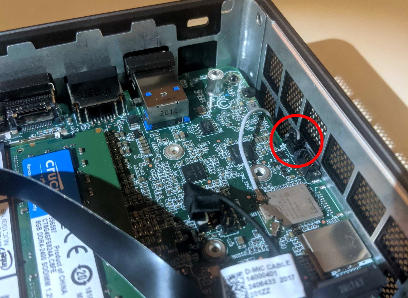
- Leave the connector unplugged for several minutes. CMOS values don't always clear instantly, and sometimes it takes a couple minutes for them to reset.
- Reconnect the CMOS battery.
- Replace the M.2 drive and the bottom panel.
- When you boot your Meerkat after resetting CMOS, it may take a minute or two longer than usual to boot the first time. It has to re-initialize some of the CMOS values that were reset.
Removing the Motherboard:
Removing the motherboard is necessary for removing the cooling fan, cleaning the CPU heatsink, and replacing the CPU thermal paste.
Tools required: Cross-head (Phillips) screwdriver
Time estimate: 20 minutes
Difficulty: High ●
Steps to remove the motherboard:
- Follow the steps above to remove the bottom panel, remove the M.2 drive, and remove the RAM.
- If your Meerkat is the tall variety, disconnect the ribbon cable that leads to the 2.5" drive bay built into the bottom panel. The small white latch comes up to unlock the cable, then the cable can be gently pulled free from its socket.
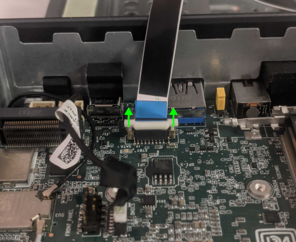
- Disconnect the front microphone cable.
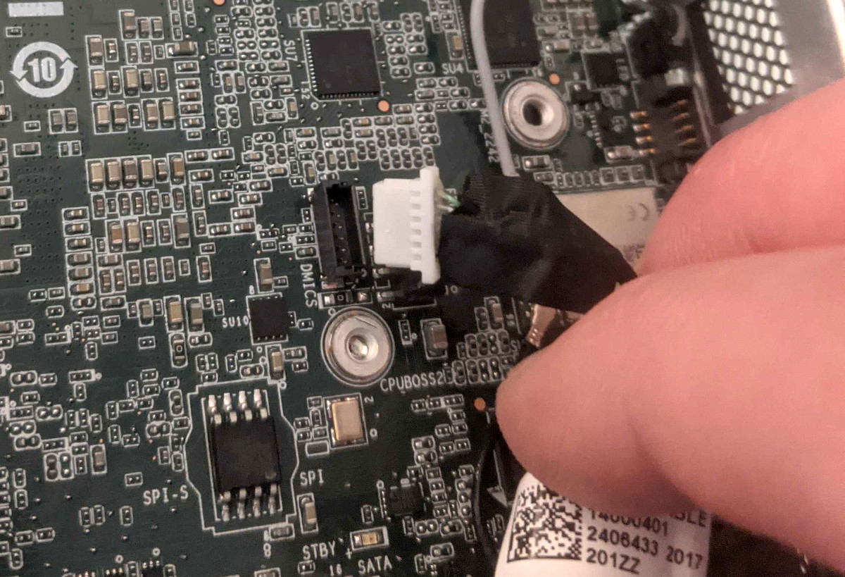
- Disconnect the two wireless antenna cables.
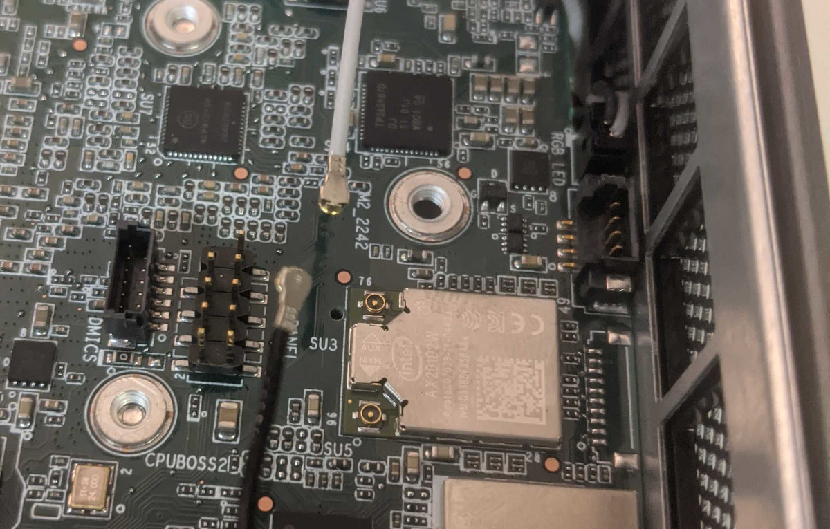
- Remove the two motherboard mounting screws.
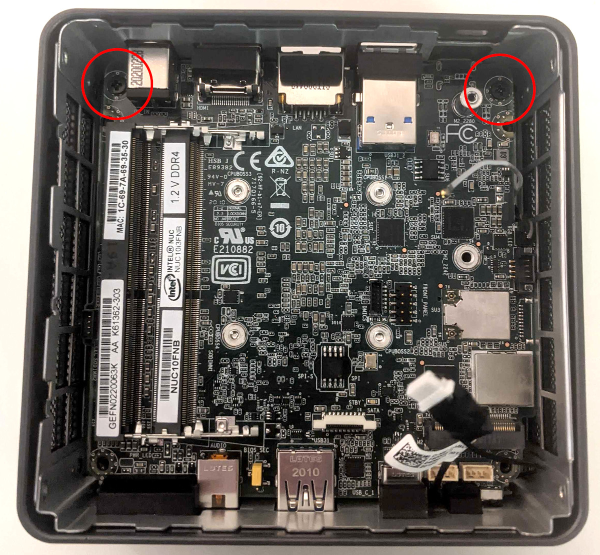
- Carefully lift the motherboard out of the case. It is easiest to lift from the back side, grabbing the USB type A ports as shown below. The back wall of the case can be pulled slightly outwards, away from the motherboard, to help the ports come out of their cutouts in the case.
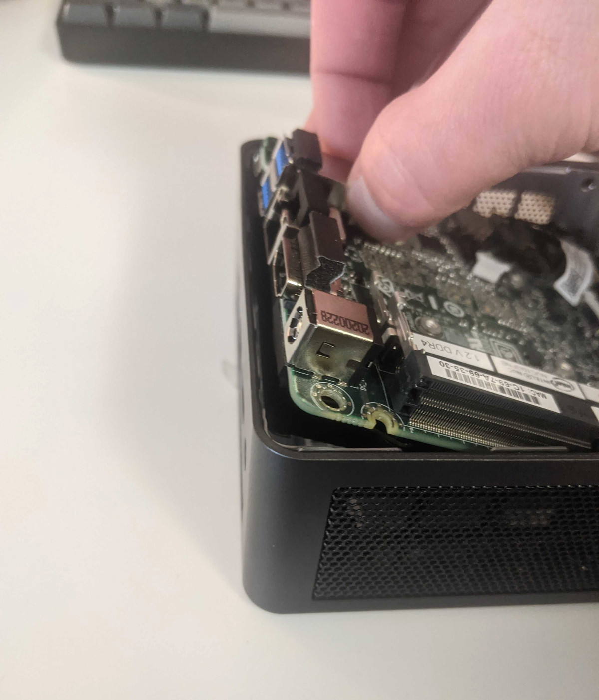
Removing the Fan:
The cooling fan can be removed to clean dust out of the cooling system or to access the CPU heatsink to replace the CPU thermal paste.
Tools required: Cross-head (Phillips) screwdriver
Time estimate: 25 minutes
Difficulty: High ●
Steps to remove the fan:
-
Follow the steps above to remove the motherboard.
-
Completely loosen the three mounting screws (highlighted in red) and disconnect the fan cable (highlighted in green). The screws are captive, so they will not come out of the fan assembly when they are completely loosened.
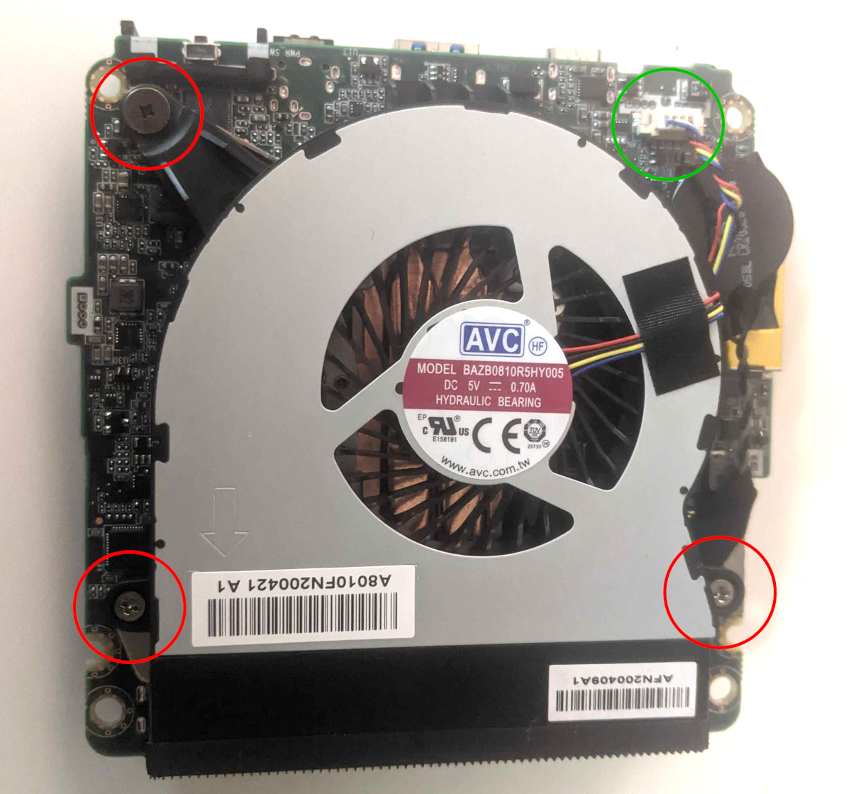
- The fan can now be lifted away from the motherboard.
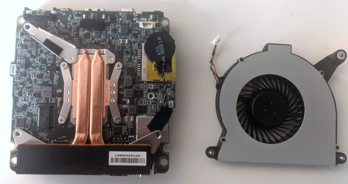
Replacing Thermal Paste:
The CPU cooler dissipates heat from the CPU to the heatsink, where the CPU fan expels it from the system. Depending on your climate and the age of the machine, replacing the thermal paste between the CPU and the heatsink may help the system run cooler.
Tools required: Cross-head (Phillips) screwdriver
Time estimate: 35 minutes
Difficulty: High ●
Steps to replace the thermal paste:
-
Follow the steps above to remove the fan.
-
Completely loosen the four screws that hold the heatsink onto the motherboard (highlighted in red). The screws are captive, so they will not come out of the heatsink brackets when completely loosened.

- Gently lift the heatsink off of the motherboard.

- Using a paper towel, clean the old thermal paste off of the heatsink and CPU. You may also use a small amount of rubbing alcohol if the old paste is dried or difficult to remove.
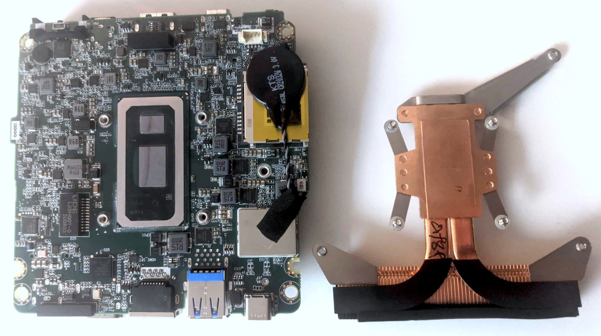
- Apply new thermal paste to both silicon dies on the CPU. Be careful not to use too much, as just a little goes a long way.
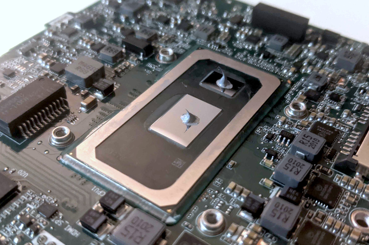
- Reinstall the heatsink and tighten the four screws in the order indicated by the numbers stamped on the heatsink (highlighted in red).
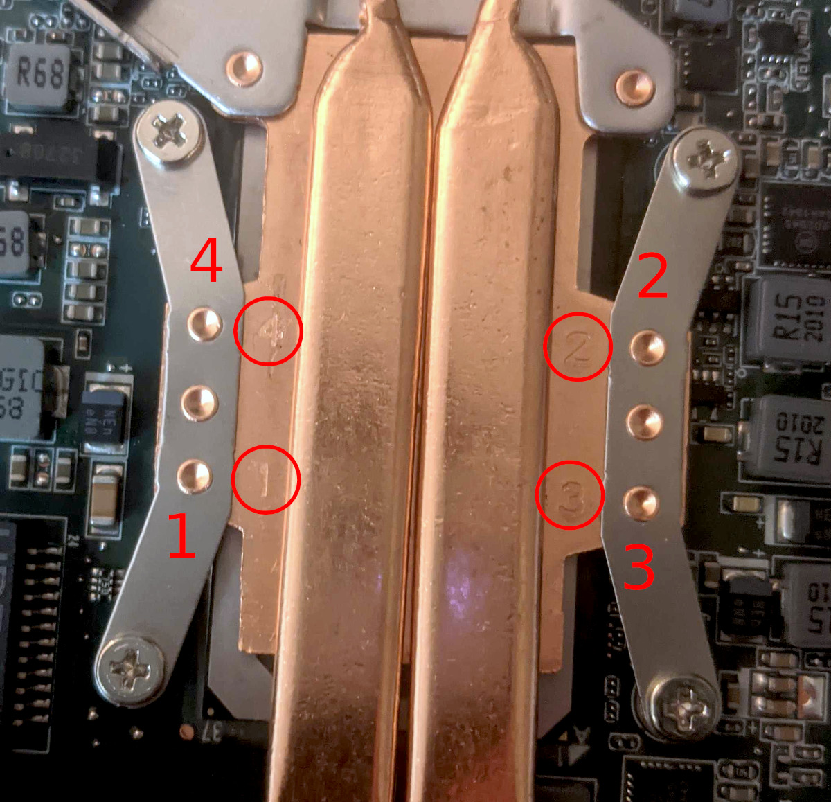
- Reinstall the cooling fan (remember to plug it in!), motherboard, RAM, drive, and bottom panel.
Mounting with VESA Mount:
Your Meerkat comes with a VESA mount adapter, which allows it to be mounted on the back of a monitor. Because it mounts to the monitor's VESA mount, this will only work on monitors which aren't already mounted via the VESA mount.
Tools required: Cross-head (Phillips) screwdriver
Time estimate: 10 minutes
Difficulty: Easy ●
Steps to mount with the VESA adapter:
- Thread the two shoulder screws into the two screw holes in the bottom of the Meerkat.
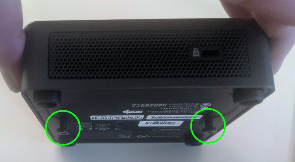
- Mount the VESA adapter plate to the VESA mount on your monitor with the remaining four screws. The "UP" arrow indicates the orientation it should be mounted in.
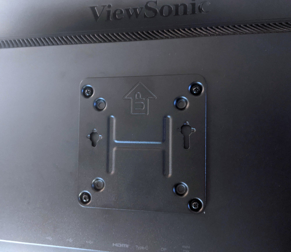
- Align the two shoulder screw studs to the cutouts in the VESA adapter. Once the studs are lined up, slide the Meerkat downwards and rotate it slightly clockwise to lock it into place.
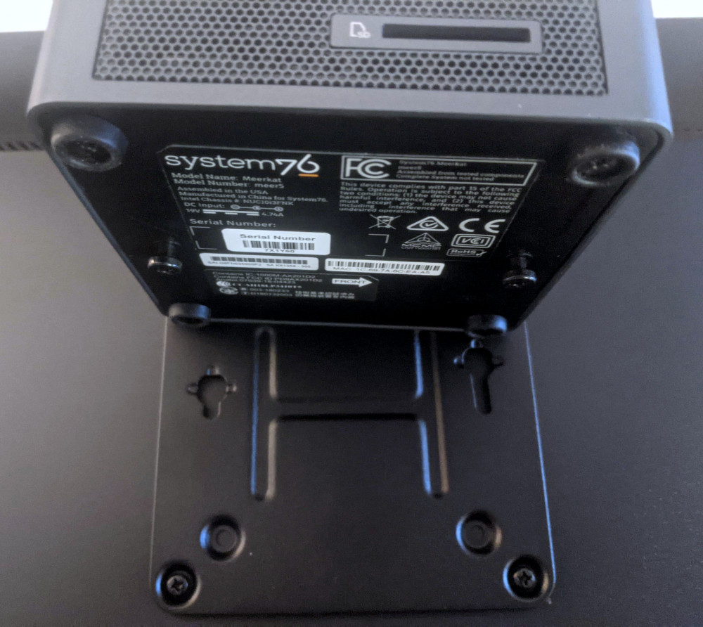
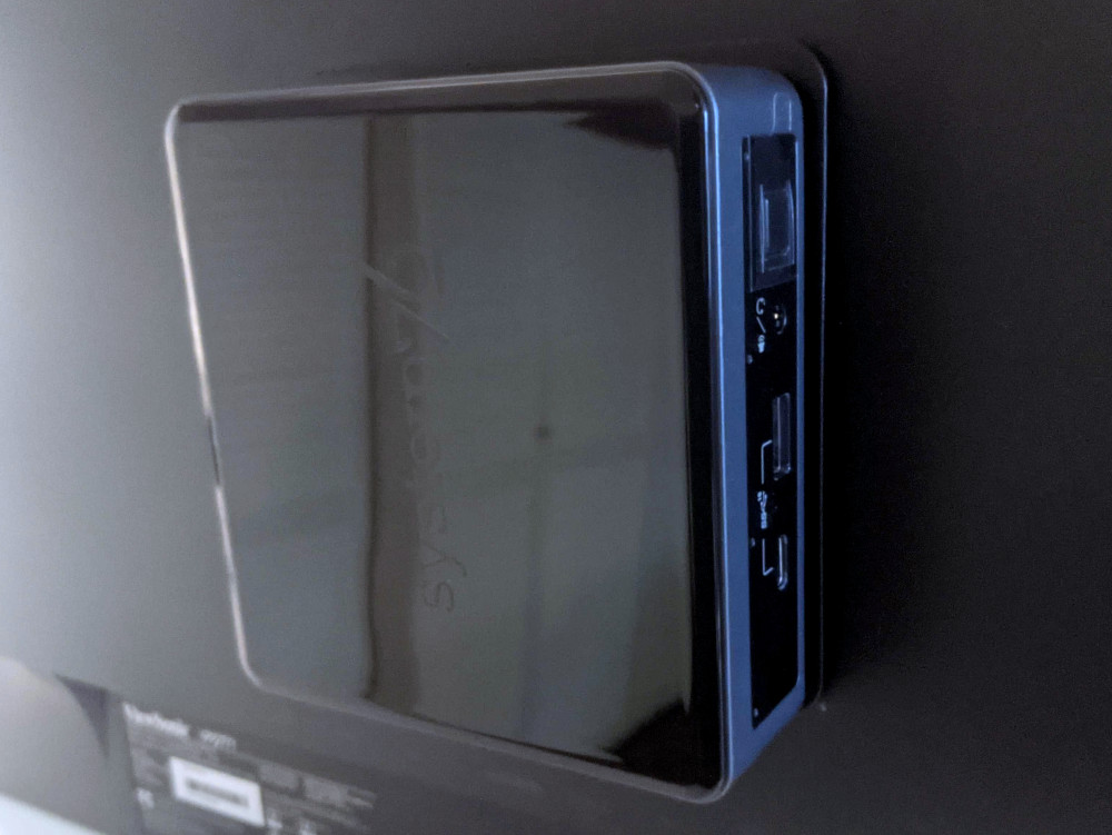
nebula36 (nebula36-1)
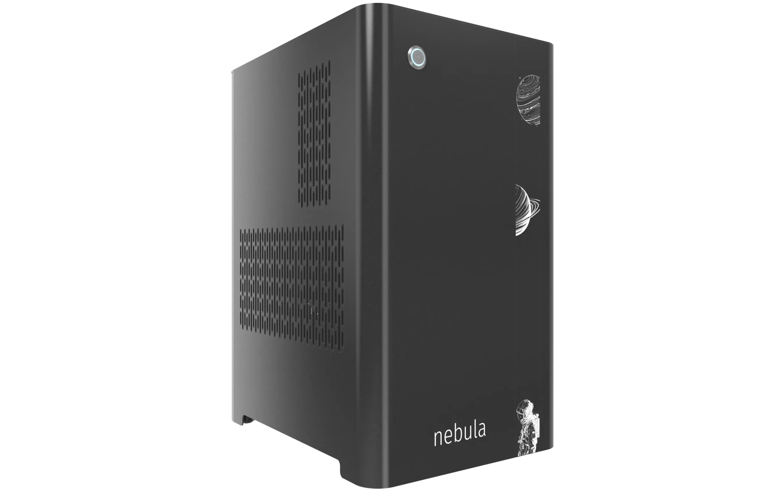
The System76 nebula36 is a desktop chassis (for DIY builds) with the following specifications:
- Dimensions
- Size: 43.6cm × 25.3cm × 31.9cm
- Volume: 36 liters
- Motherboard sizes
- ATX
- Mini-DTX
- DTX
- MicroATX
- Mini-ITX
- GPU compatibility
- Internal clearance: 318.80mm
- Recommended maximum length: 308.80mm
- Cooling capacity
- 2x 120mm CPU fans
- Rear exhaust fan: Be Quiet!
SIW4-12025-MF-PWM - CPU cooler (optional add-on): Noctua
NH-U12S- Fan included with add-on: Noctua
NF-F12 PWM
- Fan included with add-on: Noctua
- Rear exhaust fan: Be Quiet!
- 1x 140mm bottom intake fan: Be Quiet!
SIW4-14025-LF-PWM - 2x 120mm side intake fans
- Optional add-on: Be Quiet!
SIW4-12025-MF-PWM
- Optional add-on: Be Quiet!
- 2x 120mm CPU fans
- Daughterboards
- Nebula Io power button controller board
- MYS7523 Rev. 2.0 front I/O board
- Thelio Io SATA 2.5" drive backplane (optional add-on)
nebula36 (External Overview)
Front/back overview:

Left/right side overview:

Top/bottom overview:

nebula36 (Parts & Assembly)
The nebula36 chassis is ready to be outfitted with standard personal computer components. If the system has already been built, ensure the system is powered off and all cables are unplugged from the motherboard, PCIe cards, power supply, and front I/O before opening the chassis.
The preinstalled velcro strips are left partially unwrapped to aid in removal. When building the system, you can optionally wrap the velcro up the rest of the way.
- Replacing the front accent strip
- Removing the top case
- Removing the side fan bracket
- Removing the CPU duct
- Unpacking the included accessories
- Installing the motherboard
- Installing the CPU duct fans
- Installing the GPU
- Installing the SATA backplane
- Installing 2.5" drives
- Replacing the bottom case fan
- Installing side intake fans
- Installing the power supply
- Wiring the front I/O and power button
Replacing the front accent strip:
nebula36 includes a customizable accent panel on the front of the case, which can be swapped to change the case's look and feel. The instructions for swapping the accent are also available in video form.
- Tools required: None
Steps to replace the front accent strip:
- Place the nebula36 on the edge of the desk so the front side is hanging off of the desk.
- The nebula36 can alternatively be lifted or tilted so the front of the computer is hovering above the desk.
- Slide the accent strip down to unlock it.
- The accent can be gripped at the bottom edge.
- Pull the accent strip off of the case, starting with the bottom edge.
- Place the new accent strip onto the front of the case and slide it up to lock it into place.

Removing the top case:
The top case can be removed to access the internal components.
- Tools required: Cross-head (Phillips) screwdriver (optional)
Steps to remove the top case:
- Remove the four outer screws holding the top case onto the machine.

- Slide the top case up and off of the machine.
Removing the side fan bracket:
The side fan bracket provides a mounting point to help keep installed GPUs (or other PCI Express cards) in place while transporting the system. It can also be used to mount up to two extra intake fans (one, a BQ SIW4-12025-MF-PWM, is optional when purchasing the chassis; a second is not included.)

The fan splitter on the side fan bracket is intended for fans mounted on the side fan bracket, and should not be used for the CPU duct fans or the bottom intake fan.
- Tools required: Cross-head (Phillips) screwdriver
Steps to remove the side fan bracket:
- Follow the steps above to remove the top case.
- Unscrew the four screws holding the side fan bracket in place (two on the front of the case, two on the back.)

- Pull the side fan bracket out of the chassis.
Removing the CPU duct:
The CPU duct supports one or more of the CPU fans and guides airflow from the side of the case through the CPU radiator to the back exhaust vent. The CPU duct is custom-designed to work with the Noctua NH-U12S CPU cooler, which is available as an optional add-on at the time of purchase.

- Tools required: Cross-head (Phillips) screwdriver
Steps to remove the CPU duct:
- Follow the steps above to remove the top case.
- Unscrew the two side screws holding the CPU duct onto the top crossbar.

- Unscrew the four back screws holding the CPU duct onto the chassis.
- Hold onto the duct while removing the final screw so it doesn't fall.

- Pull the CPU duct out of the chassis.
- When replacing the CPU duct, ensure all fan cables are plugged into one of the fan splitter boards in the top right of the chassis.
Unpacking the included accessories:
nebula36 includes the following components preinstalled:
- 1x
nebula_iopower button controller board - 1x
MYS7523top I/O board - 3x four-pin fan splitter boards
- 1x back CPU duct fan
- Be Quiet! Silent Wings 4 120mm (
BQ SIW4-12025-MF-PWM)
- Be Quiet! Silent Wings 4 120mm (
- 1x bottom case fan
- Be Quiet! Silent Wings 4 140mm (
BQ SIW4-14025-LF-PWM)
- Be Quiet! Silent Wings 4 140mm (
- 7x short velcro straps
- 1x on the front of the chassis
- 3x on the side of the chassis
- 1x on the bottom of the chassis
- 1x on the CPU duct
- 1x on the side fan bracket
In addition, nebula36 ships with the following non-installed accessories:
- 1x Screw and velcro box
- 15x short velcro straps
- 1x long velcro strap
- 9x motherboard standoffs
- 9x M3 (motherboard) screws
- 4x fan screws
- 1x CPU cooler w/ fan (optional)
- Noctua
NH-U12Sw/NF-F12 PWMfan
- Noctua
- 1x Side bracket fan (optional)
- Be Quiet! Silent Wings 4 120mm (
BQ SIW4-12025-MF-PWM)
- Be Quiet! Silent Wings 4 120mm (
Steps to unpack the included accessories:
- Follow the steps above to remove the top case, remove the side fan bracket, and remove the CPU duct.
- Cut the zip ties holding the accessory boxes in place.
- The image below highlights where the zip ties are joined; they can be cut anywhere, but must be cut between a joint and the chassis in order to be removed.

- Remove the accessory boxes from the chassis.
Installing the motherboard:
nebula36 supports the following standard motherboard sizes:
- ATX
- Mini-DTX
- DTX
- MicroATX
- Mini-ITX
Nine standoffs and motherboard screws are included.
- Tools required: Cross-head (Phillips) screwdriver
Steps to install the motherboard:
- If they are installed, remove the top case, remove the CPU duct and remove the side fan bracket.
- Locate the standoffs and M3 screws from the brown screw and velcro box.

-
Insert the standoffs into the appropriate holes for your motherboard size. The standoff screw holes are marked with shapes on the chassis, which correspond to the most common motherboard sizes:
- Mini-ITX and Mini-DTX: hexagon (4 standoffs)
- MicroATX: square (9 standoffs)
- ATX: triangle (9 standoffs)
The photo below also includes symbols for one additional motherboard size:
- DTX: star (6 standoffs)

- Install the motherboard's I/O shield onto the back of the chassis by pressing it into place from the inside.
- Place the motherboard into the chassis, aligning the motherboard's screw holes with the installed standoffs.
- Screw the motherboard into the standoffs using the M3 screws.
Installing the CPU duct fans:
nebula36 ships with one 120mm fan (BQ SIW4-12025-MF-PWM) installed in the back of the CPU duct. If you install a CPU cooler with its own fan, such as the optional Noctua NH-U12S cooler sold with nebula36 (which includes a Noctua NF-F12 PWM fan), then the CPU cooler's fan can be mounted in the front of the CPU duct.
These instructions use the Noctua NH-U12S as an example.
- Tools required: Cross-head (Phillips) screwdriver
Steps to install the CPU cooler fan (front):

- Remove the
NH-U12Sfrom the box.

- Remove the included
NF-F12fan from the cooler heatsink by pulling the metal tabs (highlighted green above) off of the heatsink and fan. - Install the cooler onto the motherboard/processor.
- Remove the front fan bracket from the CPU duct by unscrewing the four screws (highlighted green below) and pulling it out of the CPU duct.

- Place the spinning side of the fan down and the stationary cover up, then orient the fan so the wire points towards the bottom right.
- Place the fan bracket over the fan so the thinnest side (without the 90-degree flange) is on the left.
- Screw in the four fan screws.
- It may take some force to thread the fan screws into the fan's plastic frame.

- Place the CPU duct fan and bracket into the CPU duct, with the thinnest side of the bracket (without the 90-degree flange) pointed into the duct.
- The spinning side of the fan should face the front of the chassis, while the stationary cover should face the back of the chassis.
- Replace the screws holding the fan bracket onto the CPU duct.
- By default, the bracket is screwed as far back in the chassis (as farthest away from the L-shaped bend in the duct) as possible.
Steps to replace the preinstalled CPU duct fan (back):
- Remove the top case and the CPU duct.
- Remove the back fan bracket from the CPU duct by unscrewing the four screws (highlighted yellow below) and pulling it out of the CPU duct.

- Unscrew the four fan screws holding the fan onto the bracket.

- When reinstalling the fan, the stationary cover should face the back of the chassis, and the wire should face the upper interior corner of the CPU duct. The thinnest side of the bracket (without the 90-degree flange) should face directly into the duct.
- The wire can be run along the top of the fan until it meets the velcro strap.
Installing the GPU:
nebula36 supports GPUs up to 318.80mm long. For optimal cooling and ease of installation, GPUs longer than 308.80mm are not recommended.
These instructions also apply to other PCI Express cards, such as add-in sound cards or networking cards.
- Tools required: Cross-head (Phillips) screwdriver
Steps to install the GPU:
- If not already installed, install the motherboard.
- If the motherboard is already installed and the system is assembled, then remove the top case and remove the side fan bracket.
- Unscrew the two screws holding the PCIe bracket onto the chassis, then remove the bracket.

- Remove a PCIe slot cover for each slot the new GPU will take up.
- Additional slot covers may fall off after removing the PCIe brakcet; hold them up when replacing the bracket.
- Install the GPU into the motherboard.
- Replace the PCIe bracket, which will hold the end of the GPU in place.
Installing the SATA backplane:
nebula36 is designed to work with an optional SATA backplane to allow for easy hot-swapping of 2.5" storage drives. The SATA backplane can be seen below.

- Tools required: Cross-head (Phillips) screwdriver
Steps to install the SATA backplane:
- Remove the top case.
- Unscrew and remove the 2.5" drive cage's cover.

- Unscrew and remove the 2.5" drive cage.

- If the SATA backplane's screw holes are covered by a translucent film, remove the film.
- Place the SATA backplane into the drive cage.
- The backplane should be oriented so the power plug will be at the top of the board after installing the drive cage back into the chassis.
- Screw the backplane into the drive cage from the outside.

- Screw the drive cage back onto the chassis.
- Connect the
POWER0header on the back of the SATA backplane to the power supply, and theDATA0andDATA1ports to two of the motherboard's SATA ports.- The
POWER0header uses a four-pin Berg connector, also known as a floppy drive power connector.
- The

- Install any 2.5" SATA drives and replace the drive cage cover, side fan bracket (if necessary), and top case.
Installing 2.5" drives:
The drive cage can hold two 2.5" drives. Drives of 7.5mm, 9mm, or 15mm are supported. Airflow will decrease below recommended levels with drives larger than 15mm.
- Tools required: Cross-head (Phillips) screwdriver
Steps to install 2.5" drives:
- Remove the top case.
- Unscrew and remove the 2.5" drive cage's cover.

- Remove the plastic ring from the top crossbar and slide out four screws for each drive being installed.

- Insert two screws into each side of the 2.5" drive, then slide the drive into the drive cage, aligning the rubber mounts on the screws around the metal of the drive cage.
- The larger portion of the SATA connector (the power section) should be at the top, while the smaller portion (the data section) should be at the bottom.
- If the optional SATA backplane is not present, connect the SATA data and power cables from the back of the drive cage.
- A cutout in the chassis allows easy access to the back of the drive cage.
Replacing the bottom case fan:
The 140mm bottom case fan (BQ SIW4-14025-LF-PWM) is preinstalled, but can be replaced if it becomes defective. The fan can also be removed to clean its dust filter.
- Tools required: Cross-head (Phillips) screwdriver
Steps to replace the bottom case fan:
- Remove the top case.
- The side fan bracket can optionally be removed to make working with the fan easier.
- If the system is already assembled, unplug the fan from the fan splitter board or motherboard.
- Set the machine down on its side and unscrew the four fan screws.

- When reinstalling the fan, place the dust filter between the fan and the chassis with the shiny side facing the chassis.
Installing side intake fans:
nebula36 supports up to two 120mm side intake fans mounted to the side fan bracket. One 120mm fan (BQ SIW4-12025-MF-PWM) is sold as an optional add-on at the time of purchase.
Steps to install the side intake fans:
- Remove the top case.
- Unpack the fan and rubber mounting pins from the fan box.
- The plastic rings included with the rubber mounting pins are not needed.

- Place the fan in the center of the side fan bracket.
- The spinning side of the fan should face outward, while the stationary label should face inward.
- The preinstalled pinholes on the fan will line up with the long holes in the side fan bracket.
- From the back (inside of the machine), insert the rubber mounting pins through the pinholes at each corner of the fan.
- The side fan bracket can optionally be removed to make working with the rubber mounting pins easier.

- Plug the side fan into one of the headers on the side fan bracket's fan splitter board. The nearby velcro strap can be used to hold the fan's cable.
Installing the power supply:
The system supports standard ATX power supplies. nebula36 includes a dust filter installed over the power supply's fan vent.
- Tools required: Cross-head (Phillips) screwdriver
Steps to install the power supply:
- Remove the top case.
- The side fan bracket can optionally be removed to make working with the power supply easier.
- Place the power supply into the chassis with the fan facing down.
- While holding the power supply against the back of the chassis, screw in the four power supply screws.
- Power supply screws are typically included with the power supply, and are not included with nebula36.

Steps to replace the power supply dust filter:
- Remove the top case and remove the power supply.
- Unscrew the four screws holding the dust filter onto the chassis.

- Remove, clean, and replace the dust filter.
Wiring the front I/O and power button:
nebula36 comes standard with two front daughterboards:
- The
nebula-io_2.2power button controller. - The
MYS7523 Rev. 2.0front I/O board.
The Nebula Io board can be used to power the system on when the top case is removed.
Both daughterboards can be removed and replaced if necessary. The external power button attached to the top case can also be replaced.
- Tools required: Cross-head (Phillips) screwdriver
Steps to wire the front I/O and power button:
- Remove the top case.
- Refer to the below diagram for powering the machine on or removing and replacing either daughterboard:
- The front I/O board screws are highlighted in green.
- The power button controller board screws are highlighted in red.
- The internal power button is highlighted in cyan.

- Refer to the below diagram for wiring the front I/O and power button (the CPU duct and top crossbar have been removed for easier visibility):
- The USB Type-C port cable (highlighted green) connects to the motherboard's USB 3.1 header.
- The audio cable (highlighted yellow) connects to the motherboard's analog audio header.
- The USB Type-A port cable (highlighted cyan) connects to the motherboard's USB 3.0 header.
- The Nebula Io
PMB1header (highlighted red) connects to the motherboard's power button header. - The Nebula Io
PFP1header (highlighted pink) connects to the power button receptacle. - The power button receptacle header (highlighted orange) connects to the Nebula Io board.

Steps to replace the power button:
- Remove the top case.
- Follow the instructions in the Replace the Thelio Power Button support article.
Oryx Pro (oryp12)
The System76 Oryx Pro is a laptop with the following specifications:
- CPU
- Supports Intel 14th Generation (Raptor Lake) CPUs
- Chipset
- BIOS
- GigaDevice GD25B256EYIGR flash chip
- WSON-8 form factor
- Programmed with System76 Open Firmware
- GigaDevice GD25B256EYIGR flash chip
- EC
- ITE IT5570E
- Programmed with System76 EC
- Graphics
- Dedicated GPU options:
- NVIDIA GeForce RTX 4070
- TGP: 115W (140W boost)
- NVIDIA GeForce RTX 4060
- TGP: 115W (140W boost)
- NVIDIA GeForce RTX 4050
- TGP: 115W (140W boost)
- NVIDIA GeForce RTX 4070
- Integrated GPU:
- Intel Iris Xe Graphics
- eDP display options:
- 16" 1920x1200@165Hz LCD
- LCD panel: BOE NV160WUM-NX2 (or equivalent)
- Brightness: 500 nits (cd/m²)
- sRGB color coverage: 100%
- LCD panel: BOE NV160WUM-NX2 (or equivalent)
- 16" 1920x1200@165Hz LCD
- External video output:
- 1x HDMI 2.1
- 1x Mini DisplayPort 1.4
- 1x DisplayPort 1.4 over USB-C
- Dedicated GPU options:
- Memory
- Up to 96GB (2x48GB) dual-channel DDR5 SO-DIMMs @ 5600 MHz
- Networking
- 2.5-Gigabit Ethernet
- M.2 PCIe/CNVi WiFi/Bluetooth options:
- Intel Wi-Fi 7 BE200
- Bluetooth 5.4
- Intel Wi-Fi 6E AX210/AX211
- Bluetooth 5.3
- Intel Wi-Fi 7 BE200
- Power
- 230W (20.0V, 11.5A) DC-in port
- Barrel size: 5.5mm (outer), 2.5mm (inner)
- Included AC adapter: Lite-On PA-1231-26
- AC power cord type: IEC C5
- 73Wh 4-cell battery
- Model number: NV40BAT-4-73
- 230W (20.0V, 11.5A) DC-in port
- Sound
- Internal speakers & microphone
- Combined headphone & microphone 3.5mm jack
- Combined microphone & S/PDIF (optical) 3.5mm jack
- HDMI, Mini DisplayPort, USB-C DisplayPort audio
- Storage
- 2x M.2 (PCIe NVMe Gen 4)
- MicroSD card reader
- USB
- 1x USB Type-C with Thunderbolt 4
- Supports DisplayPort over USB-C
- Does not support USB-C charging (USB-PD)
- 1x USB 3.2 Gen 2 Type-C
- 2x USB 3.2 Gen 1 Type-A
- 1x USB Type-C with Thunderbolt 4
- Dimensions
- 35.95cm x 27.3cm x 1.99cm, 2.7kg
Oryx Pro (External Overview)
Left side:

Right side:

Front side:

Back side:

Keyboard & touchpad:

Lid:

Materials:
| Part | Material | Part Number |
|---|---|---|
| LCD back cover (lid) | Aluminum | 6-39-PE601-023-1 |
| LCD front cover (bezel) | Plastic | 6-39-PE601-013 |
| Top case (palm rests/port covers) | Plastic | 6-78-PE6S2-012 |
| Bottom panel | Aluminum | 6-39-PE603-014-1 |
LED indicators:
| Icon | Color | Description |
|---|---|---|
 | Orange | Powered off, DC power plugged in |
| Green | Powered on | |
| Blinking green | Sleeping (suspended) | |
 | Orange | Battery charging |
| Green | Battery fully charged | |
| Blinking orange | Battery critically low | |
 | Green | Storage drive activity |
Keyboard shortcuts:
| Key | Shortcut | Action |
|---|---|---|
 | Fn+F1 | Toggle trackpad |
 | Fn+F2 | Toggle microphone mute |
 | Fn+F3 | Mute |
 | Fn+F5 | Volume down |
 | Fn+F6 | Volume up |
 | Fn+F7 | Toggle displays |
 | Fn+F8 | Screen brightness down |
 | Fn+F9 | Screen brightness up |
 | Fn+F10 | Toggle webcam |
 | Fn+F11 | Toggle airplane mode |
 | Fn+F12 | Suspend |
 | Fn+` | Play/Pause |
 | Fn+* | Toggle keyboard backlight |
 | Fn+/ | Cycle keyboard color |
 | Fn+- | Decrease keyboard brightness |
 | Fn++ | Increase keyboard brightness |
| 1 | Fn+1 | Toggle fan between max/automatic |
Oryx Pro (Internal Overview)
Bottom components and connectors:

- Webcam/microphone connector is highlighted in yellow
- Webcam/microphone connector is underneath the heatsink
- LCD panel connector is highlighted in orange
- LCD panel connector is underneath the heatsink
- Fan connectors are highlighted in cyan
- RAM is highlighted in dark green
- BIOS flash chip (U63) is highlighted in black
- Touchpad connector is highlighted in white
- Wireless card is highlighted in purple
- Speaker connectors are highlighted in light green
- Battery connector is highlighted in red
- M.2 SSDs are highlighted in maroon
- Both slots support PCIe NVMe Gen 4
- CMOS battery connector is highlighted in pink
- CMOS battery is underneath SSD slot 2 (closest to the main battery)
Under-keyboard components and connectors:

- Left I/O ribbon is highlighted in red
- Keyboard connector is highlighted in yellow
- Keyboard backlight connector is highlighted in cyan
- Power button/LED connector is highlighted in green
Oryx Pro (Parts & Repairs)
Many components in your Oryx Pro can be upgraded or replaced as necessary.
- Removing the bottom cover
- Replacing the RAM
- Replacing an M.2/NVMe SSD
- Replacing the WiFi/Bluetooth module
- Replacing the battery
- Replacing the CMOS battery
- Replacing the fans/heatsink/thermal paste
- Replacing the speakers
- Replacing the keyboard
Removing the bottom cover:
Removing the cover is required to access the internal components. Prior to removing the cover, ensure the AC power is unplugged and all peripherals (including SD cards and USB drives) are unplugged or removed from the system.
Part numbers:
- Bottom panel:
6-39-PE603-014-1
Tools required: Cross-head (Phillips) screwdriver
Time estimate: 5 minutes
Difficulty: Easy ●
Steps to remove the bottom cover:
- Place the machine lid-side down.
- Use a soft surface (such as a towel) to avoid scratches.
- Remove the 16 bottom panel screws.

- Pull the bottom panel off, starting from the hinges in the back.
Replacing the RAM:
The Oryx Pro 12 supports up to 96GB (2x48GB) of DDR5 SO-DIMMs running at 5600MHz. If you've purchased new RAM, need to replace your RAM, or are reseating your RAM, follow these steps.
Tools required: Cross-head (Phillips) screwdriver
Time estimate: 10 minutes
Difficulty: Easy ●
Steps to replace the RAM:
- Follow the steps above to remove the bottom cover.
- Press the small tabs on both sides of the RAM simultaneously. The RAM should spring up to an angle.

- Remove the RAM from the slot.
- Insert the new RAM (or reseat the existing RAM) by placing it in the keyed slot and pressing down on the RAM until it clicks into place.
Replacing an M.2/NVMe SSD:
This model supports up to two M.2 SSDs. Both M.2 slots are size 2280. Both slots support PCIe NVMe Generation 4 only. The slots are backwards-compatible with PCIe NVMe Generation 3 drives, but the slots do not support SATA.
Tools required: Cross-head (Phillips) screwdriver
Time estimate: 10 minutes
Difficulty: Easy ●
Steps to replace the M.2 drive:
- Follow the steps above to remove the bottom cover.
- Unscrew the retainer screw opposite the M.2 slot.

- Remove the existing M.2 drive by pulling it out of the slot.
- Insert the new M.2 drive into the slot and hold it in place.
- Replace the retainer screw.
- If you are using a slot for the first time, you can optionally remove the plastic backing from the thermal strip and apply it to the inner side of the bottom panel.

Replacing the battery:
The battery provides primary power whenever the system is unplugged.
Part numbers:
- The battery's model number is
NV40BAT-4-73, and the original part number is6-87-NV4RS-71M00.- Third-party battery sellers may list one or both of these numbers, and may offer other compatible part numbers with the same model number.
- You can also contact System76 to purchase a replacement battery.
Tools required: Cross-head (Phillips) screwdriver
Time estimate: 10 minutes
Difficulty: Easy ●
Steps to replace the battery:
- Follow the steps above to remove the bottom cover.
- Remove the five silver battery screws along the perimeter of the battery.

- Unplug the white connector (highlighted yellow above) connecting the battery to the motherboard.
- Remove the battery, starting from the bottom edge with screw holes.
- When putting in the new battery, start with the plastic tabs along the top edge (opposite from the screw holes.)
- When plugging in the new battery, the red wire on the connector goes on the left, and the black wire goes on the right.
Replacing the wireless card:
Your Oryx Pro's WiFi and Bluetooth are both handled by the same module. It is a standard M.2 2230 slot with PCIe and USB interfaces (E-key).
Part numbers:
- The standard wireless card is an Intel
AX211NGW.
Tools required: Cross-head (Phillips) screwdriver
Time estimate: 10 minutes
Difficulty: Medium ●
Steps to replace the WiFi/Bluetooth module:
- Follow the steps above to remove the bottom cover.
- Locate the wireless card. Remove any clear tape that is securing the wires.

- Gently remove the two antennas (highlighted red above) by pulling them up and away from the wireless card.
- Remove the retaining screw opposite the M.2 slot, highlighted yellow above.
- Keeping the wireless card parallel with the motherboard, slide the card out of the M.2 slot.
- Insert the new wireless card into the M.2 slot.
- Replace the retaining screw.
- Attach the two antennas by aligning the circular fittings and pressing onto the wireless card. The connectors will snap into place. Use caution when attaching the connectors; the pins can bend, break, or snap.
Replacing the CMOS battery:
The CMOS battery supplies power to the system's CMOS chip. UEFI settings and the computer's hardware clock are stored on the CMOS. If your system doesn't boot, you can reset the CMOS to force a low-level hardware reset. If your clock is constantly resetting, it's likely your CMOS battery needs to be replaced.
Warning (ingestion hazard): Keep batteries out of reach of children. Death or serious injury can occur if ingested. If a battery is suspected to be swallowed or inserted inside any part of the body, seek immediate medical attention. In the US, you can also call the National Battery Ingestion Hotline for guidance: 1 (800) 498-8666
Part numbers:
- The CMOS battery is a standard 3V KTS CR2032W battery.
Tools required: Cross-head (Phillips) screwdriver
Time estimate: 15 minutes
Difficulty: Medium ●
Steps to replace the CMOS battery:
- Follow the steps above to remove the bottom cover and, if installed, remove the SSD from slot 2 (closest to the main battery).

- Unplug the small white connector that connects the CMOS battery to the motherboard. If you are replacing the battery, gently pull from the sides to pry it up from where it's stuck to the case.
- To clear the CMOS, disconnect the main battery (if it's still installed), open the lid of the machine, and hold down the power button for at least 15 seconds to discharge any residual energy in the system.
- Reconnect the CMOS battery, reconnect the main battery, and replace the M.2 SSD in slot 2 (if necessary).
- Replace the bottom panel and power up the Oryx Pro. The system may power itself off and on after initial boot; this is normal behavior when the CMOS has been reset.
Replacing the cooling system:
The Oryx Pro 12 uses two fans and a heatsink manufactured as a single assembly.
If the fans become noisy and cleaning them out doesn't fix the issue, you may need a new fan. Contact support to start a warranty claim or parts purchase. These instructions can also be used if physical damage to the heatsink necessitates its replacement.
Thermal paste helps facilitate effective heat transfer between the CPU/GPU and the cooling equipment; depending on your climate and the age of the machine, replacing the thermal paste may improve cooling performance. The thermal paste should generally be replaced whenever the heatsink is removed.
Thermal putty (thicker than thermal paste) is used to bridge the gap between the VRAM chips and the heatsink. Replacing the thermal putty is optional when removing the heatsink. System76 suggests Thermal Grizzly Putty Basic (available at various retailers) or a similar alternative.
Part numbers:
- Heatsink/fan assembly: YINGFAN
6-31-PE6SN-102 - Individual fans (may not be available separately):
- Left fan: WINMA
ECG-82090S2-0AH - Right fan: WINMA
ECG-85090S1-0AH
- Left fan: WINMA
Tools required: Cross-head (Phillips) screwdriver, thermal putty spreader (flat plastic tool)
Time estimate: 40 minutes
Difficulty: High ●
Steps to replace the fans/heatsink/thermal paste:
- Follow the steps above to remove the bottom cover.
- Remove any clear tape that is securing the fan wires.
- Remove the heatsink and fan screws in the order of the stamped and stickered numbers, starting with #1, then #2, and continuing until you have removed #13.
- The black screws are held captive and will not fully come away from the heatsink. The silver screw (#13) is not held captive.
- Do not remove the smaller black screws holding the fan covers onto the fans.

- Unplug the two fan connectors from the motherboard (highlighted red above).
- Remove the heatsink/fans from the case, being careful not to bend the heatsink pipes. It may take some pressure to break the seal of the thermal paste.
- Using a paper towel, remove the existing thermal paste from the CPU chips and the GPU chip, as well as the corresponding points on the heat sink. You may also use a small amount of rubbing alcohol if the old paste is dried or difficult to remove.
- You can optionally remove the thermal putty from the four Samsung VRAM chips surrounding the GPU chip and the seven
R15chips forming an "L" shape around the CPU if you have replacement thermal putty to install. - Some thermal paste and/or putty may already be on the motherboard around the VRAM chips, or may get onto the motherboard while cleaning the paste/putty off of the chips. Thermal paste and putty is typically not conductive; it's safer to leave excess paste on the board than to risk damaging the board with rough removal.
- You can optionally remove the thermal putty from the four Samsung VRAM chips surrounding the GPU chip and the seven

- Apply a small line of thermal paste directly onto both CPU chips and the GPU chip.
- If you're also replacing the thermal putty, apply the new putty to the four Samsung VRAM chips and the seven
R15chips. - If you aren't replacing the thermal putty, scoop the existing putty (from the chip and the corresponding location on the heatsink) into the center of each VRAM and
R15chip using a flat plastic tool.
- If you're also replacing the thermal putty, apply the new putty to the four Samsung VRAM chips and the seven

- Carefully replace the heatsink.
- Replace the silver heatsink and fan screws, starting with #1, then #2, and so on until #12.
- Plug the two white fan connectors back into the motherboard.
Replacing the speakers:
The system has two bottom-firing speakers, which can be removed and replaced individually.
Part numbers:
- Left speaker:
6-23-5PE60-0L1 - Right speaker:
6-23-5PE60-0R1
Tools required: Cross-head (Phillips) screwdriver
Time estimate: 10 minutes
Difficulty: Easy ●
Steps to replace the speakers:
- Follow the steps above to remove the bottom cover.
- Disconnect the speaker wire from the motherboard.
- This can alternatively be done after freeing the speaker.

- Unscrew the speaker screws and lift the speaker out of the machine.
- The right speaker has three screws; the left speaker has two screws.
- The speaker wire may be partially routed through channels in the chassis; be careful when removing it.
- Place the new speaker in the machine, plug in the connector, replace the screws, and reinstall the bottom panel.
Replacing the keyboard:
The keyboard can be replaced if its switches or electronics have been damaged.
Part numbers:
- Keyboard:
6-PE60SNE-G-KB-MCL-US- Keyboards shipped by System76 include a custom-printed Super key.
Tools required: Cross-head (Phillips) screwdriver
Time estimate: 5 minutes
Difficulty: Easy ●
Steps to replace the keyboard:
- Place the machine lid-side down.
- Use a soft surface (such as a towel) to avoid scratches.
- Remove the two keyboard screws (highlighted yellow below).

- Open the lid slightly and place the machine on its side.
- Push the screwdriver into the keyboard push point (highlighted cyan above) until the keyboard pops out.

- Set the machine back down and raise the keyboard away from the chassis. The larger ribbon cable is for the keyboard, while the smaller ribbon cable is for the keyboard backlight.

- Flip the black latches upwards to free the ribbon cables.
- Pull the ribbon cables out of the connectors.
- Remove the keyboard and replace it with the new one.
- Carefully slide both ribbon cables into their connectors.
- Flip the black latches back into place to secure the ribbon cables.
- Place the keyboard back into position, starting with the tabs on the bottom edge.
- Secure the rest of the keyboard by pressing down on each of its edges.
- Turn the machine lid-side down again and replace the two keyboard screws.
Oryx Pro (oryp11)
The System76 Oryx Pro is a laptop with the following specifications:
- CPU
- Supports Intel 13th Generation (Raptor Lake) CPUs
- Chipset
- BIOS
- GigaDevice GD25B256EYIGR flash chip
- WSON-8 form factor
- Programmed with System76 Open Firmware
- GigaDevice GD25B256EYIGR flash chip
- EC
- ITE IT5570E
- Programmed with System76 EC
- Graphics
- Dedicated GPU options:
- NVIDIA GeForce RTX 4070
- TGP: 115W (140W boost)
- NVIDIA GeForce RTX 4060
- TGP: 115W (140W boost)
- NVIDIA GeForce RTX 4050
- TGP: 115W (140W boost)
- NVIDIA GeForce RTX 4070
- Integrated GPU:
- Intel Iris Xe Graphics
- eDP display options:
- 16" 1920x1200@165Hz LCD
- LCD panel: BOE NV160WUM-NX2 (or equivalent)
- 16" 1920x1200@165Hz LCD
- External video output:
- 1x HDMI 2.1
- 1x Mini DisplayPort 1.4
- 1x DisplayPort 1.4 over USB-C
- Dedicated GPU options:
- Memory
- Up to 96GB (2x48GB) dual-channel DDR5 SO-DIMMs @ 5200 MHz
- Networking
- Gigabit Ethernet
- M.2 PCIe/CNVi WiFi/Bluetooth
- Intel Wi-Fi 6 AX210/AX211
- Power
- RTX 4050 model:
- 180W (20.0V, 9A) DC-in port
- Barrel size: 5.5mm (outer), 2.5mm (inner)
- Included AC adapter: Lite-On PA-1181-76
- AC power cord type: IEC C5
- 180W (20.0V, 9A) DC-in port
- RTX 4060 and 4070 models:
- 230W (20.0V, 11.5A) DC-in port
- Barrel size: 5.5mm (outer), 2.5mm (inner)
- Included AC adapter: Lite-On PA-1231-26
- AC power cord type: IEC C5
- 230W (20.0V, 11.5A) DC-in port
- 73Wh 4-cell battery
- Model number: NV40BAT-4-73
- RTX 4050 model:
- Sound
- Internal speakers & microphone
- Combined headphone & microphone 3.5mm jack
- Combined microphone & S/PDIF (optical) 3.5mm jack
- HDMI, Mini DisplayPort, USB-C DisplayPort audio
- Storage
- 2x M.2 (PCIe NVMe Gen 4)
- MicroSD card reader
- USB
- 1x USB Type-C with Thunderbolt 4
- Supports DisplayPort over USB-C
- Does not support USB-C charging (USB-PD)
- 1x USB 3.2 Gen 2 Type-C
- 2x USB 3.2 Gen 1 Type-A
- 1x USB Type-C with Thunderbolt 4
- Dimensions
- 35.95cm x 27.3cm x 1.99cm, 2.7kg
Oryx Pro (External Overview)
Left side overview:

Right side overview:

Front side overview:

Back side overview:

Keyboard & touchpad overview:

Materials:
| Part | Material | Part Number |
|---|---|---|
| LCD back cover (lid) | Aluminum | 6-39-PE601-022 |
| LCD front cover (bezel) | Plastic | 6-39-PE601-012 |
| Top case (palm rests/port covers) | Plastic | 6-78-PE60RNEG2-010 |
| Bottom panel | Aluminum | 6-39-PE603-012 |
LED indicators:
| Icon | Color | Description |
|---|---|---|
 | Orange | Powered off, DC power plugged in |
| Green | Powered on | |
| Blinking green | Sleeping (suspended) | |
 | Orange | Battery charging |
| Green | Battery fully charged | |
| Blinking orange | Battery critically low | |
 | Green | Storage drive activity |
Keyboard shortcuts:
| Key | Shortcut | Action |
|---|---|---|
 | Fn+F1 | Toggle trackpad |
 | Fn+F2 | Toggle microphone mute |
 | Fn+F3 | Mute |
 | Fn+F5 | Volume down |
 | Fn+F6 | Volume up |
 | Fn+F7 | Toggle displays |
 | Fn+F8 | Screen brightness down |
 | Fn+F9 | Screen brightness up |
 | Fn+F10 | Toggle webcam |
 | Fn+F11 | Toggle airplane mode |
 | Fn+F12 | Suspend |
 | Fn+` | Play/Pause |
 | Fn+* | Toggle keyboard backlight |
 | Fn+/ | Cycle keyboard color |
 | Fn+- | Decrease keyboard brightness |
 | Fn++ | Increase keyboard brightness |
| 1 | Fn+1 | Toggle fan between max/automatic |
Oryx Pro (Internal Overview)
Bottom components and connectors:

- Webcam/microphone connector is highlighted in yellow
- Webcam/microphone connector is underneath the heatsink
- LCD panel connector is highlighted in orange
- LCD panel connector is underneath the heatsink
- Fan connectors are highlighted in cyan
- RAM is highlighted in dark green
- BIOS flash chip (U60) is highlighted in black
- Touchpad connector is highlighted in white
- Wireless card is highlighted in purple
- Speaker connectors are highlighted in light green
- Battery connector is highlighted in red
- M.2 SSDs are highlighted in maroon
- Both slots support PCIe NVMe Gen 4
- CMOS battery connector is highlighted in pink
- CMOS battery is underneath SSD slot 2 (closest to the main battery)
Under-keyboard components and connectors:

- Left I/O ribbon is highlighted in red
- Keyboard connector is highlighted in yellow
- Keyboard backlight connector is highlighted in cyan
- Power button/LED connector is highlighted in green
Oryx Pro (Parts & Repairs)
Many components in your Oryx Pro can be upgraded or replaced as necessary.
- Removing the bottom cover
- Replacing the RAM
- Replacing an M.2/NVMe SSD
- Replacing the WiFi/Bluetooth module
- Replacing the battery
- Replacing the CMOS battery
- Replacing the fans/heatsink/thermal paste
- Replacing the speakers
- Replacing the keyboard
Removing the bottom cover:
Removing the cover is required to access the internal components. Prior to removing the cover, ensure the AC power is unplugged and all peripherals (including SD cards and USB drives) are unplugged or removed from the system.
Tools required: Cross-head (Phillips) screwdriver
Time estimate: 5 minutes
Difficulty: Easy ●
Steps to remove the bottom cover:
- Place the machine lid-side down.
- Use a soft surface (such as a towel) to avoid scratches.
- Remove the 16 bottom panel screws.

- Pull the bottom panel off, starting from the hinges in the back.
Replacing the RAM:
The Oryx Pro 11 supports up to 96GB (2x48GB) of DDR5 SO-DIMMs running at 5200MHz. If you've purchased new RAM, need to replace your RAM, or are reseating your RAM, follow these steps.
Tools required: Cross-head (Phillips) screwdriver
Time estimate: 10 minutes
Difficulty: Easy ●
Steps to replace the RAM:
- Follow the steps above to remove the bottom cover.
- Press the small tabs on both sides of the RAM simultaneously. The RAM should spring up to an angle.

- Remove the RAM from the slot.
- Insert the new RAM (or reseat the existing RAM) by placing it in the keyed slot and pressing down on the RAM until it clicks into place.
Replacing an M.2/NVMe SSD:
This model supports up to two M.2 SSDs. Both M.2 slots are size 2280. Both slots support PCIe NVMe Generation 4 only. The slots are backwards-compatible with PCIe NVMe Generation 3 drives, but the slots do not support SATA.
Tools required: Cross-head (Phillips) screwdriver
Time estimate: 10 minutes
Difficulty: Easy ●
Steps to replace the M.2 drive:
- Follow the steps above to remove the bottom cover.
- Unscrew the retainer screw opposite the M.2 slot.

- Remove the existing M.2 drive by pulling it out of the slot.
- Insert the new M.2 drive into the slot and hold it in place.
- Replace the retainer screw.
- If you are using a slot for the first time, you can optionally remove the plastic backing from the thermal strip and apply it to the inner side of the bottom panel.

Replacing the battery:
The battery provides primary power whenever the system is unplugged.
The model number for the Oryx Pro 11's battery is NV40BAT-4-73, and the original part number is 6-87-NV4RS-71M00. Third-party battery sellers may list one or both of these numbers, and may offer other compatible part numbers with the same model number. You can also contact System76 to purchase a replacement battery.
Tools required: Cross-head (Phillips) screwdriver
Time estimate: 10 minutes
Difficulty: Easy ●
Steps to replace the battery:
- Follow the steps above to remove the bottom cover.
- Remove the five silver battery screws along the perimeter of the battery.

- Unplug the white connector (highlighted yellow above) connecting the battery to the motherboard.
- Remove the battery, starting from the bottom edge with screw holes.
- When putting in the new battery, start with the plastic tabs along the top edge (opposite from the screw holes.)
- When plugging in the new battery, the red wire on the connector goes on the left, and the black wire goes on the right.
Replacing the wireless card:
Your Oryx Pro's WiFi and Bluetooth are both handled by the same module. It is a standard M.2 2230 slot with PCIe and USB interfaces (E-key).
Tools required: Cross-head (Phillips) screwdriver
Time estimate: 10 minutes
Difficulty: Medium ●
Steps to replace the WiFi/Bluetooth module:
- Follow the steps above to remove the bottom cover.
- Locate the wireless card. Remove any clear tape that is securing the wires.

- Gently remove the two antennas (highlighted red above) by pulling them up and away from the wireless card.
- Remove the retaining screw opposite the M.2 slot, highlighted yellow above.
- Keeping the wireless card parallel with the motherboard, slide the card out of the M.2 slot.
- Insert the new wireless card into the M.2 slot.
- Replace the retaining screw.
- Attach the two antennas by aligning the circular fittings and pressing onto the wireless card. The connectors will snap into place. Use caution when attaching the connectors; the pins can bend, break, or snap.
Replacing the CMOS battery:
The CMOS battery supplies power to the system's CMOS chip. UEFI settings and the computer's hardware clock are stored on the CMOS. If your system doesn't boot, you can reset the CMOS to force a low-level hardware reset. If your clock is constantly resetting, it's likely your CMOS battery needs to be replaced.
Warning (ingestion hazard): Keep batteries out of reach of children. Death or serious injury can occur if ingested. If a battery is suspected to be swallowed or inserted inside any part of the body, seek immediate medical attention. In the US, you can also call the National Battery Ingestion Hotline for guidance: 1 (800) 498-8666
Tools required: Cross-head (Phillips) screwdriver
Time estimate: 15 minutes
Difficulty: Medium ●
Steps to replace the CMOS battery:
- Follow the steps above to remove the bottom cover and, if installed, remove the SSD from slot 2 (closest to the main battery).

- Unplug the small white connector that connects the CMOS battery to the motherboard. If you are replacing the battery, gently pull from the sides to pry it up from where it's stuck to the case.
- To clear the CMOS, disconnect the main battery (if it's still installed), open the lid of the machine, and hold down the power button for at least 15 seconds to discharge any residual energy in the system.
- Reconnect the CMOS battery, reconnect the main battery, and replace the M.2 SSD in slot 2 (if necessary).
- Replace the bottom panel and power up the Oryx Pro. The system may power itself off and on after initial boot; this is normal behavior when the CMOS has been reset.
Replacing the cooling system:
The Oryx Pro 11 uses two fans and a heatsink manufactured as a single assembly. The part number for the complete assembly is YINGFAN 6-31-PE60N-102. The part number for the left fan is WINMA EFC-92091S2-0BH; the part number for the right fan is WINMA EFC-90091S2-0BH.
If the fans become noisy and cleaning them out doesn't fix the issue, you may need a new fan. Contact support to start a warranty claim or parts purchase. These instructions can also be used if physical damage to the heatsink necessitates its replacement.
Thermal paste helps facilitate effective heat transfer between the CPU/GPU and the cooling equipment; depending on your climate and the age of the machine, replacing the thermal paste may improve cooling performance. The thermal paste should generally be replaced whenever the heatsink is removed.
Thermal putty (thicker than thermal paste) is used to bridge the gap between the VRAM chips and the heatsink. Replacing the thermal putty is optional when removing the heatsink. System76 suggests Thermal Grizzly Putty Basic (available at various retailers) or a similar alternative.
Tools required: Cross-head (Phillips) screwdriver, thermal putty spreader (flat plastic tool)
Time estimate: 40 minutes
Difficulty: High ●
Steps to replace the fans/heatsink/thermal paste:
- Follow the steps above to remove the bottom cover.
- Remove any clear tape that is securing the fan wires.
- Remove the heatsink and fan screws in the order of the stamped and stickered numbers, starting with #1, then #2, and continuing until you have removed #12.
- Note: Do not remove the smaller screws holding the fan covers onto the fans.

- Unplug the two fan connectors from the motherboard (highlighted red above).
- Remove the heatsink/fans from the case, being careful not to bend the heatsink pipes. It may take some pressure to break the seal of the thermal paste.
- Using a paper towel, remove the existing thermal paste from the CPU chips and the GPU chip, as well as the corresponding points on the heat sink. You may also use a small amount of rubbing alcohol if the old paste is dried or difficult to remove.
- You can optionally remove the thermal putty from the three Samsung VRAM chips and the twelve
R15chips surrounding the GPU chip if you have replacement thermal putty to install. - Some thermal paste and/or putty may already be on the motherboard around the VRAM chips, or may get onto the motherboard while cleaning the paste/putty off of the chips. Thermal paste and putty is typically not conductive; it's safer to leave excess paste on the board than to risk damaging the board with rough removal.
- You can optionally remove the thermal putty from the three Samsung VRAM chips and the twelve

- Apply a small line of thermal paste directly onto both CPU chips and the GPU chip.
- If you're also replacing the thermal putty, apply the new putty to the three Samsung VRAM chips and the twelve
R15chips. - If you aren't replacing the thermal putty, scoop the existing putty (from the chip and the corresponding location on the heatsink) into the center of each VRAM and
R15chip using a flat plastic tool.
- If you're also replacing the thermal putty, apply the new putty to the three Samsung VRAM chips and the twelve

- Carefully replace the heatsink.
- Replace the silver heatsink and fan screws, starting with #1, then #2, and so on until #12.
- Plug the two white fan connectors back into the motherboard.
Replacing the speakers:
The system has two bottom-firing speakers, which can be removed and replaced individually.
Tools required: Cross-head (Phillips) screwdriver
Time estimate: 10 minutes
Difficulty: Easy ●
Steps to replace the speakers:
- Follow the steps above to remove the bottom cover.
- Disconnect the speaker wire from the motherboard.
- This can alternatively be done after freeing the speaker.

- Unscrew the speaker screws and lift the speaker out of the machine.
- The right speaker has three screws; the left speaker has two screws.
- The speaker wire may be partially routed through channels in the chassis; be careful when removing it.
- Place the new speaker in the machine, plug in the connector, replace the screws, and reinstall the bottom panel.
Replacing the keyboard:
The keyboard can be replaced if its switches or electronics have been damaged.
Tools required: Cross-head (Phillips) screwdriver
Time estimate: 5 minutes
Difficulty: Easy ●
Steps to replace the keyboard:
- Place the machine lid-side down.
- Use a soft surface (such as a towel) to avoid scratches.
- Remove the two keyboard screws (highlighted yellow below).

- Open the lid slightly and place the machine on its side.
- Push the screwdriver into the keyboard push point (highlighted cyan above) until the keyboard pops out.

- Set the machine back down and raise the keyboard away from the chassis. The larger ribbon cable is for the keyboard, while the smaller ribbon cable is for the keyboard backlight.

- Flip the black latches upwards to free the ribbon cables.
- Pull the ribbon cables out of the connectors.
- Remove the keyboard and replace it with the new one.
- Carefully slide both ribbon cables into their connectors.
- Flip the black latches back into place to secure the ribbon cables.
- Place the keyboard back into position, starting with the tabs on the bottom edge.
- Secure the rest of the keyboard by pressing down on each of its edges.
- Turn the machine lid-side down again and replace the two keyboard screws.
Oryx Pro (oryp10)
The System76 Oryx Pro is a laptop with the following specifications:
- CPU
- Supports Intel Alder Lake CPUs
- Chipset
- BIOS
- Macronix MX25L25673GZ4I-08G flash chip
- WSON-8 form factor
- Programmed with System76 Open Firmware
- Macronix MX25L25673GZ4I-08G flash chip
- EC
- ITE IT5570E
- Programmed with System76 EC
- Graphics
- Dedicated GPU options:
- NVIDIA GeForce RTX 3080 Ti (Max-Q)
- TGP: 80W
- NVIDIA GeForce RTX 3070 Ti (Max-Q)
- TGP: 80W
- NVIDIA GeForce RTX 3080 Ti (Max-Q)
- Integrated GPU:
- Intel Iris Xe Graphics
- eDP display options:
- 15.6" 3840x2160@60Hz OLED
- OLED panel: Samsung ATNA56WR14-0 (or equivalent)
- 15.6" 1920x1080@144Hz LCD
- LCD panel: BOE NV156FHM-NY5 (or equivalent)
- 17.3" 1920x1080@144Hz LCD
- LCD panel: BOE NV173FHM-NY1 (or equivalent)
- 15.6" 3840x2160@60Hz OLED
- External video output:
- 1x HDMI 2.1
- 1x Mini DisplayPort 1.4
- 2x DisplayPort 1.4 over USB-C
- Dedicated GPU options:
- Memory
- Up to 64GB (2x32GB) dual-channel DDR5 SO-DIMMs @ 4800 MHz
- Networking
- Gigabit Ethernet
- M.2 PCIe/CNVi WiFi/Bluetooth
- Intel Wi-Fi 6 AX200/AX201
- Power
- 230W (20.0V, 11.5A) DC-in port
- Barrel size: 5.5mm (outer), 2.5mm (inner)
- Included AC adapter: Lite-On PA-1231-26
- AC power cord type: IEC C5
- 80Wh 6-cell Lithium-Ion battery
- 15" model number: PD50BAT-6-80
- 17" model number: PD70BAT-6-80
- 230W (20.0V, 11.5A) DC-in port
- Sound
- Internal speakers & microphone
- Combined headphone & microphone 3.5mm jack
- Combined microphone & S/PDIF (optical) 3.5mm jack
- HDMI, Mini DisplayPort, USB-C DisplayPort audio
- Storage
- 2x M.2 (PCIe NVMe Gen 4)
- MicroSD card reader
- USB
- 1x USB Type-C with Thunderbolt 4
- Supports DisplayPort over USB-C
- Does not support USB-C charging (USB-PD)
- 1x USB 3.2 Gen 2 Type-C
- Supports DisplayPort over USB-C
- Does not support USB-C charging (USB-PD)
- 2x USB 3.2 Gen 1 Type-A
- 1x USB Type-C with Thunderbolt 4
- Dimensions
- 15": 35.814cm x 24.003cm x 2.489cm, 2.4kg
- 17": 39.599cm x 26.213cm x 2.489cm, 2.8kg
Oryx Pro (External Overview)
Left side overview:

Right side overview:

Front side overview:

Back side overview:

Keyboard & touchpad overview:

Materials:
| Part | Material |
|---|---|
| LCD back cover (lid) | Aluminum |
| LCD front cover (bezel) | Plastic |
| Top case (palm rests/port covers) | Plastic |
| Bottom panel | Aluminum |
LED indicators:
| Icon | Color | Description |
|---|---|---|
 | Orange | Powered off, DC power plugged in |
| Green | Powered on | |
| Blinking green | Sleeping (suspended) | |
 | Orange | Battery charging |
| Green | Battery fully charged | |
| Blinking orange | Battery critically low | |
 | Green | Storage drive activity |
Keyboard shortcuts:
| Key | Shortcut | Action |
|---|---|---|
 | Fn+F1 | Toggle trackpad |
 | Fn+F2 | Toggle built-in LCD (non-OLED models only) |
 | Fn+F3 | Mute |
 | Fn+F5 | Volume down |
 | Fn+F6 | Volume up |
 | Fn+F7 | Toggle displays |
 | Fn+F8 | Screen brightness down |
 | Fn+F9 | Screen brightness up |
 | Fn+F10 | Toggle webcam |
 | Fn+F11 | Toggle airplane mode |
 | Fn+F12 | Suspend |
 | Fn+` | Play/Pause |
 | Fn+* | Toggle keyboard backlight |
| / | Fn+/ | Cycle keyboard color |
| - | Fn+- | Decrease keyboard brightness |
| + | Fn++ | Increase keyboard brightness |
| 1 | Fn+1 | Toggle fan between max/automatic |
Oryx Pro (Internal Overview)
Bottom components and connectors:

- Fan connectors are highlighted in cyan
- Webcam/microphone connector is highlighted in yellow
- M.2 SSDs are highlighted in maroon
- Wireless card is highlighted in purple
- Wireless card is underneath the innermost SSD
- CMOS battery connector is highlighted in blue
- CMOS battery connector is underneath the outermost SSD
- Speaker connectors are highlighted in light green
- Right speaker connector is underneath the outermost SSD
- Touchpad connector is highlighted in white
- Battery connector is highlighted in red
- RAM is highlighted in dark green
- BIOS flash chip (U60) is highlighted in black
- LCD panel connector is highlighted in orange
- Keyboard adhesive access hole is highlighted in pink
Under-keyboard components and connectors:

- Keyboard connector is highlighted in yellow
- Keyboard backlight connector is highlighted in cyan
- Keyboard adhesive strip (used) is highlighted in red
- Access hole is located on the left side
- Power button/LED connector is highlighted in green
Oryx Pro (Parts & Repairs)
Many components in your Oryx Pro can be upgraded or replaced as necessary. This page uses photos of the 15" model, but screw counts, general component locations, and other details are the same on the 17" model unless otherwise noted.
- Removing the bottom cover
- Replacing the RAM
- Replacing an M.2/NVMe SSD
- Replacing the WiFi/Bluetooth module
- Replacing the battery
- Replacing the CMOS battery
- Replacing the fans/heatsink/thermal paste
- Replacing the speakers
- Replacing the keyboard
Removing the bottom cover:
Removing the cover is required to access the internal components. Prior to removing the cover, ensure the AC power is unplugged and all peripherals (including SD cards and USB drives) are unplugged or removed from the system.
Tools required: Cross-head (Phillips) screwdriver
Time estimate: 5 minutes
Difficulty: Easy ●
Steps to remove the bottom cover:
- Place the machine lid-side down.
- Use a soft surface (such as a towel) to avoid scratches.
- Remove the 16 bottom panel screws.
- All screws are the same length on any given unit. However, the 17" model uses longer screws than the 15" model.

- Pull the bottom panel off, starting from the hinges in the back.
Replacing the RAM:
The Oryx Pro 10 supports up to 64GB (2x32GB) of DDR5 SO-DIMMs running at 4800MHz. If you've purchased new RAM, need to replace your RAM, or are reseating your RAM, follow these steps.
Tools required: Cross-head (Phillips) screwdriver
Time estimate: 10 minutes
Difficulty: Easy ●
Steps to replace the RAM:
- Follow the steps above to remove the bottom cover.
- Press the small tabs on both sides of the RAM simultaneously. The RAM should spring up to an angle.

- Remove the RAM from the slot.
- Insert the new RAM (or reseat the existing RAM) by placing it in the keyed slot and pressing down on the RAM until it clicks into place.
Replacing an M.2/NVMe SSD:
This model supports up to two M.2 SSDs. Both M.2 slots are size 2280. Both slots support PCIe NVMe Generation 4 only. The slots are backwards-compatible with PCIe NVMe Generation 3 drives, but the slots do not support SATA.
Tools required: Cross-head (Phillips) screwdriver
Time estimate: 10 minutes
Difficulty: Easy ●
Steps to replace the M.2 drive:
- Follow the steps above to remove the bottom cover.
- Unscrew the retainer screw opposite the M.2 slot.

- Remove the existing M.2 drive by pulling it out of the slot.
- Insert the new M.2 drive into the slot and hold it in place.
- Replace the retainer screw.
Replacing the battery:
The battery provides primary power whenever the system is unplugged.
The model and part numbers for the Oryx Pro 10's battery are dependent on the screen size:
- For the 15" model, the battery model is
PD50BAT-6-80and the original part number is6-87-PD50S-82B01. - For the 17" model, the battery model is
PC70BAT-6-80and the original part number is6-87-PD70S-82B01.
Third-party battery sellers may list one or both of these numbers, and may offer other compatible part numbers with the same model number. You can also contact System76 to purchase a replacement battery.
Tools required: Cross-head (Phillips) screwdriver
Time estimate: 10 minutes
Difficulty: Easy ●
Steps to replace the battery:
- Follow the steps above to remove the bottom cover.
- Remove the two silver battery screws along the bottom of the battery.

- Unplug the white connector (highlighted yellow above) connecting the battery to the motherboard.
- Remove the battery, starting from the bottom edge with screw holes.
- When putting in the new battery, start with the plastic tabs along the top edge (opposite from the screw holes.)
- When plugging in the new battery, the red wire on the connector goes on the left, and the black wire goes on the right.
Replacing the wireless card:
Your Oryx Pro's WiFi and Bluetooth are both handled by the same module. It is a standard M.2 2230 slot with PCIe and USB interfaces (E-key).
Tools required: Cross-head (Phillips) screwdriver
Time estimate: 10 minutes
Difficulty: Medium ●
Steps to replace the WiFi/Bluetooth module:
- Follow the steps above to remove the bottom cover and remove both SSDs.
- Removing the outermost SSD is optional, but will make it easier to work with the wireless card.
- Locate the wireless card. Remove any clear tape that is securing the wires.

- Gently remove the two antennas (highlighted red above) by pulling them up and away from the wireless card.
- Remove the retaining screw opposite the M.2 slot, highlighted yellow above.
- Keeping the wireless card parallel with the motherboard, slide the card out of the M.2 slot.
- Insert the new wireless card into the M.2 slot.
- Replace the retaining screw.
- Attach the two antennas by aligning the circular fittings and pressing onto the wireless card. The connectors will snap into place. Use caution when attaching the connectors; the pins can bend, break, or snap.
Replacing the CMOS battery:
The CMOS battery supplies power to the system's CMOS chip. UEFI settings and the computer's hardware clock are stored on the CMOS. If your system doesn't boot, you can reset the CMOS to force a low-level hardware reset. If your clock is constantly resetting, it's likely your CMOS battery needs to be replaced.
Warning (ingestion hazard): Keep batteries out of reach of children. Death or serious injury can occur if ingested. If a battery is suspected to be swallowed or inserted inside any part of the body, seek immediate medical attention. In the US, you can also call the National Battery Ingestion Hotline for guidance: 1 (800) 498-8666
Tools required: Cross-head (Phillips) screwdriver
Time estimate: 15 minutes
Difficulty: Medium ●
Steps to replace the CMOS battery:
- Follow the steps above to remove the bottom cover, remove both SSDs, and remove the wireless card.
- If you are not replacing the CMOS battery, then removing the wireless card is optional.\

- Unplug the small white connector that connects the CMOS battery to the motherboard. If you are replacing the battery, gently pull from the sides to pry it up from where it's stuck to the case.
- To clear the CMOS, disconnect the main battery (if it's still installed), open the lid of the machine, and hold down the power button for at least 15 seconds to discharge any residual energy in the system.
- Reconnect the CMOS battery, reconnect the main battery, and replace the M.2 SSD.
- Replace the bottom panel and power up the Oryx Pro. The system may power itself off and on after initial boot; this is normal behavior when the CMOS has been reset.
Replacing the cooling system:
If the CPU/GPU fans become noisy and cleaning them out doesn't fix the issue, you may need a new fan.
The Oryx Pro 10 comes with heat-conductive metal on the dedicated GPU, and uses regular thermal paste for the CPU. These materials help facilitate effective heat transfer between the CPU/GPU and the cooling equipment.
- Thermal paste should generally be replaced after removing the heatsink; thermal paste also dries over time, so depending on your climate and the age of the machine, applying new thermal paste may increase thermal performance.
- The heat-conductive metal does not dry out, and replacing it is optional; replacement may be useful if the previous metal has flowed out of the proper area for cooling.
Replacement heat-conductive metal fitted to the machine and replacement fans can be obtained by contacting support.
Tools required: Cross-head (Phillips) screwdriver
Time estimate: 40 minutes
Difficulty: High ●
Steps to replace the fans/heatsink/thermal paste:
- Power off the machine. Wait 20 minutes for the machine to cool down to room temperature.
- Warning: Removing the heatsink before the machine has cooled to room temperature may result in heat-conductive metal flowing onto the motherboard and causing irrepairable damage.
- Follow the steps above to remove the bottom cover.
- Unscrew the fan and heatsink screws in the order of the stamped numbers, starting with #1, then #2, and continuing until you have removed #12.
- The screws are held captive and will not come out of the fans/heatsink. The fan screws will click when they are fully loosened.
- The order for the 17" model is shown below; the screws are numbered differently on the 15" model. Follow the order stamped into the heatsink metal.
- Do not remove the smaller screws holding the fan covers onto the fans.

- If there is any clear tape securing the heatsink/fans or the fan wires, remove it.
- Unplug the two white fan connectors from the motherboard (highlighted red above).
- Remove the heatsink/fans from the case, being careful not to bend the heatsink pipes. It may take some pressure to break the seal of the thermal paste.
- Using a paper towel, remove the existing thermal paste from the CPU, the CPU heatsink, the border of the GPU die, and the GPU heatsink.
- A small amount of rubbing alcohol can be used if the old paste is dried or difficult to remove.
- The heat-conductive metal may have some holes where pieces stuck to the die or heatsink.
- If you are not replacing the heat-conductive metal, do not pick or wipe the heat-conductive metal off of the GPU heatsink.

- If you are replacing the heat-conductive metal, remove the plastic cover from the GPU heatsink.
- A fingernail or a thin plastic tool can be used to pick a side of the plastic cover up from the GPU heatsink.
- Warning: The heat-conductive metal is electrically conductive. Be careful not to get specks of heat-conductive metal onto the motherboard. The heat-conductive metal can cause the motherboard to malfunction or fail if it makes contact.
- After removing the plastic covers, wipe away any remaining heat-conductive metal residue from the heatsink and GPU.
- Some adhesive residue may remain on the GPU heatsink.
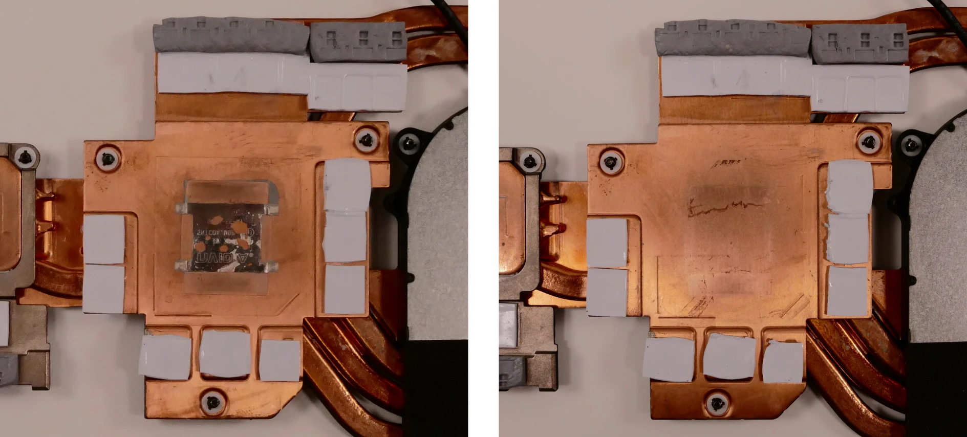
- Apply the new heat-conductive metal to the GPU heatsink, matching the orientation of the plastic covering with the diagonal corner of its respective surface.
- Warning: Replacement heat-conductive metal obtained from System76 will include the plastic covering. If you are applying third-party heat-conductive or liquid metal, clean and reuse the plastic covering from the stock heat-conductive metal to prevent the aftermarket metal from flowing onto the motherboard when heated.
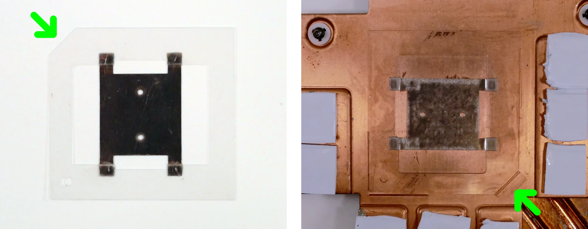
- Apply a small line of thermal paste directly onto each CPU die.
- Apply a line of thermal paste around the border of the GPU die.
- The purpose of this border is to further prevent melted heat-conductive metal from flowing onto the motherboard during operation.
- Keep the nozzle of the thermal paste tube pressed against the surface of the chip; dispense the thermal paste slowly while moving the nozzle.
- Be careful not to apply too much thermal paste around the GPU. Only a thin layer is needed.

- Carefully replace the heatsink.
- Tighten the fan and heatsink screws, starting with #1, then #2, and so on until #12.
- Plug the two white fan connectors back into the motherboard.
Replacing the speakers:
The system has two bottom-firing speakers, which can be removed and replaced individually.
Tools required: Cross-head (Phillips) screwdriver
Time estimate: 10 minutes
Difficulty: Easy ●
Steps to replace the speakers:
- Follow the steps above to remove the bottom cover. For the right speaker, also remove the outermost SSD.
- Disconnect the speaker wire from the motherboard.
- This can alternatively be done after freeing the speaker.

- Unscrew the speaker screws and lift the speaker out of the machine.
- The right speaker has three screws; the left speaker has two screws.
- The speaker wire may be partially routed behind other components or tape; be careful when removing it.
- Place the new speaker in the machine, plug in the connector, replace the screws, and reinstall the outermost SSD (if necessary) and bottom panel.
Replacing the keyboard:
The keyboard can be replaced if its switches or electronics have been damaged.
Warning: The Oryx Pro 10's keyboard is held in by a strip of adhesive in addition to one of the bottom panel screws and the perimeter clips. The adhesive may be difficult to remove from the keyboard and/or case, and while the keyboard should still be functional if removed carefully, it is likely that permanent aesthetic damage will occur to the bottom side of the keyboard during removal. Removal is not recommended unless the keyboard is malfunctioning.
Tools required: Cross-head (Phillips) screwdriver, tweezers, spudger tool (optional)
Time estimate: 20 minutes
Difficulty: Hard ●
Steps to replace the keyboard:
- Follow the steps above to remove the bottom cover.
- Locate the keyboard adhesive strip access point near the right fan.
- You can optionally remove the fan/heatsink assembly to make access easier, but this is not recommended unless you are also removing the thermal paste.
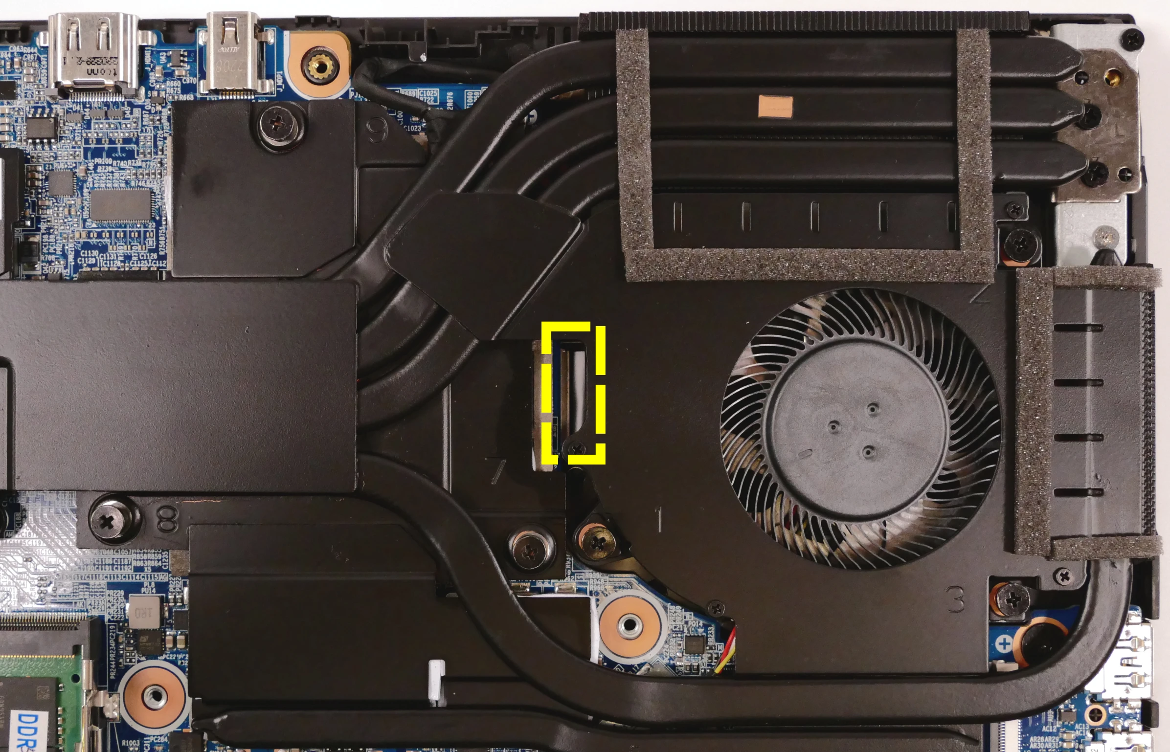
- Using a pair of tweezers, pull out the end of the adhesive strip.

- Open the lid slightly and place the machine on its side.
- Push a screwdriver into the adhesive slot until the keyboard pops out.
- If available, a flathead spudger tool can also be used to provide more contact with the keyboard.
- A layer of plastic may stick to the adhesive and come off of the keyboard. Try to keep as much of the plastic shielding on the keyboard as possible.

- Set the machine back down and raise the keyboard away from the chassis. The larger ribbon cable is for the keyboard, while the smaller ribbon cable is for the keyboard backlight.

- Flip the black latches upwards to free the ribbon cables.
- Pull the ribbon cables out of the connectors.
- Remove the keyboard and replace it with the new one.
- Carefully slide both ribbon cables into their connectors.
- Flip the black latches back into place to secure the ribbon cables.
- Place the keyboard back into position, starting with the tabs on the bottom edge.
- The keyboard is primarily held in place by the perimeter clips and the keyboard screw (one of the bottom panel screws). The adhesive strip can optionally be removed or omitted to make future keyboard removal easier.
- Secure the rest of the keyboard by pressing down on each of its edges.
- Turn the machine lid-side down again and press the adhesive strip back into its slot.
Oryx Pro (oryp9)
The System76 Oryx Pro is a laptop with the following specifications:
- CPU
- Supports Intel Alder Lake CPUs
- Chipset
- BIOS
- Macronix MX25L25673GZ4I-08G flash chip
- WSON-8 form factor
- Programmed with System76 Open Firmware
- Macronix MX25L25673GZ4I-08G flash chip
- EC
- ITE IT5570E
- Programmed with System76 EC
- Graphics
- Dedicated GPU options:
- NVIDIA GeForce RTX 3080 Ti (Max-Q)
- TGP: 80W
- NVIDIA GeForce RTX 3070 Ti (Max-Q)
- TGP: 80W
- NVIDIA GeForce RTX 3080 Ti (Max-Q)
- Integrated GPU:
- Intel Iris Xe Graphics
- eDP display options:
- 15.6" 1920x1080@144Hz LCD
- LCD panel: BOE NV156FHM-NY5 (or equivalent)
- 17.3" 1920x1080@144Hz LCD
- LCD panel: BOE NV173FHM-NY1 (or equivalent)
- 15.6" 1920x1080@144Hz LCD
- External video output:
- 1x HDMI 2.1
- 1x Mini DisplayPort 1.4
- 1x DisplayPort 1.4 over USB-C
- Dedicated GPU options:
- Memory
- Up to 64GB (2x32GB) dual-channel DDR4 SO-DIMMs @ 3200 MHz
- Networking
- Gigabit Ethernet
- M.2 PCIe/CNVi WiFi/Bluetooth
- Intel Wi-Fi 6 AX200/AX201
- Power
- 230W (20.0V, 11.5A) DC-in port
- Barrel size: 5.5mm (outer), 2.5mm (inner)
- Included AC adapter: Lite-On PA-1231-26
- AC power cord type: IEC C5
- 80Wh 6-cell Lithium-Ion battery
- 15" model number: PD50BAT-6-80
- 17" model number: PD70BAT-6-80
- 230W (20.0V, 11.5A) DC-in port
- Sound
- Internal speakers & microphone
- Combined headphone & microphone 3.5mm jack
- Combined microphone & S/PDIF (optical) 3.5mm jack
- HDMI, Mini DisplayPort, USB-C DisplayPort audio
- Storage
- 2x M.2 (PCIe NVMe Gen 4)
- MicroSD card reader
- USB
- 1x USB Type-C with Thunderbolt 4
- Supports DisplayPort over USB-C
- Does not support USB-C charging (USB-PD)
- 1x USB 3.2 Gen 2 Type-C
- 2x USB 3.2 Gen 1 Type-A
- 1x USB Type-C with Thunderbolt 4
- Dimensions
- 15": 35.814cm x 24.003cm x 2.489cm, 1.99kg
- 17": 39.599cm x 26.213cm x 2.489cm, 2.3kg
Oryx Pro (External Overview)
Left side overview:

Right side overview:

Front side overview:

Back side overview:

Materials:
| Part | Material |
|---|---|
| LCD back cover (lid) | Aluminum |
| LCD front cover (bezel) | Plastic |
| Top case (palm rests/port covers) | Plastic |
| Bottom panel | Aluminum |
LED indicators:
| Icon | Color | Description |
|---|---|---|
 | Orange | Powered off, DC power plugged in |
| Green | Powered on | |
| Blinking green | Sleeping (suspended) | |
 | Orange | Battery charging |
| Green | Battery fully charged | |
| Blinking orange | Battery critically low | |
 | Green | Storage drive activity |
Keyboard shortcuts:
| Key | Shortcut | Action |
|---|---|---|
 | Fn+F1 | Toggle trackpad |
 | Fn+F2 | Toggle built-in LCD |
 | Fn+F3 | Mute |
 | Fn+F5 | Volume down |
 | Fn+F6 | Volume up |
 | Fn+F7 | Toggle displays |
 | Fn+F8 | Screen brightness down |
 | Fn+F9 | Screen brightness up |
 | Fn+F10 | Toggle webcam |
 | Fn+F11 | Toggle airplane mode |
 | Fn+F12 | Suspend |
 | Fn+` | Play/Pause |
 | Fn+* | Toggle keyboard backlight |
| / | Fn+/ | Cycle keyboard color |
| - | Fn+- | Decrease keyboard brightness |
| + | Fn++ | Increase keyboard brightness |
| 1 | Fn+1 | Toggle fan between max/automatic |
Oryx Pro (Internal Overview)
Bottom components and connectors:

- Fan connectors are highlighted in cyan
- Webcam/microphone connector is highlighted in yellow
- M.2 SSDs are highlighted in maroon
- Wireless card is highlighted in purple
- Wireless card is underneath the innermost SSD
- CMOS battery connector is highlighted in blue
- CMOS battery connector is underneath the outermost SSD
- Speaker connectors are highlighted in light green
- Right speaker connector is underneath the outermost SSD
- Touchpad connector is highlighted in white
- Battery connector is highlighted in red
- RAM is highlighted in dark green
- BIOS flash chip (U60) is highlighted in black
- LCD panel connector is highlighted in orange
- Keyboard adhesive access hole is highlighted in pink
Under-keyboard components and connectors:

- Keyboard connector is highlighted in yellow
- Keyboard backlight connector is highlighted in cyan
- Keyboard adhesive access hole is highlighted in red
- Power button/LED connector is highlighted in green
Oryx Pro (Parts & Repairs)
Many components in your Oryx Pro can be upgraded or replaced as necessary. This page uses photos of the 17" model, but screw counts, general component locations, and other details are the same on the 15" model unless otherwise noted.
- Removing the bottom cover
- Replacing the RAM
- Replacing an M.2/NVMe SSD
- Replacing the WiFi/Bluetooth module
- Replacing the battery
- Replacing the CMOS battery
- Replacing the fans/heatsink/thermal paste
- Replacing the speakers
- Replacing the keyboard
Removing the bottom cover:
Removing the cover is required to access the internal components. Prior to removing the cover, ensure the AC power is unplugged and all peripherals (including SD cards and USB drives) are unplugged or removed from the system.
Tools required: Cross-head (Phillips) screwdriver
Time estimate: 5 minutes
Difficulty: Easy ●
Steps to remove the bottom cover:
- Place the machine lid-side down.
- Use a soft surface (such as a towel) to avoid scratches.
- Remove the 16 bottom panel screws.

- Pull the bottom panel off, starting from the hinges in the back.
Replacing the RAM:
The Oryx Pro 9 supports up to 64GB (2x32GB) of DDR4 SO-DIMMs running at 3200MHz. If you've purchased new RAM, need to replace your RAM, or are reseating your RAM, follow these steps.
Tools required: Cross-head (Phillips) screwdriver
Time estimate: 10 minutes
Difficulty: Easy ●
Steps to replace the RAM:
- Follow the steps above to remove the bottom cover.
- Press the small tabs on both sides of the RAM simultaneously. The RAM should spring up to an angle.

- Remove the RAM from the slot.
- Insert the new RAM (or reseat the existing RAM) by placing it in the keyed slot and pressing down on the RAM until it clicks into place.
Replacing an M.2/NVMe SSD:
This model supports up to two M.2 SSDs. Both M.2 slots are size 2280. Both slots support PCIe NVMe Generation 4 only. The slots are backwards-compatible with PCIe NVMe Generation 3 drives, but the slots do not support SATA.
Tools required: Cross-head (Phillips) screwdriver
Time estimate: 10 minutes
Difficulty: Easy ●
Steps to replace the M.2 drive:
- Follow the steps above to remove the bottom cover.
- Unscrew the retainer screw opposite the M.2 slot.

- Remove the existing M.2 drive by pulling it out of the slot.
- Insert the new M.2 drive into the slot and hold it in place.
- Replace the retainer screw.
Replacing the battery:
The battery provides primary power whenever the system is unplugged.
The model and part numbers for the Oryx Pro 9's battery are dependent on the screen size:
- For the 15" model, the battery model is
PD50BAT-6-80and the original part number is6-87-PD50S-82B01. - For the 17" model, the battery model is
PC70BAT-6-80and the original part number is6-87-PD70S-82B01.
Third-party battery sellers may list one or both of these numbers, and may offer other compatible part numbers with the same model number. You can also contact System76 to purchase a replacement battery.
Tools required: Cross-head (Phillips) screwdriver
Time estimate: 10 minutes
Difficulty: Easy ●
Steps to replace the battery:
- Follow the steps above to remove the bottom cover.
- Remove the three silver battery screws along the top of the battery.

- Unplug the white connector (highlighted yellow above) connecting the battery to the motherboard.
- Remove the battery, starting from the top edge with screw holes.
- When putting in the new battery, start with the plastic tabs along the bottom edge (opposite from the screw holes.)
- When plugging in the new battery, the red wire on the connector goes on the left, and the black wire goes on the right.
Replacing the wireless card:
Your Oryx Pro's WiFi and Bluetooth are both handled by the same module. It is a standard M.2 2230 slot with PCIe and USB interfaces (E-key).
Tools required: Cross-head (Phillips) screwdriver
Time estimate: 10 minutes
Difficulty: Medium ●
Steps to replace the WiFi/Bluetooth module:
- Follow the steps above to remove the bottom cover and remove both SSDs.
- Removing the outermost SSD is optional, but will make it easier to work with the wireless card.
- Locate the wireless card. Remove any clear tape that is securing the wires.

- Gently remove the two antennas (highlighted red above) by pulling them up and away from the wireless card.
- Remove the retaining screw opposite the M.2 slot, highlighted yellow above.
- Keeping the wireless card parallel with the motherboard, slide the card out of the M.2 slot.
- Insert the new wireless card into the M.2 slot.
- Replace the retaining screw.
- Attach the two antennas by aligning the circular fittings and pressing onto the wireless card. The connectors will snap into place. Use caution when attaching the connectors; the pins can bend, break, or snap.
Replacing the CMOS battery:
The CMOS battery supplies power to the system's CMOS chip. UEFI settings and the computer's hardware clock are stored on the CMOS. If your system doesn't boot, you can reset the CMOS to force a low-level hardware reset. If your clock is constantly resetting, it's likely your CMOS battery needs to be replaced.
Warning (ingestion hazard): Keep batteries out of reach of children. Death or serious injury can occur if ingested. If a battery is suspected to be swallowed or inserted inside any part of the body, seek immediate medical attention. In the US, you can also call the National Battery Ingestion Hotline for guidance: 1 (800) 498-8666
Tools required: Cross-head (Phillips) screwdriver
Time estimate: 15 minutes
Difficulty: Medium ●
Steps to replace the CMOS battery:
- Follow the steps above to remove the bottom cover, remove both SSDs, and remove the wireless card.
- If you are not replacing the CMOS battery, then removing the wireless card is optional.\

- Unplug the small white connector that connects the CMOS battery to the motherboard. If you are replacing the battery, gently pull from the sides to pry it up from where it's stuck to the case.
- To clear the CMOS, disconnect the main battery (if it's still installed), open the lid of the machine, and hold down the power button for at least 15 seconds to discharge any residual energy in the system.
- Reconnect the CMOS battery, reconnect the main battery, and replace the M.2 SSD.
- Replace the bottom panel and power up the Oryx Pro. The system may power itself off and on after initial boot; this is normal behavior when the CMOS has been reset.
Replacing the cooling system:
If the CPU/GPU fans become noisy and cleaning them out doesn't fix the issue, you may need a new fan.
The Oryx Pro 9 comes with heat-conductive metal on the dedicated GPU die and the main CPU die, and uses regular thermal paste for the integrated GPU die. These materials help facilitate effective heat transfer between the CPU/GPU and the cooling equipment.
- Thermal paste should generally be replaced after removing the heatsink; thermal paste also dries over time, so depending on your climate and the age of the machine, applying new thermal paste may increase thermal performance.
- The heat-conductive metal does not dry out, and replacing it is optional; replacement may be useful if the previous metal has flowed out of the proper area for cooling.
Replacement heat-conductive metal fitted to the machine and replacement fans can be obtained by contacting support.
Tools required: Cross-head (Phillips) screwdriver
Time estimate: 40 minutes
Difficulty: High ●
Steps to replace the fans/heatsink/thermal paste:
- Power off the machine. Wait 20 minutes for the machine to cool down to room temperature.
- Warning: Removing the heatsink before the machine has cooled to room temperature may result in heat-conductive metal flowing onto the motherboard and causing irrepairable damage.
- Follow the steps above to remove the bottom cover.
- Unscrew the fan and heatsink screws in the order of the stamped numbers, starting with #1, then #2, and continuing until you have removed #12.
- The screws are held captive and will not come out of the fans/heatsink. The fan screws will click when they are fully loosened.
- The order for the 17" model is shown below; the screws are numbered differently on the 15" model. Follow the order stamped into the heatsink metal.
- Do not remove the smaller screws holding the fan covers onto the fans.

- If there is any clear tape securing the heatsink/fans or the fan wires, remove it.
- Unplug the two white fan connectors from the motherboard (highlighted red above).
- Remove the heatsink/fans from the case, being careful not to bend the heatsink pipes. It may take some pressure to break the seal of the thermal paste.
- Using a paper towel, remove the existing thermal paste from the integrated CPU die, the border of the CPU chip, the CPU heatsink, the border of the GPU die, and the GPU heatsink.
- A small amount of rubbing alcohol can be used if the old paste is dried or difficult to remove.
- The heat-conductive metal may have some holes where pieces stuck to the die or heatsink.
- If you are not replacing the heat-conductive metal, do not pick or wipe the heat-conductive metal off of the main CPU die or the GPU heatsink.

- If you are replacing the heat-conductive metal, remove the plastic covers from the GPU heatsink and the CPU chip.
- A fingernail or a thin plastic tool can be used to pick a side of the plastic cover up from the CPU chip/GPU heatsink.
- Warning: The heat-conductive metal is electrically conductive. Be careful not to get specks of heat-conductive metal onto the motherboard. The heat-conductive metal can cause the motherboard to malfunction or fail if it makes contact.
- After removing the plastic covers, wipe away any remaining heat-conductive metal residue from the heatsink, dedicated GPU die, and main CPU die.
- Some adhesive residue may remain on the GPU heatsink and CPU chip.

- Apply the new heat-conductive metal to the CPU chip and the GPU heatsink, matching the orientation of the plastic coverings with the diagonal corners of their respective surfaces.
- Warning: Replacement heat-conductive metal obtained from System76 will include the plastic covering. If you are applying third-party heat-conductive or liquid metal, clean and reuse the plastic covering from the stock heat-conductive metal to prevent the aftermarket metal from flowing onto the motherboard when heated.
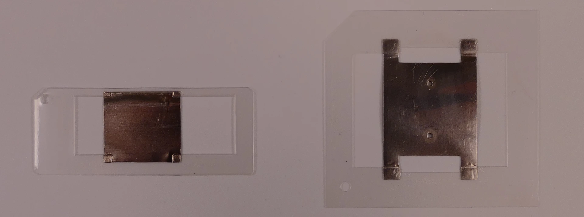
Above: Heat-conductive metal for the CPU (left) and the GPU (right), with plastic coverings.
Below: Heat-conductive metal application on the CPU chip and the GPU heatsink.


- Apply a small line of thermal paste directly onto the integrated GPU die (the smaller die on the CPU chip).

- Apply a line of thermal paste around the border of the CPU chip and the border of the GPU die.
- The purpose of this border is to further prevent melted heat-conductive metal from flowing onto the motherboard during operation.
- Keep the nozzle of the thermal paste tube pressed against the surface of the chip; dispense the thermal paste slowly while moving the nozzle.
- Be careful not to apply too much thermal paste. Only a thin layer is needed.

- Carefully replace the heatsink.
- Tighten the fan and heatsink screws, starting with #1, then #2, and so on until #12.
- Plug the two white fan connectors back into the motherboard.
Replacing the speakers:
The system has two bottom-firing speakers, which can be removed and replaced individually.
Tools required: Cross-head (Phillips) screwdriver
Time estimate: 10 minutes
Difficulty: Easy ●
Steps to replace the speakers:
- Follow the steps above to remove the bottom cover. For the right speaker, also remove the outermost SSD.
- Disconnect the speaker wire from the motherboard.
- This can alternatively be done after freeing the speaker.

- Unscrew the speaker screws and lift the speaker out of the machine.
- The right speaker has three screws; the left speaker has two screws.
- The speaker wire may be partially routed behind other components or tape; be careful when removing it.
- Place the new speaker in the machine, plug in the connector, replace the screws, and reinstall the outermost SSD (if necessary) and bottom panel.
Replacing the keyboard:
The keyboard can be replaced if its switches or electronics have been damaged.
Tools required: Cross-head (Phillips) screwdriver, tweezers
Time estimate: 10 minutes
Difficulty: Medium ●
Steps to replace the keyboard:
- Follow the steps above to remove the bottom cover.
- Locate the keyboard adhesive strip access point near the right fan.

- Using a pair of tweezers, pull out the end of the adhesive strip.

- Open the lid slightly and place the machine on its side.
- Push a screwdriver into the adhesive slot until the keyboard pops out.

- Set the machine back down and raise the keyboard away from the chassis. The larger ribbon cable is for the keyboard, while the smaller ribbon cable is for the keyboard backlight.

- Flip the black latches upwards to free the ribbon cables.
- Pull the ribbon cables out of the connectors.
- Remove the keyboard and replace it with the new one.
- Carefully slide both ribbon cables into their connectors.
- Flip the black latches back into place to secure the ribbon cables.
- Place the keyboard back into position, starting with the tabs on the bottom edge.
- Secure the rest of the keyboard by pressing down on each of its edges.
- Turn the machine lid-side down again and press the adhesive strip back into its slot.
- The keyboard is primarily held in place by the perimeter clips and the keyboard screw (one of the bottom panel screws). The adhesive strip can optionally be removed to make future keyboard removal easier.
Oryx Pro (oryp8)
The System76 Oryx Pro is a laptop with the following specifications:
- CPU
- Supports Intel Tiger Lake CPUs
- Chipset
- BIOS
- GD25B127D flash chip
- SOIC-8 form factor
- Programmed with System76 Open Firmware
- GD25B127D flash chip
- EC
- ITE IT5570E
- Programmed with System76 EC
- Graphics
- Dedicated GPU options:
- NVIDIA GeForce RTX 3080 (Max-Q)
- TGP: 80W
- NVIDIA GeForce RTX 3070 (Max-Q)
- TGP: 80W
- NVIDIA GeForce RTX 3080 (Max-Q)
- Integrated GPU:
- Intel UHD Graphics
- eDP display options:
- 15.6" 1920x1080@144Hz LCD
- LCD panel: LG LP156WFG-SPB3 (or equivalent)
- 17.3" 1920x1080@144Hz LCD
- LCD panel: LG LP173WFG-SPB3 (or equivalent)
- 15.6" 1920x1080@144Hz LCD
- External video output:
- 1x HDMI 2.1
- 1x Mini DisplayPort 1.4
- 1x DisplayPort 1.4 over USB-C
- Dedicated GPU options:
- Memory
- Up to 64GB (2x32GB) dual-channel DDR4 SO-DIMMs @ 3200 MHz
- Networking
- Gigabit Ethernet
- M.2 PCIe/CNVi WiFi/Bluetooth
- Intel Wi-Fi 6 AX200/AX201
- Power
- 180W (19.5V, 9.23A) DC-in port
- Barrel size: 5.5mm (outer), 2.5mm (inner)
- Included AC adapter: Lite-On PA-1181-16
- AC power cord type: IEC C5
- 73Wh 3-cell Lithium-Ion battery
- Model number: PC50BAT-3
- 180W (19.5V, 9.23A) DC-in port
- Sound
- Internal speakers & microphone
- Combined headphone & microphone 3.5mm jack
- Combined microphone & S/PDIF (optical) 3.5mm jack
- HDMI, Mini DisplayPort, USB-C DisplayPort audio
- Storage
- 1x M.2 (PCIe NVMe Gen 4)
- 1x M.2 (PCIe NVMe Gen 3 or SATA III)
- USB
- 1x USB Type-C with Thunderbolt 4
- Supports DisplayPort over USB-C
- Does not support USB-C charging (USB-PD)
- 3x USB 3.2 Gen 1 Type-A
- 1x USB Type-C with Thunderbolt 4
- Dimensions
- 15": 35.75cm x 23.8cm x 1.98cm, 1.99kg
- 17": 39.59cm x 26.495cm x 1.99cm, 2.3kg
Oryx Pro (External Overview)
Left side overview:

Right side overview:

Front side overview:

Back side overview:

Materials:
| Part | Material |
|---|---|
| LCD back cover (lid) | Aluminum |
| LCD front cover (bezel) | Plastic |
| Top case (palm rests/port covers) | Aluminum |
| Bottom panel | Aluminum |
LED indicators:
| Icon | Color | Description |
|---|---|---|
 | Orange | Powered off, DC power plugged in |
| Green | Powered on | |
| Blinking green | Sleeping (suspended) | |
 | Orange | Battery charging |
| Green | Battery fully charged | |
| Blinking orange | Battery critically low | |
 | Green | Storage drive activity |
Keyboard shortcuts:
| Key | Shortcut | Action |
|---|---|---|
 | Fn+F1 | Toggle trackpad |
 | Fn+F2 | Toggle built-in LCD |
 | Fn+F3 | Mute |
 | Fn+F5 | Volume down |
 | Fn+F6 | Volume up |
 | Fn+F7 | Toggle displays |
 | Fn+F8 | Screen brightness down |
 | Fn+F9 | Screen brightness up |
 | Fn+F10 | Toggle webcam |
 | Fn+F11 | Toggle airplane mode |
 | Fn+F12 | Suspend |
 | Fn+` | Play/Pause |
 | Fn+* | Toggle keyboard backlight |
| / | Fn+/ | Cycle keyboard color |
| - | Fn+- | Decrease keyboard brightness |
| + | Fn++ | Increase keyboard brightness |
Oryx Pro (Internal Overview)
Bottom components and connectors:

- Fan connectors are highlighted in blue
- Webcam/microphone connector is highlighted in yellow
- Speaker connectors are highlighted in light green
- Touchpad connector is highlighted in white
- Wireless card is highlighted in purple
- Battery connector is highlighted in red
- RAM is highlighted in dark green
- BIOS flash chip (U74) is highlighted in black
- CMOS battery connector is highlighted in cyan
- M.2 SSDs are highlighted in maroon
- LCD panel connector is highlighted in orange
- Keyboard adhesive strip is highlighted in pink
Under-keyboard components and connectors:

- Keyboard connector is highlighted in yellow
- Keyboard backlight connector is highlighted in cyan
- Keyboard adhesive strip is highlighted in pink
- Power button/LED connector is highlighted in green
- Front LED connector is highlighted in red
Oryx Pro (Parts & Repairs)
Many components in your Oryx Pro can be upgraded or replaced as necessary. This page uses photos of the 15" model, but screw counts, general component locations, and other details are the same on the 17" model unless otherwise noted.
- Removing the bottom cover
- Replacing the RAM
- Replacing an M.2/NVMe SSD
- Replacing the WiFi/Bluetooth module
- Replacing the battery
- Replacing the CMOS battery
- Replacing the fans/heatsink/thermal paste
- Replacing the keyboard
Removing the bottom cover:
Removing the cover is required to access the internal components. Prior to removing the cover, ensure the AC power is unplugged and all peripherals (including SD cards and USB drives) are unplugged or removed from the system.
Tools required: Cross-head (Phillips) screwdriver
Time estimate: 5 minutes
Difficulty: Easy ●
Steps to remove the bottom cover:
- Place the machine lid-side down.
- Use a soft surface (such as a towel) to avoid scratches.
- Remove the 12 bottom panel screws.
- On the 15" model, the two back corner screws are longer than the rest (highlighted red below.)
- On the 17" model, all screws are the same length.

- Lift the bottom panel off of the case.
Replacing the RAM:
The Oryx Pro 8 supports up to 64GB (2x32GB) of DDR4 SO-DIMMs running at 3200MHz. If you've purchased new RAM, need to replace your RAM, or are reseating your RAM, follow these steps.
Tools required: Cross-head (Phillips) screwdriver
Time estimate: 10 minutes
Difficulty: Easy ●
Steps to replace the RAM:
- Follow the steps above to remove the bottom cover.
- Press the small tabs on both sides of the RAM simultaneously. The RAM should spring up to an angle.

- Remove the RAM from the slot.
- Insert the new RAM (or reseat the existing RAM) by placing it in the keyed slot and pressing down on the RAM until it clicks into place.
Replacing an M.2/NVMe SSD:
This model supports up to two M.2 SSDs. Both M.2 slots are size 2280. The inner-most slot (closest to the battery) supports only PCIe NVMe Generation 4, and the outer-most slot (farthest away from the battery) supports either PCIe NVMe Generation 3 or SATA III.
Tools required: Cross-head (Phillips) screwdriver
Time estimate: 10 minutes
Difficulty: Easy ●
Steps to replace the M.2 drive:
- Follow the steps above to remove the bottom cover.
- Unscrew the retainer screw opposite the M.2 slot.

- Remove the existing M.2 drive by pulling it out of the slot.
- Insert the new M.2 drive into the slot and hold it in place.
- Replace the retainer screw.
Replacing the wireless card:
Your Oryx Pro's WiFi and Bluetooth are both handled by the same module. It is a standard M.2 2230 slot with PCIe and USB interfaces (E-key).
Tools required: Cross-head (Phillips) screwdriver
Time estimate: 10 minutes
Difficulty: Medium ●
Steps to replace the WiFi/Bluetooth module:
- Follow the steps above to remove the bottom cover.
- Locate the wireless module. Remove any clear tape that is securing the wires.

- Gently remove the two antennas (highlighted red above) by pulling them up and away from the wireless card.
- Remove the retaining screw opposite the M.2 slot, highlighted yellow above.
- The wireless card will pop up at an angle. Remove the card from the M.2 slot.
- Insert the new wireless card into the M.2 slot at an angle.
- Replace the retaining screw.
- Attach the two antennas by aligning the circular fittings and pressing onto the wireless card. The connectors will snap into place. Use caution when attaching the connectors; the pins can bend, break, or snap.
Replacing the battery:
The battery provides primary power whenever the system is unplugged.
The model number for the Oryx Pro 8's battery is PC50BAT-3, and the original part number is 6-87-PC50S-72A03. Third-party battery sellers may list one or both of these numbers, and may offer other compatible part numbers with the same model number. You can also contact System76 to purchase a replacement battery.
Tools required: Cross-head (Phillips) screwdriver
Time estimate: 10 minutes
Difficulty: Easy ●
Steps to replace the battery:
- Follow the steps above to remove the bottom cover.
- If there is an M.2 SSD in the slot closest to the battery, follow the steps above to remove the M.2 SSD.
- The battery is held in by three of the bottom panel screws and two additional screws, one of which is underneath the M.2 SSD. Remove the two final screws, highlighted red below.

- Unplug the white connector (highlighted yellow above) connecting the battery to the motherboard.
- Remove the battery, starting with the plastic tabs next to the screw holes.
- When plugging in the new battery, the red wire on the connector goes on the left, and the black wire goes on the right.
Replacing the CMOS battery:
The CMOS battery supplies power to the system's CMOS chip. UEFI settings and the computer's hardware clock are stored on the CMOS. If your system doesn't boot, you can reset the CMOS to force a low-level hardware reset. If your clock is constantly resetting, it's likely your CMOS battery needs to be replaced.
Warning (ingestion hazard): Keep batteries out of reach of children. Death or serious injury can occur if ingested. If a battery is suspected to be swallowed or inserted inside any part of the body, seek immediate medical attention. In the US, you can also call the National Battery Ingestion Hotline for guidance: 1 (800) 498-8666
Tools required: Cross-head (Phillips) screwdriver
Time estimate: 15 minutes
Difficulty: Medium ●
Steps to replace the CMOS battery:
- Follow the steps above to remove the bottom cover.
- If necessary, remove any components that are covering the CMOS battery:
- For the 15" model, remove the M.2 SSD closest to the main battery and remove the main battery.
- For the 17" model, remove both M.2 SSDs.

- Unplug the small white connector that connects the CMOS battery to the motherboard. If you are replacing the battery, gently pull from the sides to pry it up from where it's stuck to the case.
- To clear the CMOS, disconnect the main battery (if it's still installed), open the lid of the machine, and hold down the power button for at least 15 seconds to discharge any residual energy in the system.
- Re-connect the CMOS battery, replace the main battery, and replace the M.2 SSD.
- Replace the bottom panel and power up the Oryx Pro. The system may power itself off and on after initial boot; this is normal behavior when the CMOS has been reset.
Replacing the cooling system:
If the CPU/GPU fans become noisy and cleaning them out doesn't fix the issue, you may need a new fan. Contact Support to start a warranty claim or parts purchase.
Depending on your climate and the age of the machine, it may be necessary to apply new thermal paste between the CPU/GPU and the heatsink. Thermal paste helps facilitate effective heat transfer between the CPU/GPU and the cooling equipment. These instructions can also be used in the unlikely event that your heatsink needs to be replaced.
Tools required: Cross-head (Phillips) screwdriver
Time estimate: 20 minutes
Difficulty: High ●
Steps to replace the fans/heatsink/thermal paste:
- Follow the steps above to remove the bottom cover.
- Locate the CPU heatsink screws.
- Remove the silver screws in the order of the stamped numbers, starting with #1, then #2, and continuing until you have removed #6.
- The order for the 15" model is shown below; the screws are numbered differently on the 17" model. Follow the order stamped into the heatsink metal.

- Remove the 6 black screws holding the fans onto the chassis (highlighted green above.) Note: Do not remove the smaller black screws holding the fan covers onto the fans.
- If there is any clear tape securing the heatsink/fans or the fan wires, remove it.
- Unplug the two white fan connectors from the motherboard (highlighted cyan above).
- Remove the heatsink/fans from the case, being careful not to bend the heatsink pipes. It may take some pressure to break the seal of the thermal paste.
- Using a paper towel, remove the existing thermal paste. You may also use a small amount of rubbing alcohol if the old paste is dried or difficult to remove.

- After cleaning the CPU, GPU, and heatsink, apply a small line of thermal paste directly onto the CPU and GPU chips.

- Carefully replace the heatsink.
- Replace the silver heatsink screws, starting with #1, then #2, and so on until #6.
- Replace the black fan screws.
- Plug the two white fan connectors back into the motherboard.
Replacing the keyboard:
The keyboard can be replaced if its switches or electronics have been damaged.
Tools required: Cross-head (Phillips) screwdriver, tweezers (optional)
Time estimate: 10 minutes
Difficulty: High ●
Steps to replace the keyboard:
- Follow the steps above to remove the bottom cover.
- Locate the keyboard adhesive strip behind the right fan.

- Using a pair of tweezers, pull out the end of the adhesive strip.

- Alternatively, to remove the keyboard without tweezers, remove the fan so the adhesive is exposed, then pull it away from the keyboard.
- This method is not recommended unless you are also replacing the thermal paste.

- Open the lid slightly and place the machine on its side.
- Push a screwdriver into the adhesive slot until the keyboard pops out.
- If the fan has been removed, the keyboard can also be pushed out from behind the fan blade cutouts.

- Set the machine back down and raise the keyboard away from the chassis. The larger ribbon cable is for the keyboard, while the smaller ribbon cable is for the keyboard backlight.

- Flip the black latches upwards to free the ribbon cables.
- Pull the ribbon cables out of the connectors.
- Remove the keyboard and replace it with the new one.
- Carefully slide both ribbon cables into their connectors.
- Flip the black latches back into place to secure the ribbon cables.
- Place the keyboard back into position, starting with the tabs on the bottom edge.
- Secure the rest of the keyboard by pressing down on each of its edges.
- Turn the machine lid-side down again and press the adhesive strip back into its slot.
- The visible end of the adhesive strip does not need to completely go back into place; the keyboard is primarily held in place by the perimeter clips and the non-visible section of adhesive.
Oryx Pro (oryp7)
The System76 Oryx Pro is a laptop with the following specifications:
- CPU
- Supports Intel Comet Lake CPUs
- Chipset
- BIOS
- MX25L12873F flash chip
- SOIC-8 form factor
- Programmed with System76 Open Firmware
- MX25L12873F flash chip
- EC
- ITE IT5570E
- Programmed with System76 EC
- Graphics
- GPU options:
- NVIDIA GeForce RTX 3080 (Max-Q)
- TGP: 80W
- NVIDIA GeForce RTX 3070 (Max-Q)
- TGP: 80W
- NVIDIA GeForce RTX 3060
- TGP: 80W
- NVIDIA GeForce RTX 3080 (Max-Q)
- eDP display options:
- 15.6" 1920x1080@144Hz LCD
- LCD panel: LG LP156WFG-SPB3 (or equivalent)
- 15.6" 3840x2160@60Hz OLED
- OLED panel: Samsung ATNA56WR06 (or equivalent)
- 17.3" 1920x1080@144Hz LCD
- LCD panel: LG LP173WFG-SPB1 (or equivalent)
- 15.6" 1920x1080@144Hz LCD
- External video output:
- 1x HDMI 2.1
- 1x Mini DisplayPort 1.4
- 1x DisplayPort 1.4 over USB-C
- GPU options:
- Memory
- Up to 64GB (2x32GB) dual-channel DDR4 SO-DIMMs @ 2933 MHz
- Networking
- Gigabit Ethernet
- M.2 PCIe/CNVi WiFi/Bluetooth
- Intel Wi-Fi 6 AX200/AX201
- Power
- 180W (19.5V, 9.23A) DC-in port
- Barrel size: 5.5mm (outer), 2.5mm (inner)
- Included AC adapter: Chicony A17-180P4A
- AC power cord type: IEC C5
- 73Wh 3-cell Lithium-Ion battery
- Model number: PC50BAT-3
- 180W (19.5V, 9.23A) DC-in port
- Sound
- Internal speakers & microphone
- Combined headphone & microphone 3.5mm jack
- Combined microphone & S/PDIF (optical) 3.5mm jack
- HDMI, Mini DisplayPort, USB-C DisplayPort audio
- Storage
- 1x M.2 (PCIe NVMe or SATA)
- 1x M.2 (PCIe NVMe only)
- MicroSD card reader
- USB
- 1x USB Type-C with Thunderbolt 3
- Supports DisplayPort over USB-C
- Does not support USB-C charging (USB-PD)
- 3x USB 3.2 Gen 1 Type-A
- 1x USB Type-C with Thunderbolt 3
- Dimensions
- 15": 35.75cm x 23.8cm x 1.98cm, 1.99kg
- 17": 39.59cm x 26.495cm x 1.99cm, 2.3kg
Oryx Pro (External Overview)
Left side overview:

Right side overview:

Front side overview:

Back side overview:

LED indicators:
The Oryx Pro has the following LED indicators:
| Icon | Color | Description |
|---|---|---|
 | Orange | Powered off, DC power plugged in |
| Green | Powered on | |
| Blinking green | Sleeping (suspended) | |
 | Orange | Battery charging |
| Green | Battery fully charged | |
| Blinking orange | Battery critically low | |
 | Green | Storage drive activity |
Materials:
| Part | Material |
|---|---|
| LCD back cover (lid) | Aluminum |
| LCD front cover (bezel) | Plastic |
| Top case (palm rests/port covers) | Aluminum |
| Bottom panel | Aluminum |
Keyboard shortcuts:
The Oryx Pro has the following actions available using the Fn and Function keys:
| Key | Shortcut | Action |
|---|---|---|
 | Fn+F1 | Toggle trackpad |
 | Fn+F2 | Toggle built-in LCD (non-OLED models only) |
 | Fn+F3 | Mute |
 | Fn+F5 | Volume down |
 | Fn+F6 | Volume up |
 | Fn+F7 | Toggle displays |
 | Fn+F8 | Screen brightness down |
 | Fn+F9 | Screen brightness up |
 | Fn+F10 | Toggle webcam |
 | Fn+F11 | Toggle airplane mode |
 | Fn+F12 | Suspend |
 | Fn+` | Play/Pause |
 | Fn+* | Toggle keyboard backlight |
| / | Fn+/ | Cycle keyboard color |
| - | Fn+- | Decrease keyboard brightness |
| + | Fn++ | Increase keyboard brightness |
Oryx Pro (Internal Overview)
Bottom components and connectors:

- Fan/heatsink module is highlighted in blue
- Fan connectors are highlighted in pink
- RAM is highlighted in dark green
- Wireless card is highlighted in purple
- Battery connector is highlighted in red
- CMOS battery connector is highlighted in cyan
- M.2 SSDs are highlighted in yellow
- LCD panel connector is highlighted in orange
- Speaker connectors are highlighted in light green
- BIOS flash chip (U66) is highlighted in black
- Webcam/microphone connector is highlighted in maroon
- Touchpad connector is highlighted in white
Under-keyboard components and connectors:

- Keyboard connector is highlighted in yellow
- Keyboard backlight connector is highlighted in cyan
- Power button/LED connector is highlighted in pink
- Front LED connector is highlighted in red
Oryx Pro (Parts & Repairs)
Many components in your Oryx Pro can be upgraded or replaced as necessary. This page uses photos of the 17" model, but screw counts, general component locations, and other details are the same on the 15" model unless otherwise noted.
- Removing the bottom cover
- Replacing the RAM
- Replacing an M.2/NVMe SSD
- Replacing the WiFi/Bluetooth module
- Replacing the battery
- Replacing the CMOS battery
- Replacing the fans/heatsink/thermal paste
- Replacing the keyboard
Removing the bottom cover:
Removing the cover is required to access the internal components. Prior to removing the cover, ensure the AC power is unplugged and all peripherals (including SD cards and USB drives) are unplugged or removed from the system.
Tools required: Cross-head (Phillips) screwdriver
Time estimate: 5 minutes
Difficulty: Easy ●
Steps to remove the bottom cover:
- Place the machine lid-side down.
- Use a soft surface (such as a towel) to avoid scratches.
- Remove the 13 bottom panel screws.
- On the 15" model, the two back corner screws are longer than the rest (highlighted red below.)
- On the 17" model, all screws are the same length.

- Lift the bottom panel off of the case.
Replacing the RAM:
The Oryx Pro 7 supports up to 64GB (2x32GB) of DDR4 SO-DIMMs running at 2933MHz. If you've purchased new RAM, need to replace your RAM, or are reseating your RAM, follow these steps.
Tools required: Cross-head (Phillips) screwdriver
Time estimate: 10 minutes
Difficulty: Easy ●
Steps to replace the RAM:
- Follow the steps above to remove the bottom cover.
- Press the small tabs on both sides of the RAM simultaneously. The RAM should spring up to an angle.

- Remove the RAM from the slot.
- Insert the new RAM (or reseat the existing RAM) by placing it in the keyed slot and pressing down on the RAM until it clicks into place.
Replacing an M.2/NVMe SSD:
This model supports up to two M.2 SSDs. Both M.2 slots are size 2280. The inner-most slot (closest to the battery) supports only PCIe NVMe Generation 3, and the outer-most slot (farthest away from the battery) supports either SATA III or PCIe NVMe Generation 3.
Tools required: Cross-head (Phillips) screwdriver
Time estimate: 10 minutes
Difficulty: Easy ●
Steps to replace the M.2 drive:
- Follow the steps above to remove the bottom cover.
- Unscrew the retainer screw opposite the M.2 slot.

- Remove the existing M.2 drive by pulling it out of the slot.
- Insert the new M.2 drive into the slot and hold it in place.
- Replace the retainer screw.
Replacing the wireless card:
Your Oryx Pro's WiFi and Bluetooth are both handled by the same module. It is a standard M.2 2230 slot with PCIe and USB interfaces (E-key).
Tools required: Cross-head (Phillips) screwdriver
Time estimate: 10 minutes
Difficulty: Medium ●
Steps to replace the WiFi/Bluetooth module:
- Follow the steps above to remove the bottom cover.
- Locate the wireless module. Remove any clear tape that is securing the wires.

- Gently remove the two antennas (highlighted red above) by pulling them up and away from the wireless card.
- Remove the retaining screw opposite the M.2 slot, highlighted yellow above.
- The wireless card will pop up at an angle. Remove the card from the M.2 slot.
- Insert the new wireless card into the M.2 slot at an angle.
- Replace the retaining screw.
- Attach the two antennas by aligning the circular fittings and pressing onto the wireless card. The connectors will snap into place. Use caution when attaching the connectors; the pins can bend, break, or snap.
Replacing the battery:
The battery provides primary power whenever the system is unplugged.
The model number for the Oryx Pro 7's battery is PC50BAT-3, and the original part number is 6-87-PC50S-72A03. Third-party battery sellers may list one or both of these numbers, and may offer other compatible part numbers with the same model number. You can also contact System76 to purchase a replacement battery.
Tools required: Cross-head (Phillips) screwdriver
Time estimate: 10 minutes
Difficulty: Easy ●
Steps to replace the battery:
- Follow the steps above to remove the bottom cover.
- If there is an M.2 SSD in the slot closest to the battery, follow the steps above to remove the M.2 SSD.
- The battery is held in by three of the bottom panel screws and two additional screws, one of which is underneath the M.2 SSD. Remove the two final screws, highlighted red below.

- Unplug the white connector (highlighted yellow above) connecting the battery to the motherboard.
- Remove the battery, starting with the plastic tabs next to the screw holes.
- When plugging in the new battery, the red wire on the connector goes on the left, and the black wire goes on the right.
Replacing the CMOS battery:
The CMOS battery supplies power to the system's CMOS chip. UEFI settings and the computer's hardware clock are stored on the CMOS. If your system doesn't boot, you can reset the CMOS to force a low-level hardware reset. If your clock is constantly resetting, it's likely your CMOS battery needs to be replaced.
Warning (ingestion hazard): Keep batteries out of reach of children. Death or serious injury can occur if ingested. If a battery is suspected to be swallowed or inserted inside any part of the body, seek immediate medical attention. In the US, you can also call the National Battery Ingestion Hotline for guidance: 1 (800) 498-8666
Tools required: Cross-head (Phillips) screwdriver
Time estimate: 15 minutes
Difficulty: Medium ●
Steps to replace the CMOS battery:
- Follow the steps above to remove the bottom cover.
- If necessary, remove any components that are covering the CMOS battery:
- For the 15" model, remove the M.2 SSD closest to the main battery and remove the main battery.
- For the 17" model, remove both M.2 SSDs.

- Unplug the small white connector that connects the CMOS battery to the motherboard. If you are replacing the battery, use a thin plastic tool to pry the battery up from where it's stuck to the case.
- To clear the CMOS, disconnect the main battery (if it's still installed), open the lid of the machine, and hold down the power button for at least 15 seconds to discharge any residual energy in the system.
- Re-connect the CMOS battery, replace the main battery, and replace the M.2 SSD.
- Replace the bottom panel and power up the Oryx Pro. The system may power itself off and on after initial boot; this is normal behavior when the CMOS has been reset.
Replacing the cooling system:
If the CPU/GPU fans become noisy and cleaning them out doesn't fix the issue, you may need a new fan. Contact Support to start a warranty claim or parts purchase.
Depending on your climate and the age of the machine, it may be necessary to apply new thermal paste between the CPU/GPU and the heatsink. Thermal paste helps facilitate effective heat transfer between the CPU/GPU and the cooling equipment. These instructions can also be used in the unlikely event your heatsink needs replacing.
Tools required: Cross-head (Phillips) screwdriver
Time estimate: 20 minutes
Difficulty: High ●
Steps to replace the fans/heatsink/thermal paste:
- Follow the steps above to remove the bottom cover.
- Locate the CPU heatsink screws.
- Remove the silver screws in the order of the stamped numbers, starting with #1, then #2, and continuing until you have removed #6.
- The order for the 17" model is shown below; the screws are numbered differently on the 15" model. Follow the order stamped into the heatsink metal.

- Remove the 6 black screws holding the fans onto the chassis (highlighted green above.) Note: Do not remove the smaller black screws holding the fan covers onto the fans.
- If there is any clear tape securing the heatsink/fans or the fan wires, remove it.
- Unplug the two white fan connectors from the motherboard (highlighted cyan above).
- Remove the heatsink/fans from the case, being careful not to bend the heatsink pipes. It may take some pressure to break the seal of the thermal paste.
- Using a paper towel, remove the existing thermal paste. You may also use a small amount of rubbing alcohol if the old paste is dried or difficult to remove.

- After cleaning the CPU, GPU, and heatsink, apply a small line of thermal paste directly onto the CPU and GPU chips.

- Carefully replace the heatsink.
- Replace the silver heatsink screws, starting with #1, then #2, and so on until #6.
- Replace the black fan screws.
- Plug the two white fan connectors back into the motherboard.
Replacing the keyboard:
Keyboard replacement is simple and requires only a cross-head screwdriver.
Tools required: Cross-head (Phillips) screwdriver
Time estimate: 5 minutes
Difficulty: Medium ●
Steps to replace the keyboard:
- Place the machine lid-side down.
- Use a soft surface (such as a towel) to avoid scratches.
- Remove the 2 keyboard screws, indicated by the small keyboard icons.

- Open the lid slightly and place the machine on its side.
- Push the screwdriver into the keyboard push point (highlighted cyan above) until the keyboard pops out.

- Set the machine back down and raise the keyboard away from the chassis. The larger ribbon cable is for the keyboard, while the smaller ribbon cable is for the keyboard backlight.

- Flip the black latches upwards to free the ribbon cables.
- Pull the ribbon cables out of the connectors.
- Remove the keyboard and replace it with the new one.
- Carefully slide both ribbon cables into their connectors.
- Flip the black latches back into place to secure the ribbon cables.
- Place the keyboard back into position, starting with the tabs on the bottom edge.
- Secure the rest of the keyboard by pressing down on each of its edges.
- Turn the machine lid-side down again and replace the two keyboard screws.
Oryx Pro (oryp6)
The System76 Oryx Pro is a laptop with the following specifications:
- CPU
- Supports Intel Comet Lake CPUs
- Chipset
- BIOS
- MX25L12872F flash chip
- SOIC-8 form factor
- Programmed with System76 Open Firmware
- MX25L12872F flash chip
- EC
- ITE IT5570E
- Programmed with System76 EC
- Graphics
- GPU options:
- NVIDIA GeForce RTX 2080 Super (Max-Q)
- NVIDIA GeForce RTX 2070 (Max-Q)
- NVIDIA GeForce RTX 2060
- eDP display options:
- 15.6" 1920x1080@144Hz LCD
- LCD panel: Panda LM156LF1F (or equivalent)
- 17.3" 1920x1080@144Hz LCD
- LCD panel: LG LP173WFG-SPB1 (or equivalent)
- 15.6" 1920x1080@144Hz LCD
- External video outputs:
- 1x HDMI
- 1x Mini DisplayPort 1.4
- 1x DisplayPort over USB-C
- GPU options:
- Memory
- Up to 64GB (2x32GB) dual-channel DDR4 SO-DIMMs @ 3200 MHz
- Networking
- Gigabit Ethernet
- M.2 PCIe/CNVi WiFi/Bluetooth
- Intel Wi-Fi 6 AX200/AX201
- Power
- 180W (19.5V, 9.23A) DC-in port
- Barrel size: 5.5mm (outer), 2.5mm (inner)
- Included AC adapter: Chicony A17-180P4A
- AC power cord type: IEC C5
- 73Wh 3-cell Lithium-Ion battery
- Model number: PC50BAT-3
- 180W (19.5V, 9.23A) DC-in port
- Sound
- Internal speakers & microphone
- Combined headphone & microphone 3.5mm jack
- Combined microphone & S/PDIF (optical) 3.5mm jack
- HDMI, Mini DisplayPort, USB-C DisplayPort audio
- Storage
- 1x M.2 (PCIe NVMe or SATA)
- 1x M.2 (PCIe NVMe only)
- MicroSD card reader
- USB
- 3x USB 3.2 Gen 1 Type-A
- 1x USB Type-C with Thunderbolt 3
- Dimensions
- 15": 35.75cm x 23.8cm x 1.98cm, 1.99kg
- 17": 39.59cm x 26.495cm x 1.99cm, 2.3kg
Oryx Pro (External Overview)
Left side overview:

Right side overview:

Front side overview:

Back side overview:

LED indicators:
The Oryx Pro has the following LED indicators:
| Icon | Color | Description |
|---|---|---|
 | Orange | Powered off, DC power plugged in |
| Green | Powered on | |
| Blinking green | Sleeping (suspended) | |
 | Orange | Battery charging |
| Green | Battery fully charged | |
| Blinking orange | Battery critically low | |
 | Green | Storage drive activity |
Materials:
| Part | Material |
|---|---|
| LCD back cover (lid) | Aluminum |
| LCD front cover (bezel) | Plastic |
| Top case (palm rests/port covers) | Aluminum |
| Bottom panel | Aluminum |
Keyboard shortcuts:
The Oryx Pro has the following actions available using the Fn and Function keys:
| Key | Shortcut | Action |
|---|---|---|
 | Fn+F1 | Toggle trackpad |
 | Fn+F2 | Toggle built-in LCD |
 | Fn+F3 | Mute |
 | Fn+F5 | Volume down |
 | Fn+F6 | Volume up |
 | Fn+F7 | Toggle displays |
 | Fn+F8 | Screen brightness down |
 | Fn+F9 | Screen brightness up |
 | Fn+F10 | Toggle webcam |
 | Fn+F11 | Toggle airplane mode |
 | Fn+F12 | Suspend |
 | Fn+` | Play/Pause |
 | Fn+* | Toggle keyboard backlight |
| / | Fn+/ | Cycle keyboard color |
| - | Fn+- | Decrease keyboard brightness |
| + | Fn++ | Increase keyboard brightness |
Oryx Pro (Internal Overview)
Bottom components and connectors:

- Fan/heatsink module is highlighted in blue
- Fan connectors are highlighted in purple
- RAM is highlighted in light green
- Wireless card is highlighted in pink
- Battery connector is highlighted in red
- Battery is highlighted in orange
- M.2 SSDs are highlighted in yellow
- CMOS battery connector is highlighted in cyan
- Speakers are highlighted in light grey
- Speaker connectors are highlighted in dark green
- BIOS flash chip (U53) is highlighted in black
Under-keyboard components and connectors:

- Keyboard connector is highlighted in yellow
- Keyboard backlight connector is highlighted in cyan
- Power button/LED connector is highlighted in pink
Oryx Pro (Parts & Repairs)
Many components in your Oryx Pro can be upgraded or replaced as necessary. Follow these step-by-step guides for instructions:
- Replacing the keyboard
- Removing the bottom cover
- Replacing the RAM
- Replacing an M.2/NVMe SSD
- Replacing the fans/heatsink/thermal paste
- Replacing the battery
- Replacing the CMOS battery
- Replacing the WiFi/Bluetooth module
Replacing the keyboard:
Keyboard replacement is simple and requires only a cross-head screwdriver.
Tools required: Cross-head (Phillips) screwdriver
Time estimate: 5 minutes
Difficulty: Easy ●
Screws: 2 total - 2 x M2 (black)
Steps to replace the keyboard:
- Place the machine lid-side down.
- Use a soft surface (such as a towel) to avoid scratches.
- Remove the 2 keyboard screws, indicated by the small keyboard icons.

- Open the lid slightly and place the machine on its side.
- Push the screwdriver into the keyboard push point (highlighted green above) until the keyboard pops out.

- Flip the keyboard over onto the touchpad and set the Oryx Pro back down. The larger ribbon cable is for the keyboard, while the smaller ribbon cable is for the keyboard backlight.

- Flip the black latches (shown below) upwards to free the ribbon cables.

- Pull the ribbon cables out of the connectors.
- Remove the keyboard and replace it with the new one.
- Carefully slide both ribbon cables into their connectors.
- Flip the black latches back into place to secure the ribbon cables.
- Place the keyboard back into position, starting with the tabs on the bottom edge.
- Secure the rest of the keyboard by pressing down on each of its edges.
- Turn the machine lid-side down again.
- Replace the 2 keyboard screws.
- Boot the machine and confirm the keyboard and keyboard backlight are operational.
Removing the bottom cover:
Removing the cover is required to access the internal components. Prior to removing the cover, ensure the AC power is unplugged and all peripherals (including SD cards and USB drives) are unplugged or removed from the system.
Tools required: Cross-head (Phillips) screwdriver
Time estimate: 5 minutes
Difficulty: Easy ●
Screws: 13 total - 11 x M2 (black); 2 x M2.5 (black)
Steps to remove the bottom cover:
- Place the machine lid-side down.
- Use a soft surface (such as a towel) to avoid scratches.
- Remove the 13 bottom panel screws. Note that two of the screws are longer than the rest (highlighted red below.)

- Lift the bottom panel off of the case.
Replacing the RAM:
The Oryx Pro 6 supports up to 64GB (2x32GB) of DDR4 SO-DIMMs running at 3200MHz. If you've purchased new RAM, need to replace your RAM, or are reseating your RAM, follow these steps.
Tools required: Cross-head (Phillips) screwdriver
Time estimate: 10 minutes
Difficulty: Medium ●
Steps to replace the RAM:
- Follow the steps above to remove the bottom cover.
- Press the small tabs on both sides of the RAM simultaneously. The RAM should spring up to an angle.

- Remove the RAM from the slot.
- Insert the new RAM (or reseat the existing RAM) by placing it in the keyed slot and pressing down on the RAM until it clicks into place.
Replacing an M.2/NVMe SSD:
This model supports up to two M.2 SSDs. Both M.2 slots are size 2280. The inner-most slot (closest to the battery) supports only PCIe NVMe Generation 3, and the outer-most slot (farthest away from the battery) supports either SATA III or PCIe NVMe Generation 3.
Tools required: Cross-head (Phillips) screwdriver
Time estimate: 10 minutes
Difficulty: Medium ●
Steps to replace the M.2 drive:
- Follow the steps above to remove the bottom cover.
- Unscrew the retainer screw opposite the M.2 slot.

- Remove the existing M.2 drive by pulling it out of the slot.
- Insert the new M.2 drive into the slot and hold it in place.
- Replace the retainer screw.
Replacing the cooling system:
If the CPU/GPU fans become noisy and cleaning them out doesn't fix the issue, you may need a new fan. Contact Support to start a warranty claim or parts purchase.
Depending on your climate and the age of the machine, it may be necessary to apply new thermal paste between the CPU/GPU and the heatsink. Thermal paste helps facilitate effective heat transfer between the CPU/GPU and the cooling equipment. These instructions can also be used in the unlikely event your heatsink needs replacing.
Tools required: Cross-head (Phillips) screwdriver
Time estimate: 15 minutes
Difficulty: High ●
Steps to replace the fans/heatsink/thermal paste:
- Follow the steps above to remove the bottom cover.
- Locate the CPU heatsink screws.
- Remove the silver screws in the order of the stamped numbers, starting with #1, then #2, and continuing until you have removed #6.

- Remove the 6 black screws holding the fans onto the chassis (highlighted yellow above.) Note: Do not remove the smaller black screws holding the fan covers onto the fans.
- If there is any clear tape securing the heatsink/fans or the fan wires, remove it.
- Unplug the two white fan connectors from the motherboard (highlighted cyan above).
- Remove the heatsink/fans from the case, being careful not to bend the heatsink pipes. It may take some pressure to break the seal of the thermal paste.

- Using a paper towel, remove the existing thermal paste. You may also use a small amount of rubbing alcohol if the old paste is dried or difficult to remove.
- After cleaning the CPU, GPU, and heatsink, apply a small line of thermal paste directly onto the CPU and GPU chips.

- Carefully replace the heatsink.
- Replace the silver heatsink screws, starting with #1, then #2, and so on until #6.
- Replace the black fan screws.
- Plug the two white fan connectors back into the motherboard.
Replacing the battery:
The battery provides primary power whenever the system is unplugged.
The model number for the Oryx Pro 6's battery is PC50BAT-3, and the original part number is 6-87-PC50S-72A02. Third-party battery sellers may list one or both of these numbers, and may offer other compatible part numbers with the same model number. You can also contact System76 to purchase a replacement battery.
Tools required: Cross-head (Phillips) screwdriver
Time estimate: 5 minutes
Difficulty: Medium ●
Steps to replace the battery:
- Follow the steps above to remove the bottom cover.
- If there is an M.2 SSD in the slot closest to the battery, follow the steps above to remove the M.2 SSD.
- The battery is held in by three of the bottom panel screws and two additional screws, one of which is underneath the M.2 SSD. Remove the two final screws, highlighted red below.

- Unplug the white connector (highlighted yellow above) connecting the battery to the motherboard and remove the battery.
- When plugging in the new battery, the red wire on the connector goes on the left, and the black wire goes on the right.
Replacing the CMOS battery:
The CMOS battery supplies power to the system's CMOS chip. UEFI settings and the computer's hardware clock are stored on the CMOS. If your system doesn't boot, you can reset the CMOS to force a low-level hardware reset. If your clock is constantly resetting, it's likely your CMOS battery needs replacing.
Warning (ingestion hazard): Keep batteries out of reach of children. Death or serious injury can occur if ingested. If a battery is suspected to be swallowed or inserted inside any part of the body, seek immediate medical attention. In the US, you can also call the National Battery Ingestion Hotline for guidance: 1 (800) 498-8666
Tools required: Cross-head (Phillips) screwdriver
Time estimate: 10 minutes
Difficulty: Medium ●
Steps to replace the CMOS battery:
- Follow the steps above to remove the bottom cover.
- If there is an M.2 SSD in the slot closest to the main battery, follow the steps above to remove the M.2 SSD.
- Follow the steps above to remove the main battery. The CMOS battery is located underneath the main battery.

- Unplug the small white connector that connects the CMOS battery to the motherboard, highlighted yellow above. If you are replacing the battery, use a thin plastic tool to pry the battery up from where it's stuck to the case.
- To clear the CMOS, open the lid of the machine and hold down the power button for at least 15 seconds to discharge any residual energy in the system.
- Re-connect the CMOS battery, replace the main battery, and replace the M.2 SSD.
- Replace the bottom panel and power up the Oryx Pro. The system may power itself off and on after initial boot; this is normal behavior when the CMOS has been reset.
Replacing the wireless card:
Your Oryx Pro's WiFi and Bluetooth are both handled by the same module. It is a standard M.2 2230 slot with PCIe and USB interfaces (E-key).
Tools required: Cross-head (Phillips) screwdriver
Time estimate: 10 minutes
Difficulty: Medium ●
Steps to replace the WiFi/Bluetooth module:
- Follow the steps above to remove the bottom cover.
- Locate the wireless module. Remove any clear tape that is securing the wires.

- Gently remove the two antennas (highlighted pink above) by pulling them up and away from the wireless card.
- Remove the retaining screw opposite the M.2 slot, highlighted cyan above.
- The wireless card will pop up at an angle. Remove the card from the M.2 slot.
- Insert the new wireless card into the M.2 slot at an angle.
- Replace the retaining screw.
- Attach the two antennas by aligning the circular fittings and pressing onto the wireless card. The connectors will snap into place. Use caution when attaching the connectors; the pins can bend, break, or snap.
Pangolin (pang14)
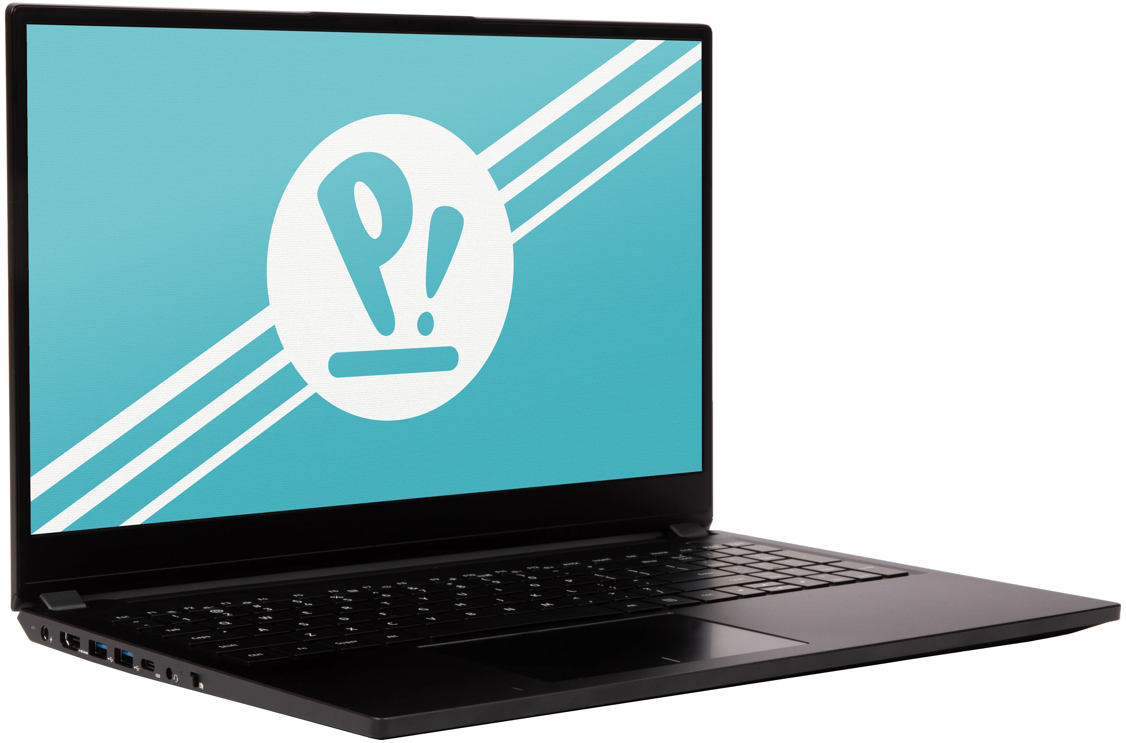
The System76 Pangolin is a laptop with the following specifications:
- CPU
- Supports AMD Ryzen (Phoenix) Mobile CPUs
- BIOS
- Winbond W25R256JW flash chip
- WSON-8 form factor
- Programmed with System76 firmware (non-open)
- Winbond W25R256JW flash chip
- EC
- ITE IT5571
- Programmed with non-open EC firmware
- ITE IT5571
- Graphics
- GPU: AMD Radeon 780M
- eDP display: 16.1" 1920x1080@60Hz LCD
- LCD panel: Innolux N161HCA-EA3 (or equivalent)
- External video output:
- 1x HDMI 2.0
- 1x DisplayPort 1.4 over USB-C
- Memory
- 32GB (4x8GB) LPDDR5 (on-board) @ 6400 MHz
- Micron MT62F2G32D8DR-031
- SK Hynix H9JCNNNFA5MLYR-N6E
- ...or other equivalent.
- 32GB (4x8GB) LPDDR5 (on-board) @ 6400 MHz
- Networking
- Gigabit Ethernet
- M.2 PCIe WiFi/Bluetooth
- Power
- 90W (19V, 4.74A) DC-in port
- Barrel size: 5.5mm (outer), 2.5mm (inner)
- Included AC adapter: ShenZhen SOY-1900474
- AC power cord type: IEC C13
- USB-C charging compatible with 90W+ charger
- 70Wh 3-cell Lithium-Ion battery
- Model number: 628467-3S1P
- 90W (19V, 4.74A) DC-in port
- Sound
- Internal speakers & microphone
- Combined headphone & microphone 3.5mm jack
- HDMI audio
- Storage
- 2x M.2 (PCIe NVMe Gen 4)
- SD card reader
- USB
- 1x USB 3.2 Gen 2 Type-C
- Supports DisplayPort over USB-C
- Supports USB-C charging (USB-PD)
- Does not support Thunderbolt
- 3x USB 3.2 Gen 1 Type-A
- 1x USB 3.2 Gen 2 Type-C
- Dimensions
- 1.80cm x 37.06cm x 24.79cm, 1.79kg
Pangolin (External Overview)
Left side:

Right side:

Front side:

Back side:

Keyboard & touchpad:

Lid:

Materials
| Part | Material |
|---|---|
| LCD back cover (lid) | Magnesium Alloy |
| LCD front cover (bezel) | Plastic |
| Top case (palm rests/port covers) | Magnesium Alloy |
| Bottom panel | Magnesium Alloy |
LED indicators:
| Icon | State | Description |
|---|---|---|
 | On | Charging |
| Off | Fully charged | |
 | On | Webcam disabled (privacy mode on) |
| Off | Webcam enabled (privacy mode off) | |
 | On | Powered on |
| Pulsing | Suspended | |
| Off | Powered off |
Keyboard shortcuts
| Key | Shortcut | Action |
|---|---|---|
 | Fn+F1 | Mute |
 | Fn+F2 | Volume down |
 | Fn+F3 | Volume up |
 | Fn+F6 | Toggle trackpad |
 | Fn+F7 | Cycle keyboard brightness |
 | Fn+F9 | Toggle airplane mode |
 | Fn+F10 | Toggle displays |
 | Fn+F11 | Screen brightness down |
 | Fn+F12 | Screen brightness up |
Pangolin (Internal Overview)
Bottom components and connectors:

- M.2 SSDs are highlighted in dark green
- Wireless card is highlighted in dark blue
- LCD panel connector is highlighted in red*
- CMOS battery connector is highlighted in yellow
- Main battery connector is highlighted in purple
- Fan connectors are highlighted in orange
- BIOS flash chip (U4) is highlighted in black
- Speaker connector is highlighted in cyan
- Touchpad connector is highlighted in white*
- Keyboard connector is highlighted in light green*
- Keyboard backlight connector is highlighted in pink*
* Marked connectors are protected by black tape by default.
Pangolin (Parts & Repairs)
Many components in your Pangolin can be upgraded or replaced as necessary. Follow these step-by-step guides for instructions:
- Replacing an M.2/NVMe SSD
- Removing the bottom cover
- Removing the battery
- Replacing the WiFi/Bluetooth module
- Replacing the CMOS battery
- Replacing the fans/heatsink/thermal paste
- Replacing the speakers
Replacing an M.2/NVMe SSD:
This model supports two M.2 SSDs. Both slots support PCIe NVMe Generation 4 connections and M.2 size 2280.
Tools required: Cross-head (Phillips) screwdriver
Time estimate: 3 minutes
Difficulty: Easy ●
Steps to replace the M.2 drive:
- Unscrew the M.2 access door screw.
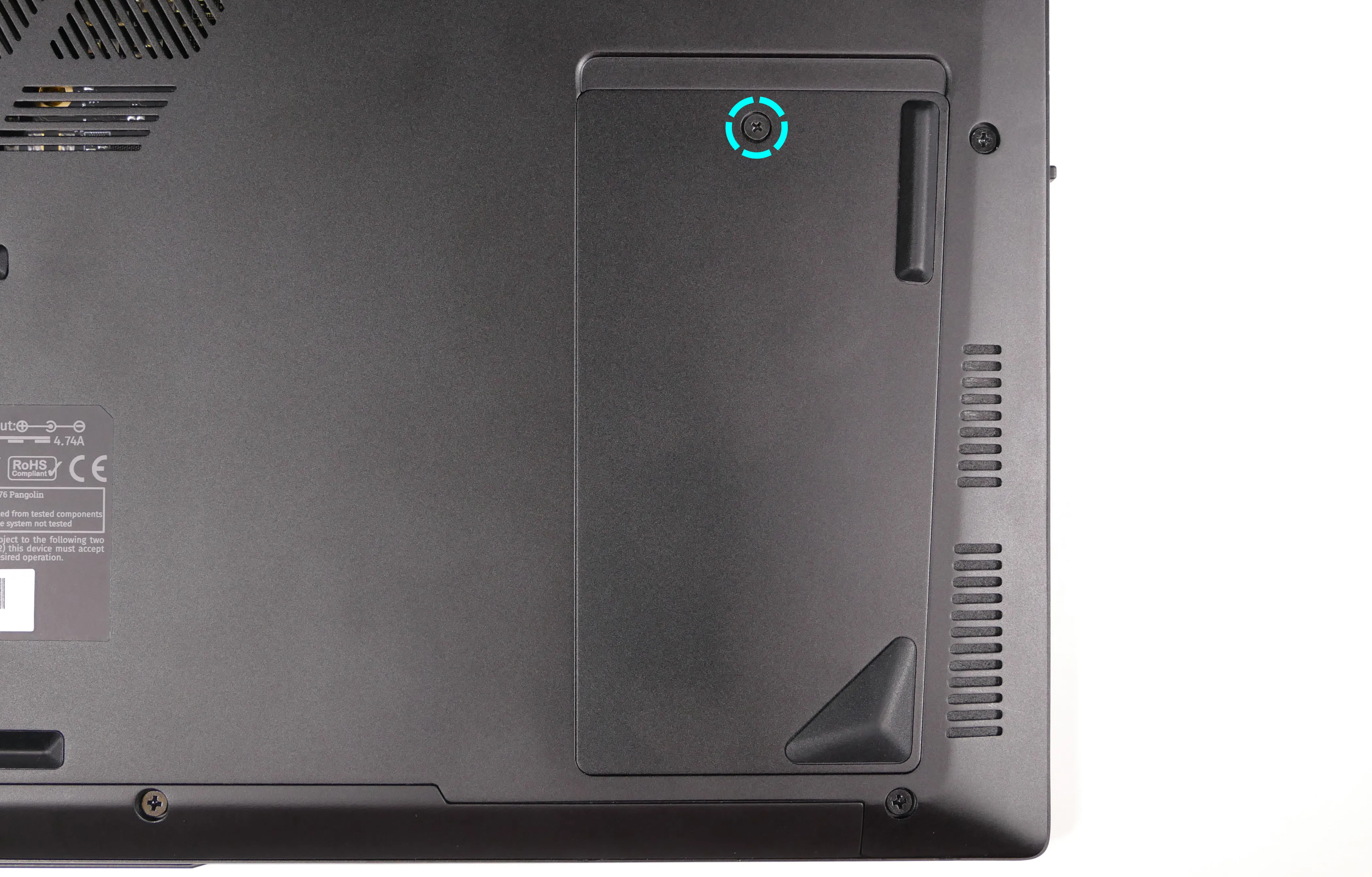
- Pull the M.2 access door off, starting from the top (larger side).
- A flat, plastic tool can be used to pry the edge of the door up.
- If the door is difficult to remove, the M.2 drives can alternatively be accessed by removing the bottom cover.
- Unscrew the retainer screw opposite the M.2 slot.

- Remove the existing M.2 drive by pulling it out of the slot.
- Insert the new M.2 drive into the slot and hold it in place.
- If a slot is being used for the first time, the spare thermal pad (which is included in the Pangolin's box) can be applied to the silver backplate before placing the drive down on top of it.

- If a slot is being used for the first time, the spare thermal pad (which is included in the Pangolin's box) can be applied to the silver backplate before placing the drive down on top of it.
- Replace the retainer screw.
Removing the bottom cover:
Removing the cover is required to access the internal components. Prior to removing the cover, ensure the AC power is unplugged and all peripherals (including SD cards and USB drives) are unplugged or removed from the system.
Part numbers:
- The bottom panel's part number is
NM16ARB-D.
Tools required: Cross-head (Phillips) screwdriver
Time estimate: 5 minutes
Difficulty: Easy ●
Steps to remove the bottom cover:
- Place the machine lid-side down.
- Use a soft surface (such as a towel) to avoid scratches.
- Remove the 11 bottom panel screws.
- The M.2 access door screw does not need to be removed.

- Lift the bottom panel off, starting from the hinges in the back.
Removing the battery:
The battery provides primary power whenever the system is unplugged.
Part numbers:
- The battery's model number is
628467-3S1P, and the original part number is3ICP7/85/67.- Third-party battery sellers may list one or both of these numbers, and may offer other compatible part numbers with the same model number.
- You can also contact System76 to purchase a replacement battery.
Tools required: Cross-head (Phillips) screwdriver
Time estimate: 10 minutes
Difficulty: Easy ●
Steps to remove the battery:
- Follow the steps above to remove the bottom cover.
- Remove the four battery screws, highlighted green below.

- Unplug the battery connector (highlighted cyan above) and lift the battery out of the chassis.
Replacing the wireless card:
Your Pangolin's WiFi and Bluetooth are both handled by the same module. It is a standard M.2 2230 slot with PCIe and USB interfaces (E-key).
Part numbers:
- The standard wireless card is a Mediatek
MT7921K.
Tools required: Cross-head (Phillips) screwdriver
Time estimate: 12 minutes
Difficulty: Medium ●
Steps to replace the WiFi/Bluetooth module:
- Follow the steps above to remove the bottom cover.
- Locate the wireless module. Remove any clear and/or black tape that is securing the wires and card.

- Gently remove the two antennas (highlighted red above) by pulling them up and away from the wireless card.
- Remove the retaining screw opposite the M.2 slot, highlighted yellow above.
- The wireless card will pop up at an angle. Remove the card from the M.2 slot.
- Insert the new wireless card into the M.2 slot at an angle.
- Replace the retaining screw.
- Attach the two antennas by aligning the circular fittings and pressing onto the wireless card. The connectors will snap into place. Use caution when attaching the connectors; the pins can bend, break, or snap.
Replacing the CMOS battery:
The CMOS battery supplies power to the system's CMOS chip. UEFI settings and the computer's hardware clock are stored on the CMOS. If your system doesn't boot, you can reset the CMOS to force a low-level hardware reset. If your clock is constantly resetting, it's likely your CMOS battery needs to be replaced.
Warning (ingestion hazard): Keep batteries out of reach of children. Death or serious injury can occur if ingested. If a battery is suspected to be swallowed or inserted inside any part of the body, seek immediate medical attention. In the US, you can also call the National Battery Ingestion Hotline for guidance: 1 (800) 498-8666
Part numbers:
- The CMOS battery is a standard 3V EVE CR2032 battery.
Tools required: Cross-head (Phillips) screwdriver
Time estimate: 10 minutes
Difficulty: Medium ●
Steps to replace the CMOS battery:
- Follow the steps above to remove the bottom cover.
- Unplug the white connector attaching the CMOS battery to the motherboard (highlighted green below.)

- If you are replacing the CMOS battery, carefully peel it away from the adhesive holding it to the chassis.
- To clear the CMOS, disconnect the main battery, open the lid of the machine, and hold down the power button for at least 15 seconds to discharge any residual energy in the system.
- Re-connect the CMOS battery and the main battery, and replace the bottom panel.
- Power up the machine. The system may power itself off and on after initial boot; this is normal behavior when the CMOS has been reset.
Replacing the cooling system:
The Pangolin 14 has a fan and heatsink assembly to cool the CPU. The fans and heatsink are held together with adhesive; it is possible to replace the fans individually, but removing the entire assembly is recommended to perform service.
If the fan becomes noisy and cleaning it out doesn't fix the issue, you may need a new fan. Contact support to start a warranty claim or parts purchase.
Depending on your climate and the age of the machine, it may be necessary to apply new thermal paste between the CPU and the heatsink. Thermal paste helps facilitate effective heat transfer between the CPU and the cooling equipment.
Part numbers:
- The heatsink's part number is
01.WW7.NM16ACPD002. - The left fan's part number is
01.SS9.NM16ACPD000, and its model number isB7007ASHNF2101TN. - The right fan's part number is
01.SS9.NM16ACPD001, and its model number isB7007ASHSF2101TN. - The complete fan/heatsink assembly is also known as
NM16AC-AC928-PEAK.
Tools required: Cross-head (Phillips) screwdriver, thermal paste
Time estimate: 20 minutes
Difficulty: High ●
Steps to replace the fan/heatsink/thermal paste:
- Follow the steps above to remove the bottom cover.
- Remove any black tape that may be covering the fan screws and wires.
- Remove the six fan screws, highlighted green below.

- Unplug the fan connectors, highlighted cyan above.
- Unscrew the three heatsink screws, highlighted red above.
- The heatsink screws are held captive and will not come out of the heatsink.
- Remove the fan and heatsink assembly from the system, being careful not to bend the heatsink pipe. It may take some pressure to break the seal of the thermal paste.
- The fans are held onto the heatsink with adhesive strips on both the top and bottom; if they come loose, place them back into position between the strips before reinstalling the fan/heatsink assembly.
- Using a paper towel, remove the existing silver thermal paste. You may also use a small amount of rubbing alcohol if the old paste is dried or difficult to remove.
- The pink thermal pads do not need to be removed.

- After cleaning the CPU and heatsink, apply a small line of thermal paste directly onto the CPU chip.

- Carefully replace the heatsink.
- Tighten the three heatsink screws.
- Replace the fan screws, stick the adhesive sheet back on, and plug in the fan connectors.
Replacing the speakers:
The system has two bottom-firing speakers. The speakers are a connected set, and must be replaced together.
Tools required: Cross-head (Phillips) screwdriver
Time estimate: 10 minutes
Difficulty: Medium ●
Steps to replace the speakers:
- Follow the steps above to remove the bottom cover.
- Disconnect the left speaker (on the right side when the machine is upside-down) from the motherboard.
- This can alternatively be done after freeing the speaker.

- Pull both speakers up and off of the plastic posts.
- Remove any tape necessary to free the wire between the left and right speakers.
- Slide the new speakers onto the plastic posts, run the wire between the speakers through the channels in the chassis, and connect the left speaker to the motherboard.
Pangolin (pang13)
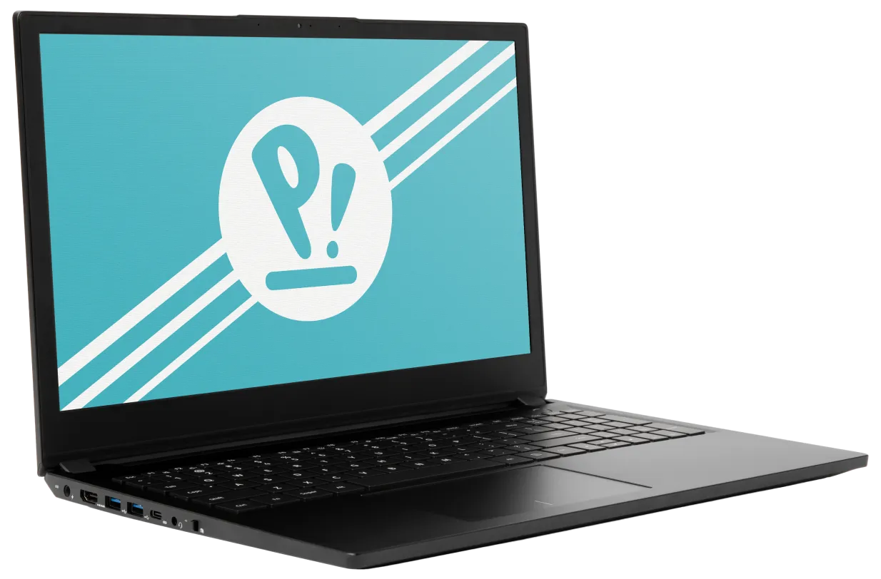
The System76 Pangolin is a laptop with the following specifications:
- CPU
- Supports AMD Ryzen (Rembrandt) Mobile CPUs
- BIOS
- Winbond W25R256JW flash chip
- WSON-8 form factor
- Programmed with System76 firmware (non-open)
- Winbond W25R256JW flash chip
- EC
- ITE IT5571
- Programmed with non-open EC firmware
- ITE IT5571
- Graphics
- GPU: AMD Radeon 680M
- eDP display: 15.6" 1920x1080@144Hz LCD
- LCD panel: Innolux N156HRA-EA1 (or equivalent)
- External video output:
- 1x HDMI 2.0
- 1x DisplayPort 1.4 over USB-C
- Memory
- 32GB (4x8GB) LPDDR5 (on-board) @ 6400 MHz
- Micron MT62F2G32D8DR-031
- SK Hynix H9JCNNNFA5MLYR-N6E
- ...or other equivalent.
- 32GB (4x8GB) LPDDR5 (on-board) @ 6400 MHz
- Networking
- Gigabit Ethernet
- M.2 PCIe WiFi/Bluetooth
- Mediatek MT7921K
- Power
- 90W (19V, 4.74A) DC-in port
- Barrel size: 5.5mm (outer), 2.5mm (inner)
- Included AC adapter: ShenZhen SOY-1900474
- AC power cord type: IEC C13
- USB-C charging compatible with 90W+ charger
- 70Wh 3-cell Lithium-Ion battery
- Model number: 628467-3S1P
- 90W (19V, 4.74A) DC-in port
- Sound
- Internal speakers & microphone
- Combined headphone & microphone 3.5mm jack
- HDMI audio
- Storage
- 2x M.2 (PCIe NVMe Gen 4)
- SD card reader
- USB
- 1x USB 3.2 Gen 2 Type-C
- Supports DisplayPort over USB-C
- Supports USB-C charging (USB-PD)
- Does not support Thunderbolt
- 3x USB 3.2 Gen 1 Type-A
- 1x USB 3.2 Gen 2 Type-C
- Dimensions
- 1.80cm x 37.06cm x 24.79cm, 1.79kg
Pangolin (External Overview)
Left side:

Right side:

Front side:

Back side:

Keyboard & touchpad:

Lid:

Materials
| Part | Material |
|---|---|
| LCD back cover (lid) | Magnesium Alloy |
| LCD front cover (bezel) | Plastic |
| Top case (palm rests/port covers) | Magnesium Alloy |
| Bottom panel | Magnesium Alloy |
LED indicators:
| Icon | State | Description |
|---|---|---|
 | On | Charging |
| Off | Fully charged | |
 | On | Webcam disabled (privacy mode on) |
| Off | Webcam enabled (privacy mode off) | |
 | On | Powered on |
| Pulsing | Suspended | |
| Off | Powered off |
Keyboard shortcuts
| Key | Shortcut | Action |
|---|---|---|
 | Fn+F1 | Mute |
 | Fn+F2 | Volume down |
 | Fn+F3 | Volume up |
 | Fn+F6 | Toggle trackpad |
 | Fn+F7 | Cycle keyboard brightness |
 | Fn+F9 | Toggle airplane mode |
 | Fn+F10 | Toggle displays |
 | Fn+F11 | Screen brightness down |
 | Fn+F12 | Screen brightness up |
Pangolin (Internal Overview)
Bottom components and connectors:

- M.2 SSDs are highlighted in dark green
- Wireless card is highlighted in dark blue
- LCD panel connector is highlighted in red
- CMOS battery connector is highlighted in yellow
- Main battery connector is highlighted in purple
- Fan connectors are highlighted in orange
- Left fan connector is underneath the thermal adhesive sheet
- BIOS flash chip (U4) is highlighted in black
- BIOS flash chip is underneath the thermal adhesive sheet
- Speaker connector is highlighted in cyan
- Touchpad connector is highlighted in white
- Keyboard connector is highlighted in light green
- Keyboard backlight connector is highlighted in pink
Pangolin (Parts & Repairs)
Many components in your Pangolin can be upgraded or replaced as necessary. Follow these step-by-step guides for instructions:
- Replacing an M.2/NVMe SSD
- Removing the bottom cover
- Removing the battery
- Replacing the WiFi/Bluetooth module
- Replacing the CMOS battery
- Replacing the fans/heatsink/thermal paste
- Replacing the speakers
Replacing an M.2/NVMe SSD:
This model supports two M.2 SSDs. Both slots support PCIe NVMe Generation 4 connections and M.2 size 2280.
Tools required: Cross-head (Phillips) screwdriver
Time estimate: 3 minutes
Difficulty: Easy ●
Steps to replace the M.2 drive:
- Unscrew the M.2 access door screw.

- Pull the M.2 access door off, starting from the top (larger side).
- A flat, plastic tool can be used to pry the edge of the door up.
- If the door is difficult to remove, the M.2 drives can alternatively be accessed by removing the bottom cover.
- Unscrew the retainer screw opposite the M.2 slot.

- Remove the existing M.2 drive by pulling it out of the slot.
- Insert the new M.2 drive into the slot and hold it in place.
- If a slot is being used for the first time, the spare thermal pad (which is included in the Pangolin's box) can be applied to the silver backplate before placing the drive down on top of it.

- If a slot is being used for the first time, the spare thermal pad (which is included in the Pangolin's box) can be applied to the silver backplate before placing the drive down on top of it.
- Replace the retainer screw.
Removing the bottom cover:
Removing the cover is required to access the internal components. Prior to removing the cover, ensure the AC power is unplugged and all peripherals (including SD cards and USB drives) are unplugged or removed from the system.
Tools required: Cross-head (Phillips) screwdriver
Time estimate: 5 minutes
Difficulty: Easy ●
Steps to remove the bottom cover:
- Place the machine lid-side down.
- Use a soft surface (such as a towel) to avoid scratches.
- Remove the 11 bottom panel screws.
- The M.2 access door screw does not need to be removed.

- Lift the bottom panel off, starting from the hinges in the back.
Removing the battery:
The battery provides primary power whenever the system is unplugged.
The model number for the Pangolin 13's battery is 628467-3S1P, and the original part number is 3ICP7/85/67. Third-party battery sellers may list one or both of these numbers, and may offer other compatible part numbers with the same model number. You can also contact System76 to purchase a replacement battery.
Tools required: Cross-head (Phillips) screwdriver
Time estimate: 10 minutes
Difficulty: Easy ●
Steps to remove the battery:
- Follow the steps above to remove the bottom cover.
- Remove the four battery screws, highlighted green below.

- Unplug the battery connector (highlighted cyan above) and lift the battery out of the chassis.
Replacing the wireless card:
Your Pangolin's WiFi and Bluetooth are both handled by the same module. It is a standard M.2 2230 slot with PCIe and USB interfaces (E-key).
Tools required: Cross-head (Phillips) screwdriver
Time estimate: 12 minutes
Difficulty: Medium ●
Steps to replace the WiFi/Bluetooth module:
- Follow the steps above to remove the bottom cover.
- Locate the wireless module. Remove any clear tape that is securing the wires.

- Gently remove the two antennas (highlighted red above) by pulling them up and away from the wireless card.
- Remove the retaining screw opposite the M.2 slot, highlighted yellow above.
- The wireless card will pop up at an angle. Remove the card from the M.2 slot.
- Insert the new wireless card into the M.2 slot at an angle.
- Replace the retaining screw.
- Attach the two antennas by aligning the circular fittings and pressing onto the wireless card. The connectors will snap into place. Use caution when attaching the connectors; the pins can bend, break, or snap.
Replacing the CMOS battery:
The CMOS battery supplies power to the system's CMOS chip. UEFI settings and the computer's hardware clock are stored on the CMOS. If your system doesn't boot, you can reset the CMOS to force a low-level hardware reset. If your clock is constantly resetting, it's likely your CMOS battery needs to be replaced.
Warning (ingestion hazard): Keep batteries out of reach of children. Death or serious injury can occur if ingested. If a battery is suspected to be swallowed or inserted inside any part of the body, seek immediate medical attention. In the US, you can also call the National Battery Ingestion Hotline for guidance: 1 (800) 498-8666
Tools required: Cross-head (Phillips) screwdriver
Time estimate: 10 minutes
Difficulty: Medium ●
Steps to replace the CMOS battery:
- Follow the steps above to remove the bottom cover.
- Unplug the white connector attaching the CMOS battery to the motherboard (highlighted green below.)

- If you are replacing the CMOS battery, carefully peel it away from the adhesive holding it to the chassis.
- To clear the CMOS, disconnect the main battery, open the lid of the machine, and hold down the power button for at least 15 seconds to discharge any residual energy in the system.
- Re-connect the CMOS battery and the main battery, and replace the bottom panel.
- Power up the machine. The system may power itself off and on after initial boot; this is normal behavior when the CMOS has been reset.
Replacing the cooling system:
The Pangolin 13 has a fan and heatsink assembly to cool the CPU. The fans and heatsink are held together with adhesive; it is possible to replace the fans individually, but removing the entire assembly is recommended to perform service.
If the fan becomes noisy and cleaning it out doesn't fix the issue, you may need a new fan. Contact support to start a warranty claim or parts purchase.
Depending on your climate and the age of the machine, it may be necessary to apply new thermal paste between the CPU and the heatsink. Thermal paste helps facilitate effective heat transfer between the CPU and the cooling equipment.
Tools required: Cross-head (Phillips) screwdriver, thermal paste
Time estimate: 20 minutes
Difficulty: High ●
Steps to replace the fan/heatsink/thermal paste:
- Follow the steps above to remove the bottom cover.
- Peel off the black adhesive sheet covering the heatsink.
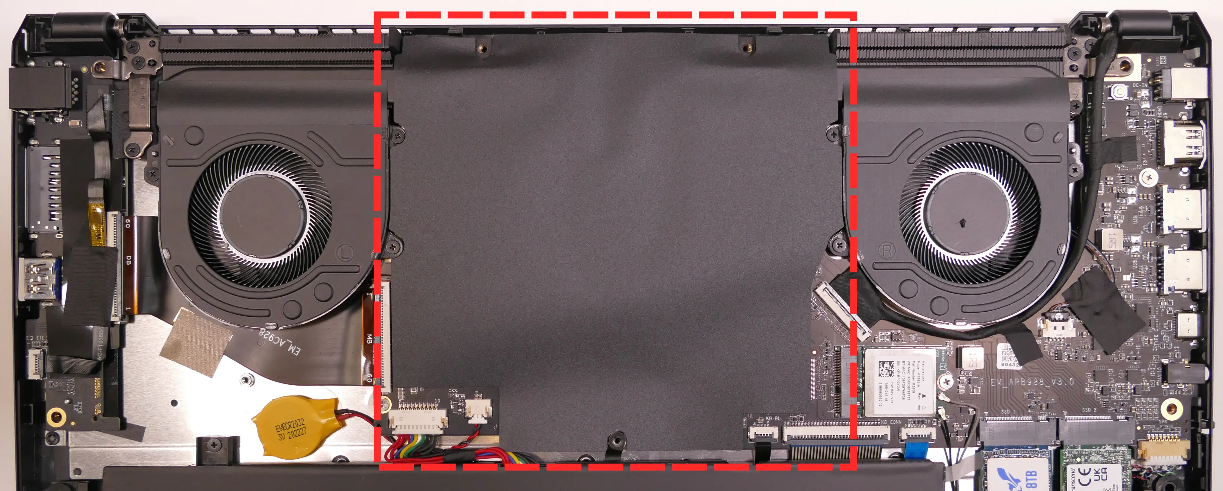
- Remove any black tape that may be covering the fan screws and wires.
- Remove the six fan screws, highlighted green below.

- Unplug the fan connectors, highlighted cyan above.
- Unscrew the three heatsink screws, highlighted red above.
- The heatsink screws are held captive and will not come out of the heatsink.
- Remove the fan and heatsink assembly from the system, being careful not to bend the heatsink pipe. It may take some pressure to break the seal of the thermal paste.
- The fans are held onto the heatsink with adhesive strips on both the top and bottom; if they come loose, place them back into position between the strips before reinstalling the fan/heatsink assembly.
- Using a paper towel, remove the existing silver thermal paste. You may also use a small amount of rubbing alcohol if the old paste is dried or difficult to remove.
- The pink thermal pads do not need to be removed.

- After cleaning the CPU and heatsink, apply a small line of thermal paste directly onto the CPU chip.

- Carefully replace the heatsink.
- Tighten the three heatsink screws.
- Replace the fan screws, stick the adhesive sheet back on, and plug in the fan connectors.
Replacing the speakers:
The system has two bottom-firing speakers. The speakers are a connected set, and must be replaced together.
Tools required: Cross-head (Phillips) screwdriver
Time estimate: 10 minutes
Difficulty: Medium ●
Steps to replace the speakers:
- Follow the steps above to remove the bottom cover.
- Disconnect the left speaker (on the right side when the machine is upside-down) from the motherboard.
- This can alternatively be done after freeing the speaker.

- Pull both speakers up and off of the plastic posts.
- Remove any tape necessary to free the wire between the left and right speakers.
- Slide the new speakers onto the plastic posts, run the wire between the speakers through the channels in the chassis, and connect the left speaker to the motherboard.
Pangolin (pang12)
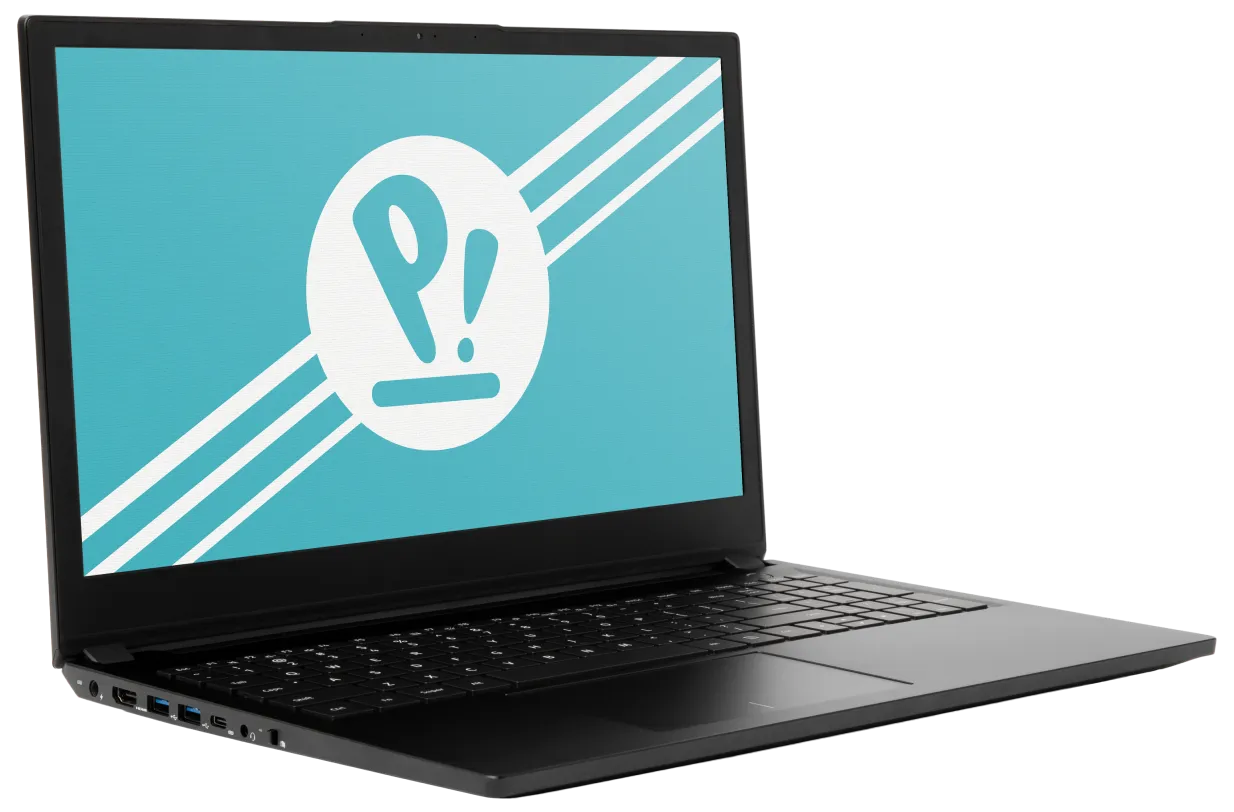
The System76 Pangolin is a laptop with the following specifications:
- CPU
- Supports AMD Ryzen (Rembrandt) Mobile CPUs
- BIOS
- Winbond W25R256JW flash chip
- WSON-8 form factor
- Programmed with System76 firmware (non-open)
- Winbond W25R256JW flash chip
- EC
- ITE IT5571
- Programmed with non-open EC firmware
- ITE IT5571
- Graphics
- GPU: AMD Radeon 680M
- eDP display: 15.6" 1920x1080@144Hz LCD
- LCD panel: Innolux N156HRA-EA1 (or equivalent)
- External video output:
- 1x HDMI 2.0
- 1x DisplayPort 1.4 over USB-C
- Memory
- 32GB (4x8GB) LPDDR5 (on-board) @ 6400 MHz
- Micron MT62F2G32D8DR-031
- SK Hynix H9JCNNNFA5MLYR-N6E
- ...or other equivalent.
- 32GB (4x8GB) LPDDR5 (on-board) @ 6400 MHz
- Networking
- Gigabit Ethernet
- M.2 PCIe WiFi/Bluetooth
- Mediatek MT7921K
- Power
- 65W (19V, 3.42A) DC-in port
- Barrel size: 5.5mm (outer), 2.5mm (inner)
- Included AC adapter: Shenzhen Jihongda JHD-AD065B-190342BA-A
- AC power cord type: IEC C5
- USB-C charging compatible with 65W+ charger
- 70Wh 3-cell Lithium-Ion battery
- Model number: 628467-3S1P
- 65W (19V, 3.42A) DC-in port
- Sound
- Internal speakers & microphone
- Combined headphone & microphone 3.5mm jack
- HDMI audio
- Storage
- 2x M.2 (PCIe NVMe Gen 4)
- SD card reader
- USB
- 1x USB 3.2 Gen 2 Type-C
- Supports DisplayPort over USB-C
- Supports USB-C charging (USB-PD)
- Does not support Thunderbolt
- 3x USB 3.2 Gen 1 Type-A
- 1x USB 3.2 Gen 2 Type-C
- Dimensions
- 1.80cm x 37.06cm x 24.79cm, 1.79kg
Pangolin (External Overview)
Left side:

Right side:

Front side:

Back side:

Keyboard & touchpad:

Lid:

Materials
| Part | Material |
|---|---|
| LCD back cover (lid) | Magnesium Alloy |
| LCD front cover (bezel) | Plastic |
| Top case (palm rests/port covers) | Magnesium Alloy |
| Bottom panel | Magnesium Alloy |
LED indicators:
| Icon | State | Description |
|---|---|---|
 | On | Charging |
| Off | Fully charged | |
 | On | Webcam disabled (privacy mode on) |
| Off | Webcam enabled (privacy mode off) | |
 | On | Powered on |
| Pulsing | Suspended | |
| Off | Powered off |
Keyboard shortcuts
| Key | Shortcut | Action |
|---|---|---|
 | Fn+F1 | Mute |
 | Fn+F2 | Volume down |
 | Fn+F3 | Volume up |
 | Fn+F6 | Toggle trackpad |
 | Fn+F7 | Cycle keyboard brightness |
 | Fn+F9 | Toggle airplane mode |
 | Fn+F10 | Toggle displays |
 | Fn+F11 | Screen brightness down |
 | Fn+F12 | Screen brightness up |
Pangolin (Internal Overview)
Bottom components and connectors:

- M.2 SSDs are highlighted in dark green
- Wireless card is highlighted in dark blue
- LCD panel connector is highlighted in red
- CMOS battery connector is highlighted in yellow
- Main battery connector is highlighted in purple
- Fan connectors are highlighted in orange
- BIOS flash chip (U4) is highlighted in black
- Speaker connector is highlighted in cyan
- Touchpad connector is highlighted in white
- Keyboard connector is highlighted in light green
- Keyboard backlight connector is highlighted in pink
Pangolin (Parts & Repairs)
Many components in your Pangolin can be upgraded or replaced as necessary. Follow these step-by-step guides for instructions:
- Replacing an M.2/NVMe SSD
- Removing the bottom cover
- Removing the battery
- Replacing the WiFi/Bluetooth module
- Replacing the CMOS battery
- Replacing the fans/heatsink/thermal paste
- Replacing the speakers
Replacing an M.2/NVMe SSD:
This model supports two M.2 SSDs. Both slots support PCIe NVMe Generation 4 connections and M.2 size 2280.
Tools required: Cross-head (Phillips) screwdriver
Time estimate: 3 minutes
Difficulty: Easy ●
Steps to replace the M.2 drive:
- Unscrew the M.2 access door screw.

- Pull the M.2 access door off, starting from the top (larger side).
- A flat, plastic tool can be used to pry the edge of the door up.
- If the door is difficult to remove, the M.2 drives can alternatively be accessed by removing the bottom cover.
- Unscrew the retainer screw opposite the M.2 slot.

- Remove the existing M.2 drive by pulling it out of the slot.
- Insert the new M.2 drive into the slot and hold it in place.
- If a slot is being used for the first time, the spare thermal pad (which is included in the Pangolin's box) can be applied to the silver backplate before placing the drive down on top of it.
- Replace the retainer screw.
Removing the bottom cover:
Removing the cover is required to access the internal components. Prior to removing the cover, ensure the AC power is unplugged and all peripherals (including SD cards and USB drives) are unplugged or removed from the system.
Tools required: Cross-head (Phillips) screwdriver
Time estimate: 5 minutes
Difficulty: Easy ●
Steps to remove the bottom cover:
- Place the machine lid-side down.
- Use a soft surface (such as a towel) to avoid scratches.
- Remove the 11 bottom panel screws.
- The M.2 access door screw does not need to be removed.

- Lift the bottom panel off, starting from the hinges in the back.
Removing the battery:
The battery provides primary power whenever the system is unplugged.
The model number for the Pangolin 12's battery is 628467-3S1P, and the original part number is 3ICP7/85/67. Third-party battery sellers may list one or both of these numbers, and may offer other compatible part numbers with the same model number. You can also contact System76 to purchase a replacement battery.
Tools required: Cross-head (Phillips) screwdriver
Time estimate: 10 minutes
Difficulty: Easy ●
Steps to remove the battery:
- Follow the steps above to remove the bottom cover.
- Remove the four battery screws, highlighted green below.

- Unplug the battery connector (highlighted cyan above) and lift the battery out of the chassis.
Replacing the wireless card:
Your Pangolin's WiFi and Bluetooth are both handled by the same module. It is a standard M.2 2230 slot with PCIe and USB interfaces (E-key).
Tools required: Cross-head (Phillips) screwdriver
Time estimate: 12 minutes
Difficulty: Medium ●
Steps to replace the WiFi/Bluetooth module:
- Follow the steps above to remove the bottom cover.
- Locate the wireless module. Remove any clear tape that is securing the wires.

- Gently remove the two antennas (highlighted red above) by pulling them up and away from the wireless card.
- Remove the retaining screw opposite the M.2 slot, highlighted yellow above.
- The wireless card will pop up at an angle. Remove the card from the M.2 slot.
- Insert the new wireless card into the M.2 slot at an angle.
- Replace the retaining screw.
- Attach the two antennas by aligning the circular fittings and pressing onto the wireless card. The connectors will snap into place. Use caution when attaching the connectors; the pins can bend, break, or snap.
Replacing the CMOS battery:
The CMOS battery supplies power to the system's CMOS chip. UEFI settings and the computer's hardware clock are stored on the CMOS. If your system doesn't boot, you can reset the CMOS to force a low-level hardware reset. If your clock is constantly resetting, it's likely your CMOS battery needs to be replaced.
Warning (ingestion hazard): Keep batteries out of reach of children. Death or serious injury can occur if ingested. If a battery is suspected to be swallowed or inserted inside any part of the body, seek immediate medical attention. In the US, you can also call the National Battery Ingestion Hotline for guidance: 1 (800) 498-8666
Tools required: Cross-head (Phillips) screwdriver
Time estimate: 10 minutes
Difficulty: Medium ●
Steps to replace the CMOS battery:
- Follow the steps above to remove the bottom cover.
- Unplug the white connector attaching the CMOS battery to the motherboard (highlighted green below.)

- If you are replacing the CMOS battery, carefully peel it away from the adhesive holding it to the chassis.
- To clear the CMOS, disconnect the main battery, open the lid of the machine, and hold down the power button for at least 15 seconds to discharge any residual energy in the system.
- Re-connect the CMOS battery and the main battery, and replace the bottom panel.
- Power up the machine. The system may power itself off and on after initial boot; this is normal behavior when the CMOS has been reset.
Replacing the cooling system:
The Pangolin 12 has a fan and heatsink assembly to cool the CPU. The fans and heatsink are held together with adhesive; it is possible to replace the fans individually, but removing the entire assembly is recommended to perform service.
If the fan becomes noisy and cleaning it out doesn't fix the issue, you may need a new fan. Contact support to start a warranty claim or parts purchase.
Depending on your climate and the age of the machine, it may be necessary to apply new thermal paste between the CPU and the heatsink. Thermal paste helps facilitate effective heat transfer between the CPU and the cooling equipment.
Tools required: Cross-head (Phillips) screwdriver, thermal paste
Time estimate: 20 minutes
Difficulty: High ●
Steps to replace the fan/heatsink/thermal paste:
- Follow the steps above to remove the bottom cover.
- If a black adhesive sheet is present between the fans, peel it off. Also remove any black tape that may be covering the fan screws and wires.
- Remove the six fan screws, highlighted green below.

- Unplug the fan connectors, highlighted cyan above.
- Unscrew the three heatsink screws, highlighted red above.
- The heatsink screws are held captive and will not come out of the heatsink.
- Remove the fan and heatsink assembly from the system, being careful not to bend the heatsink pipe. It may take some pressure to break the seal of the thermal paste.
- The fans are held onto the heatsink with adhesive strips on both the top and bottom; if they come loose, place them back into position between the strips before reinstalling the fan/heatsink assembly.
- Using a paper towel, remove the existing thermal paste. You may also use a small amount of rubbing alcohol if the old paste is dried or difficult to remove.

- After cleaning the CPU and heatsink, apply a small line of thermal paste directly onto the CPU chip.

- Carefully replace the heatsink.
- Tighten the three heatsink screws.
- Replace the fan screws and plug in the fan connectors.
Replacing the speakers:
The system has two bottom-firing speakers. The speakers are a connected set, and must be replaced together.
Tools required: Cross-head (Phillips) screwdriver
Time estimate: 10 minutes
Difficulty: Medium ●
Steps to replace the speakers:
- Follow the steps above to remove the bottom cover.
- Disconnect the left speaker (on the right side when the machine is upside-down) from the motherboard.
- This can alternatively be done after freeing the speaker.

- Pull both speakers up and off of the plastic posts.
- Remove any tape necessary to free the wire between the left and right speakers.
- Slide the new speakers onto the plastic posts, run the wire between the speakers through the channels in the chassis, and connect the left speaker to the motherboard.
Pangolin (pang11)
The System76 Pangolin is a laptop with the following specifications:
- CPU
- Supports AMD Ryzen (Lucienne) Mobile CPUs
- BIOS
- W74M12JWSSIQ flash chip
- SOIC-8 form factor
- Programmed with System76 firmware (non-open)
- W74M12JWSSIQ flash chip
- EC
- ITE IT5570
- Programmed with non-open EC firmware
- ITE IT5570
- Graphics
- GPU: AMD Radeon Vega 7
- eDP display: 15.6" 1920x1080@60Hz LCD
- LCD panel: Innolux N156HCA-EA1 (or equivalent)
- External video output: 1x HDMI 2.0
- Memory
- Up to 64GB (2x32GB) dual-channel DDR4 SO-DIMMs @ 3200 MHz
- Networking
- Gigabit Ethernet
- M.2 PCIe/CNVi WiFi/Bluetooth
- Power
- 65W (19V, 3.42A) DC-in port
- Barrel size: 5.5mm (outer), 2.5mm (inner)
- Included AC adapter: Chicony A18-065N3A
- AC power cord type: IEC C5
- 49Wh 4-cell Lithium-Ion battery
- Model number: NL40BAT-4
- 65W (19V, 3.42A) DC-in port
- Sound
- Internal speakers & microphone
- Combined headphone & microphone 3.5mm jack
- HDMI audio
- Storage
- 1x M.2 (PCIe NVMe or SATA)
- MicroSD card reader
- USB
- 1x USB 3.2 Gen 2 Type-C
- No Thunderbolt, DisplayPort, or charging capabilities.
- 1x USB 3.1 Gen 1 Type-A
- 2x USB 2.0 Type-A
- 1x USB 3.2 Gen 2 Type-C
- Dimensions
- 1.99cm x 36.04cm x 23.93cm, 1.65kg
Pangolin (External Overview)
Left side:

Right side:

Front side:

Back side:

Materials
| Part | Material |
|---|---|
| LCD back cover (lid) | Aluminum |
| LCD front cover (bezel) | Plastic |
| Top case (palm rests/port covers) | Plastic |
| Bottom panel | Aluminum |
LED indicators
| Icon | Color | Description |
|---|---|---|
 | Orange | Plugged in, battery charging |
| Green | Plugged in, battery fully charged | |
| Blinking orange | Battery critically low |
Keyboard shortcuts
| Key | Shortcut | Action |
|---|---|---|
 | Fn+F1 | Toggle trackpad |
 | Fn+F2 | Toggle built-in LCD |
 | Fn+F3 | Mute |
 | Fn+F5 | Volume down |
 | Fn+F6 | Volume up |
 | Fn+F7 | Toggle displays |
 | Fn+F8 | Screen brightness down |
 | Fn+F9 | Screen brightness up |
 | Fn+F10 | Toggle webcam |
 | Fn+F11 | Toggle airplane mode |
 | Fn+F12 | Suspend |
 | Fn+` | Play/Pause |
 | Fn+* | Toggle keyboard backlight |
| / | Fn+/ | Cycle keyboard color |
| - | Fn+- | Decrease keyboard brightness |
| + | Fn++ | Increase keyboard brightness |
| 1 | Fn+1 | Toggle fan between max/automatic |
Pangolin (Internal Overview)
Bottom components and connectors:

- RAM slots are highlighted in dark green
- Wireless card is highlighted in blue
- LCD panel connector is highlighted in red
- CMOS battery connector is highlighted in yellow
- Fan connector is highlighted in orange
- Webcam/microphone connector is highlighted in pink
- Main battery connector is highlighted in light green
- M.2 SSD is highlighted in purple
- Speaker connectors are highlighted in cyan
- Touchpad connector is highlighted in white
- BIOS flash chip (U33) is highlighted in black
Under-keyboard components and connectors:

- Keyboard connector is highlighted in cyan
- Keyboard backlight connector is highlighted in green
- Power button/LED connector is highlighted in orange
Pangolin (Parts & Repairs)
Many components in your Pangolin can be upgraded or replaced as necessary. Follow these step-by-step guides for instructions:
- Removing the bottom cover
- Removing the battery
- Replacing the RAM
- Replacing an M.2/NVMe SSD
- Replacing the WiFi/Bluetooth module
- Replacing the CMOS battery
- Replacing the fans/heatsink/thermal paste
- Replacing the keyboard
Removing the bottom cover:
Removing the cover is required to access the internal components and to remove the keyboard. Prior to removing the cover, ensure the AC power is unplugged and all peripherals (including SD cards and USB drives) are unplugged or removed from the system.
Tools required: Cross-head (Phillips) screwdriver
Time estimate: 5 minutes
Difficulty: Easy ●
Steps to remove the bottom cover:
- Place the machine lid-side down.
- Use a soft surface (such as a towel) to avoid scratches.
- Remove the 12 bottom panel screws.

- Lift the bottom panel off, starting from the hinges in the back.
Removing the battery:
The battery provides primary power whenever the system is unplugged.
The model number for the Pangolin 11's battery is NL40BAT-4, and the original part number is 6-87-NL4CS-41B01. Third-party battery sellers may list one or both of these numbers, and may offer other compatible part numbers with the same model number. You can also contact System76 to purchase a replacement battery.
Tools required: Cross-head (Phillips) screwdriver
Time estimate: 10 minutes
Difficulty: Easy ●
Steps to remove the battery:
- Follow the steps above to remove the bottom cover.
- Remove the four battery screws, highlighted green below.

- Unplug the battery connector (highlighted yellow above) and lift the battery out of the chassis.
Replacing the RAM:
The Pangolin 11 supports up to 64GB (2x32GB) of DDR4 SO-DIMMs running at 3200MHz. If you've purchased new RAM, need to replace your RAM, or are reseating your RAM, follow these steps.
Tools required: Cross-head (Phillips) screwdriver
Time estimate: 10 minutes
Difficulty: Easy ●
Steps to replace the RAM:
- Follow the steps above to remove the bottom cover.
- Press the small tabs on both sides of the RAM simultaneously. The RAM should spring up to an angle.

- Remove the RAM from the slot.
- Insert the new RAM (or reseat the existing RAM) by placing it in the keyed slot and pressing down until it clicks into place.
Replacing an M.2/NVMe SSD:
This model supports one M.2 SSD of size 2280, either SATA III or PCIe NVMe Generation 3.
Tools required: Cross-head (Phillips) screwdriver
Time estimate: 10 minutes
Difficulty: Easy ●
Steps to replace the M.2 drive:
- Follow the steps above to remove the bottom cover.
- Unscrew the retainer screw opposite the M.2 slot.

- Remove the existing M.2 drive by pulling it out of the slot.
- Insert the new M.2 drive into the slot and hold it in place.
- Replace the retainer screw.
- If a square thermal pad was present on the old drive, transfer it to the new drive.
Replacing the wireless card:
Your Pangolin's WiFi and Bluetooth are both handled by the same module. It is a standard M.2 2230 slot with PCIe and USB interfaces (E-key).
Tools required: Cross-head (Phillips) screwdriver
Time estimate: 12 minutes
Difficulty: Medium ●
Steps to replace the WiFi/Bluetooth module:
- Follow the steps above to remove the bottom cover.
- Locate the wireless module. Remove any clear tape that is securing the wires.

- Gently remove the two antennas (highlighted red above) by pulling them up and away from the wireless card.
- Remove the retaining screw opposite the M.2 slot, highlighted yellow above.
- The wireless card will pop up at an angle. Remove the card from the M.2 slot.
- Insert the new wireless card into the M.2 slot at an angle.
- Replace the retaining screw.
- Attach the two antennas by aligning the circular fittings and pressing onto the wireless card. The connectors will snap into place. Use caution when attaching the connectors; the pins can bend, break, or snap.
Replacing the CMOS battery:
The CMOS battery supplies power to the system's CMOS chip. UEFI settings and the computer's hardware clock are stored on the CMOS. If your system doesn't boot, you can reset the CMOS to force a low-level hardware reset. If your clock is constantly resetting, it's likely your CMOS battery needs to be replaced.
Warning (ingestion hazard): Keep batteries out of reach of children. Death or serious injury can occur if ingested. If a battery is suspected to be swallowed or inserted inside any part of the body, seek immediate medical attention. In the US, you can also call the National Battery Ingestion Hotline for guidance: 1 (800) 498-8666
Tools required: Cross-head (Phillips) screwdriver
Time estimate: 10 minutes
Difficulty: Medium ●
Steps to replace the CMOS battery:
- Follow the steps above to remove the bottom cover.
- Unplug the white connector attaching the CMOS battery to the motherboard (highlighted green below.)

- If you are replacing the CMOS battery, carefully peel it away from the adhesive holding it to the motherboard.
- To clear the CMOS, disconnect the main battery, open the lid of the machine, and hold down the power button for at least 15 seconds to discharge any residual energy in the system.
- Re-connect the CMOS battery and the main battery, and replace the bottom panel.
- Power up the machine. The system may power itself off and on after initial boot; this is normal behavior when the CMOS has been reset.
Replacing the cooling system:
The Pangolin 11 has a single fan and heatsink assembly to cool the CPU. Since the fan and heatsink are a single assembly, the fan and heatsink cannot be removed or replaced separately from one another.
If the fan becomes noisy and cleaning it out doesn't fix the issue, you may need a new fan and heatsink assembly. Contact Support to start a warranty claim or parts purchase.
Depending on your climate and the age of the machine, it may be necessary to apply new thermal paste between the CPU and the heatsink. Thermal paste helps facilitate effective heat transfer between the CPU and the cooling equipment.
Tools required: Cross-head (Phillips) screwdriver, thermal paste
Time estimate: 20 minutes
Difficulty: High ●
Steps to replace the fan/heatsink/thermal paste:
- Follow the steps above to remove the bottom cover.
- Remove the two fan screws, highlighted green below.

- Unplug the black fan connector, highlighted cyan above. Remove any clear tape that may be holding the wires in place.
- Remove the three heatsink screws (highlighted red above) in order, starting with #1, then #2, and finally #3.
- Remove the fan and heatsink assembly from the system, being careful not to bend the heatsink pipe. It may take some pressure to break the seal of the thermal paste.
- Using a paper towel, remove the existing thermal paste. You may also use a small amount of rubbing alcohol if the old paste is dried or difficult to remove.

- After cleaning the CPU and heatsink, apply a small line of thermal paste directly onto the CPU chip.

- Carefully replace the heatsink.
- Replace the three heatsink screws, starting with #1, then #2, and finally #3.
- Replace the fan screws and plug in the fan connector.
Replacing the keyboard:
The keyboard can be replaced using the instructions below.
Tools required: Cross-head (Phillips) screwdriver
Time estimate: 10 minutes
Difficulty: Medium ●
Steps to replace the keyboard:
- Follow the steps above to remove the bottom cover.
- Remove the two keyboard screws.

- Open the lid slightly and place the machine on its side.
- Push the screwdriver into the keyboard push point (highlighted cyan above) until the keyboard pops out.

- Set the machine back down and raise the keyboard away from the chassis. The larger ribbon cable is for the keyboard, while the smaller ribbon cable is for the keyboard backlight.

- Flip the black latches upwards to free the ribbon cables.
- Pull the ribbon cables out of the connectors.
- Remove the keyboard and replace it with the new one.
- Carefully slide both ribbon cables into their connectors.
- Flip the black latches back into place to secure the ribbon cables.
- Place the keyboard back into position, starting with the tabs on the bottom edge.
- Secure the rest of the keyboard by pressing down on each of its edges.
- Turn the machine lid-side down again and replace the two keyboard screws.
- Replace the bottom cover.
Pangolin (pang10)
The System76 Pangolin is a laptop with the following specifications:
- CPU
- Supports AMD Ryzen (Renoir) Mobile CPUs
- BIOS
- W74M12JWSSIQ flash chip
- SOIC-8 form factor
- Programmed with System76 firmware (non-open)
- W74M12JWSSIQ flash chip
- EC
- ITE IT5570
- Programmed with non-open EC firmware
- Graphics
- GPU: AMD Radeon Vega 7
- eDP display: 15.6" 1920x1080@60Hz LCD
- LCD panel: LG LP156WFC-SPD1 (or equivalent)
- External video output: 1x HDMI 1.4b
- Memory
- Up to 64GB (2x32GB) dual-channel DDR4 SO-DIMMs @ 3200 MHz
- Networking
- Gigabit Ethernet
- M.2 PCIe/CNVi WiFi/Bluetooth
- Power
- 65W (19V, 3.42A) DC-in port
- Barrel size: 5.5mm (outer), 2.5mm (inner)
- Included AC adapter: Chicony A18-065N3A
- AC power cord type: IEC C5
- 49Wh 4-cell Lithium-Ion battery
- Model number: NL40BAT-4
- 65W (19V, 3.42A) DC-in port
- Sound
- Internal speakers & microphone
- Combined headphone & microphone 3.5mm jack
- HDMI audio
- Storage
- 1x M.2 (PCIe NVMe or SATA)
- MicroSD card reader
- USB
- 1x USB 3.2 Gen 2 Type-C
- No Thunderbolt, DisplayPort, or charging capabilities.
- 1x USB 3.1 Gen 1 Type-A
- 2x USB 2.0 Type-A
- 1x USB 3.2 Gen 2 Type-C
- Dimensions
- 1.99cm x 36.04cm x 23.93cm, 1.65kg
Pangolin (External Overview)
Left side overview:

Right side overview:

LED indicators
| Icon | Color | Description |
|---|---|---|
 | Orange | Plugged in, battery charging |
| Green | Plugged in, battery fully charged | |
| Blinking orange | Battery critically low |
Materials
| Part | Material |
|---|---|
| LCD back cover (lid) | Aluminum |
| LCD front cover (bezel) | Plastic |
| Top case (palm rests/port covers) | Plastic |
| Bottom panel | Aluminum |
Keyboard shortcuts
| Key | Shortcut | Action |
|---|---|---|
 | Fn+F1 | Toggle trackpad |
 | Fn+F2 | Toggle built-in LCD |
 | Fn+F3 | Mute |
 | Fn+F5 | Volume down |
 | Fn+F6 | Volume up |
 | Fn+F7 | Toggle displays |
 | Fn+F8 | Screen brightness down |
 | Fn+F9 | Screen brightness up |
 | Fn+F10 | Toggle webcam |
 | Fn+F11 | Toggle airplane mode |
 | Fn+F12 | Suspend |
 | Fn+` | Play/Pause |
 | Fn+* | Toggle keyboard backlight |
| / | Fn+/ | Cycle keyboard color |
| - | Fn+- | Decrease keyboard brightness |
| + | Fn++ | Increase keyboard brightness |
| 1 | Fn+1 | Toggle fan between max/automatic |
Pangolin (Internal Overview)
Bottom components and connectors:

- RAM slots are highlighted in dark green
- M.2 SSD is highlighted in purple
- Wireless card is highlighted in yellow
- CMOS battery connector is highlighted in pink
- CMOS battery is highlighted in white
- Fan/heatsink module is highlighted in navy
- Fan connector is highlighted in light red
- Webcam/microphone connector is highlighted in orange
- LCD panel connector is highlighted in light green
- Main battery connector is highlighted in cyan
- Main battery is highlighted in brown
- Speaker connectors are highlighted in maroon
- Speakers are highlighted in olive
- Touchpad connector is highlighted in dashed red
- BIOS flash chip (U33) is highlighted in black
Under-keyboard components and connectors:

- Keyboard connector is highlighted in cyan
- Keyboard backlight connector is highlighted in green
- Power button/LED connector is highlighted in orange
Pangolin (Parts & Repairs)
Many components in your Pangolin can be upgraded or replaced as necessary. Follow these step-by-step guides for instructions:
- Removing the bottom cover
- Replacing the keyboard
- Removing the battery
- Replacing the RAM
- Replacing an M.2/NVMe SSD
- Replacing the WiFi/Bluetooth module
- Replacing the CMOS battery
- Replacing the fans/heatsink/thermal paste
Removing the bottom cover:
Removing the cover is required to access the internal components and to remove the keyboard. Prior to removing the cover, ensure the AC power is unplugged and all peripherals (including SD cards and USB drives) are unplugged or removed from the system.
Tools required: Cross-head (Phillips) screwdriver
Time estimate: 5 minutes
Difficulty: Easy ●
Steps to remove the bottom cover:
- Place the machine lid-side down.
- Use a soft surface (such as a towel) to avoid scratches.
- Remove the 12 bottom panel screws.

- Lift the bottom panel off, starting from the hinges in the back.
Replacing the keyboard:
The keyboard can be replaced using the instructions below.
Tools required: Cross-head (Phillips) screwdriver
Time estimate: 10 minutes
Difficulty: Easy ●
Steps to replace the keyboard:
- Follow the steps above to remove the bottom cover.
- Remove the two keyboard retaining screws (highlighted green below).

- Open the lid slightly and place the machine on its side.
- Push the screwdriver into the keyboard push point (highlighted cyan above) until the top edge of the keyboard pops out enough to get your fingers under it.

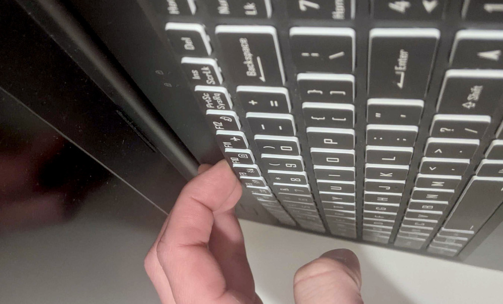
- Set the machine back down, pull the top and side edges of the keyboard up to free them from the chassis, and raise the keyboard away from the chassis. The larger ribbon cable is for the keyboard, while the smaller ribbon cable is for the keyboard backlight.

- Flip the black latches upwards to free the ribbon cables.
- Pull the ribbon cables out of the connectors.
- Remove the keyboard and replace it with the new one.
- Carefully slide both ribbon cables into their connectors.
- Flip the black latches back into place to secure the ribbon cables.
- Place the keyboard back into position, starting with the tabs on the bottom edge.
- Secure the rest of the keyboard by pressing down on each of its edges.
- Turn the machine lid-side down again and replace the two keyboard screws.
- Replace the bottom cover.
Removing the battery:
The battery provides primary power whenever the system is unplugged.
The model number for the Pangolin 10's battery is NL40BAT-4, and the original part number is 6-87-NL4CS-43G01. Third-party battery sellers may list one or both of these numbers, and may offer other compatible part numbers with the same model number. You can also contact System76 to purchase a replacement battery.
Tools required: Cross-head (Phillips) screwdriver
Time estimate: 10 minutes
Difficulty: Easy ●
Steps to remove the battery:
- Follow the steps above to remove the bottom cover.
- Remove the four battery screws, highlighted red below.

- Unplug the battery connector (highlighted green above) and lift the battery out of the chassis.
Replacing the RAM:
The Pangolin 10 supports up to 64GB (2x32GB) of DDR4 SO-DIMMs running at 3200MHz. If you've purchased new RAM, need to replace your RAM, or are reseating your RAM, follow these steps.
Tools required: Cross-head (Phillips) screwdriver
Time estimate: 10 minutes
Difficulty: Easy ●
Steps to replace the RAM:
- Follow the steps above to remove the bottom cover.
- Press the small tabs on both sides of the RAM simultaneously. The RAM should spring up to an angle.

- Remove the RAM from the slot.
- Insert the new RAM (or reseat the existing RAM) by placing it in the keyed slot and pressing down until it clicks into place.
Replacing an M.2/NVMe SSD:
This model supports one M.2 SSD of size 2280, either SATA III or PCIe NVMe Generation 3.
Tools required: Cross-head (Phillips) screwdriver
Time estimate: 10 minutes
Difficulty: Easy ●
Steps to replace the M.2 drive:
- Follow the steps above to remove the bottom cover.
- Unscrew the retainer screw opposite the M.2 slot.

- Remove the existing M.2 drive by pulling it out of the slot.
- Insert the new M.2 drive into the slot and hold it in place.
- Replace the retainer screw.
- If a square brace was present on the old drive, transfer it to the new drive.
Replacing the wireless card:
Your Pangolin's WiFi and Bluetooth are both handled by the same module. It is a standard M.2 2230 slot with PCIe and USB interfaces (E-key).
Tools required: Cross-head (Phillips) screwdriver
Time estimate: 12 minutes
Difficulty: Medium ●
Steps to replace the WiFi/Bluetooth module:
- Follow the steps above to remove the bottom cover.
- Locate the wireless module. Remove any clear tape that is securing the wires.

- Gently remove the two antennas (highlighted red above) by pulling them up and away from the wireless card.
- Remove the retaining screw opposite the M.2 slot, highlighted green above.
- The wireless card will pop up at an angle. Remove the card from the M.2 slot.
- Insert the new wireless card into the M.2 slot at an angle.
- Replace the retaining screw.
- Attach the two antennas by aligning the circular fittings and pressing onto the wireless card. The connectors will snap into place. Use caution when attaching the connectors; the pins can bend, break, or snap.
Replacing the CMOS battery:
The CMOS battery supplies power to the system's CMOS chip. UEFI settings and the computer's hardware clock are stored on the CMOS. If your system doesn't boot, you can reset the CMOS to force a low-level hardware reset. If your clock is constantly resetting, it's likely your CMOS battery needs to be replaced.
Warning (ingestion hazard): Keep batteries out of reach of children. Death or serious injury can occur if ingested. If a battery is suspected to be swallowed or inserted inside any part of the body, seek immediate medical attention. In the US, you can also call the National Battery Ingestion Hotline for guidance: 1 (800) 498-8666
Tools required: Cross-head (Phillips) screwdriver
Time estimate: 10 minutes
Difficulty: Easy ●
Steps to replace the CMOS battery:
- Follow the steps above to remove the bottom cover.
- Unplug the white connector attaching the CMOS battery to the motherboard (highlighted green below.)

- If you are replacing the CMOS battery, carefully peel it away from the adhesive holding it to the motherboard.
- To clear the CMOS, disconnect the main battery, open the lid of the machine, and hold down the power button for at least 15 seconds to discharge any residual energy in the system.
- Re-connect the CMOS battery and the main battery, and replace the bottom panel.
- Power up the machine. The system may power itself off and on after initial boot; this is normal behavior when the CMOS has been reset.
Replacing the cooling system:
The Pangolin 10 has a single fan and heatsink assembly to cool the CPU. Since the fan and heatsink are a single assembly, the fan and heatsink cannot be removed or replaced separately from one another.
If the fan becomes noisy and cleaning it out doesn't fix the issue, you may need a new fan and heatsink assembly. Contact Support to start a warranty claim or parts purchase.
Depending on your climate and the age of the machine, it may be necessary to apply new thermal paste between the CPU and the heatsink. Thermal paste helps facilitate effective heat transfer between the CPU and the cooling equipment.
Tools required: Cross-head (Phillips) screwdriver, thermal paste
Time estimate: 20 minutes
Difficulty: High ●
Steps to replace the fan:
- Follow the steps above to remove the bottom cover.
- Remove the two fan screws, highlighted green below.

- Unplug the black fan connector, highlighted cyan above. Remove any clear tape that may be holding the wires in place.
- Remove the three heatsink screws (highlighted red above) in order, starting with #1, then #2, and finally #3.
- Remove the fan and heatsink assembly from the system, being careful not to bend the heatsink pipe. It may take some pressure to break the seal of the thermal paste.
- Using a paper towel, remove the existing thermal paste. You may also use a small amount of rubbing alcohol to moisten the paper towel if the old paste is dried or difficult to remove.

- After cleaning the CPU and heatsink, apply a small amount of thermal paste directly onto the CPU chip.

- Carefully replace the heatsink.
- Replace the three heatsink screws, starting with #1, then #2, and finally #3.
- Replace the fan screws and plug in the fan connector.
Serval WS (serw13)
The System76 Serval WS is a laptop with the following specifications:
- CPU
- Supports Intel 13th & 14th Generation (Raptor Lake) CPUs
- Chipset
- BIOS
- GigaDevice GD25B256EYIGR
- WSON-8 form factor
- Programmed with System76 Open Firmware
- GigaDevice GD25B256EYIGR
- EC
- ITE IT5570E
- Programmed with System76 EC
- Graphics
- GPU options:
- NVIDIA GeForce RTX 4070
- NVIDIA GeForce RTX 4060
- eDP display:
- 17.3" 3840x2160@144Hz
- LCD panel: AUO B173ZAN03.0 (or equivalent)
- 17.3" 2560x1440@240Hz LCD
- LCD panel: BOE NE173QHM-NZ1 (or equivalent)
- 15.6" 1920x1080@165Hz LCD
- LCD panel: BOE NV156FHM-NY8 (or equivalent)
- 17.3" 3840x2160@144Hz
- External video outputs:
- 1x HDMI 2.1a
- 1x Mini DisplayPort 1.4
- 1x DisplayPort 1.4 over USB-C
- GPU options:
- Memory
- Up to 96GB (2x48GB) dual-channel DDR5 SO-DIMMs @ 5600 MHz
- Networking
- 2.5-Gigabit Ethernet
- M.2 PCIe/CNVi WiFi/Bluetooth options:
- Intel Wi-Fi 7 BE200
- Bluetooth 5.4
- Intel Wi-Fi 6E AX210/AX211
- Bluetooth 5.3
- Intel Wi-Fi 7 BE200
- Power
- 280W (20V, 14A) DC-in port
- DC-in port accepts rectangular (not barrel) connector
- Included AC adapter: Chicony A18-280P1A
- AC power cord type: IEC C13
- 80Wh 6-cell Lithium-Ion battery
- 15" model number: PD50BAT-6-80
- 17" model number: PD70BAT-6-80
- 280W (20V, 14A) DC-in port
- Sound
- Internal speakers & microphone
- Combined headphone & microphone 3.5mm jack
- Combined microphone & S/PDIF 3.5mm jack
- HDMI, Mini DisplayPort, USB-C DisplayPort audio
- Storage
- 2x PCIe NVMe Gen 4
- MicroSD card reader
- USB
- 1x USB Type-C with Thunderbolt 4
- Supports DisplayPort over USB-C.
- Supports USB-PD (charging) up to 100W when the system is powered off or suspended.
- 1x USB 3.2 Gen 2 Type-C
- Partially supports DisplayPort over USB-C.
- Display output is unreliable with some display brands;
usage of the Thunderbolt port is recommended instead.
- Display output is unreliable with some display brands;
- Partially supports DisplayPort over USB-C.
- 2x USB 3.2 Gen 1 Type-A
- 1x USB Type-C with Thunderbolt 4
- Dimensions
- 15": 2.49cm x 35.8cm x 24.0cm, 2.4kg
- 17": 2.49cm x 39.6cm x 26.2cm, 2.8kg
Serval WS (External Overview)
Left side overview:

Right side overview:

Front side overview:

Back side overview:

Keyboard & touchpad overview:

Materials:
| Part | Material |
|---|---|
| LCD back cover (lid) | Aluminum |
| LCD front cover (bezel) | Plastic |
| Top case (palm rests/port covers) | Plastic |
| Bottom panel | Aluminum |
LED indicators
The Serval WS has the following LED indicators:
| Icon | Color | Description |
|---|---|---|
 | Orange | Powered off, DC power plugged in |
| Green | Powered on | |
| Blinking green | Sleeping (suspended) | |
 | Orange | Battery charging |
| Green | Battery fully charged | |
| Blinking orange | Battery critically low | |
 | Green | Storage drive activity |
Keyboard Shortcuts
The Serval WS has the following actions available using the Fn and Function keys:
| Key | Shortcut | Action |
|---|---|---|
 | Fn+F1 | Toggle trackpad |
 | Fn+F2 | Toggle built-in LCD |
 | Fn+F3 | Mute |
 | Fn+F5 | Volume down |
 | Fn+F6 | Volume up |
 | Fn+F7 | Toggle displays |
 | Fn+F8 | Screen brightness down |
 | Fn+F9 | Screen brightness up |
 | Fn+F10 | Toggle webcam |
 | Fn+F11 | Toggle airplane mode |
 | Fn+F12 | Suspend |
 | Fn+` | Play/Pause |
 | Fn+* | Toggle keyboard backlight |
 | Fn+/ | Cycle keyboard color |
 | Fn+- | Decrease keyboard brightness |
 | Fn++ | Increase keyboard brightness |
| 1 | Fn+1 | Toggle fan between max/automatic |
Serval WS (Internal Overview)
Bottom components and connectors:

- LCD panel connector is highlighted in light green
- Webcam/microphone connector is highlighted in cyan
- Keyboard adhesive access point is highlighted in pink
- RAM is highlighted in maroon
- BIOS flash chip (U46) is highlighted in black
- Fan connectors are highlighted in orange
- M.2 SSDs are highlighted in dark green
- Both slots support PCIe NVMe Gen 4
- Speaker connectors are highlighted in yellow
- Right speaker connector (on the left) is under the outermost SSD
- CMOS battery connector (under the outermost SSD) is highlighted in purple
- Wireless card (under the innermost SSD) is highlighted in blue
- Touchpad connector is highlighted in white
- Main battery connector is highlighted in red
Under-keyboard components and connectors:

- Keyboard connector is highlighted in yellow
- Keyboard backlight connector is highlighted in green
- Power button/LED connector is highlighted in red
- Front LED connector is highlighted in cyan
Serval WS (Parts & Repairs)
Many components in your Serval WS can be upgraded or replaced as necessary. This page uses photos of the 15" model, but screw counts, general component locations, and other details are the same on the 17" model unless otherwise noted.
- Removing the bottom cover
- Replacing the battery
- Replacing the keyboard
- Replacing the RAM
- Replacing an M.2/NVMe SSD
- Replacing the fans/heatsink/thermal paste
- Replacing the WiFi/Bluetooth module
- Replacing the CMOS battery
- Replacing the speakers
Removing the bottom cover:
Removing the cover is required to access the internal components. Prior to removing the cover, ensure the AC power is unplugged and all peripherals (including SD cards and USB drives) are unplugged or removed from the system.
Tools required: Cross-head (Phillips) screwdriver
Time estimate: 5 minutes
Difficulty: Easy ●
Steps to remove the bottom cover:
- Place the machine lid-side down.
- Use a soft surface (such as a towel) to avoid scratches.
- Remove the 15 bottom panel screws.
- All screws are the same length on any given unit. However, the 17" model uses longer screws than the 15" model.

- Pull the bottom panel off, starting from the hinges in the back.
Replacing the battery:
The battery provides primary power whenever the system is unplugged.
The model and part numbers for the Serval WS 13's battery are dependent on the screen size:
- For the 15" model, the battery model is
PD50BAT-6-80and the original part number is6-87-PD50S-82B01. - For the 17" model, the battery model is
PC70BAT-6-80and the original part number is6-87-PD70S-82B01.
Third-party battery sellers may list one or both of these numbers, and may offer other compatible part numbers with the same model number. You can also contact System76 to purchase a replacement battery.
Tools required: Cross-head (Phillips) screwdriver
Time estimate: 10 minutes
Difficulty: Easy ●
Steps to replace the battery:
- Follow the steps above to remove the bottom cover.
- Remove the three silver battery screws along the bottom of the battery.

- Unplug the white connector (highlighted cyan above) connecting the battery to the motherboard.
- Remove the battery, starting from the bottom edge with screw holes.
- When putting in the new battery, start with the plastic tabs along the top edge (opposite from the screw holes.)
- When plugging in the new battery, the red wire on the connector goes on the left, and the black wire goes on the right.
Replacing the keyboard:
The keyboard can be replaced using the instructions below.
Tools required: Cross-head (Phillips) screwdriver; tweezers (optional)
Time estimate: 10 minutes
Difficulty: Medium ●
Steps to replace the keyboard:
- Follow the steps above to remove the bottom cover.
- Pull the keyboard adhesive out of the machine to detatch it from the keyboard.
- The adhesive strip access point is highlighted green below.
- If the end of the keyboard adhesive strip is tucked behind the fan, it can be pulled out using tweezers or a small screwdriver, or the thermal system can be removed to expose it.
- Replacing the thermal paste is recommended if the thermal system is removed.
- If the adhesive strip breaks, remove as much of it as possible. The keyboard can be reinstalled without the adhesive strip.

- Open the lid slightly and place the machine on its side.
- Push the screwdriver into the keyboard push point (highlighted red above) until the keyboard pops out.

- Set the machine back down and raise the keyboard away from the chassis. The larger ribbon cable is for the keyboard, while the smaller ribbon cable is for the keyboard backlight.

- Flip the black latches upwards to free the ribbon cables.
- Pull the ribbon cables out of the connectors.
- Remove the keyboard and replace it with the new one.
- Carefully slide both ribbon cables into their connectors.
- Flip the black latches back into place to secure the ribbon cables.
- (Optional) Replace the keyboard adhesive strip on the chassis.
- Place the keyboard back into position, starting with the tabs on the bottom edge.
- Secure the rest of the keyboard by pressing down on each of its edges.
- Turn the machine lid-side down again.
- Replace the bottom panel.
Replacing the RAM:
The Serval WS 13 supports up to 96GB (2x48GB) of DDR5 SO-DIMMs running at 5600MHz. If you've purchased new RAM, need to replace your RAM, or are reseating your RAM, follow these steps.
Tools required: Cross-head (Phillips) screwdriver
Time estimate: 10 minutes
Difficulty: Easy ●
Steps to replace the RAM:
- Follow the steps above to remove the bottom cover.
- Press the small tabs on both sides of the RAM simultaneously. The RAM should spring up to an angle.

- Remove the RAM from the slot.
- Insert the new RAM (or reseat the existing RAM) by placing it in the keyed slot and pressing down on the RAM until it clicks into place.
Replacing an M.2/NVMe SSD:
This model supports up to two M.2 SSDs. Both M.2 slots are size 2280 and support PCIe NVMe Generation 4.
Tools required: Cross-head (Phillips) screwdriver
Time estimate: 10 minutes
Difficulty: Easy ●
Steps to replace the M.2 drive:
- Follow the steps above to remove the bottom cover.
- Unscrew the retainer screw opposite the M.2 slot.

- Remove the existing M.2 drive by pulling it out of the slot.
- Insert the new M.2 drive into the slot and hold it in place.
- Replace the retainer screw.
Replacing the cooling system:
The Serval WS 13 has a single heatsink assembly with two fans. This assembly cools the CPU and GPU.
If the fans become noisy and cleaning them out doesn't fix the issue, you may need a new fan. Contact support to start a warranty claim or parts purchase. These instructions can also be used if physical damage to the heatsink necessitates its replacement.
Thermal paste helps facilitate effective heat transfer between the CPU/GPU and the cooling equipment; depending on your climate and the age of the machine, replacing the thermal paste may improve cooling performance. The thermal paste should generally be replaced whenever the heatsink is removed.
Thermal putty (thicker than thermal paste) is used to bridge the gap between the VRAM chips and the heatsink. Replacing the thermal putty is optional when removing the heatsink. System76 suggests Thermal Grizzly Putty Basic (available at various retailers) or a similar alternative.
Tools required: Cross-head (Phillips) screwdriver, thermal putty spreader (flat plastic tool)
Time estimate: 15 minutes
Difficulty: High ●
Steps to replace the heatsink/thermal paste:
- Follow the steps above to remove the bottom cover.
- Remove the thirteen heatsink and fan screws in order of the stamped numbers, starting with #1, then #2, and continuing until you have removed #13.
- The black screws (#1-#12) are held captive, and will not completely detatch from the heatsink/fans. The silver screw (#13) is not held captive, and will come loose when untightened.
- Do not remove the smaller black screws holding the fan covers onto the fans.

- Unplug the white fan connectors from the motherboard.
- Remove the heatsink/fans from the case, being careful not to bend the heatsink pipes. It may take some pressure to break the seal of the thermal paste.
- Using a paper towel, remove the existing thermal paste from the CPU, GPU, and heatsink. You may also use a small amount of rubbing alcohol if the old paste is dried or difficult to remove.
- You can optionally remove the thermal putty from the four VRAM chips surrounding the GPU chip if you have replacement thermal putty to install.

- Apply a small line of thermal paste directly onto the CPU chip and the GPU chip.
- If you're also replacing the thermal putty, apply the new putty to the four VRAM chips.
- If you aren't replacing the thermal putty, scoop the existing putty (from the VRAM chip and the corresponding location on the heatsink) into the center of each VRAM chip using a flat plastic tool.

- Carefully replace the heatsink.
- Replace the fan and heatsink screws, starting with #1, then #2, and so on until #13.
- Plug the white fan connectors back into the motherboard.
Replacing the wireless card:
Your Serval WS's WiFi and Bluetooth are both handled by the same module. It is a standard M.2 2230 slot with PCIe and USB interfaces (E-key).
Tools required: Cross-head (Phillips) screwdriver
Time estimate: 10 minutes
Difficulty: Medium ●
Steps to replace the WiFi/Bluetooth module:
- Follow the steps above to remove the bottom cover.
- If there is an M.2 SSD in the slot closest to the battery, follow the steps above to remove the M.2 SSD.
- The other SSD can optionally be removed to make working with the wireless card easier.
- Locate the wireless module. Remove any clear tape that is securing the wires.

- Gently remove the two antennas (highlighted red above) by pulling them up and away from the wireless card.
- Remove the retaining screw opposite the M.2 slot, highlighted yellow above.
- Slide the card out of the M.2 slot, parallel with the motherboard.
- Insert the new wireless card into the M.2 slot.
- Replace the retaining screw.
- Attach the two antennas by aligning the circular fittings and pressing onto the wireless card. The connectors will snap into place. Use caution when attaching the connectors; the pins can bend, break, or snap.
- Replace the M.2 SSD, bottom cover, and battery.
Replacing the CMOS battery:
The CMOS battery supplies power to the system's CMOS chip. UEFI settings and the comptuer's hardware clock are stored on the CMOS. If your system doesn't boot, you can reset the CMOS to force a low-level hardware reset. If your clock is constantly resetting, it's likely your CMOS battery needs to be replaced.
Warning (ingestion hazard): Keep batteries out of reach of children. Death or serious injury can occur if ingested. If a battery is suspected to be swallowed or inserted inside any part of the body, seek immediate medical attention. In the US, you can also call the National Battery Ingestion Hotline for guidance: 1 (800) 498-8666
Tools required: Cross-head (Phillips) screwdriver
Time estimate: 10 minutes
Difficulty: Easy ●
Steps to replace the CMOS battery:
- Follow the steps above to remove the bottom cover, unplug the main battery, and remove the outermost SSD.
- Remove the innermost SSD and remove the wireless card, then pull the battery away from the adhesive holding it to the case.
- If you are not replacing the CMOS battery, then this step is optional.

- Unplug the white connector that connects the CMOS battery to the motherboard.
- To clear the CMOS, open the lid of the machine and hold down the power button for at least 15 seconds to discharge any residual energy in the system.
- Re-connect the CMOS battery and the main battery.
- Replace the SSDs and wireless card (if necessary) and the bottom panel.
- Power up the Serval WS. The system may power itself off and on after initial boot; this is normal behavior when the CMOS has been reset.
Replacing the speakers:
The system has two bottom-firing speakers, which can be removed and replaced individually.
Tools required: Cross-head (Phillips) screwdriver
Time estimate: 10 minutes
Difficulty: Medium ●
Steps to replace the left speaker:
- Follow the steps above to remove the bottom cover.
- Disconnect the speaker connector from the motherboard.
- This can alternatively be done after freeing the speaker.

- Unscrew the two speaker screws, free the speaker wire from the channels in the chassis, and remove the speaker.
- Screw in the new speaker and connect it to the motherboard, securing the wire using the channels in the chassis.
- Replace the bottom cover.
Steps to replace the right speaker:
- Follow the steps above to remove the bottom cover and remove the outermost SSD.
- Peel back any clear tape hanging onto the speaker from the wireless card.
- Disconnect the speaker connector from the motherboard.
- This can alternatively be done after freeing the speaker.

- Unscrew the three speaker screws and remove the speaker.
- Screw in the new speaker and connect it to the motherboard.
- Replace the outermost SSD (if necessary) and bottom cover.
Serval WS (serw12)
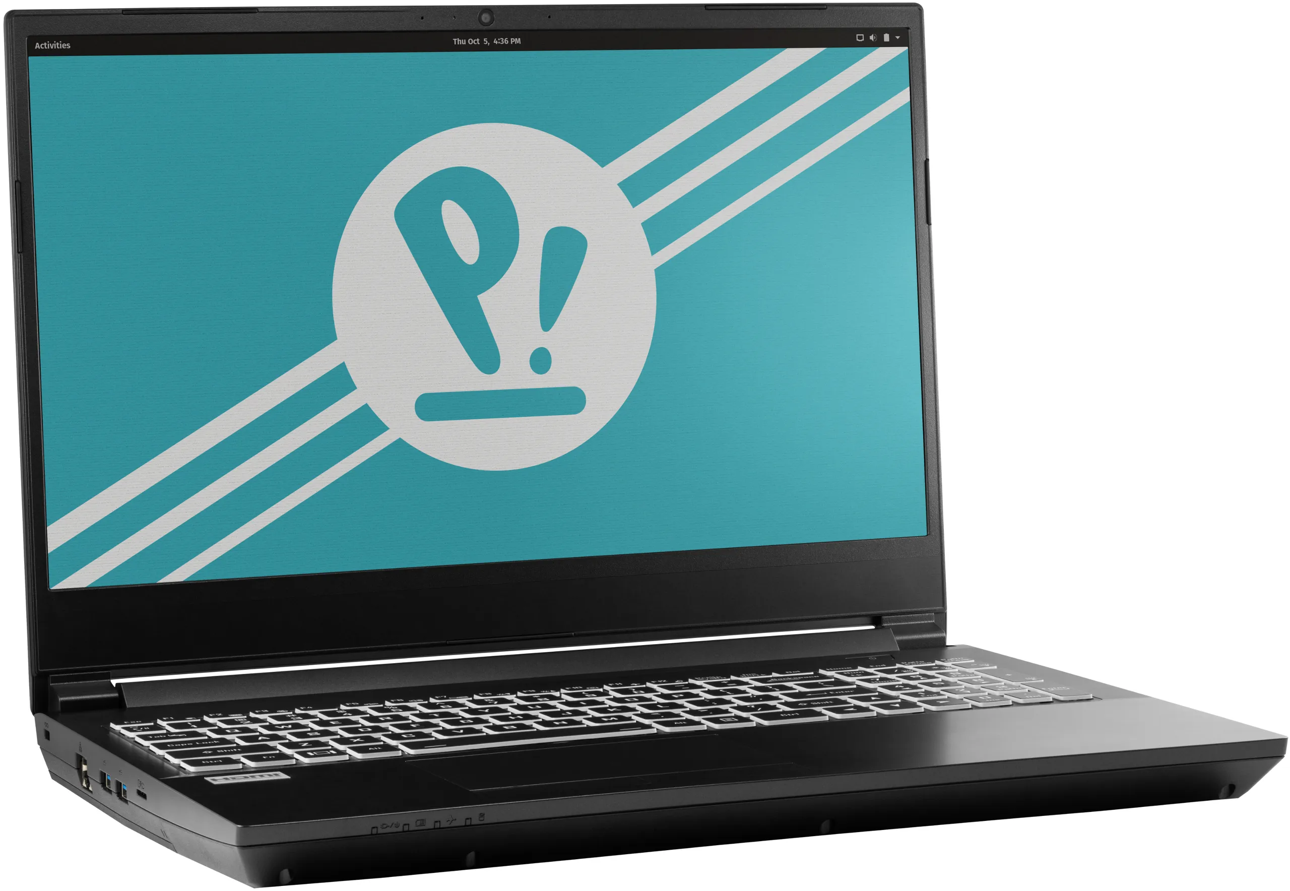
The System76 Serval WS is a laptop with the following specifications:
- CPU
- Supports AMD Ryzen (3rd Gen) CPUs
- Chipset
- AMD B450
- BIOS
- MX25U12872F flash chip
- SOIC-8 form factor
- Programmed with System76 firmware (non-open)
- MX25U12872F flash chip
- EC
- ITE IT5570E
- Programmed with non-open EC firmware
- Graphics
- GPU options:
- NVIDIA GeForce RTX 2070
- NVIDIA GeForce GTX 1660 Ti
- eDP display: 15.6" 1920x1080@144Hz LCD
- LCD panel options:
- Panda LM156LF-2F01
- LG P156WFG-SPB2
- or other equivalent
- LCD panel options:
- External video outputs:
- 1x HDMI
- 1x Mini DisplayPort 1.4
- 1x DisplayPort 1.4 over USB-C
- GPU options:
- Memory
- Up to 64GB (2x32GB) dual-channel DDR4 SO-DIMMs @ 3200 MHz
- Networking
- Gigabit Ethernet
- M.2 PCIe/CNVi WiFi/Bluetooth
- Intel Wi-Fi 6 AX200/AX201
- Power
- RTX 2070:
- 230W (19.5V, 11.8A) DC-in port
- Barrel size: 5.5mm (outer), 2.5mm (inner)
- Included AC adapter: Chicony A17-230P1A
- AC power cord type: IEC C13
- 230W (19.5V, 11.8A) DC-in port
- GTX 1660 Ti:
- 180W (19.5V, 9.23A) DC-in port
- Barrel size: 5.5mm (outer), 2.5mm (inner)
- Included AC adapter: Chicony A17-180P4A
- AC power cord type: IEC C5
- 180W (19.5V, 9.23A) DC-in port
- 62Wh 6-cell Lithium-Ion battery
- Model number: PB50BAT-6
- RTX 2070:
- Sound
- Internal speakers & microphone
- Combined headphone & microphone 3.5mm jack
- Microphone 3.5mm jack
- HDMI, Mini DisplayPort, USB-C DisplayPort audio
- Storage
- M.2 SSD (slot 1): PCIe NVMe Gen 2
- M.2 SSD (slot 2): PCIe NVMe Gen 3 or SATA III
- 1x 2.5" 7mm (SATA)
- MicroSD card reader
- USB
- 2x USB 3.2 Gen 2 Type-A
- 1x USB 3.2 Gen 2 Type-C
- 1x USB 2.0 Type-A
- Dimensions
- 3.251cm x 36.0934cm x 25.806cm, 2.70kg
Serval WS (External Overview)
Left side overview:

Right side overview:

Front side overview:

Back side overview:

Keyboard Shortcuts
The Serval WS has the following actions available using the Fn and Function keys:
| Key | Shortcut | Action |
|---|---|---|
 | Fn+F1 | Toggle trackpad |
 | Fn+F2 | Toggle built-in LCD |
 | Fn+F3 | Mute |
 | Fn+F5 | Volume down |
 | Fn+F6 | Volume up |
 | Fn+F7 | Toggle displays |
 | Fn+F8 | Screen brightness down |
 | Fn+F9 | Screen brightness up |
 | Fn+F10 | Toggle webcam |
 | Fn+F11 | Toggle airplane mode |
 | Fn+F12 | Suspend |
 | Fn+` | Play/Pause |
| 1 | Fn+1 | Toggle fan between max/automatic |
 | Fn+* | Toggle keyboard backlight |
| / (numpad) | Fn+/ | Cycle keyboard color |
| - (numpad) | Fn+- | Decrease keyboard brightness |
| + (numpad) | Fn++ | Increase keyboard brightness |
LED indicators
The Serval WS has the following LED indicators:
| Icon | Color | Description |
|---|---|---|
 | Orange | Powered off, DC power plugged in |
| Green | Powered on | |
| Blinking green | Sleeping (suspended) | |
 | Orange | Battery charging |
| Green | Battery fully charged | |
| Blinking orange | Battery critically low | |
 | Green | Airplane mode is on (WiFi/Bluetooth disabled) |
 | Green | Storage drive activity |
Serval WS (Internal Overview)
Bottom components and connectors:

- Fan/heatsink module is highlighted in white
- Additional fan is highlighted in olive
- Fan connectors are highlighted in pink
- M.2 SSDs are highlighted in yellow
- Wireless card is below the top M.2 SSD, highlighted dashed red
- CMOS battery connector is highlighted in cyan
- RAM is highlighted in light green
- 2.5" drive bay is highlighted in dark red
- Battery slot is highlighted in orange
- BIOS flash chip (U47), not highlighted
Under-keyboard components and connectors:

- Keyboard connector is highlighted in yellow
- Keyboard backlight connector is highlighted in green
- Power button/LED connector is highlighted in red
Serval WS (Parts & Repairs)
Many components in your Serval WS can be upgraded or replaced as necessary. Follow these step-by-step guides for instructions:
- Removing the battery
- Removing the bottom cover
- Replacing the keyboard
- Replacing the RAM
- Replacing an M.2/NVMe SSD
- Replacing the fans/heatsink/thermal paste
- Replacing the CPU
- Replacing the CMOS battery
- Replacing the WiFi/Bluetooth module
Removing the battery:
The battery provides primary power whenever the system is unplugged.
The model number for the Serval 12's battery is PB50BAT-6, and the original part number is 6-87-PB50S-61D02. Third-party battery sellers may list one or both of these numbers, and may offer other compatible part numbers with the same model number. You can also contact System76 to purchase a replacement battery.
Tools required: Cross-head (Phillips) screwdriver
Time estimate: 1 minute
Difficulty: Easy ●
Steps to remove the battery:
- Place the machine lid-side down.
- Use a soft surface (such as a towel) to avoid scratches.
- Unscrew the two battery screws (highlighted yellow below.)

- Pick the battery up and remove it from the slot.
Removing the bottom cover:
Removing the cover is required to access the internal components. Prior to removing the cover, ensure the AC power is unplugged and all peripherals (including SD cards and USB drives) are unplugged or removed from the system.
Tools required: Cross-head (Phillips) screwdriver
Time estimate: 5 minutes
Difficulty: Easy ●
Steps to remove the bottom cover:
- Remove the battery.
- Remove the 5 bottom panel screws (highlighted red below.)

- Slide the bottom panel away from the battery slot, then lift it off of the case.
Replacing the keyboard:
The keyboard can be replaced using the instructions below.
Tools required: Cross-head (Phillips) screwdriver
Time estimate: 10 minutes
Difficulty: Medium ●
Steps to replace the keyboard:
- Follow the steps above to remove the battery and remove the bottom cover.
- Remove the two keyboard screws (circled green and cyan below.)

- Open the lid slightly and place the machine on its side.
- Push the screwdriver into the keyboard push point (highlighted cyan above) until the keyboard pops out.

- Flip the keyboard over onto the touchpad and set the Serval WS back down. The larger ribbon cable is for the keyboard, while the smaller ribbon cable is for the keyboard backlight.

- Flip the black latches (highlighted red below) upwards to free the ribbon cables.

- Pull the ribbon cables out of the connectors.
- Remove the keyboard and replace it with the new one.
- Carefully slide both ribbon cables into their connectors.
- Flip the black latches back into place to secure the ribbon cables.
- Place the keyboard back into position, starting with the tabs on the bottom edge.
- Secure the rest of the keyboard by pressing down on each of its edges.
- Turn the machine lid-side down again.
- Replace the 2 keyboard screws, the bottom panel, and the battery.
- Boot the machine and confirm the keyboard and keyboard backlight are operational.
Replacing the RAM:
The Serval WS 12 supports up to 64GB (2x32GB) of DDR4 SO-DIMMs running at 3200MHz. If you've purchased new RAM, need to replace your RAM, or are reseating your RAM, follow these steps.
Tools required: Cross-head (Phillips) screwdriver
Time estimate: 10 minutes
Difficulty: Easy ●
Steps to replace the RAM:
- Follow the steps above to remove the battery and remove the bottom cover.
- Press the small tabs on both sides of the RAM simultaneously. The RAM should spring up to an angle.

- Remove the RAM from the slot.
- Insert the new RAM (or reseat the existing RAM) by placing it in the keyed slot and pressing down on the RAM until it clicks into place.
Replacing an M.2/NVMe SSD:
This model supports up to two M.2 SSDs. Both M.2 slots are size 2280. Slot 1 supports PCIe NVMe Generation 2, while Slot 2 supports either SATA III or PCIe NVMe Generation 3.
Tools required: Cross-head (Phillips) screwdriver
Time estimate: 10 minutes
Difficulty: Easy ●
Steps to replace the M.2 drive:
- Follow the steps above to remove the battery and remove the bottom cover.
- Unscrew the retainer screw opposite the M.2 slot.

- Remove the existing M.2 drive by pulling it out of the slot.
- Insert the new M.2 drive into the slot and hold it in place.
- The slot closest to the fan supports either PCIe NVMe Generation 3 or SATA III. The slot closest to the battery supports PCIe NVMe Generation 2 only. (PCIe NVMe Generation 3 drives will work at slower speeds in the Generation 2 slot.)
- Replace the retainer screw.
Replacing the cooling system:
The Serval WS 12 has a single heatsink for the CPU and GPU. One fan is attached to the heatsink, while one additional fan is separate from the heatsink.
If the fans become noisy and cleaning them out doesn't fix the issue, you may need a new fan. Contact Support to start a warranty claim or parts purchase.
Depending on your climate and the age of the machine, it may be necessary to apply new thermal paste between the CPU/GPU and the heatsink. Thermal paste helps facilitate effective heat transfer between the CPU/GPU and the cooling equipment. These instructions can also be used in the unlikely event your heatsink needs replacing.
Tools required: Cross-head (Phillips) screwdriver
Time estimate: 15 minutes
Difficulty: High ●
Steps to replace the heatsink/thermal paste:
- Follow the steps above to remove the battery and remove the bottom cover.
- Locate the CPU heatsink screws.
- Remove the eight numbered screws in reverse order, starting with #8, then #7, and continuing until you have removed #1. Screws 1-6 (highlighted red below) are on the heat sink, while 7-8 (highlighted green below) are on the attached fan.

- Unplug the white fan connector (for the attached fan) from the motherboard.
- Remove the heatsink/fans from the case, being careful not to bend the heatsink pipes. It may take some pressure to break the seal of the thermal paste. If necessary, apply pressure using a flat object wedged underneath the ends of the heatsink pipes.
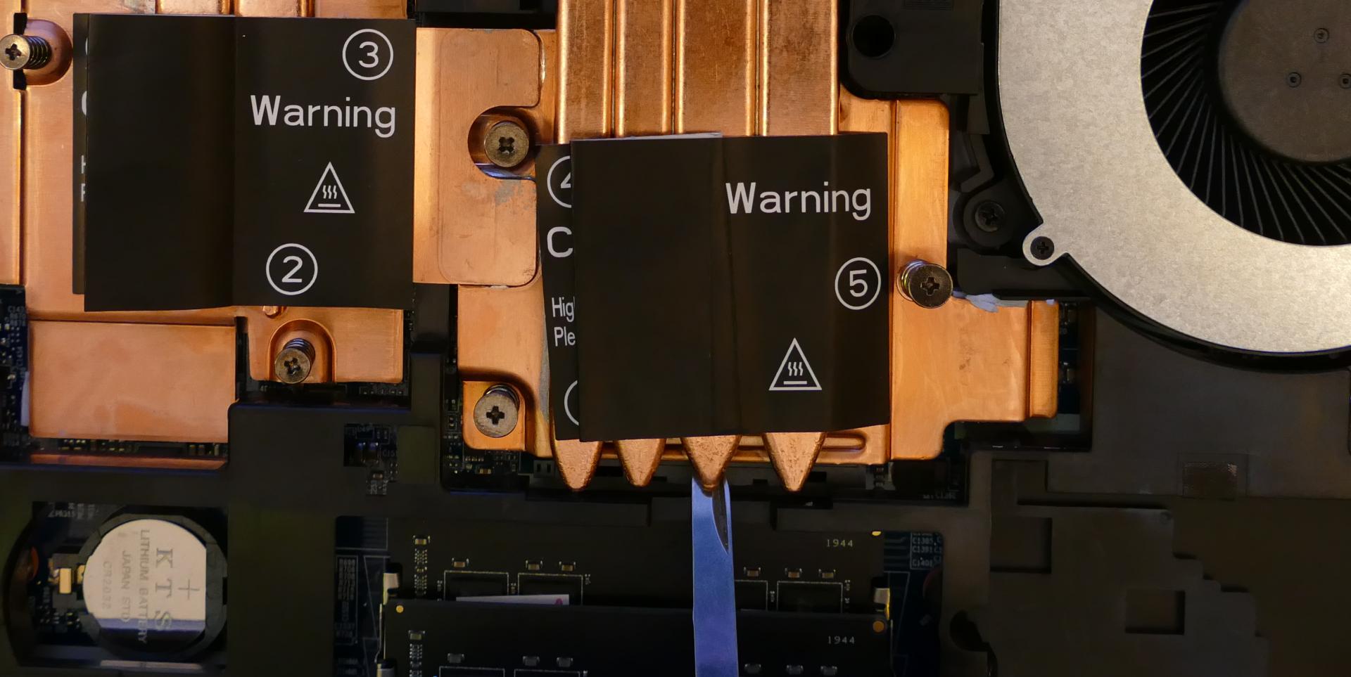
- Using a paper towel, remove the existing thermal paste. You may also use a small amount of rubbing alcohol if the old paste is dried or difficult to remove.


- After cleaning the CPU, GPU, and heatsink, apply a small line of thermal paste directly onto the CPU and GPU chips.

- Carefully replace the heatsink.
- Replace the heatsink and fan screws, starting with #1, then #2, and so on until #8.
- Plug the white fan connector (for the attached fan) back into the motherboard.
Steps to replace the additional fan:
- Follow the steps above to remove the heatsink.
- Remove the three screws (highlighted yellow in the above section) holding the additional fan in place.
- Unplug the black connector from the motherboard (pictured below) and remove the additional fan.

Replacing the CPU:
The Serval WS uses an AM4 socket for the CPU. If you are upgrading or replacing your CPU, follow the steps below.
Tools required: Cross-head (Phillips) screwdriver
Time estimate: 20 minutes
Difficulty: High ●
Steps to replace the CPU:
- Follow the steps above to remove the battery, remove the bottom cover, and remove the heatsink.
- Lift up the lever holding the CPU in place, highlighted red below.
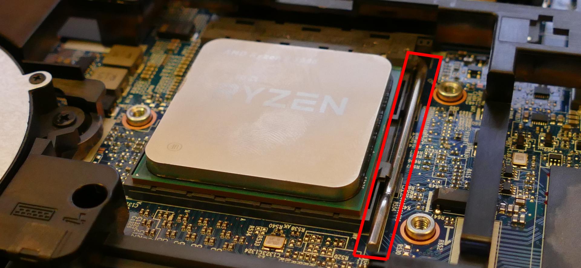
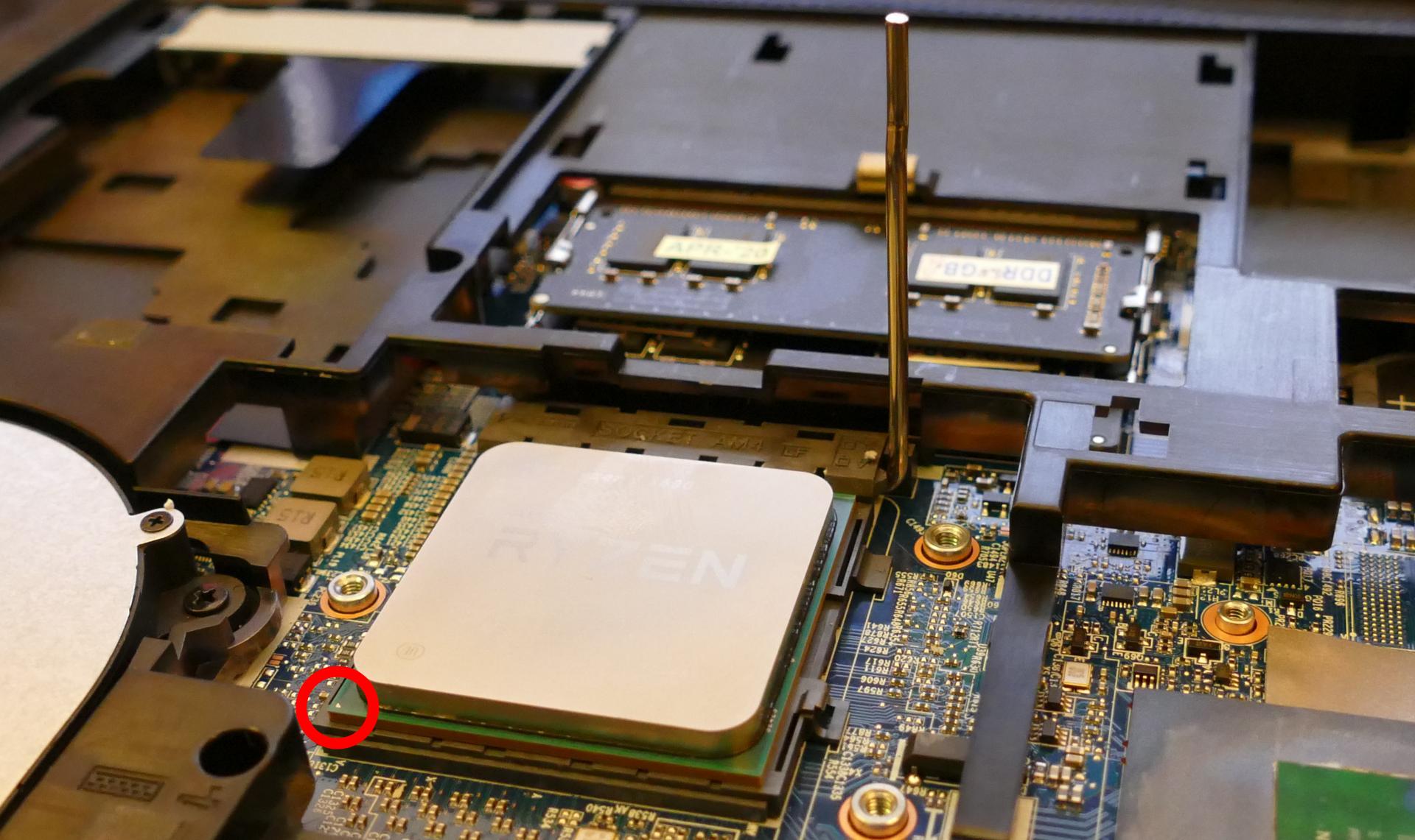
- Carefully lift the old CPU out of the socket. Caution: Be careful not to bend any of the gold pins on the bottom of the CPU.
- Carefully place the new CPU into the socket. One of the corners of the socket and CPU are marked with a triangle; be sure to match the triangles to the same corner so the CPU is placed in the correct orientation.
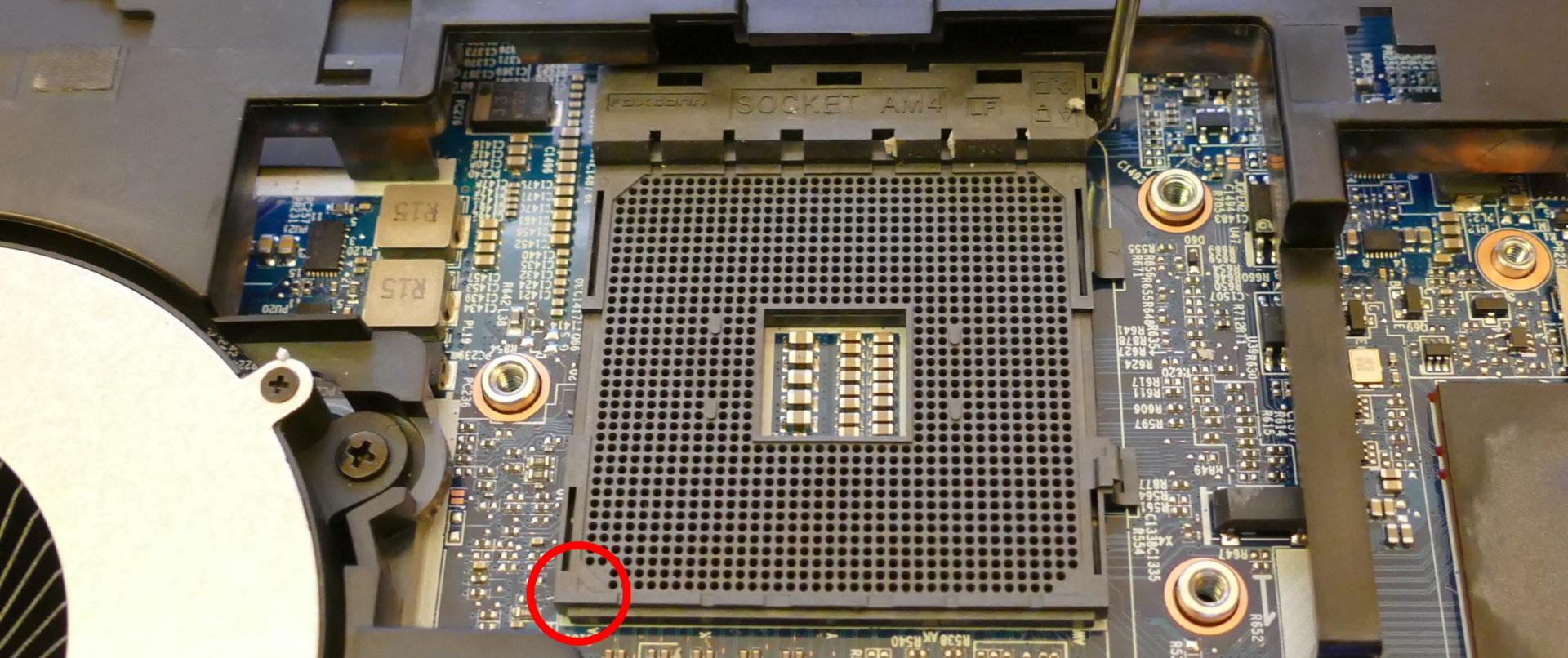
- Replace the thermal paste, heatsink/fan(s), bottom panel, and battery.
Replacing the CMOS battery:
The CMOS battery supplies power to the system's CMOS chip. UEFI settings and the comptuer's hardware clock are stored on the CMOS. If your system doesn't boot, you can reset the CMOS to force a low-level hardware reset. If your clock is constantly resetting, it's likely your CMOS battery needs to be replaced.
Warning (ingestion hazard): Keep batteries out of reach of children. Death or serious injury can occur if ingested. If a battery is suspected to be swallowed or inserted inside any part of the body, seek immediate medical attention. In the US, you can also call the National Battery Ingestion Hotline for guidance: 1 (800) 498-8666
Tools required: Cross-head (Phillips) screwdriver
Time estimate: 10 minutes
Difficulty: Easy ●
Steps to replace the CMOS battery:
- Follow the steps above to remove the main battery and remove the bottom cover.
- Locate the CMOS battery, which is in between the M.2 SSD slots and the RAM slots, just next to the battery slot.

- From the side of the battery that is not covered, pull the battery up to free it from the slot, then remove it.
- To clear the CMOS, open the lid of the machine and hold down the power button for at least 15 seconds to discharge any residual energy in the system.
- Place the new (or existing) CMOS battery in the black plastic slot, starting with the side that will cover the battery, then push the opposite side back into place.
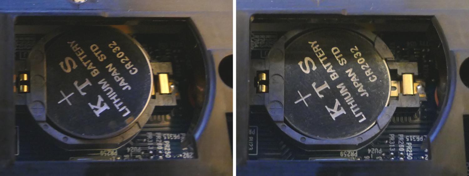
- Replace the bottom panel and main battery.
- Power up the Serval WS. The system may power itself off and on after initial boot; this is normal behavior when the CMOS has been reset.
Replacing the wireless card:
Your Serval WS's WiFi and Bluetooth are both handled by the same module. It is a standard M.2 2230 slot with PCIe and USB interfaces (E-key).
Tools required: Cross-head (Phillips) screwdriver
Time estimate: 10 minutes
Difficulty: Medium ●
Steps to replace the WiFi/Bluetooth module:
- Follow the steps above to remove the battery and remove the bottom cover.
- If there is an M.2 SSD in the slot closest to the fan/heatsink, follow the steps above to remove the M.2 SSD.
- Locate the wireless module. Remove any clear tape that is securing the wires.

- Gently remove the two antennas (highlighted red above) by pulling them up and away from the wireless card.
- Remove the retaining screw opposite the M.2 slot, highlighted yellow above.
- The wireless card will pop up at an angle. Remove the card from the M.2 slot.
- Insert the new wireless card into the M.2 slot at an angle.
- Replace the retaining screw.
- Attach the two antennas by aligning the circular fittings and pressing onto the wireless card. The connectors will snap into place. Use caution when attaching the connectors; the pins can bend, break, or snap.
- Replace the M.2 SSD, bottom cover, and battery.
Thelio (thelio-r3-n1)
The System76 Thelio is a desktop with the following specifications:
- Processor options
- Supports AMD Ryzen 7000 series (Zen 4) CPUs
- Motherboard
- MSI MPG B650I Edge WiFi running System76 Firmware (non-open)
- AMD B650 chipset
- Daughterboard
- Thelio Io board running open-source firmware
- Revision 2
- Thelio Io board running open-source firmware
- Graphics options
- One GPU (PCIe 4.0 x16) of up to two-slot height
- GPU size:
- Internal clearance: 278.175mm
- Recommended maximum length: 268.175mm
- Tested with the following GPUs:
- Integrated Graphics
- 1x HDMI 2.1
- AMD Radeon RX 7600
- 1x HDMI 2.1, 3x DisplayPort 2.1
- NVIDIA GeForce RTX 4060 Ti
- 1x HDMI 2.1a, 3x DisplayPort 1.4a
- NVIDIA GeForce RTX 4070
- 1x HDMI 2.1, 3x DisplayPort 1.4a
- Integrated Graphics
- Expansion
- 1x PCIe 4.0 x16 (GPU slot)
- Memory
- Tested with up to 64GB (2x32GB) dual-channel DDR5 DIMMs @ 4800 MHz
- Motherboard supports up to 128GB (2x64GB) @ 7200+ MHz w/ overclocking (not tested)
- Tested with the following RAM modules (may ship with other tested modules):
- Crucial CT32G48C40U5 (32GB/stick)
- Tested with up to 64GB (2x32GB) dual-channel DDR5 DIMMs @ 4800 MHz
- Networking
- 1x 2.5-Gigabit Ethernet (Realtek RTL8125BG)
- Wi-Fi 6E + Bluetooth 5.2 (Mediatek MT7921K)
- Power
- C13 power cord
- 650W PSU
- Tested with the following PSU models (may ship with other tested models):
- Sound
- Back: 3.5mm line out, line in, microphone jacks
- Front: 3.5mm line out, microphone jacks
- Up to 7.1-channel audio output
- Realtek ALC4080 audio chipset
- HDMI, DisplayPort audio (depending on GPU)
- Storage
- 2x M.2 (PCIe NVMe Gen 4) SSD
- 2x 2.5" SATA
- USB
- 1x USB 3.2 Gen 2x2 Type-C
- Back port
- 1x USB 3.2 Gen 2 Type-C
- Top port
- 3x USB 3.2 Gen 2 Type-A
- Back ports
- 3x USB 3.2 Gen 1 Type-A
- 2x back ports, 1x top port
- 1x USB 3.2 Gen 2x2 Type-C
- Dimensions
- 32.7cm × 20.7cm × 29.1cm
Thelio (External Overview)
Back overview:

Power Switch Guide:
- 1: On
- 0: Off
Other notes:
- The
Flash BIOSbutton is not needed when performing UEFI firmware updates via the System76 Firmware Manager. Use of theFlash BIOSbutton is not recommended.
Front/side overview:

Top/bottom overview:

Thelio (Internal Overview)
Left side overview:
Chassis components:

- CPU duct is highlighted in red
- Side brace is highlighted in green
Electronic components:

- CPU heatsink is highlighted in yellow
- RAM slots are highlighted in green
- M.2 slot 1 heatsink is highlighted in cyan
- GPU slot (PCIe 4.0 x16 slot) is highlighted in red
- Power supply is highlighted in pink
- Bottom case fan is highlighted in orange
- Thelio Io daughterboard is highlighted in white
Right side overview:

- M.2 slot 2 is highlighted in cyan
- CPU fan Y-cable connector is highlighted in yellow
Front side overview:

- Internal power button (on the Thelio Io board) is highlighted in green
Top overview:

- 2.5" drive screws are highlighted in green
- 2.5" drive cage cover is highlighted in cyan
- Top I/O board is highlighted in white
- Connects to motherboard
- Motherboard CPU fan header is highlighted in yellow
- Connects to Thelio-IO board
- CPU power connector is highlighted in red
- Connects to power supply
- CPU fan splitter is highlighted in pink
- Connects to Thelio Io board and CPU fans
- Power button receptacle is highlighted in orange
Thelio (Parts & Repairs)
Many components in your Thelio can be upgraded or replaced as necessary. This page uses photos of the R3-N1 revision, which indicates:
- R3: The third AMD motherboard used in Thelio (base size).
- N1: Based on the first revision of the nebula19 chassis.
Minor case details may vary based on the production date of the unit, but screw counts, general component locations, and other details should remain the same unless otherwise noted.
Power the machine off, switch off the power supply, and unplug all peripherals before working with any internal components. Then, follow these step-by-step guides for instructions:
- Replacing the front accent strip
- Removing the top case
- Adding/removing 2.5" storage drives
- Removing the side brace
- Replacing the bottom case fan
- Replacing the GPU
- Removing the CPU duct
- Replacing the RAM
- Replacing the M.2 drives
- Replacing the CPU fans
- Replacing the CPU cooler/thermal paste and CPU
- Replacing the power supply
- Replacing the Thelio Io board
- Replacing the SATA backplane
- Replacing the top I/O
- Troubleshooting the power button
Replacing the front accent strip:
Thelio includes a customizable accent panel on the front of the case, which can be swapped to change the case's look and feel. The instructions for swapping the accent are also available in video form.
Tools required: None
Time estimate: 30 seconds
Difficulty: Easy ●
Steps to replace the front accent strip:
- Place the Thelio on the edge of the desk so the front side is hanging off of the desk.
- The Thelio can alternatively be lifted or tilted so the front of the computer is hovering above the desk.
- Slide the accent strip down to unlock it.
- The accent can be gripped at the bottom edge.
- Pull the accent strip off of the case, starting with the bottom edge.
- Place the new accent strip onto the front of the case and slide it up to lock it into place.

Removing the top case:
The top case can be removed to access the internal components.
Tools required: Cross-head (Phillips) screwdriver (optional)
Time estimate: 1 minute
Difficulty: Easy ●
Steps to remove the top case:
- Remove the four outer screws holding the top case onto the machine.

- Slide the top case up and off of the machine.
Adding/removing 2.5" storage drives:
Thelio R3-N1 supports up to two 2.5" SATA III drives.
Tools required: Cross-head (Phillips) screwdriver (optional)
Time estimate: 5 minutes
Difficulty: Easy ●
Steps to add/remove 2.5" storage drives:
- Follow the steps above to remove the top case.
- Unscrew the two screws securing the drive bay's cover, highlighted green below.

- If you are adding a new drive, pop out the black plastic ring on the top crossbar and slide out four screws (per drive).
- Insert four screws into each 2.5" storage drive you wish to install.
- Slide each 2.5" drive into one of the slots leading to the Thelio-IO board.


Thelio R3-N1 with one 2.5" screw ring removed and one 2.5" drive installed.
- Replace the black plastic screw ring and the 2.5" drive bay cover.
Removing the side brace:
The side brace provides a mounting point for the GPU brace finger, which helps keep GPUs or other PCI Express cards in place during shipping. It also provides mounting points for one 120mm fan, which is not offered as part of Thelio but can optionally be installed as an aftermarket upgrade.
The GPU brace finger is only required during shipping. The system can be run without this part if it does not fit an upgraded GPU.
Tools required: Cross-head (Phillips) screwdriver
Time estimate: 15 minutes
Difficulty: Easy ●
Steps to remove the side brace:
- Follow the steps above to remove the top case.
- Unscrew the four screws holding the side bracket in place (two on the front of the case, two on the back.)

- Pull the side brace out of the chassis. Unplug the side fan connector from the splitter board on the right side, if connected.
Steps to adjust the GPU brace finger:
- Follow the steps above to remove the top case and remove the side brace.
- To adjust the GPU brace finger's horizontal position, unscrew the four corner screws (highlighted green below), move the GPU brace finger's mounting bar, and reattach it in the desired position.
- The center vertical adjustment screw (highlighted cyan below) may also need to be removed or loosened.

- To adjust the GPU brace finger's vertical position, unscrew the eight vertical adjustment screws (four on either side), move the GPU brace finger, and reattach it in the desired position.
- There may be one or two rows of screw holes on the mounting bar, depending on what GPU your system originally shipped with. The additional row of screw holes allows front-to-back adjustment of the GPU brace fingers' position.

Replacing the bottom case fan:
Thelio R3-N1 has one case-mounted 140mm intake fan on the bottom of the chassis.
Part numbers:
- The bottom case fan is a Be Quiet! Silent Wings 4 (
BQ SIW4-14025-MF-PWM).
Tools required: Cross-head (Phillips) screwdriver
Time estimate: 20 minutes
Difficulty: Medium ●
Steps to replace the bottom case fan:
- Follow the steps above to remove the top case.
- The side brace can optionally be removed to provide easier access to the fan and its cabling. In the below photos, the GPU has also been removed for greater visibility.
- Unplug the fan's cable from the Thelio Io daughterboard.
- The bottom case fan plugs into the
FANOUT2port, also known as theINTAKE FANport, on the Thelio Io board. - When viewed from interior of the chassis, this connector is on the bottom-left.
- The bottom case fan plugs into the

- Unscrew the four fan screws from the bottom of the machine.
- To avoid damaging other components, place the machine on its front side when working with the bottom surface.

- Remove the old fan from the case.
- When installing the fan, mount the components in the following order:
- Chassis
- Dust filter
- Acrylic spacer
- Fan
- The new fan's cable should be oriented towards the front-interior corner of the case. The cable is not routed through any case holes or Velcro loops by default. The cable runs back towards the power supply, then folds over and runs to the front of the case to the Thelio Io board.
Replacing the GPU:
Thelio supports one dual-slot dedicated GPU. The GPU slot is a PCIe 4.0 x16 slot.
Tools required: Cross-head (Phillips) screwdriver
Time estimate: 10 minutes
Difficulty: Medium ●
Steps to replace the GPU:
- Follow the steps above to remove the top case and remove the side brace.
- If you're removing a GPU, unplug the GPU power cable from the right side of the card. Hold down the latch on the connector while unplugging the cable.

- Unscrew the two back screws holding the PCIe bracket in place, and remove the PCIe bracket.
- The bracket must be completely removed because simply sliding it over doesn't provide enough clearance for GPU installation/removal.

- Push and hold the latch on the motherboard to free the PCIe connection, then pull the card out of the slot.
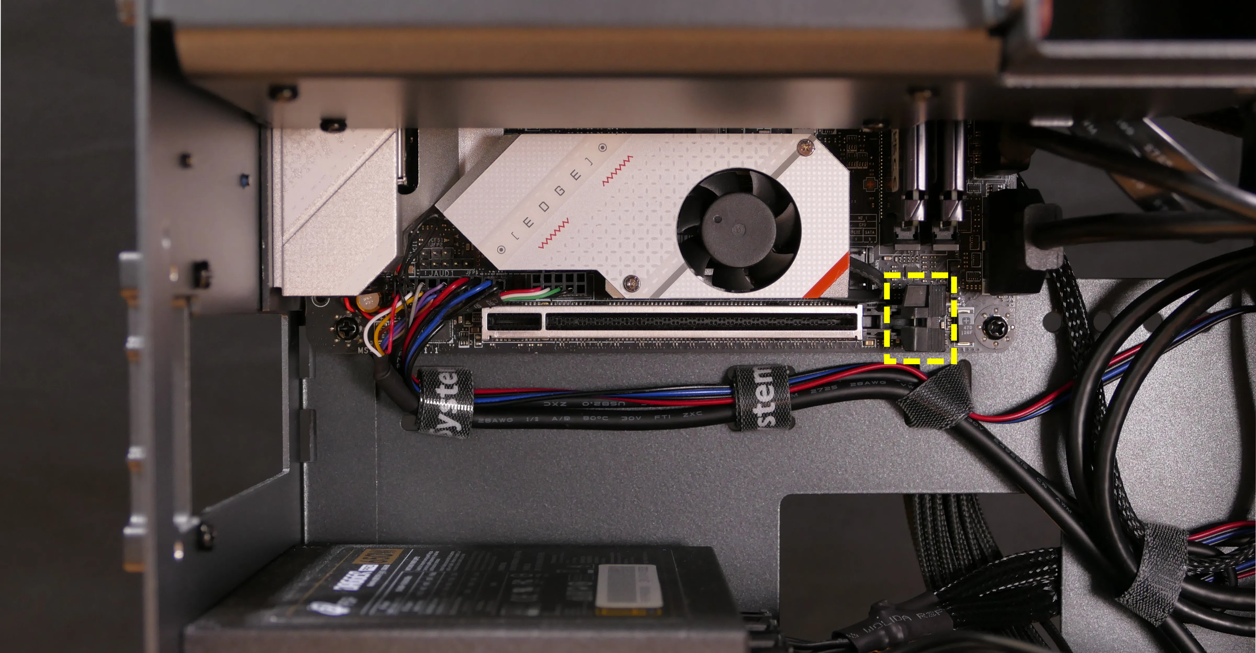
- After inserting the new GPU into its slot, connect the power cable.
- Once the GPU is installed, replace the back PCIe bracket, side brace, and top case.
Removing the CPU duct:
The CPU duct guides airflow through the CPU cooler. It covers the CPU and partially obstructs the RAM slots and top GPU.
Tools required: Cross-head (Phillips) screwdriver
Time estimate: 7 minutes
Difficulty: Easy ●
Steps to remove the CPU duct:
- Follow the steps above to remove the top case.
- Unplug both CPU fan connectors from the splitter board in the top corner of the machine.
- The splitter board provides the same signal to both ports, so it doesn't matter which fan is plugged into which port.

- Unscrew the four back thumbscrews and two top crossbar screws holding the CPU duct in place.


- Pull the CPU duct away from the machine.
Replacing the RAM:
Thelio R3-N1 supports up to 64GB (2x32GB) of RAM. The RAM sticks are DDR5 DIMMs (non-ECC) running at a speed of up to 4800MHz. If you've purchased new RAM, need to replace your RAM, or are reseating your RAM, follow these steps.
Tools required: Cross-head (Phillips) screwdriver
Time estimate: 15 minutes
Difficulty: Medium ●
Steps to replace the RAM:
- Follow the steps above to remove the top case and remove the CPU duct.
- The side brace does not need to be removed, but it's been removed in the below photo for better visibility.
- To remove an existing RAM stick, flip the top latch up away from the stick, then pull the stick out of the slot, starting from the top edge. (The bottom of the RAM slot does not move.)

- Make sure the tab on the top of the slot is open (pulled upwards), then insert the new RAM (or re-seat the existing RAM) into the slot, starting with the bottom edge.
- The RAM stick will only fit in one direction. The larger group of pins goes on top.
- If you are only using one RAM stick, place it in the right-side slot (farthest from the CPU.)
- Replace the top case.
Replacing the M.2 drives:
Thelio R3-N1 has two M.2 slots (M key). Both slots are size 2280 and support PCIe NVMe Generation 4.
Tools required: Cross-head (Phillips) screwdriver
Time estimate: 30 minutes
Difficulty: Medium ●
Steps to replace the M.2 drive (slot 1):
- Follow the steps above to remove the top case, remove the side brace, remove the GPU, and remove the CPU duct.
- Removing the CPU duct and GPU is optional but recommended to provide more working space and avoid damage.
- Unscrew and remove the M.2 heatsink.
- It may take some pressure to remove the heatsink and thermal tape from the M.2 drive. After unscrewing the heatsink, pull slowly to avoid breaking the thermal tape.
- The heatsink fan is connected to the motherboard. This connector does not need to be unplugged to access the M.2 slot.
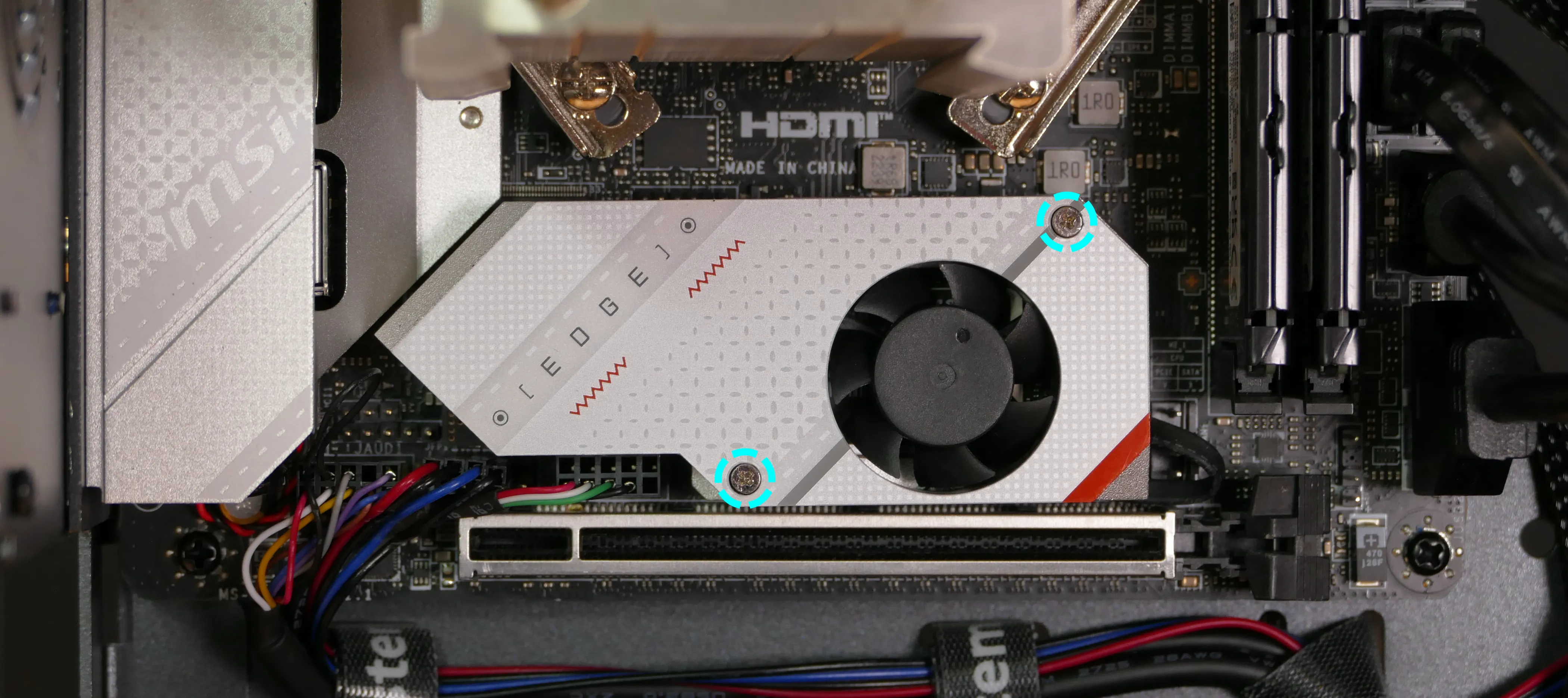
- Unscrew the retainer screw opposite the M.2 slot.
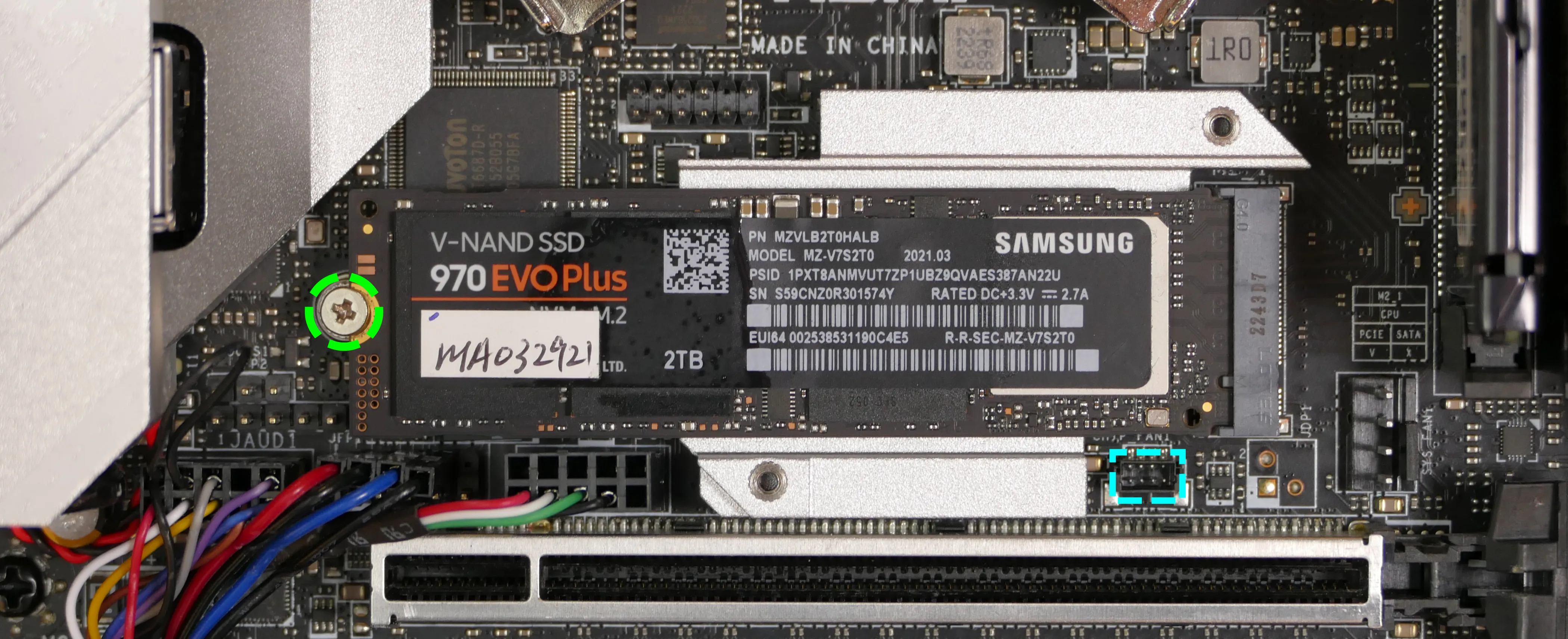
- Insert the new M.2 drive into the slot and hold it in place.
- Replace the retainer screw.
- Replace the M.2 heatsink, CPU duct, GPU, side brace, and top case.
- When replacing the M.2 heatsink, ensure its fan is plugged into the M.2 fan connector (highlighted cyan above).
Steps to replace the M.2 drive (slot 2):
- Follow the steps above to remove the top case.
- Unscrew the retainer screw opposite the M.2 slot.
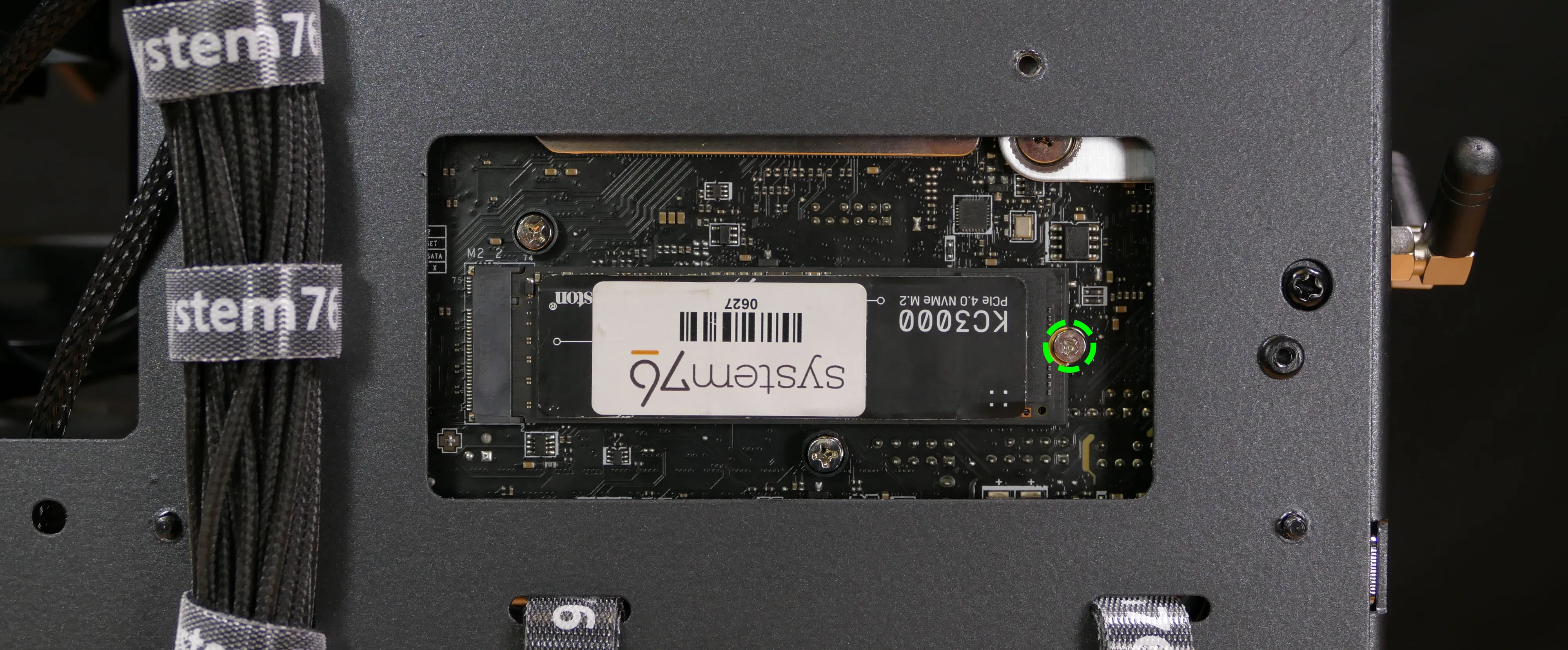
- Remove the existing M.2 drive by pulling it out of the slot.
- Insert the new M.2 drive into the slot and hold it in place.
- Replace the retainer screw.
Replacing the CPU fans:
Thelio R3-N1 contains two 92mm CPU fans, both mounted on the CPU duct.
Part numbers:
- The front fan is a Noctua
NF-A9 PWM. - The back fan is a Be Quiet! Pure Wings 2 (
BQ PUW2-9225-MR-PWM).
Tools required: Cross-head (Phillips) screwdriver
Time estimate: 25 minutes
Difficulty: Medium ●
Steps to replace the CPU fans:
- Follow the steps above to remove the top case and remove the CPU duct.
- Unscrew the four screws (two on each side) holding the fan bracket onto the duct.
- In the photos below, the front fan bracket's screws are highligted cyan, and the back fan bracket's screws are highlighted green.

- Unscrew the four screws holding the fan onto the fan bracket.
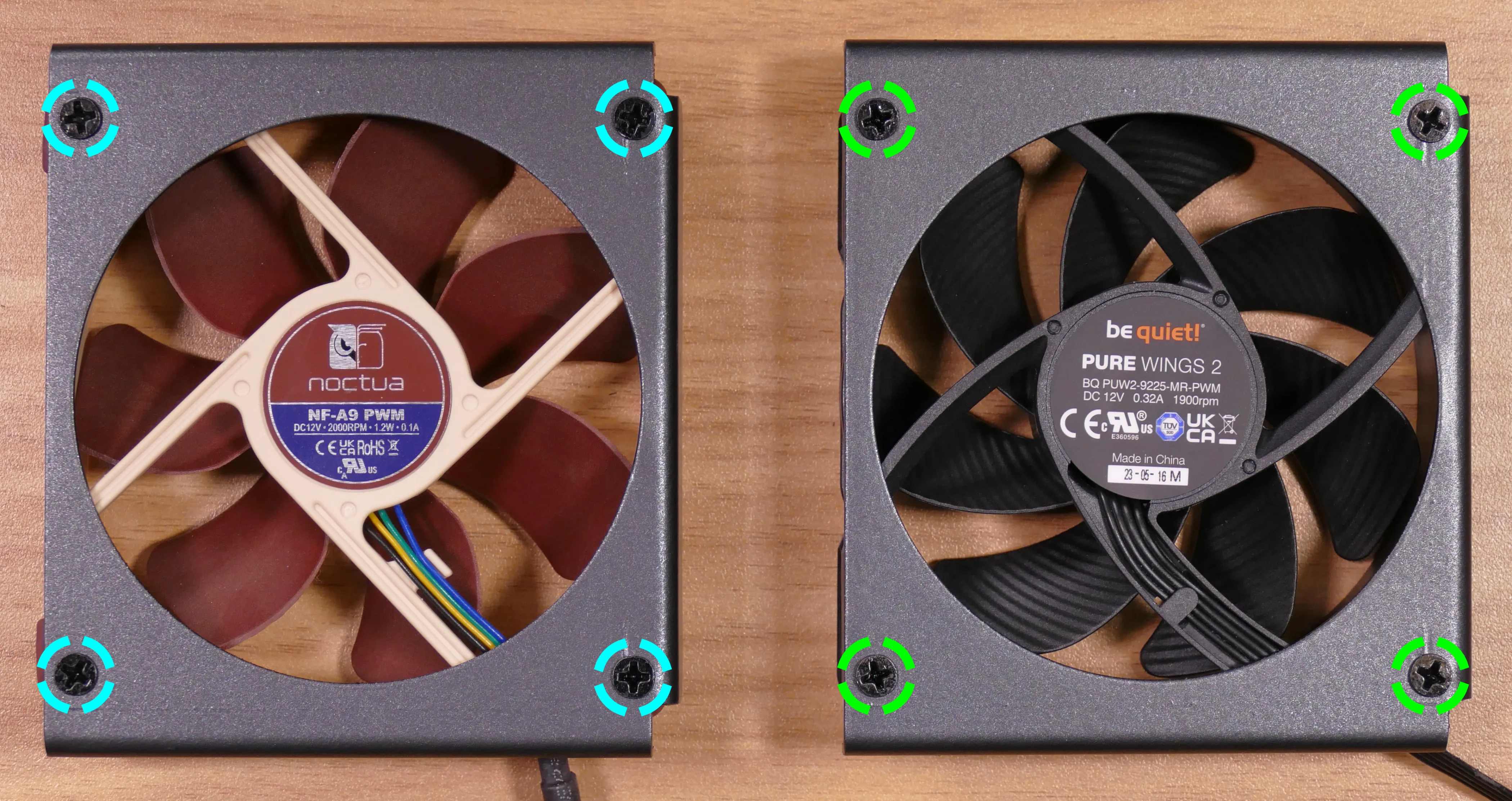
- When reinstalling the fan into the CPU duct, the spinning side should face towards the front of the case, and the cable should point towards the top corner of the open side of the duct.
- Overtightening a fan's screws may cause fan noise; if a fan is creating excessive noise, try slightly loosening some of the screws.
Replacing the CPU cooler and CPU:
The CPU cooler dissipates heat from the CPU to the heatsink, where the CPU fans expel it from the system. Depending on your climate and the age of the machine, replacing the thermal paste between the CPU and the cooler/heatsink may help the system run cooler.
Part numbers:
- The CPU cooler is a Noctua
NH-U9S. - The CPU uses an AMD AM5 socket.
Tools required: Cross-head (Phillips) screwdriver, thermal paste
Time estimate: 45 minutes
Difficulty: High ●
Steps to remove the CPU cooler/thermal paste:
- Follow the steps above to remove the top case, remove the side brace, remove the GPU, and remove the CPU duct.
- While holding the CPU cooler in place so it doesn't fall, unscrew the two screws holding the CPU cooler crossbar onto the vertical mounting brackets.
- The screws are held captive, and will not fully come out of the crossbar.
- Only the two outer screws need to be removed; the center screw holding the horizontal crossbar onto the heatsink does not need to be removed.

- The cooler will come away from the CPU.
- Using a paper towel, clean the existing thermal paste off of the heatsink and CPU. You may also use a small amount of rubbing alcohol if the old paste is dried or difficult to remove.

Steps to replace the CPU:
- Place the computer on its side so the motherboard is facing up.
- Unscrew and remove the cooler mounting bracket on the right side of the CPU.
- The grey plastic spacers over each mounting bracket screw hole do not need to be removed. If they fall off, put them back before reinstalling the mounting bracket.
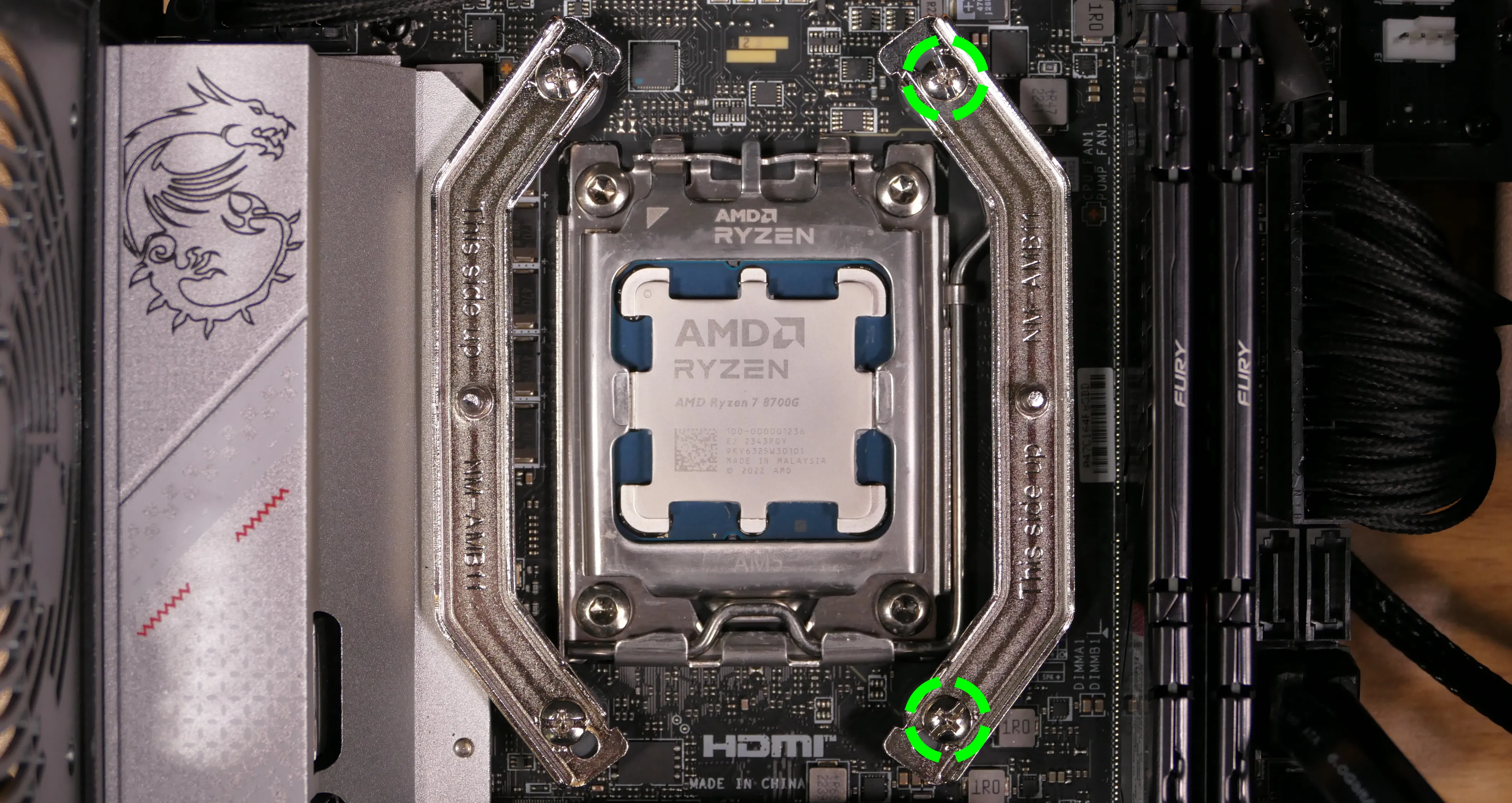
- Push the locking pin outward until it's able to spring away from the motherboard.
- Caution: the locking pin may spring up with significant force when freed.
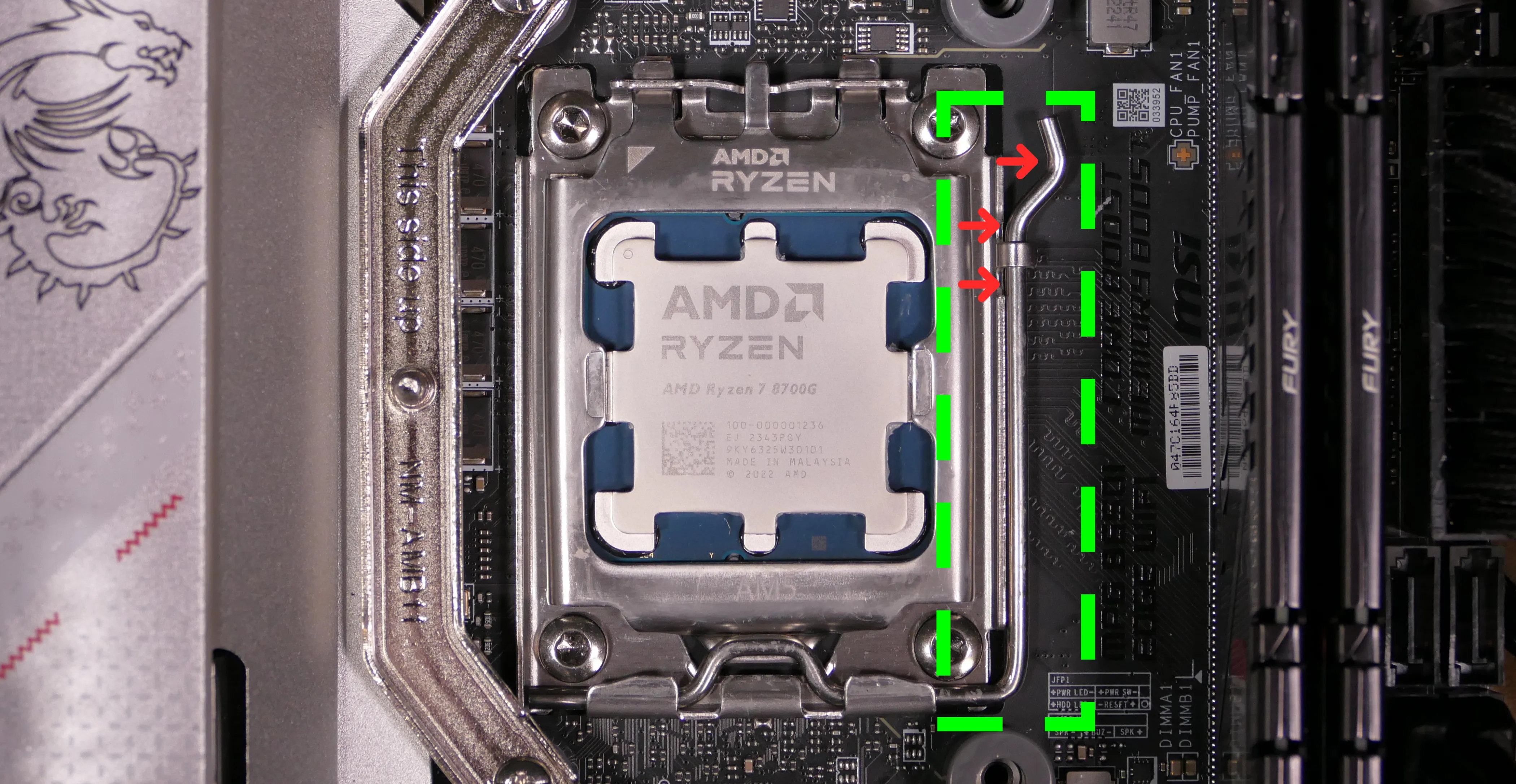
- Flip the CPU holder away from the CPU.
- The CPU holder opens in the opposite direction from the locking pin.

- Carefully lift the CPU out of the CPU socket.
- Be careful not to bend any of the gold pins on the CPU socket, and do not touch the gold pads on the CPU.

- Gently place the new CPU into the socket.
- When reinstalling the CPU, be sure to match the original orientation, with the triangle on the CPU pointing to the top left of the motherboard.
- The triangle on the CPU should match the triangle on the top of the CPU cover.
- Flip the CPU cover back onto the CPU and push the locking pin down into place.
- Reinstall the right-side cooler mounting bracket.
Steps to install the thermal paste/CPU cooler:
- Draw an
Xshape of thermal paste onto the CPU.

- Place the CPU cooler onto the CPU; while holding it in place, screw each end of the cooler crossbar onto one of the mounting brackets.
- The cooler should be oriented so the hole in the vertical center of the heatsink is facing the right side (front of the case).
- Insert each screw partially first, then fully tighten both.
- Set the computer upright, then reinstall the cooler-mounted CPU fan, CPU duct, GPU bracket, and top case.
Replacing the power supply:
The power supply unit (PSU) is modular and can be replaced with another unit of the same model. Different models may not be compatible with the cabling pre-installed in the Thelio.
Part numbers:
- The PSU is an FSP Dagger Pro 650W (
SDA2-650).
Tools required: Cross-head (Phillips) screwdriver
Time estimate: 20 minutes
Difficulty: Medium ●
Steps to replace the power supply:
- Follow the steps above to remove the top case, remove the side brace, and remove the GPU.
- Unplug all of the modular cabling from the back of the PSU.
- Some of the cables may be easier to unplug after the PSU has been unscrewed/removed from the case.

- Unscrew the four screws holding the PSU in from the back of the case.

- Remove/replace the PSU.
- The replacement PSU should be installed with the fan facing the bottom of the case.
- The PSU will need to be held up to the back of the case while it is screwed in.
- After screwing in the replacement PSU, use the labels and pin counts on the cables and ports to ensure the power cables are reconnected in the proper locations.
- Remember that not all of the available connectors will plug into the PSU-- the 8-pin (6 + 1) connector is to be plugged into the GPU.
Steps to clean the power supply dust filter:
- Follow the steps above to remove the power supply.
- Unscrew the four screws holding the dust filter onto the chassis.

- Remove the dust filter and clean it with compressed air, running water, or a damp cloth.
- When the filter is clean and dry, reinstall the filter, then reinstall the power supply and
Replacing the Thelio Io board:
Named after Jupiter's moon Io, the Thelio Io daughterboard handles the front power button and fan control. If the Thelio Io board becomes defective, it can be replaced using the instructions below.
Part numbers:
- Thelio R3-N1 uses Thelio Io version 2 (PCB revision thelio-io_2.3).
Tools required: Cross-head (Phillips) screwdriver
Time estimate: 25 minutes
Difficulty: High ●
Steps to replace the Thelio Io board:
- Follow the steps above to remove the top case.
- For easier access, it's also recommended to remove the side brace, remove the CPU duct, and remove the GPU.
- Unplug all cabling from the Thelio-IO board.
- The
POWER INPUT/POWER1connector requires pulling the white tab while unplugging.
- The

- Unscrew the two screws holding the daughterboard on from the front of the chassis.
- The plastic spacer behind the left screw will come off when the screw is removed. Hold it in place when screwing in the new board.

- Screw in the new Thelio Io board and reconnect the wiring.
Thelio Io wiring guide:

-
When wiring the Thelio Io board, refer to the port labels and the following guide.
FANOUT1/CPU FAN- to the CPU fan splitter.FANOUT4/AUX FAN- not connected.FANOUT2/INTAKE FAN- to the bottom case fan.FANOUT3/GPU FAN- to the side brace fan splitter (disconnected by default).FANIN1/MOTHERBOARD FAN INPUT- to theCPU_FAN1header at the top right of the motherboard, highlighted green below.

POWER1/POWER INPUT- to the power supply.- The white plastic backing needs to be held away from the connector to unplug this cable from the Thelio Io board.
PFP1/FRONT PANEL- to the power button receptacle on the front panel.- On the Thelio Io board, the wire color order (from top to bottom) is red, black, blue, black.
- On the power button receptacle, the wire color order (from left to right) is red, black, blue, black.
PMB1/MOTHERBOARD- to theJFP1header at the bottom left of the motherboard, highlighted cyan below.- On the Thelio Io board, the wire color order (from top to bottom) is red, black, blue, black.
- On the motherboard, the wire color order (from left to right) is red, black, blue, black.
USB- to theUSB_3_4header at the bottom left of the motherboard, highlighted yellow below.- A small clip needs to be held down to unplug this cable from the Thelio Io board.
- This port can alternatively be connected to the
USB_5_6header if theUSB_3_4header is connected to the wireless card.

Replacing the SATA backplane:
The SATA backplane provides two 2.5" SATA data and power connectors for the 2.5" drive cage.
Part numbers:
- The part number and version for the SATA backplane is thelio-io-sata_2.2.
Tools required: Cross-head (Phillips) screwdriver
Time estimate: 30 minutes
Difficulty: Medium ●
Steps to replace the SATA backplane:
- Follow the steps above to remove the top case, then remove the 2.5" drive cage cover and all 2.5" SATA drives.
- Use the cutout on the front right corner of the chassis to unplug the 4-pin Berg power connector and the two SATA data cables from the SATA backplane.
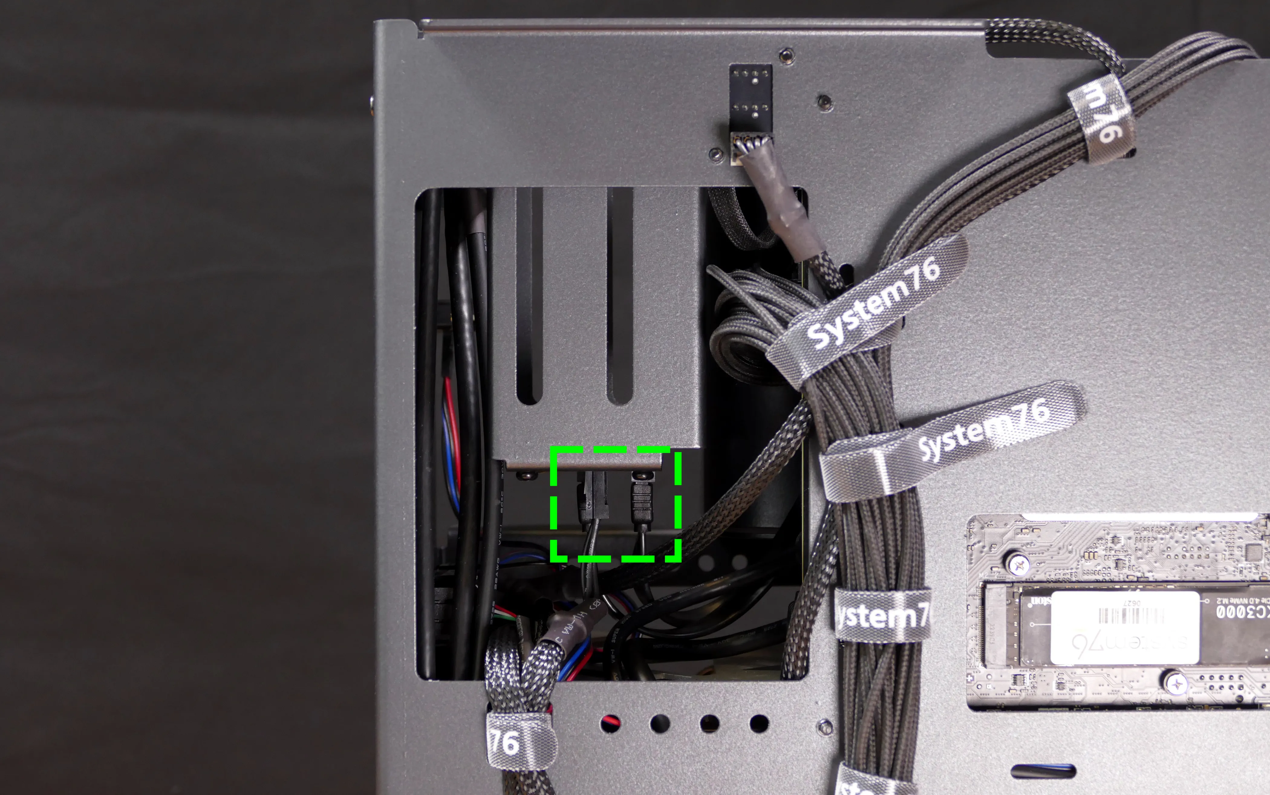
- Unscrew the two outer flat screws holding the top crossbar onto the front of the chassis.
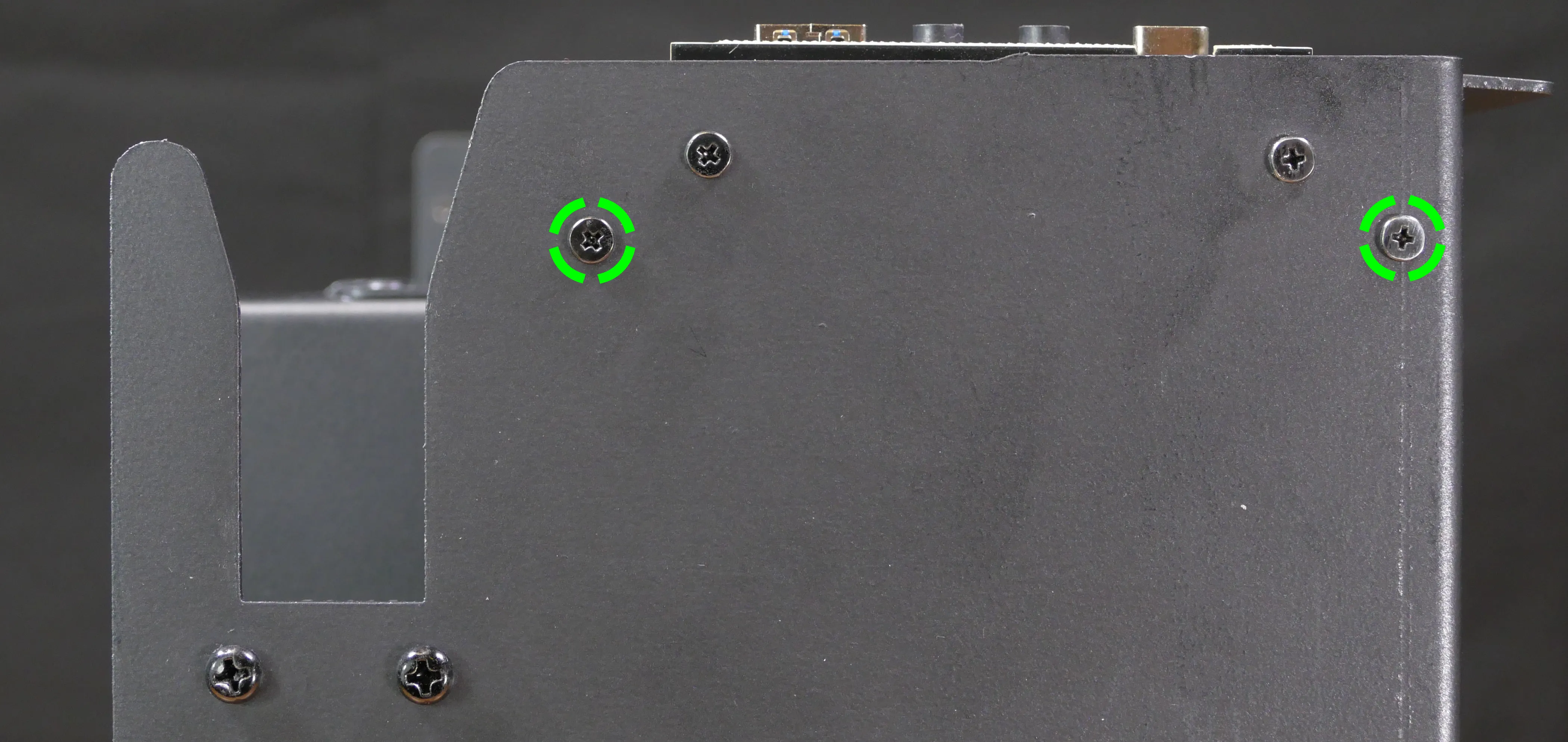
- Unscrew the two back screws holding the top crossbar onto the back of the chassis.
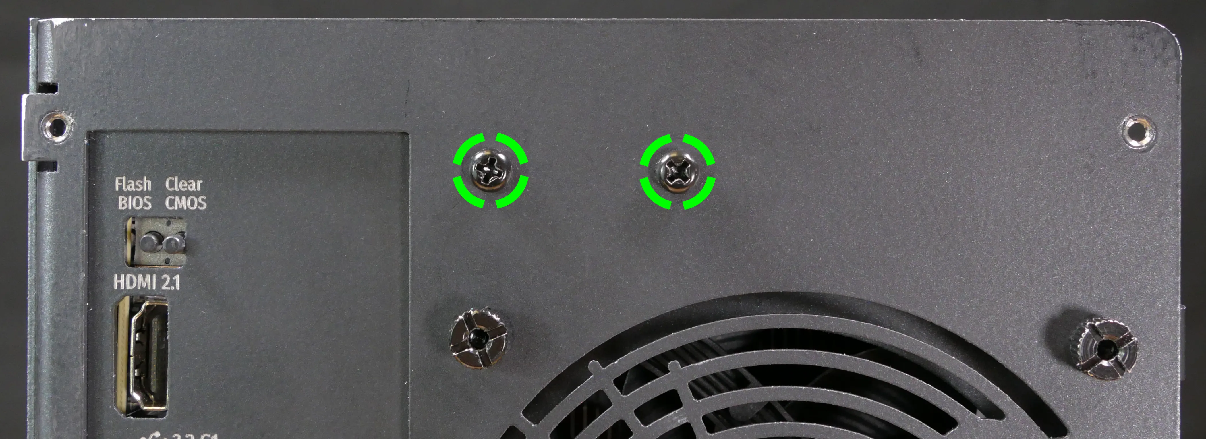
- Unscrew the two screws holding the CPU duct onto the top crossbar.

- Lift the top crossbar up and out of the chassis.
- Unscrew the four SATA backplane screws from the drive cage, then push the SATA backplane out through the top of the drive cage.

- Place the new SATA backplane into the drive cage and secure it with the four SATA backplane screws, then reinstall the drive cage (if necessary).
- Plug the 4-pin Berg power connector and SATA data cables into the SATA backplane.
- The order of the SATA data cables shouldn't matter as long as your operating system and software is configured to address disks by UUID (e.g.
/dev/disk/by-id/...) instead of by letter (e.g./dev/sd_). - By default, the
DATA1port connects to the innermost SATA connector on the motherboard, and theDATA0port connects to the outermost SATA connector on the motherboard.
- The order of the SATA data cables shouldn't matter as long as your operating system and software is configured to address disks by UUID (e.g.
- Reinstall the CPU shroud (if necessary), any 2.5" drives that were removed, the 2.5" drive cage cover, and the top case.
Replacing the top I/O:
Thelio Spark B1-N2 includes a top I/O module providing audio and USB ports. If the top ports are damanged or become defective, they can be replaced using the steps below.
Part numbers:
- The top I/O module's part number is
MYS7523 Rev. 4.0.
Tools required: Cross-head (Phillips) screwdriver
Time estimate: 30 minutes
Difficulty: Medium ●
Steps to replace the top I/O:
- Follow the steps above to remove the top case, remove the side brace, and remove the GPU.
- Unplug the
JAUD1header at the bottom-left corner of the motherboard.
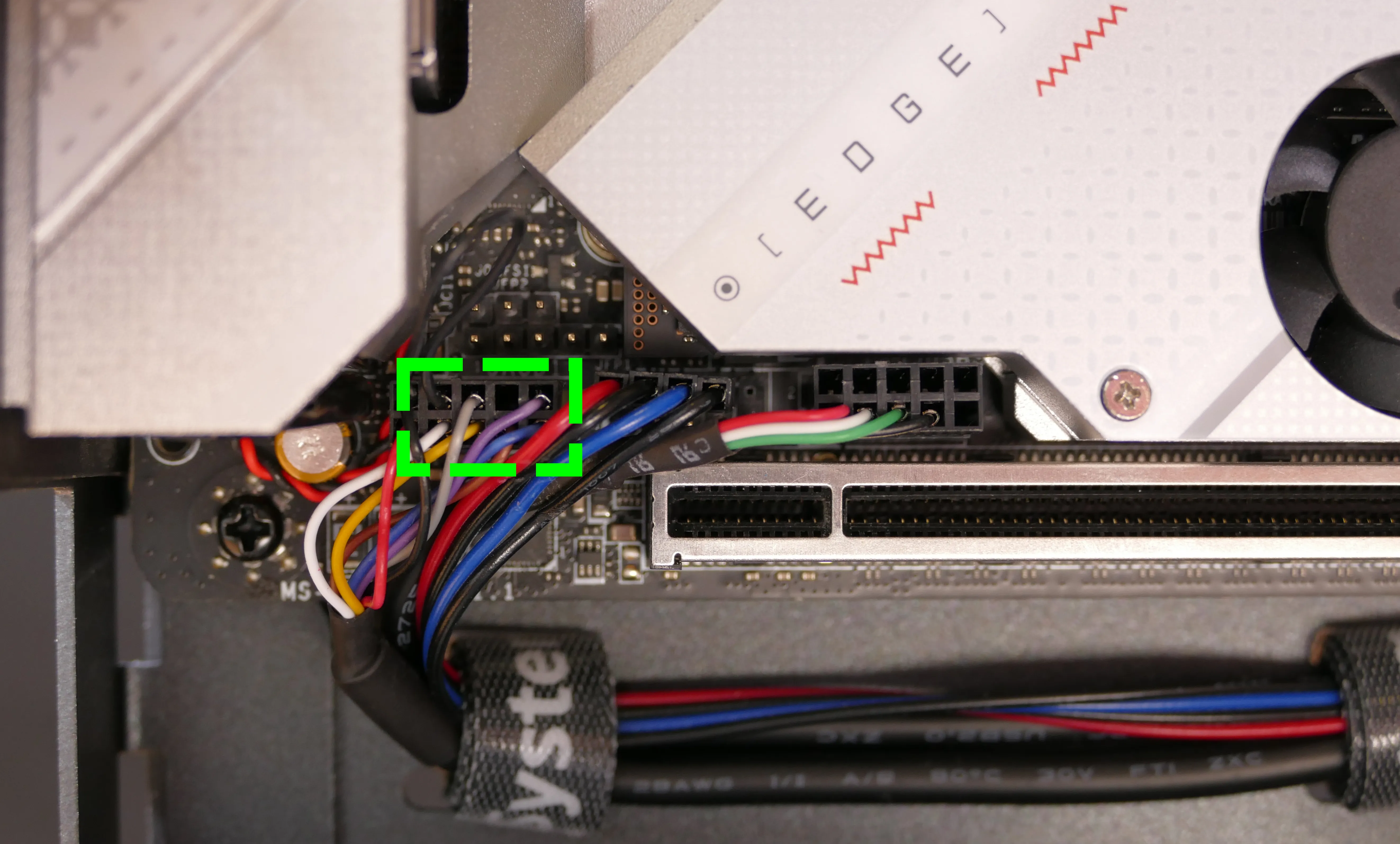
- Unplug the
JUSB1header (highlighted cyan below) andJUSB2header (highlighted green below) along the right edge of the motherboard.- The
JUSB1header is behind the CPU duct, but it can be unplugged without removing the duct. The duct has been removed for greater visibility in the below photo.
- The
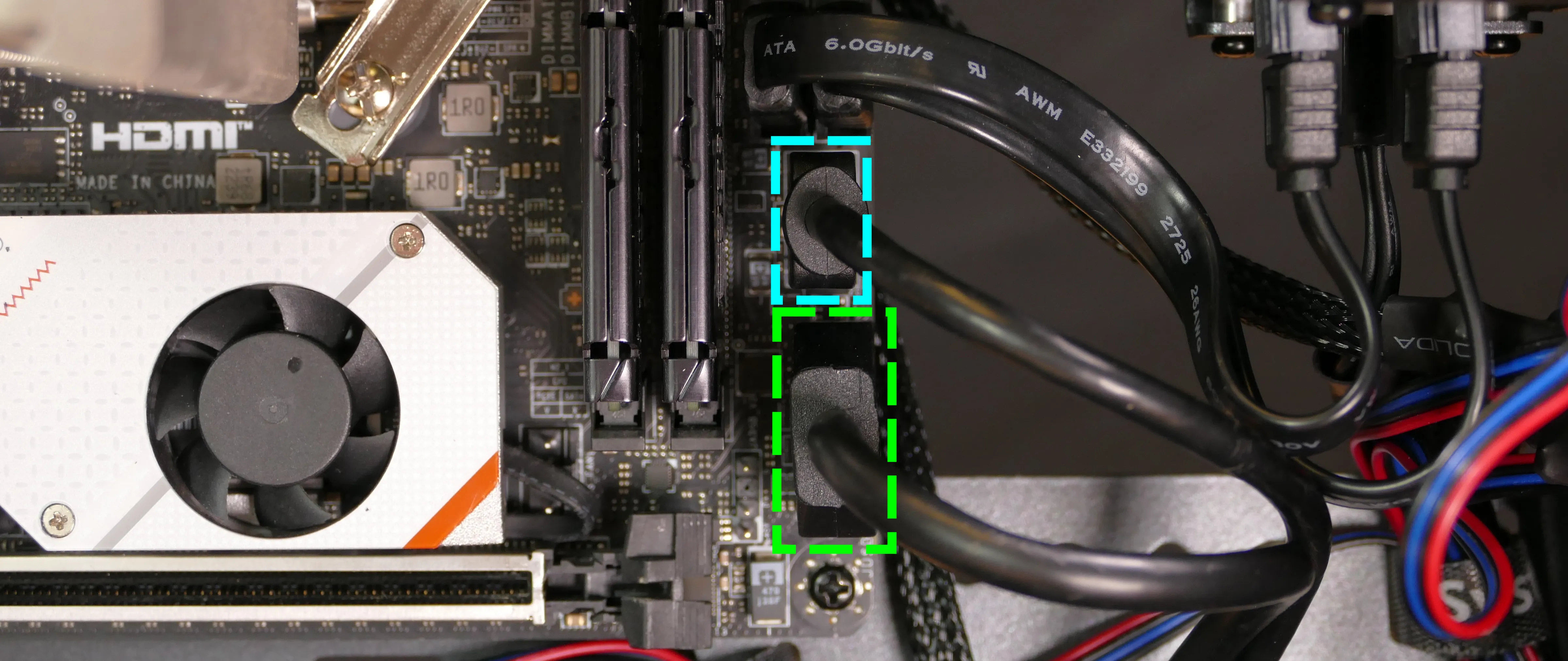
- Unscrew the two front screws holding the top I/O board onto the chassis.

- Remove the top I/O board from the system.
- Insert the new top I/O board into the system and screw it into place.
- Reconnect the audio and USB headers.
- Replace the side brace (if necessary), CPU shroud, and top case.
Troubleshooting the power button:
If the front power button doesn't power the machine on or doesn't light up when the system is powered on, try the following troubleshooting steps:
- Check if internal Thelio Io power button and LED work.
- Reseat the front power button to ensure it's making proper contact.
- Check the wiring for the front power button.
- Replace the front power button, if necessary.
Tools required: Cross-head (Phillips) screwdriver (optional)
Time estimate: 20 minutes
Difficulty: Medium ●
Steps to power the machine on using the internal power button:
- Follow the steps above to remove the top case.
- Ensure the system is plugged into power, and the power supply switch is in the 1 (On) position.
- Push the small button labeled
POWERon the Thelio-IO board.- The white LED below the button lights up to indicate when the system is powered on (and pulses when the system is suspended).

- If the Thelio-IO
POWERbutton powers the machine on and the LED lights up, then the issue is either the front power button or its connection to the Thelio-IO board. Check the front power button wiring. - If the Thelio-IO
POWERbutton and/or LED does not work, then the issue is either the Thelio-IO board or its connection to the motherboard. Check the wiring between the Thelio-IO board and the motherboard.
Steps to check the front power button wiring:
- Follow the steps above to remove the top case.
- On the back of the power button, the four pins should be connected to the four-wire connector as follows:

- On the front power button receptacle, the four-pin connector should have the red wire on the left and the black wire on the right (when viewed from the back of the computer.)

- The front power button receptacle should plug into the
PFPDport on the Thelio-IO board, with the red wire on the top (see the Thelio-IO wiring guide.)
Steps to replace the power button:
- Follow the steps above to remove the top case.
- Follow the instructions in the Replace the Thelio Power Button support article.
Thelio (thelio-b4)
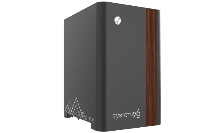
The System76 Thelio is a desktop with the following specifications:
- Processor options
- Supports Intel 12th Generation (Alder Lake) and 13th Generation (Raptor Lake) CPUs
- Motherboard
- MSI MEG Z690I UNIFY running System76 Firmware (non-open)
- Intel Z690 chipset
- Daughterboard
- Thelio Io board running open-source firmware
- Graphics options
- One GPU (PCIe 4.0 x16) of up to two-slot height
- GPU size:
- Internal clearance: 278.175mm
- Recommended maximum length: 268.175mm
- Tested with the following GPUs:
- Integrated Graphics
- 1x HDMI 2.1, 1x DisplayPort 1.4a
- NVIDIA GeForce GT 1030
- 1x HDMI 2.0b, 1x DisplayPort 1.4, 1x DVI-D (single-link)
- NVIDIA GeForce GTX 1650
- 1x HDMI 2.0b, 1x DisplayPort 1.4a, 1x DVI-D (dual-link)
- AMD Radeon RX 6500 XT
- 1x HDMI 2.1, 1x DisplayPort 1.4a
- AMD Radeon RX 6600
- 1x HDMI 2.1, 3x DisplayPort 1.4a
- NVIDIA GeForce RTX 3060
- 1x HDMI 2.1, 3x DisplayPort 1.4a
- Requires 650W PSU
- NVIDIA GeForce RTX 3060 Ti
- 1x HDMI 2.1, 3x DisplayPort 1.4a
- Requires 650W PSU
- NVIDIA GeForce RTX 3070
- 1x HDMI 2.1, 3x DisplayPort 1.4a
- Requires 650W PSU
- NVIDIA RTX A2000
- 4x Mini DisplayPort 1.4
- Requires 650W PSU
- NVIDIA RTX A4000
- 4x DisplayPort 1.4
- Requires 650W PSU
- Integrated Graphics
- Expansion
- 1x PCIe 4.0 x16 (GPU slot)
- Memory
- Up to 64GB (2x32GB) dual-channel DDR5 DIMMs @ 5600 MHz
- Tested with the following RAM modules (may ship with other tested modules):
- Crucial CT8G48C40U5 (8GB/stick)
- Kingston Fury KF556C40BB-8 (8GB/stick)
- Crucial CT16G48C40U5 (16GB/stick)
- Kingston Fury KF556C40BB-16 (16GB/stick)
- Crucial CT32G48C40U5 (32GB/stick)
- Kingston Fury KF556C40BB-32 (32GB/stick)
- Networking
- 1x 2.5-Gigabit Ethernet (Intel I225-V)
- Wi-Fi 6E + Bluetooth 5.2 (Intel AX211)
- Power
- C13 power cord
- 450W minimum PSU
- Some GPU configurations require 650W PSU
- Tested with the following PSU models (may ship with other tested models):
- Sound
- 3.5mm line out, line in, microphone jacks
- Up to 7.1-channel audio output
- Realtek ALC4080 audio chipset (with Savitech SV3H712 amplifier)
- HDMI, DisplayPort, USB-C DisplayPort audio (depending on GPU)
- Storage
- 2x M.2 (PCIe NVMe Gen 4) SSD
- Only active with 11th Gen CPUs.
- 1x M.2 (PCIe NVMe Gen 3 or SATA III)
- 4x 2.5" SATA
- 2x M.2 (PCIe NVMe Gen 4) SSD
- USB
- 2x USB Type-C with Thunderbolt 4
- Does not provide a DisplayPort over USB-C signal.
- Supports DisplayPort over USB-C passthrough when a GPU is connected to the associated Mini DisplayPort input.
- 2x USB 3.2 Gen 2 Type-A
- 4x USB 3.2 Gen 1 Type-A
- 2x USB Type-C with Thunderbolt 4
- Dimensions
- 32.7cm × 20.7cm × 29.1cm
Thelio (External Overview)
Back overview:

Power Switch Guide:
- 1: On
- 0: Off
Front/side overview:

Top/bottom overview:

Thelio (Internal Overview)
Left side overview:
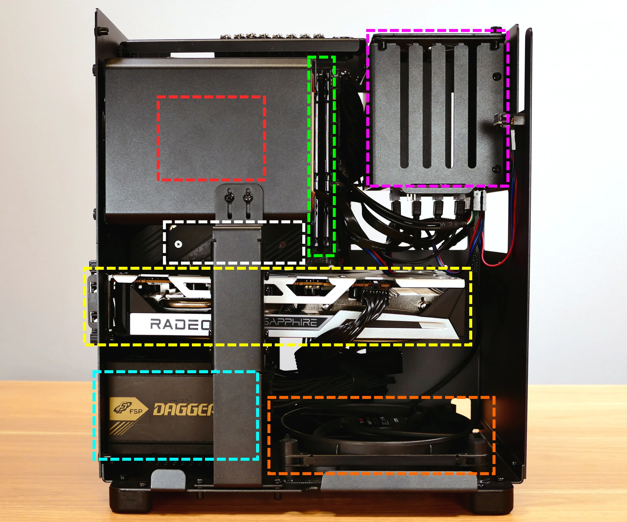
- CPU cooler & CPU are highlighted in red (located behind the CPU duct)
- RAM slots are highlighted in green
- 2.5" SATA drive cage is highlighted in pink
- M.2 slots 1 and 2 are highlighted in white (located underneath the heatsink)
- GPU (in PCIe 4.0 x16 slot) is highlighted in yellow
- Power supply is highlighted in cyan
- Bottom case fan is highlighted in orange
Right side overview:
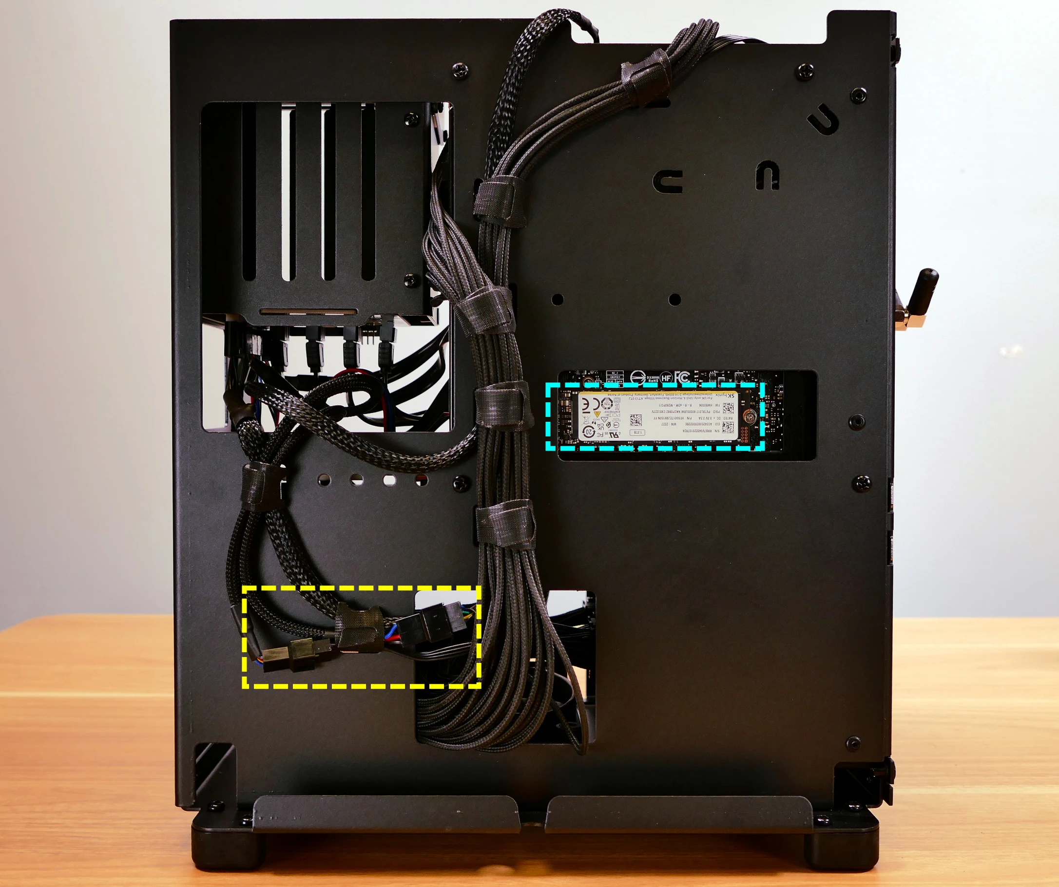
- M.2 slot 3 is highlighted in cyan
- CPU fan Y-cable connectors are highlighted in yellow
Front side overview:
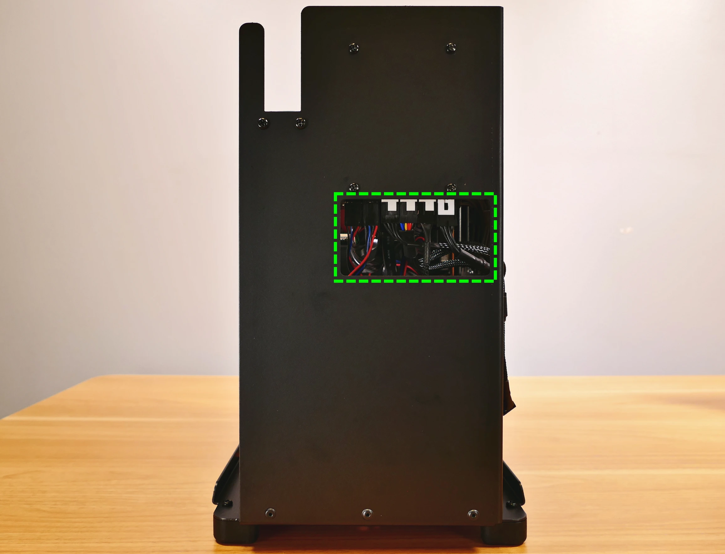
- Thelio-IO connector access cutout is highlighted in green
Top overview:
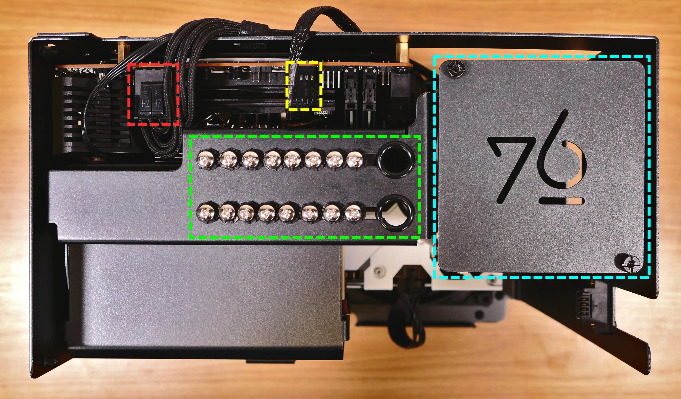
- 2.5" drive screws are highlighted in green
- 2.5" drive cage cover is highlighted in cyan
- Motherboard CPU fan header is highlighted in yellow
- Connects to Thelio-IO board
- CPU power connector is highlighted in red
- Connects to power supply
See the repairs page for detailed information about installing or replacing components.
Thelio (Parts & Repairs)
Many components in your Thelio can be upgraded or replaced as necessary. This page uses photos of the initial revision for this generation (B4-0). Minor case details may vary on newer units, but screw counts, general component locations, and other details should remain the same unless otherwise noted.
Power the machine off, switch off the power supply, and unplug all peripherals before working with any internal components. Then, follow these step-by-step guides for instructions:
- Replacing the front accent strip
- Removing the top case
- Adding/removing 2.5" storage drives
- Replacing the bottom case fan
- Replacing the GPU
- Removing the CPU duct
- Replacing the RAM
- Replacing the M.2 drives
- Replacing the CPU fans
- Replacing the CPU cooler/thermal paste and CPU
- Replacing the power supply
- Replacing the Thelio-IO board
- Troubleshooting the power button
Replacing the front accent strip:
Thelio includes a customizable accent panel on the front of the case, which can be swapped to change the case's look and feel. The instructions for swapping the accent are also available in video form.
Tools required: None
Time estimate: 30 seconds
Difficulty: Easy ●
Steps to replace the front accent strip:
- Place the Thelio on the edge of the desk so the front side is hanging off of the desk.
- The Thelio can alternatively be lifted or tilted so the front of the computer is hovering above the desk.
- Slide the accent strip down to unlock it.
- The accent can be gripped at the bottom edge.
- Pull the accent strip off of the case, starting with the bottom edge.
- Place the new accent strip onto the front of the case and slide it up to lock it into place.

Removing the top case:
The top case can be removed to access the internal components.
Tools required: Cross-head (Phillips) screwdriver (optional)
Time estimate: 1 minute
Difficulty: Easy ●
Steps to remove the top case:
- Remove the four outer screws holding the top case onto the machine.

- Slide the top case up and off of the machine.
Adding/removing 2.5" storage drives:
Thelio B4 supports up to four 2.5" SATA III drives.
Tools required: Cross-head (Phillips) screwdriver (optional)
Time estimate: 5 minutes
Difficulty: Easy ●
Steps to add/remove 2.5" storage drives:
- Follow the steps above to remove the top case.
- Unscrew the two screws securing the drive bay's cover, highlighted green below.

- If you are adding a new drive, pop out a black plastic ring on the top crossbar and slide out four screws (per drive).
- Insert four screws into each 2.5" storage drive you wish to install.
- Slide each 2.5" drive into one of the slots leading to the Thelio-IO board.


Thelio B4 with one 2.5" screw ring removed and one 2.5" drive installed.
- Replace the black plastic screw rings and the 2.5" drive bay cover.
Replacing the bottom case fan:
Thelio B4 has one case-mounted intake fan on the bottom of the chassis.
Tools required: Cross-head (Phillips) screwdriver
Time estimate: 20 minutes
Difficulty: Medium ●
Steps to replace the bottom case fan:
- Follow the steps above to remove the top case.
- Unplug the fan's cable from the Thelio-IO daughterboard.
- The bottom case fan plugs into the
INTAKE0port on the Thelio-IO board. - When viewed from the front of the case, this connector is second from the right.
- The bottom case fan plugs into the

- Unscrew the four fan screws from the bottom of the machine.
- To avoid damaging other components, place the machine on its front side when working with the bottom surface.

- Remove the old fan from the case.
- When installing the fan, mount the components in the following order:
- Chassis
- Dust filter
- Acrylic spacer
- Fan
- The new fan's cable should be oriented towards the front-right corner of the case. Thread the new fan's cable through the opening in the back of the case and through the two velcro connectors leading to the Thelio-IO board.
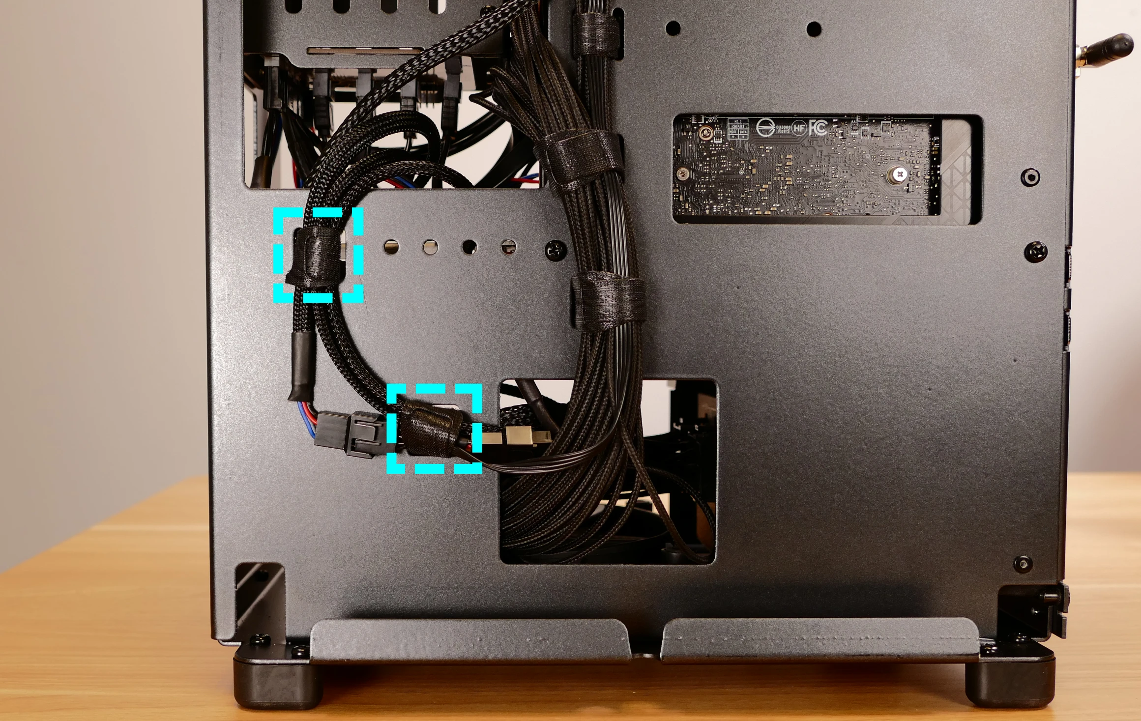
Replacing the GPU:
Thelio supports one dual-slot dedicated GPU. The GPU slot is a PCIe 5.0 x16 slot.
Tools required: Cross-head (Phillips) screwdriver
Time estimate: 10 minutes
Difficulty: Medium ●
Steps to replace the GPU:
- Follow the steps above to remove the top case.
- Unscrew the two back screws holding the PCIe bracket in place, and remove the PCIe bracket.

- Unscrew the four screws holding the side GPU brace in place. Remove the brace.

- If you're removing a GPU, unplug the GPU power cable from the right side of the card. Hold down the latch on the connector while unplugging the cable.

- Push and hold the latch on the motherboard to free the PCIe connection, then pull the card out of the slot.

- After inserting the new GPU into its slot, connect the power cable.
- Once the GPU is installed, replace the side GPU brace, back PCIe bracket, and top case.
- The side GPU brace includes screws to adjust for the height and depth of the graphics cards.
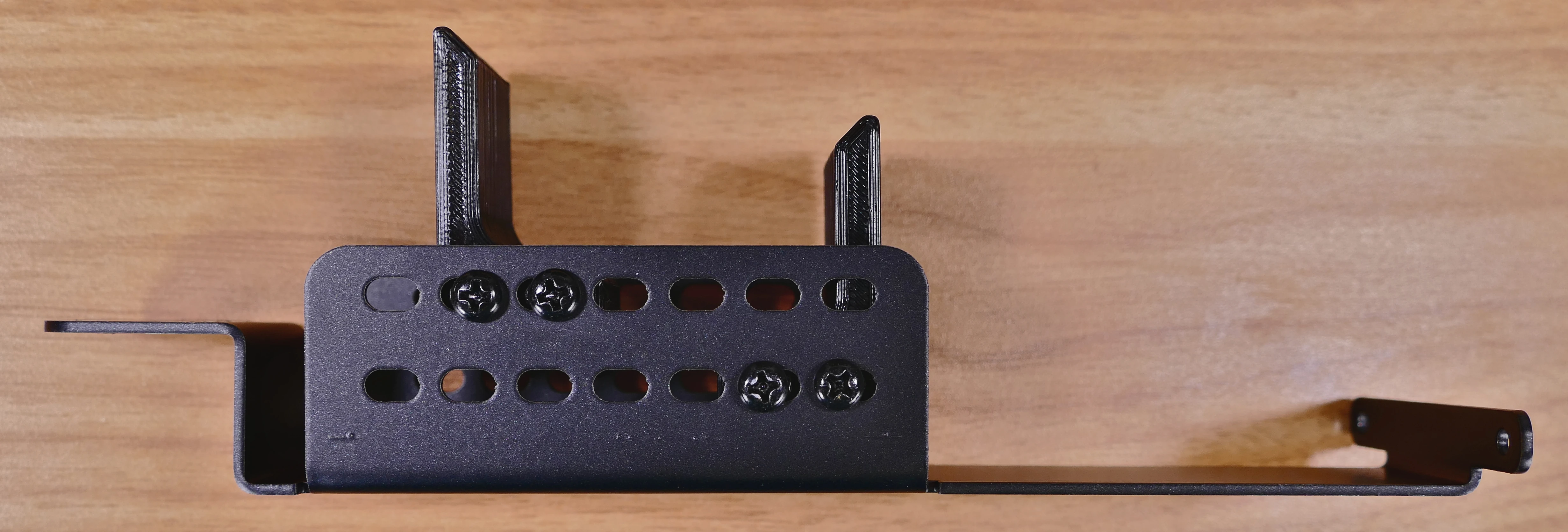
The GPU brace's primary function is to prevent damage during shipping. The system can be run without the brace if it doesn't fit an upgraded card; the back PCIe bracket provides primary support for the GPU.
Removing the CPU duct:
The CPU duct guides airflow through the CPU cooler. It covers the CPU and partially obstructs the RAM slots and top GPU.
Tools required: Cross-head (Phillips) screwdriver
Time estimate: 7 minutes
Difficulty: Easy ●
Steps to remove the CPU duct:
- Follow the steps above to remove the top case and remove the GPU brace.
- The GPU can also be removed to provide more room for working with the components.
- Unplug the connector for the front CPU fan.
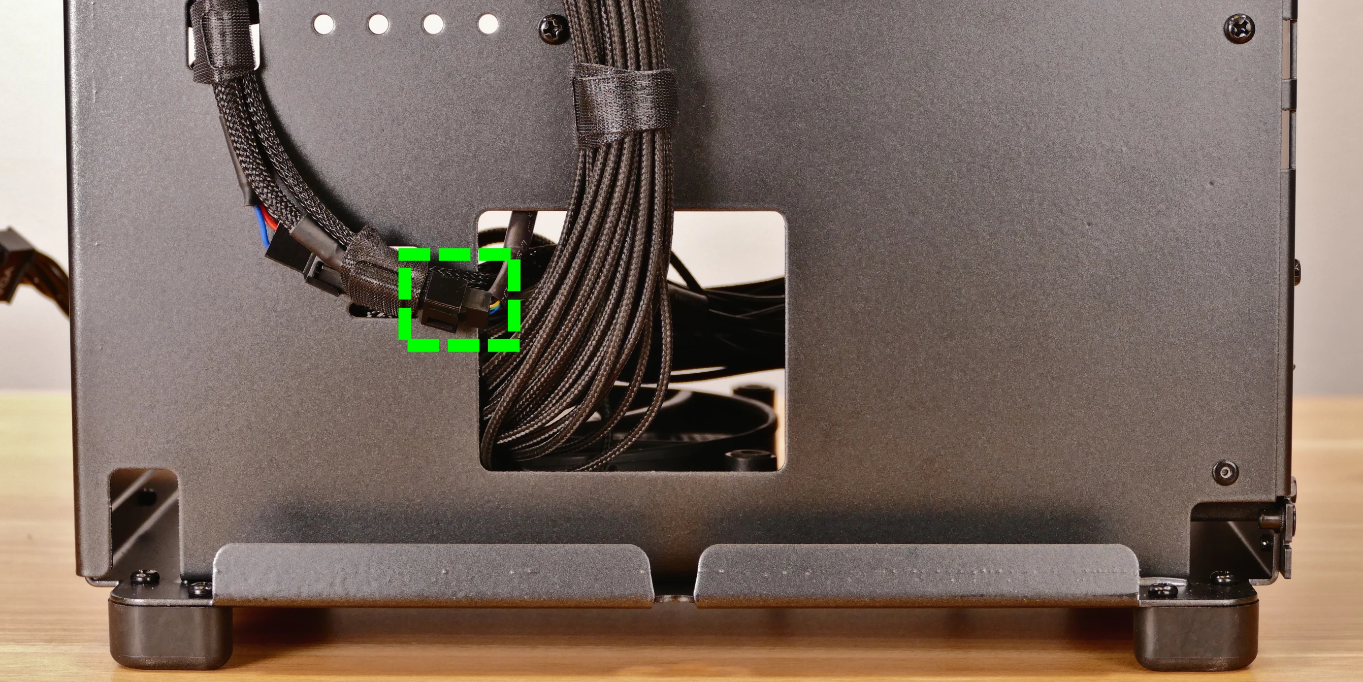
- Unscrew the four back screws holding the CPU duct in place.
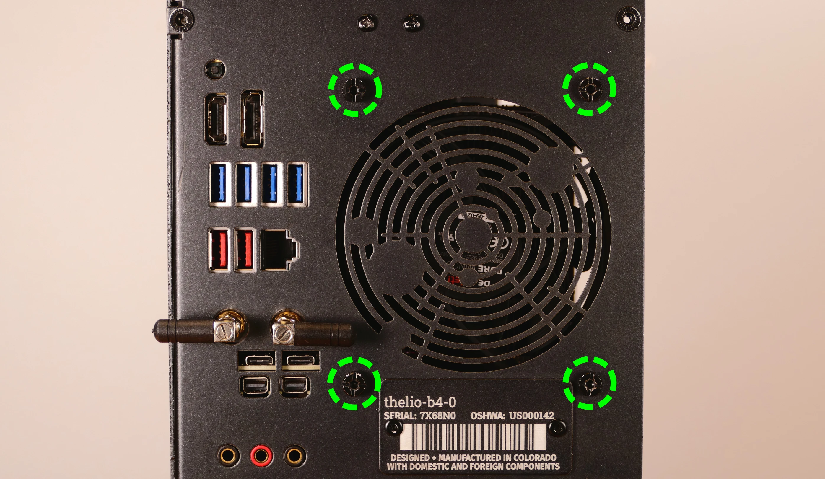
- Pull the CPU duct away from the machine.
Replacing the RAM:
Thelio B4 supports up to 64GB (2x32GB) of RAM. The RAM sticks are DDR5 DIMMs (non-ECC) running at a speed of up to 5600MHz. If you've purchased new RAM, need to replace your RAM, or are reseating your RAM, follow these steps.
Tools required: Cross-head (Phillips) screwdriver
Time estimate: 15 minutes
Difficulty: Medium ●
Steps to replace the RAM:
- Follow the steps above to remove the top case and remove the CPU duct.
- To remove an existing RAM stick, flip the top latch up away from the stick, then pull the stick out of the slot, starting from the top edge. (The bottom of the RAM slot does not move.)

- Make sure the tab on the top of the slot is open (pulled upwards), then insert the new RAM (or re-seat the existing RAM) into the slot, starting with the bottom edge.
- The RAM stick will only fit in one direction. The larger group of pins goes on top.
- If you are only using one RAM stick, place it in the right-side slot (farthest from the CPU.)
- Replace the top case.
Replacing the M.2 drives:
Thelio B4 has three M.2 slots (M key), supporting M.2 size 2280.
- Back of motherboard (slot 3):
- Supports PCIe NVMe Gen 4.
- Front of motherboard, front of switch (slot 1):
- Supports PCIe NVMe Gen 4.
- Front of motherboard, back of switch (slot 2):
- Supports PCIe NVMe Gen 3 and SATA III.
Tools required: Cross-head (Phillips) screwdriver
Time estimate: 30 minutes
Difficulty: Medium ●
Steps to replace the M.2 drive (slot 3):
- Follow the steps above to remove the top case.
- Unscrew the retainer screw opposite the M.2 slot.

- Remove the existing M.2 drive by pulling it out of the slot.
- Insert the new M.2 drive into the slot and hold it in place.
- Replace the retainer screw.
Steps to replace the M.2 drives (slots 1 and 2):
- Follow the steps above to remove the top case, remove the GPU brace and GPU, and remove the CPU duct.
- Removing the GPU is optional but recommended to provide more working space and avoid damage.
- Unscrew and remove the M.2 heatsink.
- The heatsink screws are held captive, and will not fully come out of the heatsink.
- It may take some pressure to remove the heatsink and thermal tape from the M.2 drive. After unscrewing the heatsink, pull slowly to avoid breaking the thermal tape.

- If installed, the SSD in slot 1 is held in place by the heatsink, and will be freed when the heatsink is removed.

- If you are accessing M.2 slot 2, remove the SSD from slot 1, then unscrew the two M.2 switch screws and pull the M.2 switch straight away from the motherboard.
- The M.2 switch plugs into the motherboard on the right side.
- The M.2 slot 1 socket can be used to grasp the switch while pulling.

- Flip the M.2 switch over to reveal M.2 slot 2 on the back of the switch.
- Unscrew the retainer screw opposite the M.2 slot.

- Remove the existing M.2 drive by pulling it out of the slot.
- Insert the new M.2 drive into the slot and hold it in place.
- Replace the retainer screw.
- Replace the M.2 switch, SSD in M.2 slot 1 (if installed), M.2 heatsink, CPU duct, GPU, GPU brace, and top case.
- If you are installing an SSD in M.2 slot 1 for the first time, remove any protective plastic that may be covering the thermal tape.
Replacing the CPU fans:
Thelio B4 contains two CPU fans. One is mounted on the CPU duct, and one is mounted on the cooler.
Tools required: Cross-head (Phillips) screwdriver
Time estimate: 25 minutes
Difficulty: Medium ●
Steps to replace the duct-mounted CPU fan:
- Follow the steps above to remove the top case, remove the GPU brace, and remove the CPU duct.
- Unscrew the four screws holding the fan onto the duct.

- When reinstalling the fan into the CPU duct, the spinning side should face outward (towards the front of the case), and the cable should point towards the bottom-right corner of the open side of the duct.
- Overtightening the fan's screws may cause fan noise; if the fan is creating excessive noise, try slightly loosening some of the screws.
Steps to replace the cooler-mounted CPU fan:
- Follow the steps above to remove the top case, remove the GPU brace and GPU, and remove the CPU duct.
- Pull the corners of the fan's top clip away from the heatsink it's held to.
- Alternatively, the opposite side of the bracket (clipped onto the heatsink) can be released first.
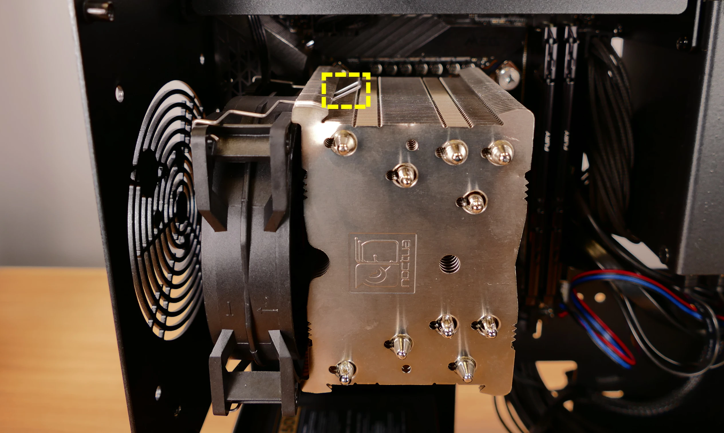
- Repeat the process for the bottom clip, then pull the fan and clips away from the CPU cooler.
- Unplug the fan connector and free the cable through the six velcro straps.
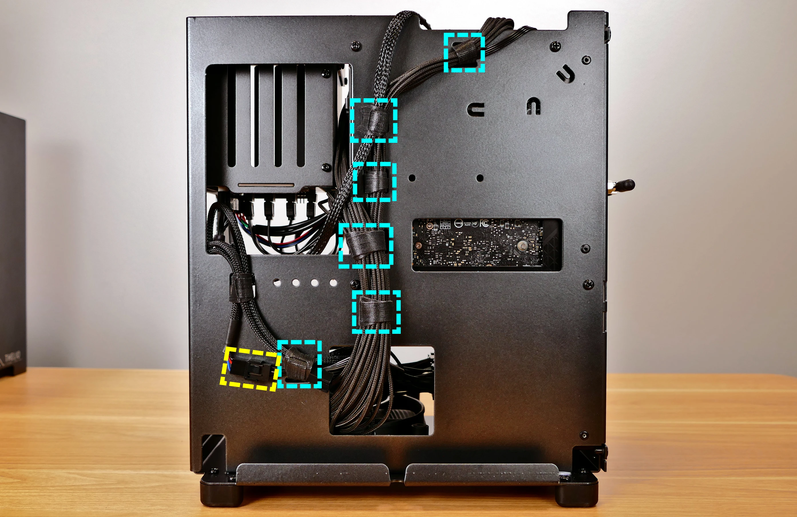
- When reinstalling the CPU cooler fan, the side with a stationary cover should face the back of the case, while the spinning side should face the CPU cooler.
Replacing the CPU cooler and CPU:
The CPU cooler dissipates heat from the CPU to the heatsink, where the CPU fans expel it from the system. Depending on your climate and the age of the machine, replacing the thermal paste between the CPU and the cooler/heatsink may help the system run cooler.
The CPU uses an Intel LGA 1700 socket. The CPU cooler is a Noctua NH-U9S.
Tools required: Cross-head (Phillips) screwdriver, thermal paste
Time estimate: 45 minutes
Difficulty: High ●
Steps to remove the CPU cooler/thermal paste:
- Follow the steps above to remove the top case, remove the GPU brace and GPU, remove the CPU duct, and remove the cooler-mounted CPU fan.
- While holding the CPU cooler in place so it doesn't fall, unscrew the two screws holding the CPU cooler crossbar onto the vertical mounting brackets.
- The screws are held captive, and will not fully come out of the crossbar.
- Only the two outer screws need to be removed; the center screw holding the horizontal crossbar onto the heatsink does not need to be removed.

- The cooler will come away from the CPU.
- Using a paper towel, clean the existing thermal paste off of the heatsink and CPU. You may also use a small amount of rubbing alcohol if the old paste is dried or difficult to remove.

Steps to replace the CPU:
- Place the computer on its side so the motherboard is facing up.
- Push the locking pin outward until it's able to spring away from the motherboard.
- Caution: the locking pin may spring up with significant force when freed.

- Flip the CPU holder away from the CPU.
- The CPU holder opens in the opposite direction from the locking pin.

- Carefully lift the CPU out of the CPU socket.
- Be careful not to bend any of the gold pins on the CPU socket, and do not touch the gold pads on the CPU.

- Gently place the new CPU into the socket.
- When reinstalling the CPU, be sure to match the original orientation, with the triangle on the CPU pointing to the bottom left of the motherboard.
- The triangle on the CPU should match the triangle on the top of the CPU cover.
- Flip the CPU cover back onto the CPU and push the locking pin down into place.
Steps to install the thermal paste/CPU cooler:
- Draw an
Xshape of thermal paste onto the CPU.

- Place the CPU cooler onto the CPU; while holding it in place, screw each end of the cooler crossbar onto one of the mounting brackets.
- The cooler should be oriented so the hole in the vertical center of the heatsink is facing the right side (front of the case).
- Insert each screw partially first, then fully tighten both.
- Set the computer upright, then reinstall the cooler-mounted CPU fan, CPU duct, GPU bracket, and top case.
Replacing the power supply:
The power supply unit (PSU) is modular and can be replaced with another unit of the same model. Different models may not be compatible with the cabling pre-installed in the Thelio.
Tools required: Cross-head (Phillips) screwdriver
Time estimate: 20 minutes
Difficulty: Medium ●
Steps to replace the power supply:
- Follow the steps above to remove the top case and remove the GPU brace and GPU.
- Unplug all of the modular cabling from the back of the PSU.
- Some of the cables may be easier to unplug after the PSU has been unscrewed/removed from the case.

- Unscrew the four screws holding the PSU in from the back of the case.

- Remove/replace the PSU.
- The replacement PSU should be installed with the fan facing the bottom of the case.
- The PSU will need to be held up to the back of the case while it is screwed in.
- After screwing in the replacement PSU, use the labels and pin counts on the cables and ports to ensure the power cables are reconnected in the proper locations.
- Remember that not all of the available connectors will plug into the PSU-- the 8-pin (6 + 1) connector is to be plugged into the GPU.
Replacing the Thelio-IO board:
Tools required: Cross-head (Phillips) screwdriver
Time estimate: 25 minutes
Difficulty: High ●
The Thelio-IO board handles the front power button, fan control, and 2.5" SATA connectors for the system. If the Thelio-IO board becomes defective, it can be replaced using the instructions below.
Steps to replace the Thelio-IO board:
- Follow the steps above to remove the top case and remove the 2.5" drive cage cover and any 2.5" drives that are installed.
- Use the cutouts on the front right corner of the chassis to unplug all cabling from the Thelio-IO board.
- The rightmost connector requires pulling the white tab while unplugging.
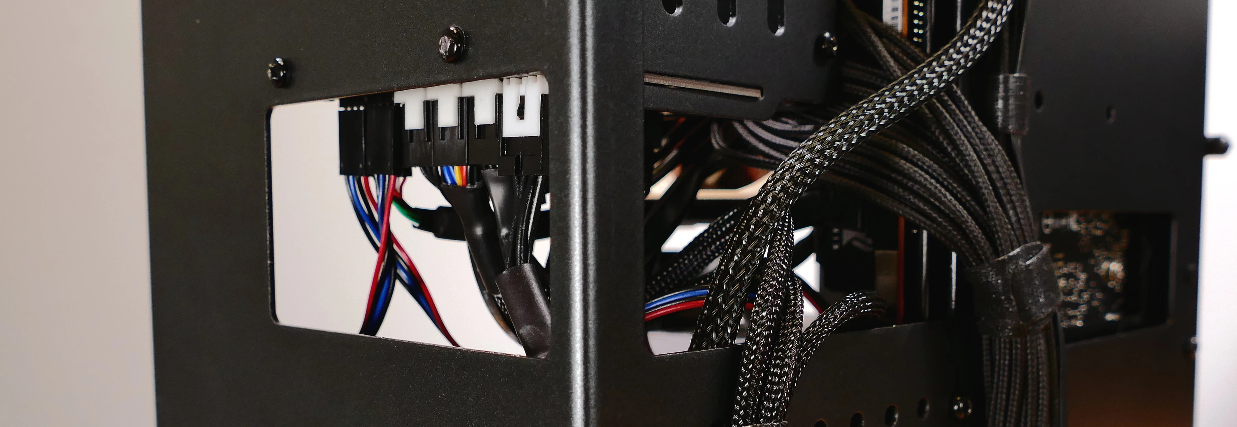
- Unscrew the two screws on the right side of the drive cage (next to the front of the machine.)

- While pulling the loose side of the drive cage away from the Thelio-IO board, move the board down and out of the drive cage.
- Place the new Thelio-IO board into the drive cage and replace the screws and wiring.
Thelio-IO wiring guide:
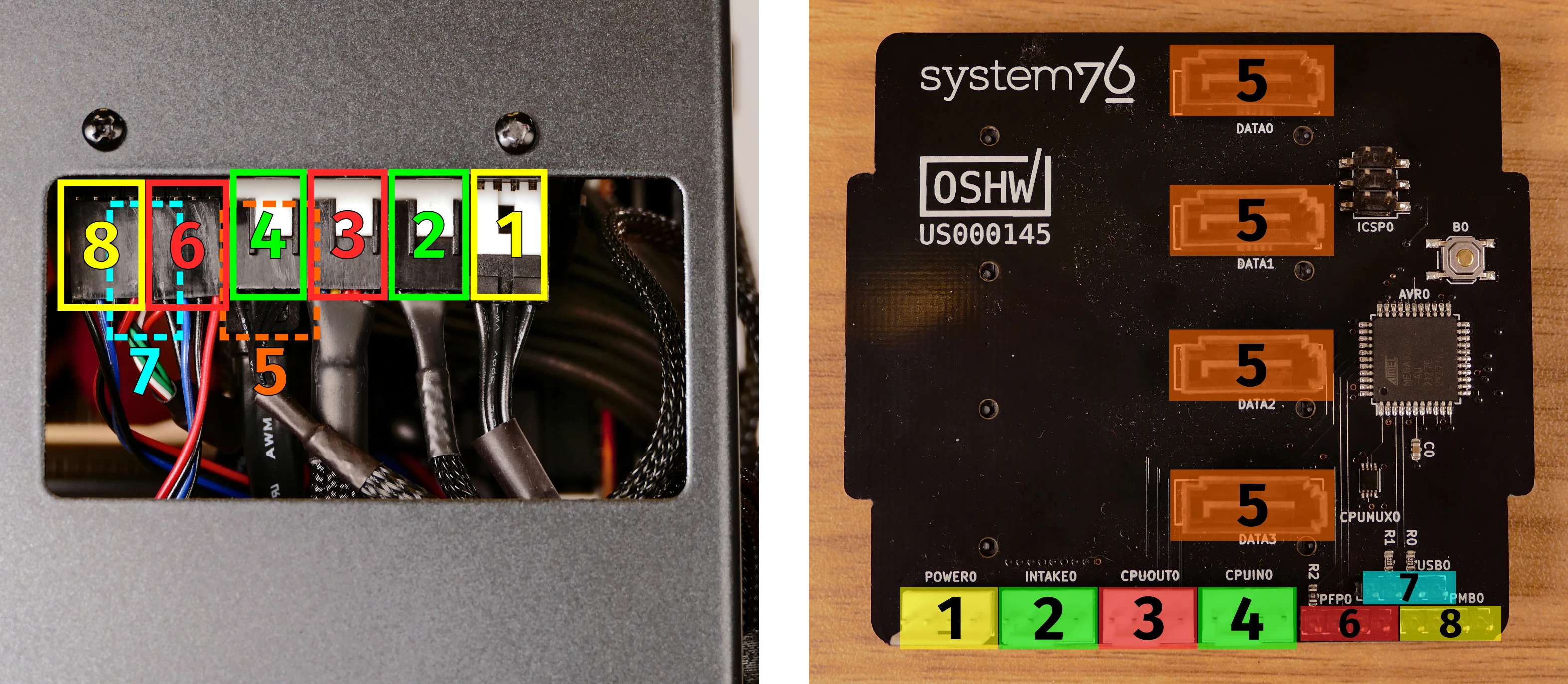
- When wiring the Thelio-IO board, refer to the above image and the following guide. The ports are numbered in the suggested connection order based on position and size.
- 1:
POWER0- to the power supplyPERIPHERALport (via 4-pin Molex adapter.) - 2:
INTAKE0- to the bottom case fan. - 3:
CPUOUT0- to a Y-cable connecting to both CPU fans. - 4:
CPUIN0- to theCPU_FAN1header at the top of the motherboard.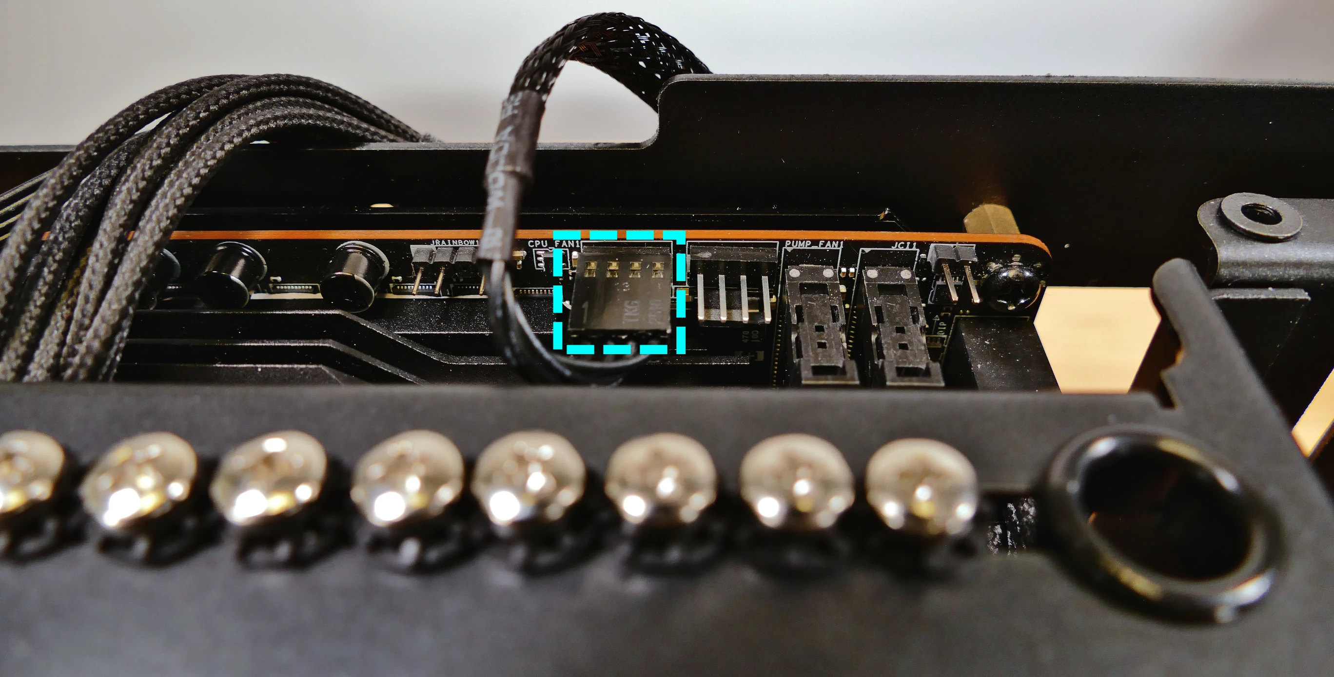
- 5:
DATA0/1/2/3- to SATA ports #1/#2/#3/#4 on the motherboard, highlighted yellow below.- The ports are located next to the RAM slots.
- These connectors provide data transfer for the 2.5" drive slots.
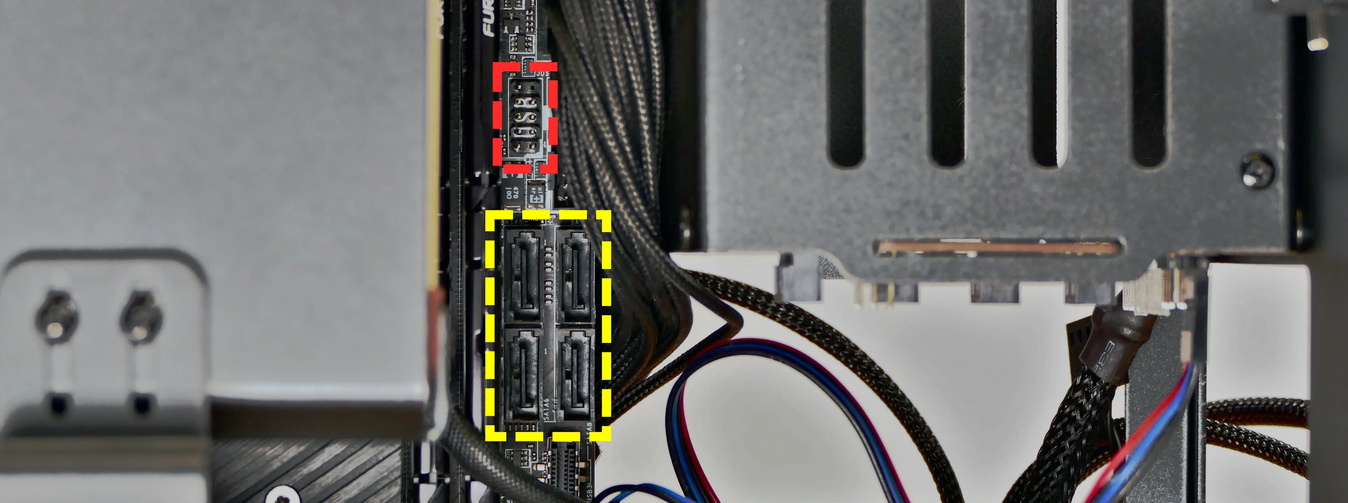
- 6*:
PFP0- to the power button receptacle on the front panel. - 7*:
USB0- to theJUSB1header on motherboard, highlighted red above.- The
JUSB1port is located above the four SATA ports. - On the Thelio-IO board, the row of four pins plugs in, while the row of five pins hangs off the back and does not plug in.
- This connector provides fan control and firmware updates.
- The
- 8*:
PMB0- to thePower SwitchandPower LEDpins (the four bottom-left pins of theJFP_1header) on the motherboard.- On the motherboard, the red wire goes on the bottom and the black wire goes on the top.
- The
JFP_1header is just above the GPU (if installed).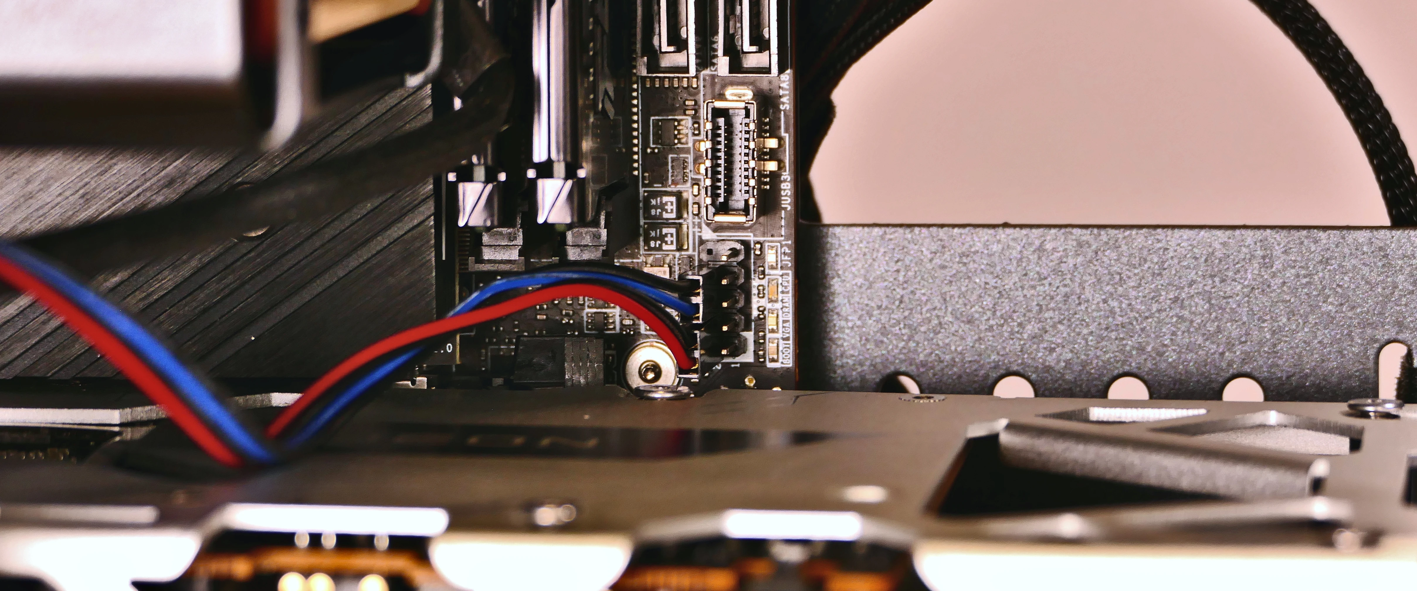
- * For all connectors with multi-colored wires plugging into the Thelio-IO board, the red wire goes on the right side (viewing from the front of the computer.)
- 1:
Troubleshooting the power button:
If the front power button doesn't power the machine on or doesn't light up when the system is powered on, try the following troubleshooting steps:
- Ensure the system powers on normally using the internal power button.
- Reseat the front power button to ensure it's making proper contact.
- Check the wiring for the front power button.
- Replace the front power button, if necessary.
Tools required: Cross-head (Phillips) screwdriver (optional)
Time estimate: 20 minutes
Difficulty: Medium ●
Steps to power the machine on using the internal power button:
- Follow the steps above to remove the top case.
- Ensure the system is plugged into power, and the power supply switch is in the 1 (On) position.
- Push the small button labeled
B0on the Thelio-IO board.
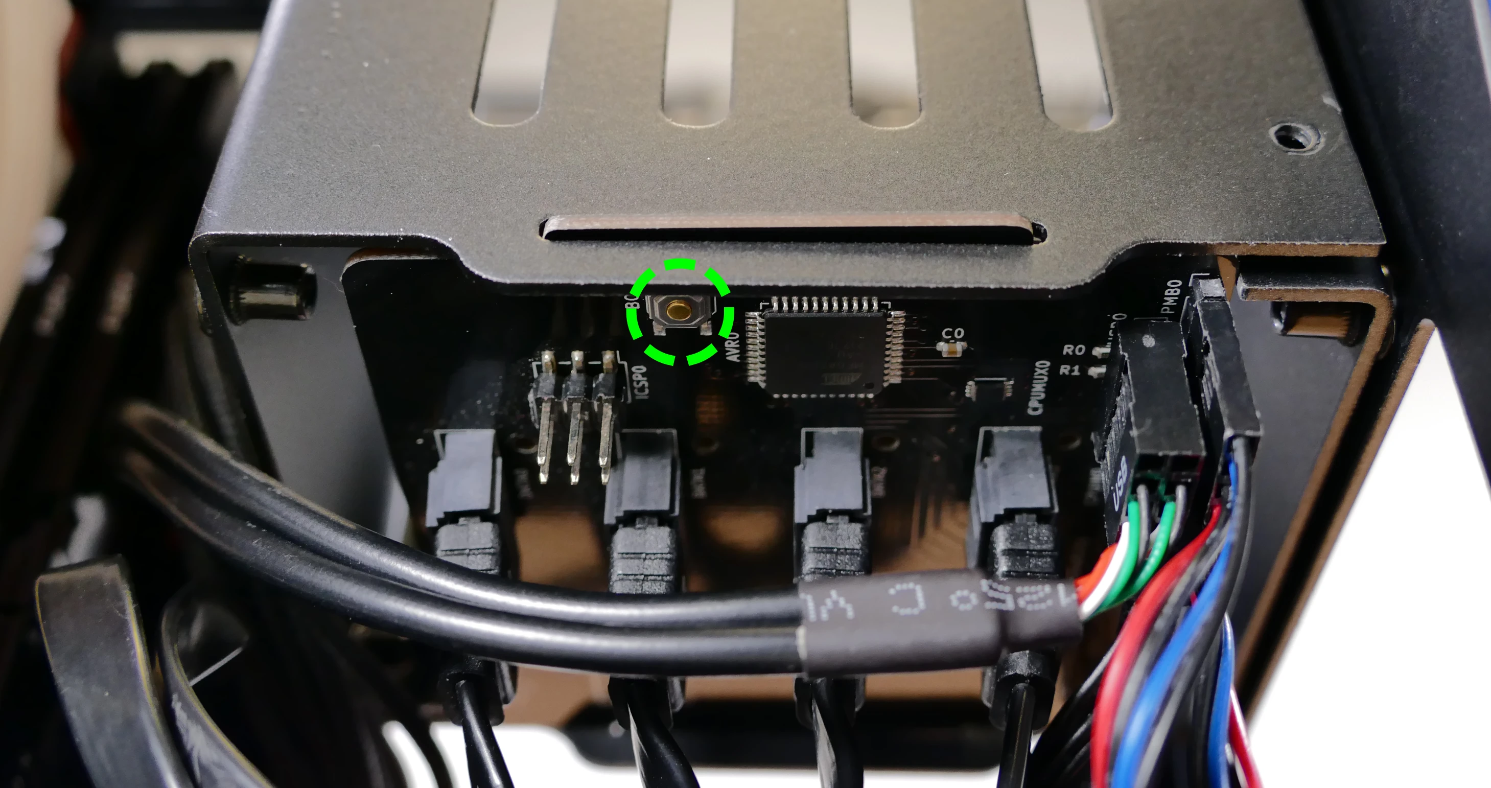
- If the Thelio-IO
B0button powers the machine on, then the issue is either the front power button or its connection to the Thelio-IO board. Check the front power button wiring. - If the Thelio-IO
B0button does not work, then the issue is either the Thelio-IO board or its connection to the motherboard. Check the wiring between the Thelio-IO board and the motherboard.
Steps to check the front power button wiring:
- Follow the steps above to remove the top case.
- On the back of the power button, the four pins should be connected to the four-wire connector as follows:

- On the front power button receptacle, the four-pin connector should have the red wire on the left and the black wire on the right (when viewed from the back of the computer.)

- The front power button receptacle should plug into the
PFPDport on the Thelio-IO board, with the red wire on the top (see the Thelio-IO wiring guide.)
Steps to replace the power button:
- Follow the steps above to remove the top case.
- Follow the instructions in the Replace the Thelio Power Button support article.
Thelio Major (thelio-major-r3)
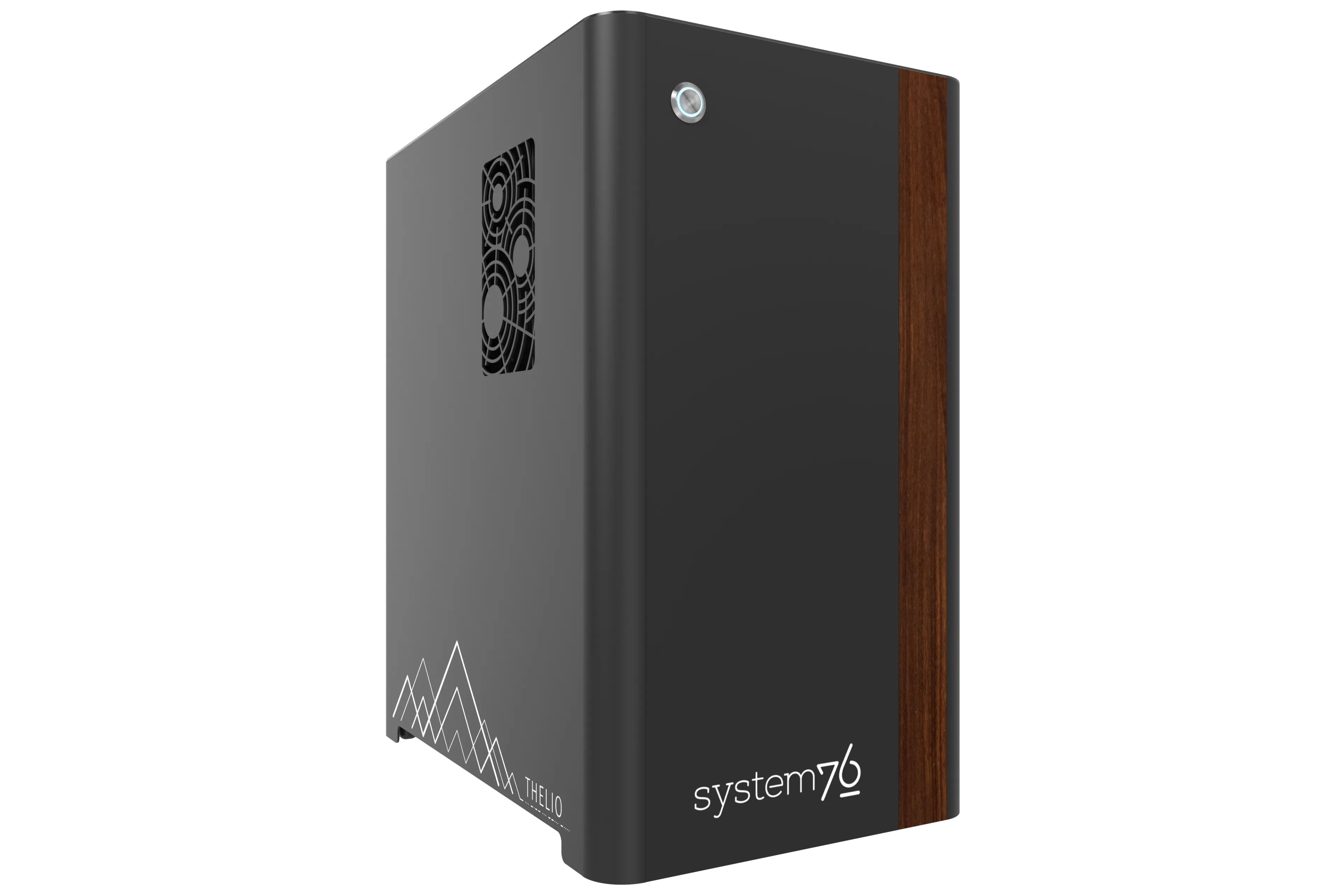
The System76 Thelio Major is a desktop with the following specifications:
- Processor options
- Supports AMD Ryzen 7000 series (Zen 4) CPUs
- Motherboard
- Gigabyte X670E Aorus Extreme running System76 Firmware (non-open)
- AMD X670 chipset
- Daughterboard
- Thelio Io board running open-source firmware
- Graphics options
- Up to two dedicated GPUs
- Primary GPU slot:
- PCIe 5.0 x16
- Runs at x8 bandwidth if either of the bottom two M.2 slots are populated
- Up to 4-slot height
- PCIe 5.0 x16
- Secondary GPU slot:
- PCIe 4.0 x4
- Fits physical x16 cards, runs at x4 bandwidth
- Up to 2-slot height
- PCIe 4.0 x4
- Primary GPU slot:
- GPU size:
- Internal clearance: 396.50mm
- Recommended maximum length: 386.50mm
- Tested with the following GPUs:
- NVIDIA GeForce GT 1030
- 1x HDMI 2.0b, 1x DisplayPort 1.4, 1x DVI-D (single-link)
- AMD Radeon RX 6500 XT
- 1x HDMI 2.1, 1x DisplayPort 1.4a
- AMD Radeon RX 6600
- 1x HDMI 2.1, 3x DisplayPort 1.4a
- AMD Radeon RX 6700 XT
- NVIDIA GeForce RTX 3060
- 1x HDMI 2.1, 3x DisplayPort 1.4a
- NVIDIA GeForce RTX 3060 Ti
- 1x HDMI 2.1, 3x DisplayPort 1.4a
- NVIDIA GeForce RTX 3070
- 1x HDMI 2.1, 3x DisplayPort 1.4a
- NVIDIA GeForce RTX 3070 Ti
- 1x HDMI 2.1, 3x DisplayPort 1.4a
- NVIDIA GeForce RTX 4070 Ti
- 1x HDMI 2.1a, 3x DisplayPort 1.4a
- NVIDIA GeForce RTX 4080
- 1x HDMI 2.1a, 3x DisplayPort 1.4a
- NVIDIA GeForce RTX 4090
- 1x HDMI 2.1a, 3x DisplayPort 1.4a
- NVIDIA RTX A2000
- 4x Mini DisplayPort 1.4
- NVIDIA RTX A4000
- 4x DisplayPort 1.4
- NVIDIA RTX A6000
- 4x DisplayPort 1.4a
- Requires 750W+ PSU
- NVIDIA GeForce GT 1030
- Up to two dedicated GPUs
- Expansion
- 1x PCIe 5.0 x16 (primary GPU slot)
- 1x PCIe 4.0 x4 (secondary GPU slot)
- Fits physical x16 cards, runs at x4 bandwidth
- 1x PCIe 3.0 x2
- Fits physical x16 cards, runs at x2 bandwidth
- Memory
- Up to 128GB (4x32GB) dual-channel DDR5 DIMMs @ 4800 MHz
- Tested with the following RAM modules (may ship with other tested modules):
- Crucial CT8G48C40U5 (8GB/stick)
- Crucial CT16G48C40U5 (16GB/stick)
- Crucial CT32G48C40U5 (32GB/stick)
- Kingston Fury KF552C40BB-32 (32GB/stick)
- Kingston Fury KF556C40BB-32 (32GB/stick)
- Networking
- 1x 10-Gigabit Ethernet (RMarvel lAQtion AQC113C)
- Wi-Fi 6E + Bluetooth 5.2 (Intel AX210)
- Power
- C13 power cord
- 750W minimum PSU
- Some GPU configurations require 1000W PSU
- Tested with the following PSU models (may ship with other tested models):
- Sound
- 3.5mm line out, line in, microphone jacks
- Up to 5.1-channel audio output
- Realtek ALC1220-VB audio chipset
- HDMI, DisplayPort audio (depending on GPU)
- Storage
- 4x M.2 (PCIe NVMe Gen 5) SSDs
- M.2 slots 2 and 3 (the bottom two slots) share bandwidth with the primary GPU slot
- 4x 2.5" SATA III
- 4x M.2 (PCIe NVMe Gen 5) SSDs
- USB
- 1x USB 3.2 Gen 2x2 Type-C
- Does not support Thunderbolt or DisplayPort over USB-C.
- 1x USB 3.2 Gen 2 Type-C
- Does not support Thunderbolt or DisplayPort over USB-C.
- 6x USB 3.2 Gen 2 Type-A
- 4x USB 2.0 Type-A
- 1x USB 3.2 Gen 2x2 Type-C
- Dimensions
- 46.2cm × 26.2cm × 40.8cm
Thelio Major (External Overview)
Back overview:

Power Switch Guide:
- 1: On
- 0: Off
Other Notes:
- The
ECO(ECO Mode) switch on the power supply should always be set toONfor an optimal fan curve. - The
Q-Flash Plus(BIOS Flash) button is not needed when performing UEFI firmware updates via the System76 Firmware Manager. Use of this button is not recommended.
Front/side overview:

Top/bottom overview:

Thelio Major (Internal Overview)
Left side overview:

- CPU cooler & CPU are highlighted in red (located behind the CPU duct)
- RAM slots are highlighted in green (located behind the CPU duct)
- 2.5" SATA drive cage (with cover removed) is highlighted in pink
- M.2 slots are highlighted in white (located underneath the GPU & heatsinks)
- GPU (in PCIe 5.0 x16 slot) is highlighted in yellow
- PCIe 4.0 x8 and 3.0 x2 slots are highlighted in navy
- Power supply is highlighted in cyan
- Case fans are highlighted in orange
Right side overview:

- Thelio-IO access cutout is highlighted in green
- Power supply access cutout is highlighted in red
Front side overview:

- Thelio-IO access cutout is highlighted in green
Top overview:

- 2.5" drive screws (with retainer ring removed) are highlighted in green
- CPU power connectors are highlighted in red
- Connect to power supply
- Motherboard CPU fan header is highlighted in yellow
- Connects to Thelio-IO board
- Power button receptacle is highlighted in cyan
- Connects to Thelio-IO board
See the repairs page for detailed information about installing or replacing components.
Thelio Major (Parts & Repairs)
Many components in your Thelio Major can be upgraded or replaced as necessary. This page uses photos of the initial revision for this generation (R3-0). Minor case details may vary on newer units, but screw counts, general component locations, and other details should remain the same unless otherwise noted.
Power the machine off, switch off the power supply, and unplug all peripherals before working with any internal components. Then, follow these step-by-step guides for instructions:
- Replacing the front accent strip
- Removing the top case
- Replacing the GPU
- Replacing the case fans
- Removing the CPU duct
- Adding/removing 2.5" storage drives
- Replacing the RAM
- Replacing the M.2 drives
- Replacing the CPU fans
- Replacing the CPU cooler/thermal paste and CPU
- Replacing the power supply
- Replacing the Thelio-IO board
- Troubleshooting the power button
Replacing the front accent strip:
Thelio Major includes a customizable accent panel on the front of the case, which can be swapped to change the case's look and feel. The instructions for swapping the accent are also available in video form.
Tools required: None
Time estimate: 30 seconds
Difficulty: Easy ●
Steps to replace the front accent strip:
- Place the system on the edge of the desk so the front side is hanging off of the desk.
- The system can alternatively be lifted or tilted so the front of the computer is hovering above the desk.
- Slide the accent strip down to unlock it.
- The accent can be gripped at the bottom edge.
- Pull the accent strip off of the case, starting with the bottom edge.
- Place the new accent strip onto the front of the case and slide it up to lock it into place.

Removing the top case:
The top case can be removed to access the internal components.
Tools required: Cross-head (Phillips) screwdriver (optional)
Time estimate: 2 minutes
Difficulty: Easy ●
Steps to remove the top case:
- Remove the eight outer screws holding the top case onto the machine.

- Slide the top case up and off of the machine.
Replacing the GPU:
Thelio Major supports two multi-slot dedicated GPUs:
- The top GPU slot is a PCIe 5.0 x16 slot.
- There are four units of clearance in the back of the chassis.
- This slot shares bandwidth with M.2 slots 2 and 3 (the bottom two M.2 slots); if either of these M.2 slots are populated, then the top GPU slot will operate at x8 bandwidth.
- The bottom GPU slot is a PCIe 4.0 x4 slot.
- There are two units of clearance in the back of the chassis.
- This slot physically fits up to x16 cards, but runs at x4 bandwidth.
Factory configurations only include one GPU.
Tools required: Cross-head (Phillips) screwdriver
Time estimate: 15 minutes
Difficulty: Medium ●
Steps to replace the GPU:
- Follow the steps above to remove the top case.
- Unscrew the four screws holding the side GPU brace in place (two on the front of the case, two on the back.) Remove the brace.

- Unscrew the two back thumbscrews holding the PCIe bracket in place, and remove the PCIe bracket.
- The empty PCIe slot covers will come loose, and can also be removed.

- If you're removing a GPU, unplug the GPU power cable (or cables) from the right side of the card. Hold down the latch on the connector while unplugging the cable.

- While holding the GPU, push the PCIe latch release button (highlighted red below) and remove it from the slot.
- If the latch release button doesn't work, you can manually press the PCIe latch (highlighted green) for the corresponding slot using a long, flat object to free the card.
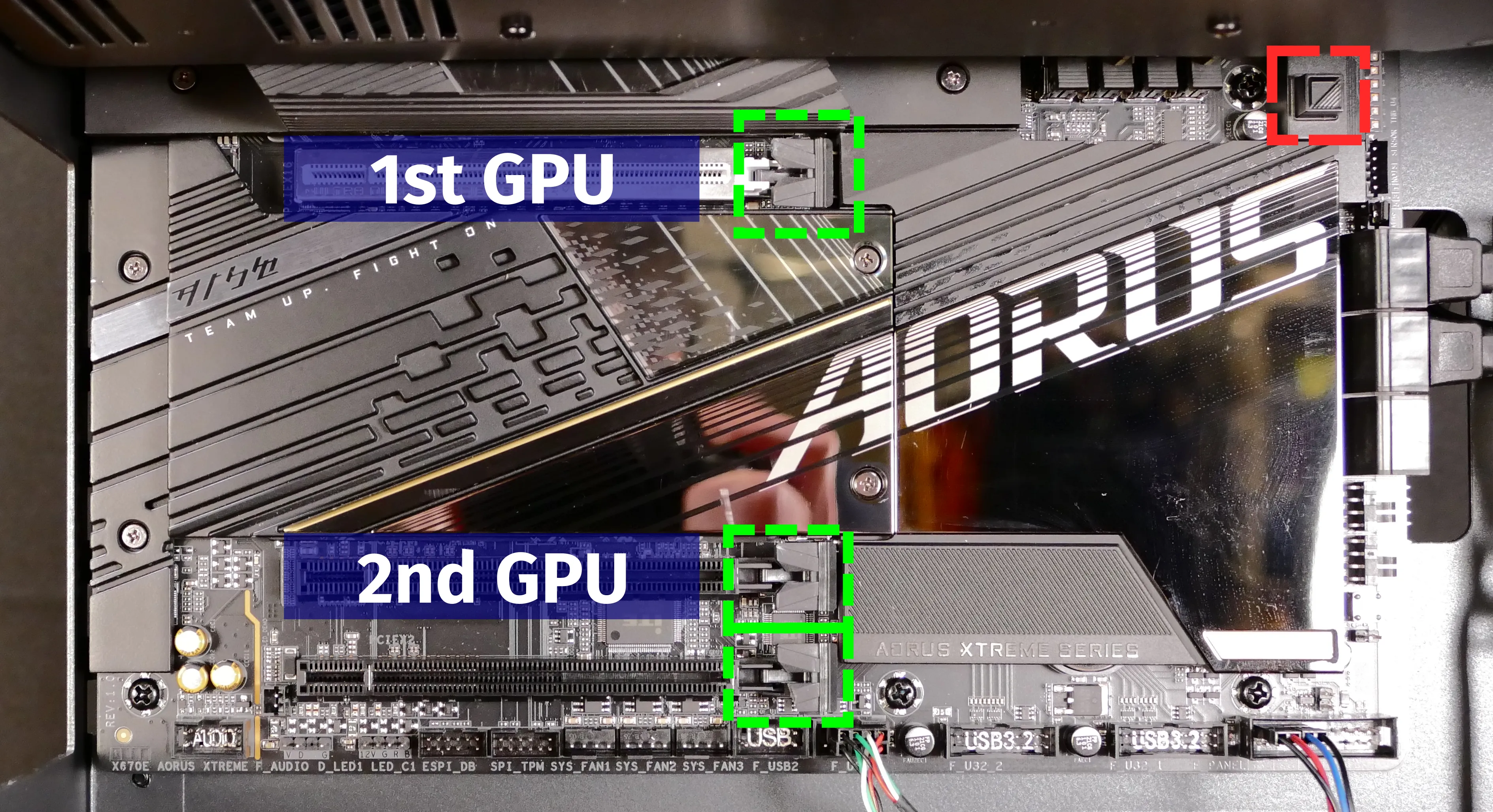
- After inserting the new GPU into its slot, connect the power cable.
- Once the GPU is installed, replace the side GPU brace, back PCIe bracket, and top case.
- The side GPU brace includes screws to adjust for the height and length of the graphics cards.
- The chassis includes multiple sets of screw holes for the side GPU brace to accomodate minor adjustments in graphics card depth; the brace will ship with either short or long GPU fingers (short fingers pictured below), depending on the GPU that was ordered with the machine.

The GPU brace's primary function is to prevent damage during shipping. The system can be run without the brace if it doesn't fit an upgraded card; the back PCIe bracket provides primary support for the GPU.
Replacing the case fans:
Thelio Major R3 has two case-mounted intake fans:
- A 140mm fan on the bottom of the chassis.
- A 92mm fan on the right side of the chassis.
The fans connect to the Thelio-IO board using a Y splitter cable mounted on the inner corner of the case.
Tools required: Cross-head (Phillips) screwdriver
Time estimate: 20 minutes
Difficulty: Medium ●
Steps to replace the bottom case fan:
- Follow the steps above to remove the top case.
- The GPU brace can optionally be removed for easier access to the fans and cables.
- Release the velcro strap and unplug the fan's cable from the Y splitter cable.
- The bottom case fan's cable is round with a mesh net covering.
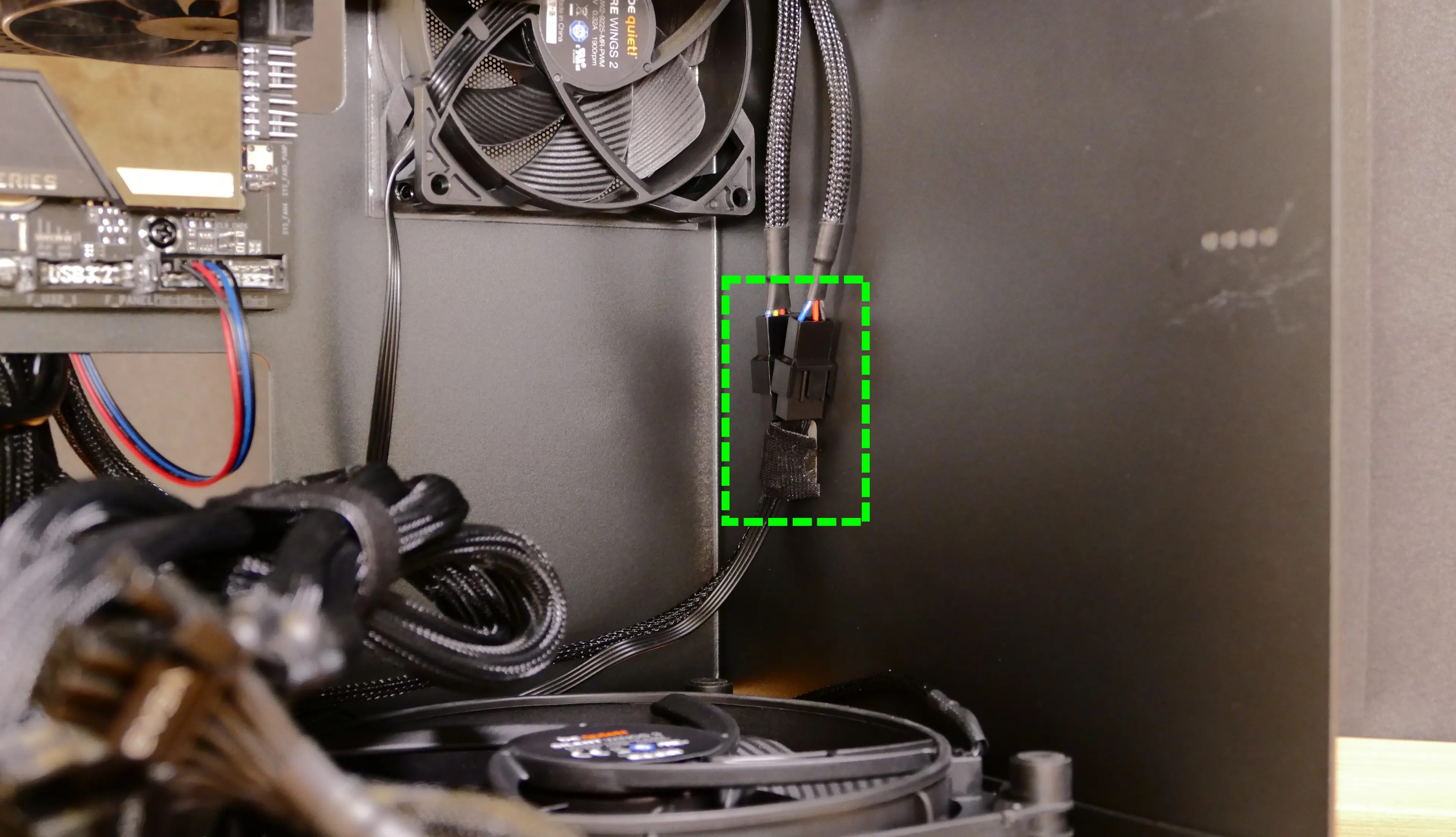
- Unscrew the four fan screws from the bottom of the machine.
- To avoid damaging other components, place the machine on its front side when working with the bottom surface.

- Remove the old fan from the case.
- When installing the fan, mount the components in the following order:
- Chassis
- Dust filter
- Acrylic spacer
- Fan
- The new fan's cable should be oriented towards the front-right corner of the case.
- The cable runs along the inner corner of the case, and does not pass through any of the cable management holes.
Steps to replace the side case fan:
- Follow the steps above to remove the top case.
- The GPU brace can optionally be removed for easier access to the fans and cables.
- Release the velcro strap and unplug the fan's cable from the Y splitter cable.
- The side case fan's cable is flat with four wires.

- Unscrew the four fan screws from the opposite side of the machine.

- Remove the old fan from the case.
- When installing the fan, mount the components in the following order:
- Chassis
- Dust filter
- Acrylic spacer
- Fan
- The new fan's cable should be oriented towards the front-right corner of the case.
- The cable runs along the inner corner of the case, and does not pass through any of the cable management holes.
Removing the CPU duct:
The CPU duct guides airflow through the CPU cooler. It covers the CPU and partially obstructs the RAM slots, top GPU, and spare 2.5" drive screws.
Tools required: Cross-head (Phillips) screwdriver
Time estimate: 7 minutes
Difficulty: Easy ●
Steps to remove the CPU duct:
- Follow the steps above to remove the top case and remove the GPU brace.
- The GPU can also optionally be removed to provide more room for working with the components.
- Unplug the connectors for the CPU fans from the splitter board on the chassis, next to the top right corner of the motherboard.
- The splitter board provides the same signal to both ports, so it doesn't matter which fan is plugged into which port.
- By default, the back fan (long cable) is plugged into the top port (
J2), while the front fan (short cable) is plugged into the bottom port (J3).

- Unscrew the four back thumbscrews and two crossbar screws holding the CPU duct in place.
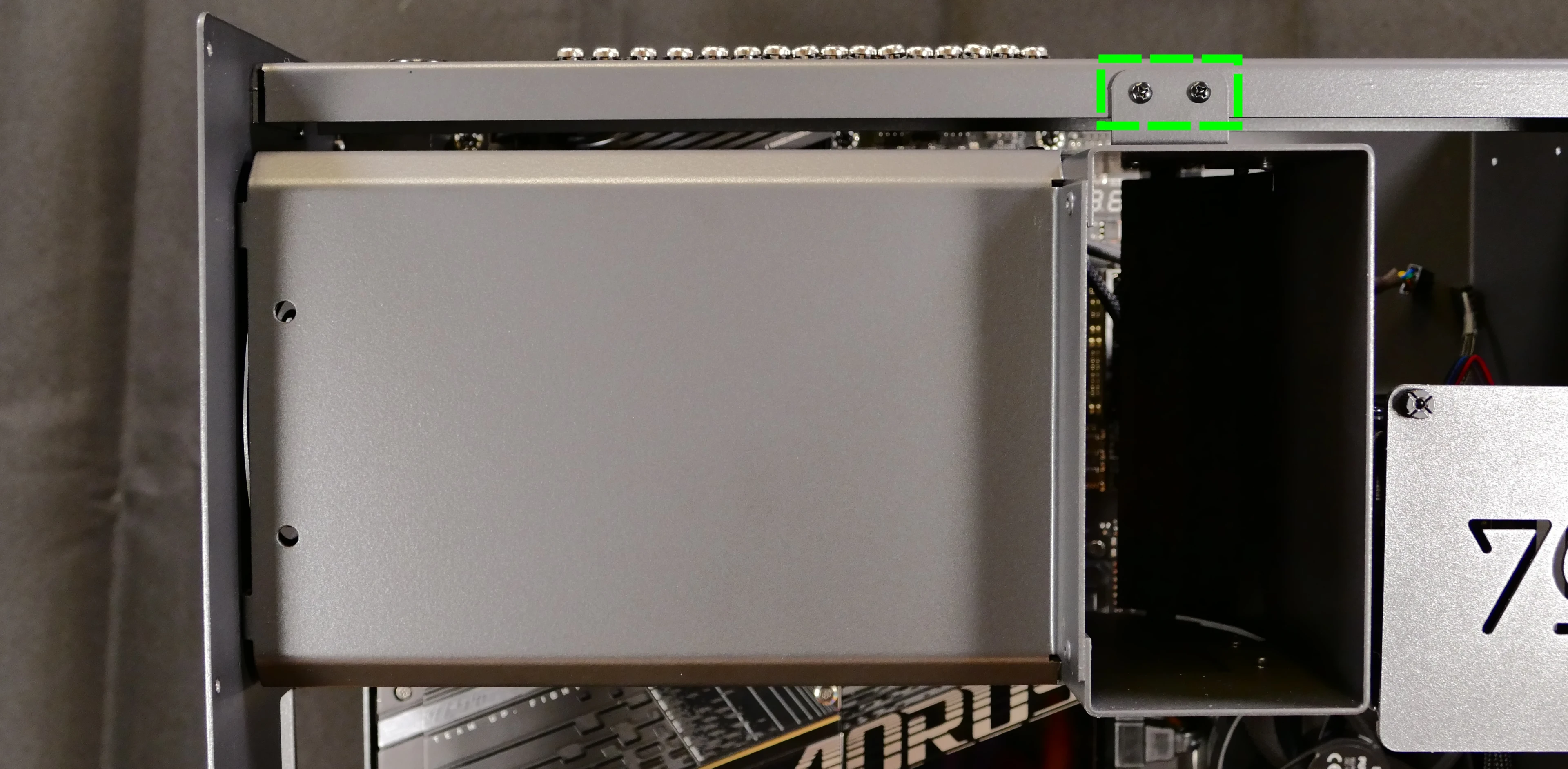
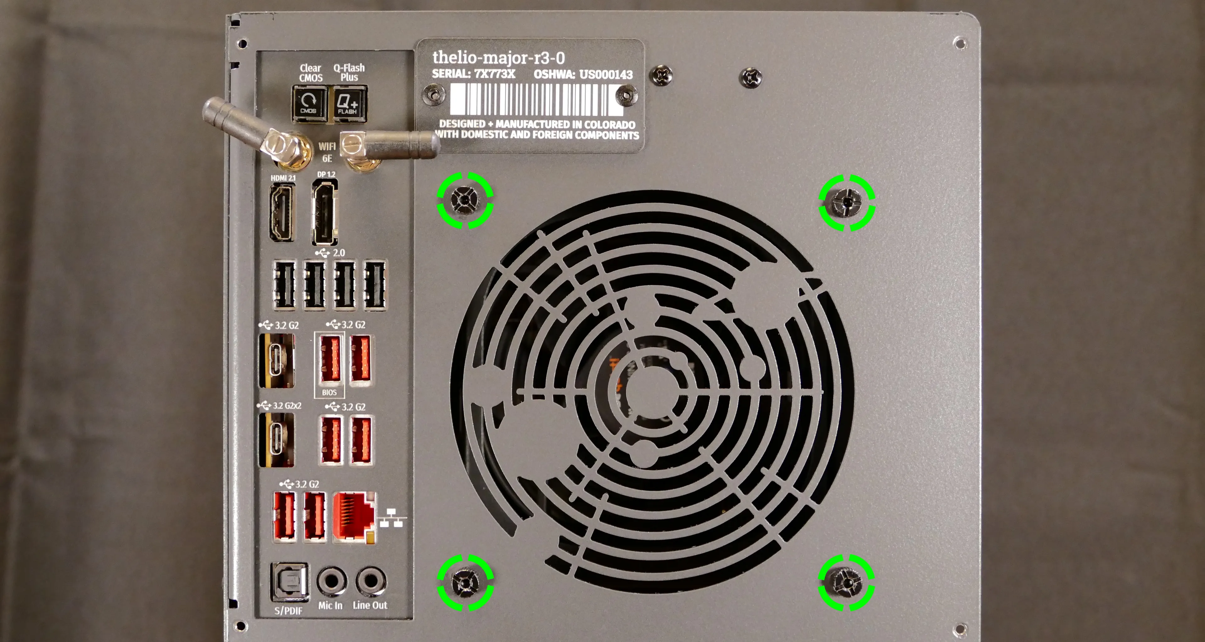
- Pull the CPU duct away from the machine.
Adding/removing 2.5" storage drives:
Thelio Major R3 supports up to four 2.5" SATA III drives.
Tools required: Cross-head (Phillips) screwdriver (optional), flathead screwdriver (optional)
Time estimate: 7 minutes
Difficulty: Easy ●
Steps to add/remove 2.5" storage drives:
- Follow the steps above to remove the top case.
- Unscrew the two screws securing the drive bay's cover, highlighted green below.
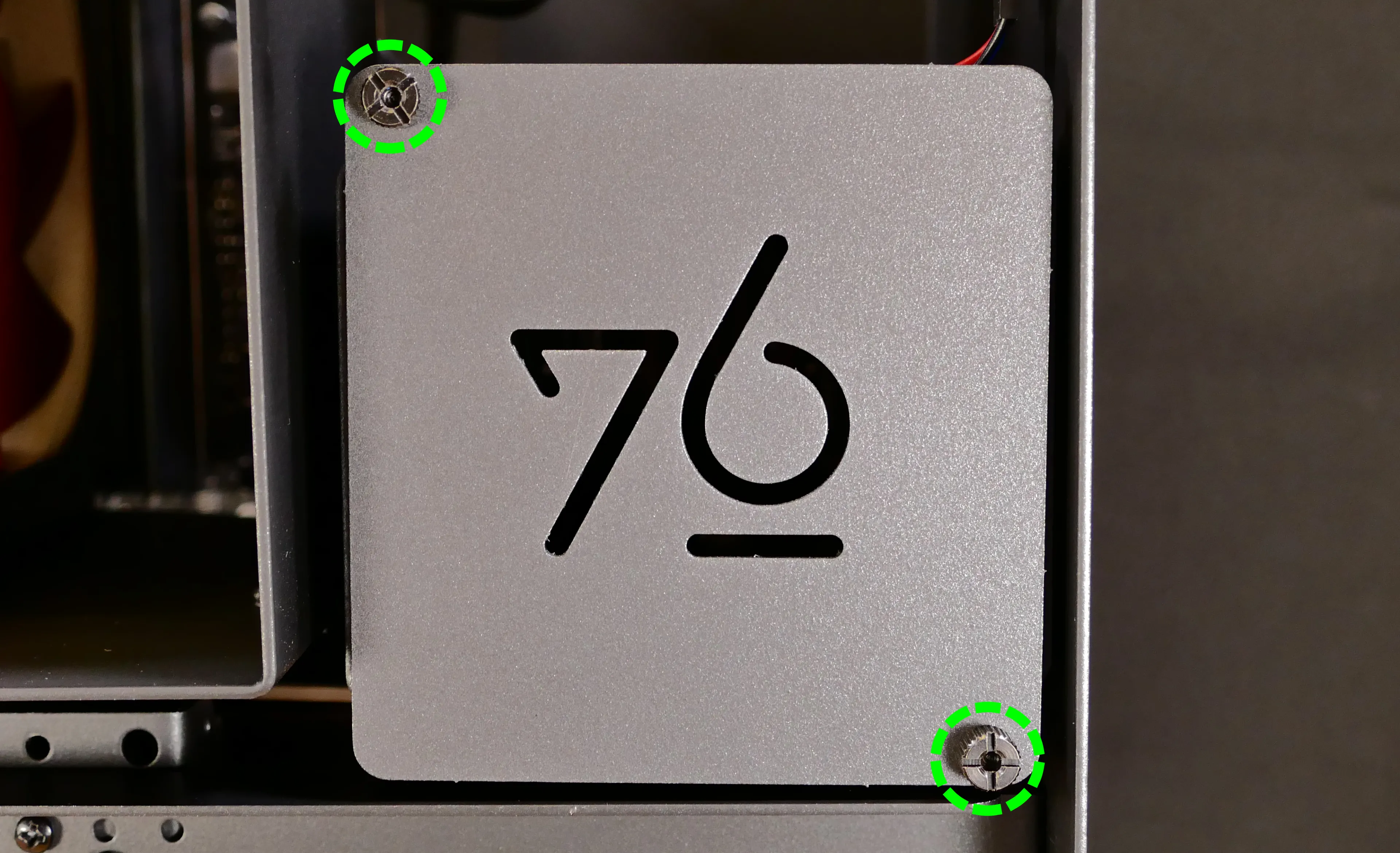
- If you are adding a new drive, pop out the black plastic ring on the top crossbar and slide out four screws (per drive).
- For revisions where the black plastic ring is located over the CPU duct, the ring can be popped out from below using a flathead screwdriver, or by hand after removing the CPU duct.

- Insert four screws into each 2.5" storage drive you wish to install.
- Slide each 2.5" drive into one of the slots leading to the Thelio-IO board.


Thelio Major R3 with one 2.5" drive installed.
- Replace the black plastic screw ring and the 2.5" drive bay cover.
Replacing the RAM:
Thelio Major R3 supports up to 128GB (4x32GB) of RAM. The RAM sticks are DDR5 DIMMs (non-ECC) running at a speed of up to 4800MHz. If you've purchased new RAM, need to replace your RAM, or are reseating your RAM, follow these steps.
Tools required: Cross-head (Phillips) screwdriver
Time estimate: 15 minutes
Difficulty: Medium ●
Steps to replace the RAM:
- Follow the steps above to remove the top case and remove the CPU duct.
- Removing the CPU duct is optional, but is recommended to provide easier access to the RAM slots.
- To remove an existing RAM stick, flip the top and bottom latches away from the stick, then pull the stick out of the slot.

- Make sure the tabs on the top and bottom of the slot are open (pulled away from the slot), then insert the new RAM (or re-seat the existing RAM) into the slot.
- The RAM stick will only fit in one direction. The larger group of pins goes on top.
- Use the following guide for placement of the RAM sticks:

- Replace the top case.
Replacing the M.2 drives:
Thelio Major R3 has four M.2 storage slots. All four slots support PCIe NVMe Gen 5 at x4 bandwidth, sizes 2280 or 25110, and the M key pin arrangement.
M.2 slots 2 and 3 (the bottom two slots) share bandwidth with the PCIe 5.0 x16 slot (the primary GPU slot). If an SSD is installed in M.2 slots 2 or 3, then the PCIe 5.0 x16 slot (the primary GPU slot) will operate at x8 bandwidth. For this reason, M.2 slots 1 and 4 (the top two slots) should be used first.
Tools required: Cross-head (Phillips) screwdriver
Time estimate: 30 minutes
Difficulty: Medium ●
Steps to replace the M.2 drive:
- Follow the steps above to remove the top case and the GPU brace and GPU.
- Unscrew and remove the M.2 heatsink.
- Slot 1 is located underneath the single-height heatsink; slots 2, 3, and 4 are located underneath the triple-height heatsink.
- The heatsink screws are held captive, and will not fully come out of the heatsink.
- It may take some pressure to remove the heatsink and thermal tape from the M.2 drive. After unscrewing the heatsink, pull slowly to avoid breaking the thermal tape.

- For the M.2 drive(s) being removed, push the tab upwards to rotate the circular locking ring; the drive will pop away from the motherboard.

- Remove the existing M.2 drive by pulling it out of the slot.
- Insert the new M.2 drive into the slot; while holding the circular locking ring open, push the drive towards the motherboard.
- While holding the drive in place, let go of the circular locking ring. The ring will rotate back to the closed position.
- Replace the M.2 heatsink, CPU duct, GPU, GPU brace, and top case.
- If you are populating an SSD slot for the first time, remove any protective plastic that may be covering the thermal tape.

Replacing the CPU fans:
Thelio Major R3 contains two CPU fans mounted within the CPU duct. The front fan is a Noctua NF-F12, and the back fan is a Be Quiet! Silent Wings 3.
Tools required: Cross-head (Phillips) screwdriver
Time estimate: 25 minutes
Difficulty: Medium ●
Steps to replace the duct-mounted CPU fans:
- Follow the steps above to remove the top case, remove the GPU brace, and remove the CPU duct.
- For the fan being replaced, unscrew the four screws holding the fan bracket onto the CPU duct.
- The front fan's screws are highlighted yellow; the back fan's screws are highlighted red.

- Unscrew the four screws attaching the bracket to the fan.

- When reinstalling the fans:
- The front fan's spinning side should face the bracket's screws; the back fan's stationary cover should face the bracket's screws.
- The back bracket should face the back of the duct, and the front bracket should face the front of the duct.
- There are two sets of possible screwholes for each bracket; for each bracket, the frontmost set of screwholes (closest to the bent side of the duct) should be used.
- Once installed, both fans should have their spinning sides facing the front of the machine and their stationary covers facing the back of the machine.
- Both cables should be oriented towards the top edge of the motherboard (the top corner of the open side of the duct.)
- Overtightening the fan bracket's screws may cause fan noise; if the fan is creating excessive noise, try slightly loosening some of the screws.
Replacing the CPU cooler and CPU:
The CPU cooler dissipates heat from the CPU to the heatsink, where the CPU fans expel it from the system. Depending on your climate and the age of the machine, replacing the thermal paste between the CPU and the cooler/heatsink may help the system run cooler.
The CPU uses an AMD AM5 socket. The CPU cooler is a Noctua NH-U12S.
Tools required: Cross-head (Phillips) screwdriver, thermal paste
Time estimate: 45 minutes
Difficulty: High ●
Steps to remove the CPU cooler/thermal paste:
- Follow the steps above to remove the top case, remove the GPU brace and GPU, and remove the CPU duct.
- While holding the CPU cooler in place so it doesn't fall, unscrew the two screws holding the CPU cooler crossbar onto the vertical mounting brackets.
- The screws are held captive, and will not fully come out of the crossbar.
- Only the two outer screws need to be removed; the center screw holding the horizontal crossbar onto the heatsink does not need to be removed.

- The cooler will come away from the CPU.
- Using a paper towel, clean the existing thermal paste off of the heatsink and CPU. You may also use a small amount of rubbing alcohol if the old paste is dried or difficult to remove.

Steps to replace the CPU:
- Place the computer on its side so the motherboard is facing up.
- Unscrew and remove the cooler mounting bracket on the right side of the CPU.

- Push the locking pin outward until it's able to spring away from the motherboard.
- Caution: the locking pin may spring up with significant force when freed.

- Flip the CPU holder away from the CPU.
- The CPU holder opens in the opposite direction from the locking pin.

- Carefully lift the CPU out of the CPU socket.
- Be careful not to bend any of the gold pins on the CPU socket, and do not touch the gold pads on the CPU.

- Gently place the new CPU into the socket.
- The triangle on the CPU should be oriented to match the triangle on the CPU cover, pointing towards the top left of the motherboard.
- Flip the CPU cover back onto the CPU and push the locking pin down into place.
- Reinstall the right-side cooler mounting bracket.
Steps to install the thermal paste/CPU cooler:
- Draw an
Xshape of thermal paste onto the CPU.

- Place the CPU cooler onto the CPU; while holding it in place, screw each end of the cooler crossbar onto one of the mounting brackets.
- The cooler should be oriented so the text is readable from the right side (front of the case).
- Insert each screw partially first, then fully tighten both.
- Set the computer upright, then reinstall the cooler-mounted CPU fan, CPU duct, GPU, GPU bracket, and top case.
Replacing the power supply:
The power supply unit (PSU) is modular and can be replaced with another unit of the same model. Different models may not be compatible with the pre-installed cabling.
Tools required: Cross-head (Phillips) screwdriver
Time estimate: 20 minutes
Difficulty: Medium ●
Steps to replace the power supply:
- Follow the steps above to remove the top case and remove the GPU brace and bottom GPU.
- Unplug all of the modular cabling from the back of the PSU.
- Some of the cables may be easier to unplug after the PSU has been unscrewed/removed from the case.

- Unscrew and remove the PSU bracket.
- One screw is located on the opposite side of the case.
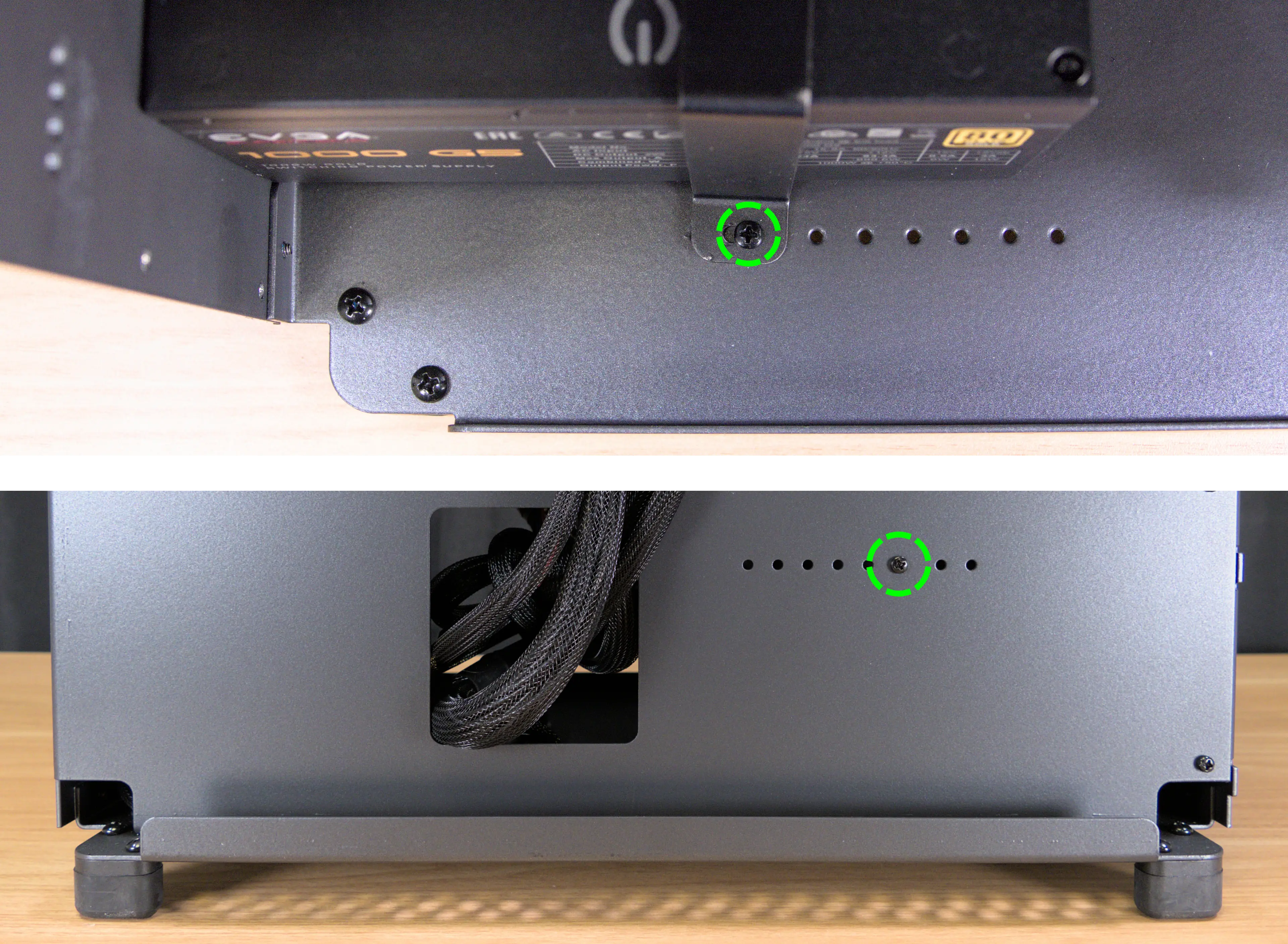
- Unscrew the four screws holding the PSU in from the back of the case.

- Remove/replace the PSU.
- Set the replacement PSU on top of the rubber post that holds it at the correct height.
- The replacement PSU should be installed with the fan facing the bottom of the case.

- After screwing in the replacement PSU, use the labels and pin counts on the cables and ports to ensure the power cables are reconnected in the proper locations.
- Remember that not all of the available connectors will plug into the PSU-- two 8-pin (6 + 1) connectors are to be plugged into the GPUs.
- If the replacement PSU has an
ECOswitch, make sure it is switched on for an optimal fan curve.
Replacing the Thelio-IO board:
Tools required: Cross-head (Phillips) screwdriver
Time estimate: 25 minutes
Difficulty: High ●
The Thelio-IO board handles the front power button, fan control, and 2.5" SATA connectors for the system. If the Thelio-IO board becomes defective, it can be replaced using the instructions below.
Steps to replace the Thelio-IO board:
- Follow the steps above to remove the top case and remove the 2.5" drive cage cover and any 2.5" drives that are installed.
- Use the cutouts on the front right corner of the chassis to unplug all cabling from the Thelio-IO board.
- The topmost connector requires pulling the white tab while unplugging.

- Unscrew the two screws on the top side of the drive cage.

- While pulling the loose side of the drive cage away from the Thelio-IO board, move the board back and out of the drive cage.
- Place the new Thelio-IO board into the drive cage and replace the screws and wiring.
Thelio-IO wiring guide:

- When wiring the Thelio-IO board, refer to the above image and the following guide. The ports are numbered in the suggested connection order based on position and size.
- 1:
POWER0- to the power supplyPERIFport (via 4-pin Molex adapter.) - 2:
INTAKE0- to the case fans (via a Y splitter cable). - 3:
CPUOUT0- to the splitter board (near the top edge) connecting to both duct-mounted CPU fans. - 4:
CPUIN0- to theCPU_FANheader at the top of the motherboard.
- 5:
DATA0/1/2/3- to SATA ports #0/#1/#2/#3 on the motherboard, highlighted green below.- The ports are located next to the top GPU slot.
- These connectors provide data transfer for the 2.5" drive slots.
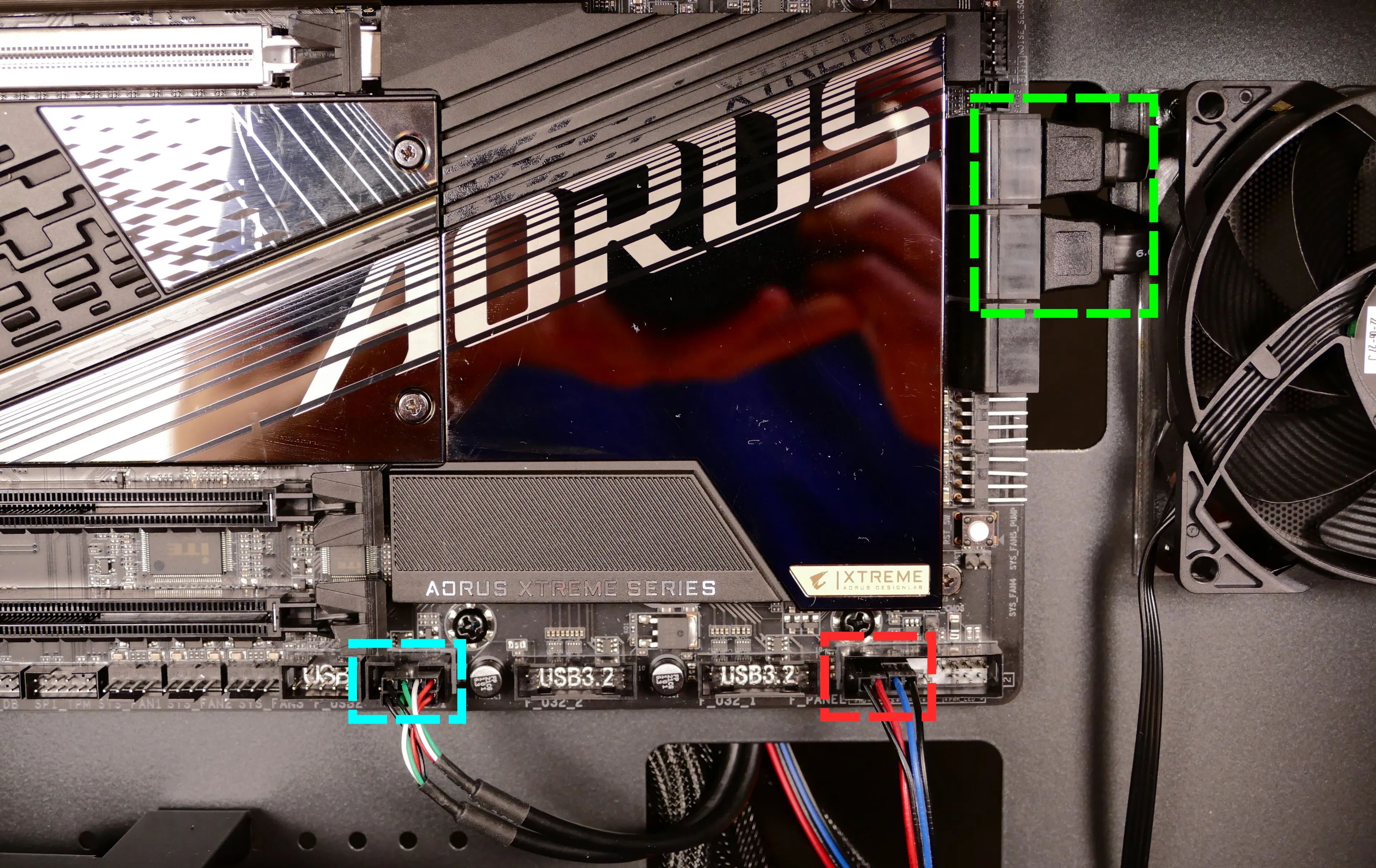
- 6*:
PFP0- to the power button receptacle on the front panel. - 7*:
USB0- to theF_USB1header on motherboard, highlighted cyan above.
- On the Thelio-IO board, the row of four pins plugs in, while the row of five pins hangs off the back and does not plug in.
- This connector provides fan control and firmware updates.
- 8*:
PMB0- to the+PLED-and+PW-pins (the four top-left pins of theF_PANELheader) on the motherboard, highlighted red above.- On the motherboard, the red wire goes on the inner-left and the blue wire goes on the inner-right. The corresponding black wires go on the outer-left and outer-right.
- * For all connectors with multi-colored wires plugging into the Thelio-IO board, the red wire goes on the top side (viewing from the front of the computer.)
- 1:
Troubleshooting the power button:
If the front power button doesn't power the machine on or doesn't light up when the system is powered on, try the following troubleshooting steps:
- Ensure the system powers on normally using the internal power button.
- Reseat the front power button to ensure it's making proper contact.
- Check the wiring for the front power button.
- Replace the front power button, if necessary.
Tools required: Cross-head (Phillips) screwdriver (optional)
Time estimate: 20 minutes
Difficulty: Medium ●
Steps to power the machine on using the internal power button:
- Follow the steps above to remove the top case.
- Ensure the system is plugged into power, and the power supply switch is in the 1 (On) position.
- Push the small button labeled
B0on the Thelio-IO board.

- If the Thelio-IO
B0button powers the machine on, then the issue is either the front power button or its connection to the Thelio-IO board. Check the front power button wiring. - If the Thelio-IO
B0button does not work, then the issue is either the Thelio-IO board or its connection to the motherboard. Check the wiring between the Thelio-IO board and the motherboard.
Steps to check the front power button wiring:
- Follow the steps above to remove the top case.
- On the back of the power button, the four pins should be connected to the four-wire connector as follows:

- On the front power button receptacle, the four-pin connector should have the red wire on the left and the black wire on the right (when viewed from the back of the computer.)

- The front power button receptacle should plug into the
PFPDport on the Thelio-IO board, with the red wire on the top (see the Thelio-IO wiring guide.)
Steps to replace the power button:
- Follow the steps above to remove the top case.
- Follow the instructions in the Replace the Thelio Power Button support article.
Thelio Major B2
Tech Specs
Processor
Intel® Core™ X series
Graphics
Up to 2× AMD® or NVIDIA® Graphics
Video Ports (Dependent on GPU selection):
-
Radeon RX 550: 1× DisplayPort, 1× HDMI, 1× DVI
-
Radeon RX 590: 3× DisplayPort, 1× HDMI
-
Radeon RX 5700: 3× DisplayPort, 1× HDMI
-
Radeon RX 5700 XT: 3× DisplayPort, 1× HDMI
-
RX Vega 64: 3× DisplayPort, 1× HDMI
-
GeForce RTX 2060 Super: 3× DisplayPort, 1× HDMI
-
GeForce RTX 2070 Super: 3× DisplayPort, 1× HDMI, 1× USB Type-C
-
GeForce RTX 2080 Super: 3× DisplayPort, 1× HDMI, 1× USB Type-C
-
GeForce RTX 2080Ti: × DisplayPort, 1× HDMI, 1× USB Type-C
-
RTX Titan: 3× DisplayPort, 1× HDMI, 1× USB Type-C
Memory
Up to 256 GB Quad Channel DDR4
Storage
Up to 46 TB, M.2 NVMe and 2.5″ SATA drives
Rear Ports
- 1× USB 3.1 Type C
- 1× USB3.1 Gen 2 Type A (red)
- 6× USB 3.1 Gen 1
- 1× RJ-45 Port (Ethernet)
Rear Audio
6× auido jacks (Center/Subwoofer Speaker Out, Rear Speaker Out, Side Speaker Out, Line In, Line Out, Mic In)
Networking
- Gigabit Ethernet
- Optional Intel® Wireless-AC (a/b/g/n/ac) with Bluetooth
Power Supply
- 1000W 80+ Certified (90% or greater power efficiency)
- C13 power cord
Dimensions
Height × Width × Depth
18.19″ × 10.32″ × 16.06″ (462 × 262 × 408mm)
Model
thelio-major-b2
Thelio Major R2
Tech Specs
Processor
AMD® 3rd Gen Ryzen™ Threadripper™ series
Graphics
Up to 2 x AMD® or NVIDIA® Graphics
Video Ports (Dependent on GPU selection):
Radeon RX 550: 1× DisplayPort, 1× HDMI, 1× DVI
Radeon RX 5700: 3× DisplayPort, 1× HDMI
Radeon RX 5700 XT: 3× DisplayPort, 1× HDMI
GeForce RTX 2060 Super: 3× DisplayPort, 1× HDMI
GeForce RTX 2070 Super: 3× DisplayPort, 1× HDMI, 1× USB Type-C
GeForce RTX 2080 Super: 3× DisplayPort, 1× HDMI, 1× USB Type-C
GeForce RTX 2080Ti: 3 × DisplayPort, 1× HDMI, 1× USB Type-C
RTX Titan: 3× DisplayPort, 1× HDMI, 1× USB Type-C
Memory
Up to 256 GB Quad Channel DDR4 @ 3000 MHz
Storage
Up to 46 TB, M.2 NVMe and 2.5″ SATA drives
Rear Ports
- 5 x USB 3.2 Gen 2 Type-A (red)
- 4 x USB 2.0
- 1 x USB 3.2 Gen 2 Type-C
- 1 x RJ-45 LAN
Rear Audio
5 x Audio Jacks
Networking
Gigabit Ethernet w/ built-in Intel® Wireless-AC (a/b/g/n/ac/ax) with Bluetooth 5.0
Power Supply
1000W 80+ Certified (90% or greater power efficiency)
Dimensions
Height × Width × Depth
18.19″ × 10.32″ × 16.06″ (462 × 262 × 408mm)
Model
thelio-major-r2
External Overview
Ports Overview
Your Thelio Major has several ports accessible from the rear of the machine.
Thelio Major B2 (Intel):
- 4 USB 3.1 Gen 1 Ports
- 4 USB 3.1 Gen 2 Ports
- 1 USB 3.1 Gen 1 Type-C
- 1 RJ45 Ethernet port
- Audio In/Out ports (3.5mm, plus TOSLink S/PDIF)
- 1 Standard 3-prong AC wall adapter port connected to the power supply (with power switch).

Fig. 1: External Thelio Major ports overview.
Thelio Major R2 (AMD):
- 4 USB 2.0 Type-A
- 1 USB 3.2 Gen 2 Type-C
- 5 USB 3.2 Gen 2 Type-A
- 1 RJ45 Ethernet port
- Audio In/Out ports (3.5mm, plus TOSLink S/PDIF)
- Audio In/Out ports (3.5mm, plus TOSLink S/PDIF)

Connecting Displays
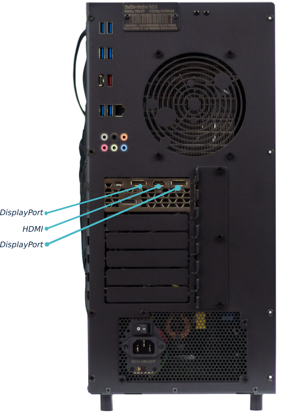
Fig. 2: Thelio Major external display ports overview.
Ports will differ from the above image, depending on which graphics cards you have installed.
Since neither Threadripper or Intel Core X processors have integrated graphics, a discrete graphics card is required to use displays on your Thelio Major.
Internal Overview
Thelio Major B1
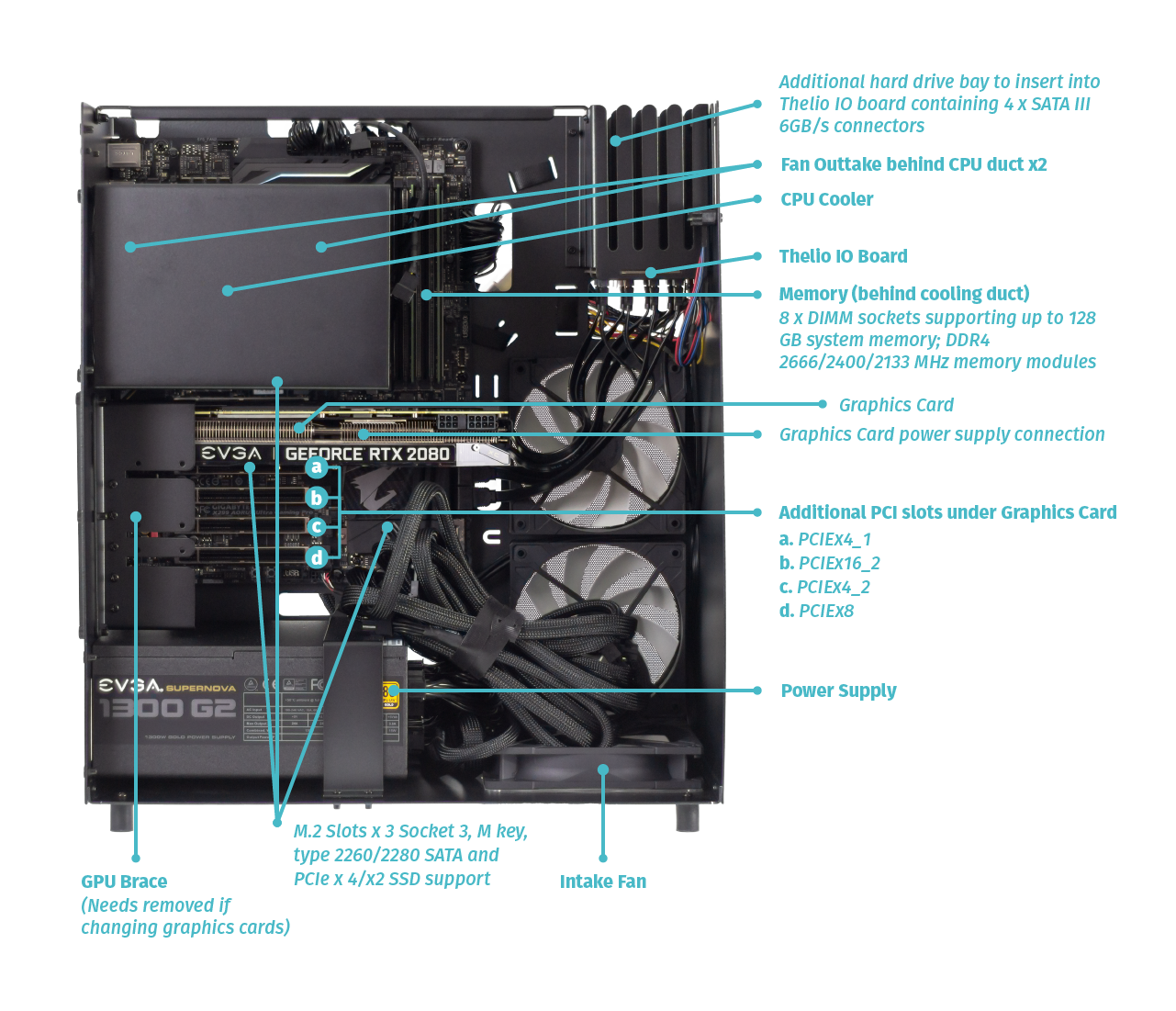
Thelio Major B2

Thelio Major R1

Thelio Major R2

Power Switch Connections Overview
The Thelio power button is wired as in the diagram and photo.
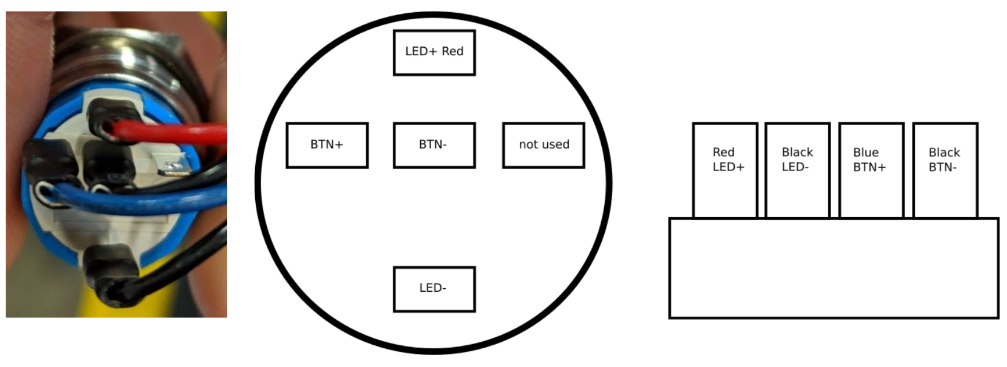
Fig. 12: Close up of Thelio power switch wiring (left). Thelio power switch Wiring Diagram (right).
Thelio IO Board
USB IO The USB connector has a row of 5 and a row of 4 holes for pins. You want to use the row of 4 holes with the red wire to the left. For reference, this is the pinout:
| 5V | D- | D+ | GND | None |
|---|
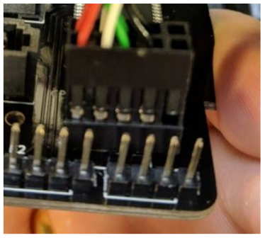
Fig. 13: Thelio IO Board Pinout.
IO Power button
The button is connected to the left side and the motherboard on the right. Both are connected with the solid plastic side facing the edge. This is the pinout:
| Button | LED+ | LED- | BTN+ | BTN- |
|---|---|---|---|---|
| Board | LED+ | LED- | BTN+ | BTN- |
Fig. 14: Power Button and Motherboard power connectors attached to Thelio IO board.
Fig. 15: Thelio internal power switch (underside of the Thelio IO board).
The Thelio IO power button can be used to power on the Thelio when the top case is removed. The button is located on the underside of the Thelio IO Board (Fig. 15, above).
Motherboard Power button
The motherboard power button is connected on the part of the front panel header missing a pin. Due to a design oddity of motherboards used for Thelio, the positive and negative power button lines must be flipped.
Fig. 16: Motherboard power button and Thelio Power Button connections.
This is the pinout:
| LED- | LED+ | BTN+ | BTN- | None |
|---|
Table of Contents
Thelio Major B2 BIOS Overview
BIOS
User Serviceable Parts and Repairs
Top Case (Remove or Replace)
Power Button (Remove or Replace)
CPU Cooler Duct (Remove or Replace)
RAM (Remove or Replace)
GPU (Remove or Replace)
Drives (Remove or Replace)
CPU Thermal Paste (Remove or Replace)
BIOS
Thelio systems ship with the BIOS configured to the preferred settings. For example, OSes are installed on Thelio systems in UEFI mode by default. It is not necessary to change any of these BIOS settings, however the BIOS menus are shown here for reference.
Hardware Keyboard Shortcuts:
F12 : Boot Menu
F9 : System Information
ESC : BIOS
END : Q-Flash
M.I.T
Fig. 1: The M.I.T. page allows tweaking the frequency of some system components.
System
Fig. 2: System summary in BIOS.
BIOS Menu
Fig. 3: BIOS boot summary.
Peripherals
Fig. 4: BIOS section for Peripheral setup.
Chipset
Fig. 5: Chipset information in Thelio BIOS.
Power
Fig. 6: Power Management settings.
Save and Exit
Fig. 7: Exit the BIOS saving changes to settings.
Top Case (Remove or replace)
Removing the Top Case
Before servicing your Thelio, be sure to power off and unplug all cords from the computer.
You can find video instructions on this process here.
Tools required: Fingers or Cross-head (Phillips) screwdriver
Time estimate: 2 minutes
Difficulty: Easy
Screws: 8 total
- 8 Thumbscrews (Phillips/Cross-head).
Note: These thumbscrews will be on the top left and right, middle left and right, and bottom left and right of the back of the case.
Do not unscrew any screws in the center of the panel. Those screws correspond with parts inside; removing them will not assist you in removing the lid.
All of Thelio’s thumbscrews are the same size, and are interchangeable.
- Unscrew the eight (8) thumbscrews from the back of the Thelio.
- Lift the lid up and off of the chassis.
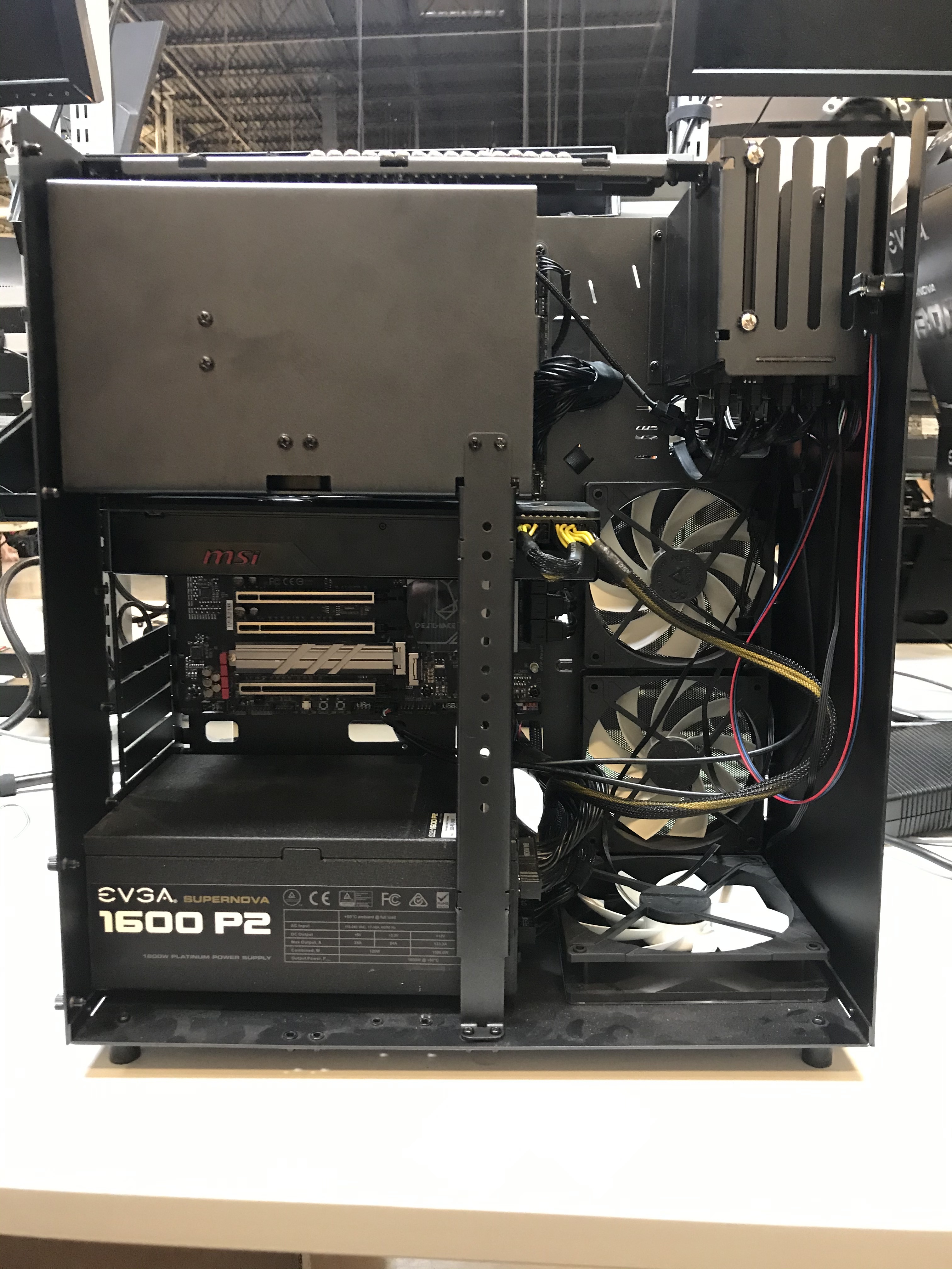
Fig. 10: Thelio internals with Top Case completely removed.
Replacing the Top Case
This guide explains how to replace the Thelio’s Top Case after performing maintenance.
Tools required: Fingers or Crosshead (Phillips) screwdriver
Time estimate: 2 minutes
Difficulty: Easy
Screws: 8 total
- 8 Thumbscrews (Phillips/Crosshead).
- Align the grooves inside the case with the front of the Thelio frame (the side where the power-button is located).
- Once aligned, the case should easily slide down over the chassis.
- Press down on the Top Case to make sure it is firmly seated, and the power button is connected internally. There should be no space between the bottom of the Top Case and the Thelio frame.
- To ensure the case is seated correctly, plug the Thelio back into power, turn on the power-supply switch, and examine the front of the unit: the power button LED should light up if you press it, and the system fans should spin to life.
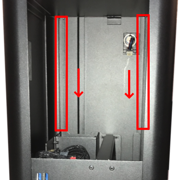
Fig. 11: Aligning the Thelio Top Case for replacment. A Thelio (non-major) is pictured here, but the alignment process is the same.
Power Button (Remove or Replace)
If you’ve purchased a new top case for your Thelio (or received one for a support case), you may need to move the power button from your old top case to the new one. Conversely, if you’ve received a replacement power button, you may need to remove the old power button from your top case and install the new one.
Removing the Power Button
The power button assembly is held on by a single nut inside the case.
Tools required: Needle-nose pliers.
Time estimate: 5 minutes
Difficulty: Easy
- Follow the steps to remove the top case
- Unplug the power button’s wire from the 90-degree connector (Fig. 12).
- Next, unscrew the nut from the power button. Use a pair of needle-nose pliers to loosen the nut (Fig. 14).
- Once the nut has been loosened, use your fingers to remove it the rest of the way (Fig. 15).
- With the wire unplugged and the nut removed, the power button can be pushed out the front of the case (Fig. 17).
- The black plastic rectangle inside of the case will also be loose at this point, and can be removed.
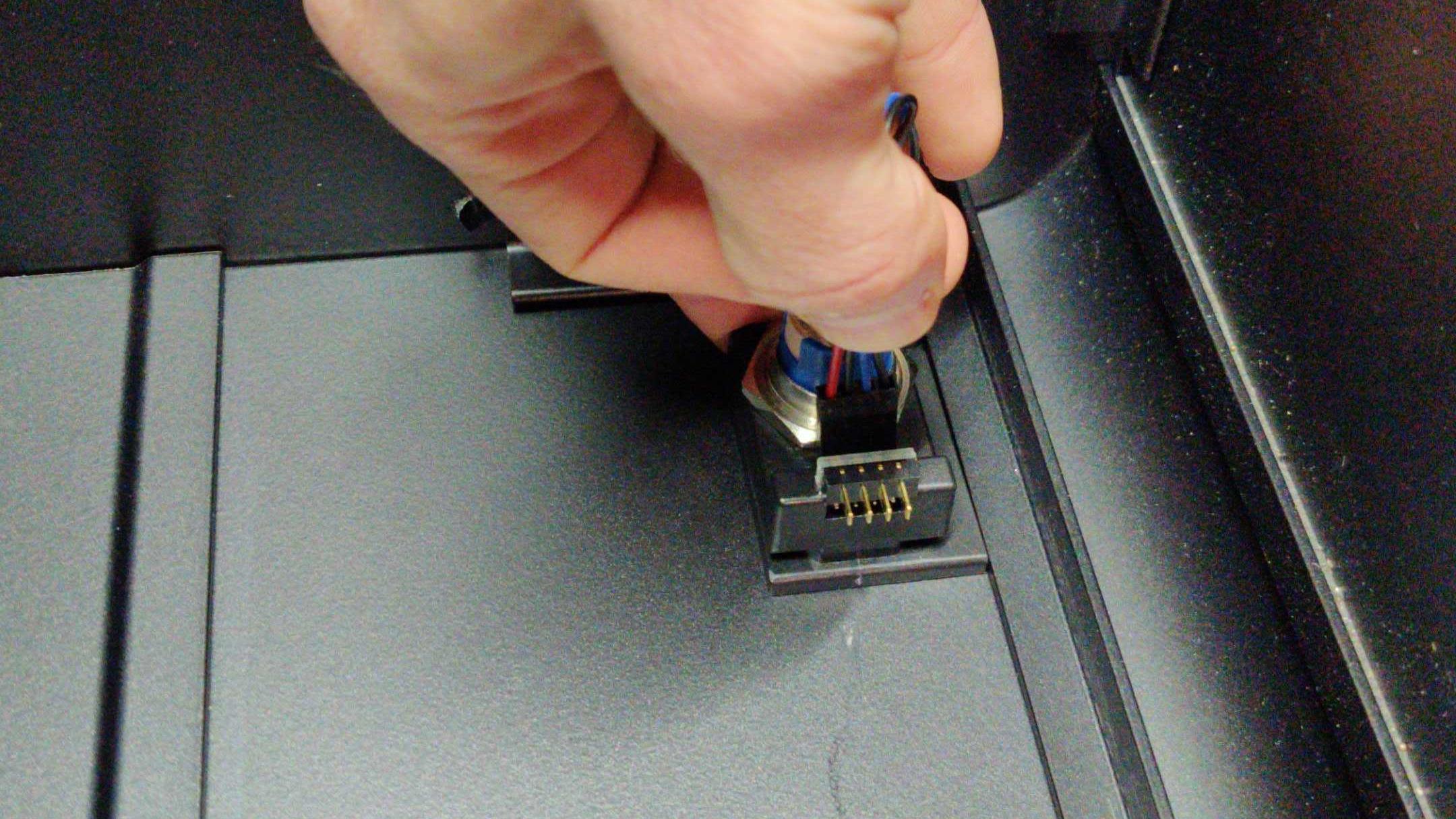
Fig. 12: Unplugging power button from 90-degree connector.
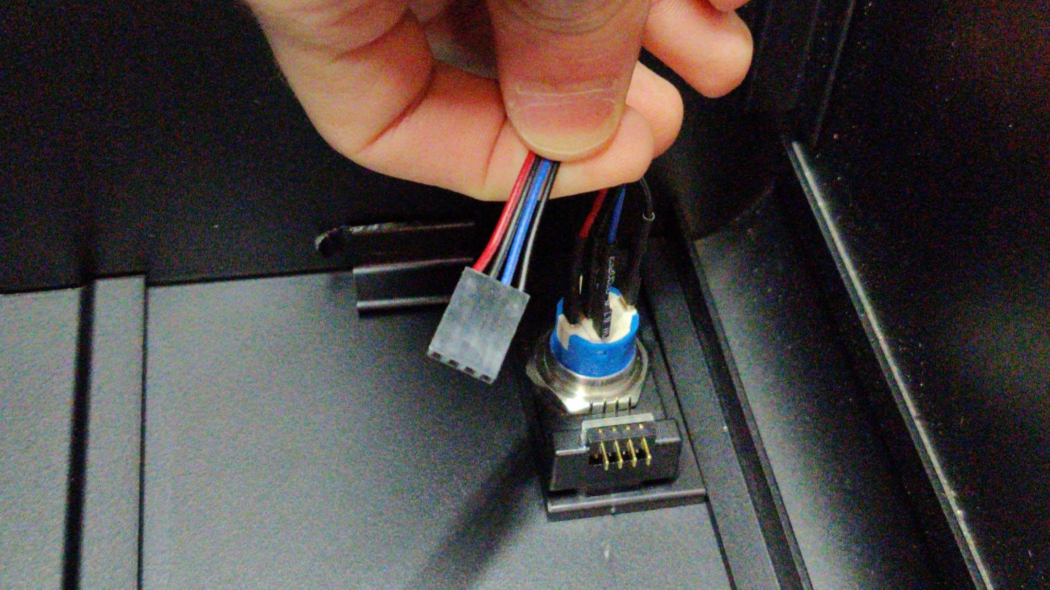
Fig. 13: Cable disconnected from 90-degree connector.
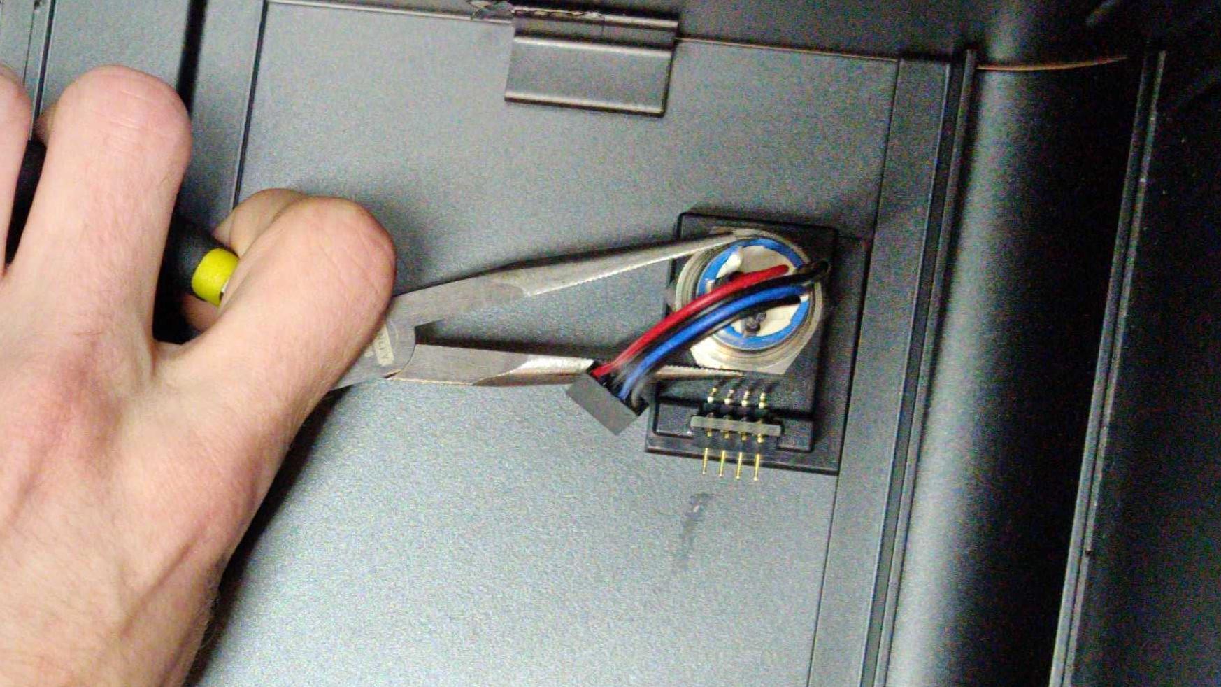
Fig. 14: Needle-nose pliers can help with unscrewing the nut.
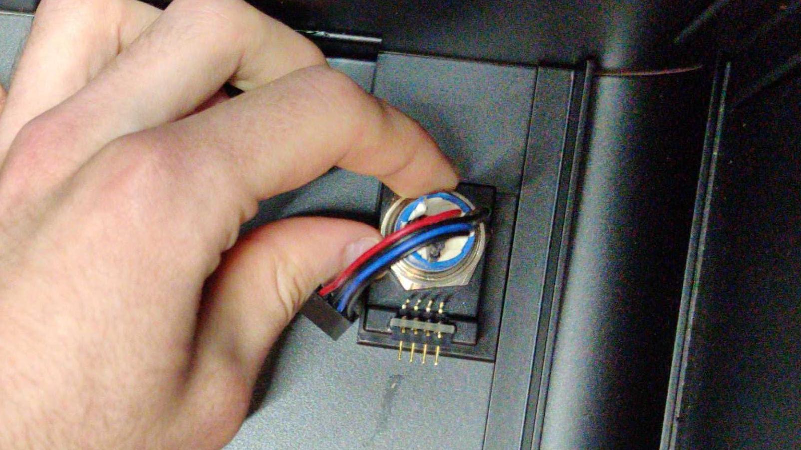
Fig. 15: Once loose, the nut can be unscrewed with fingers.
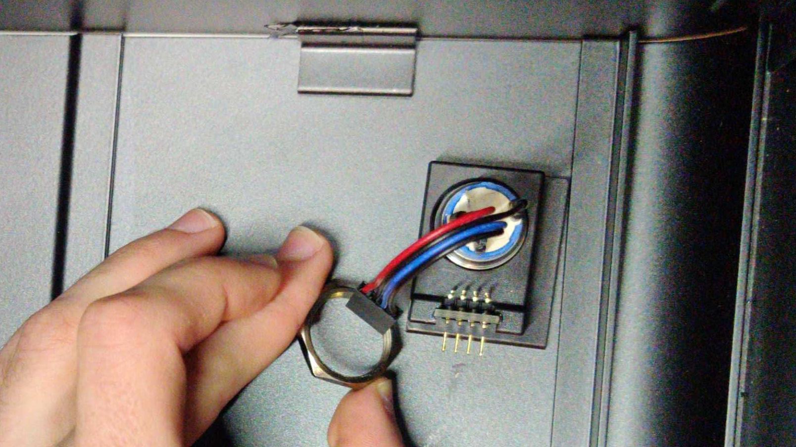
Fig. 16: Removing the nut.
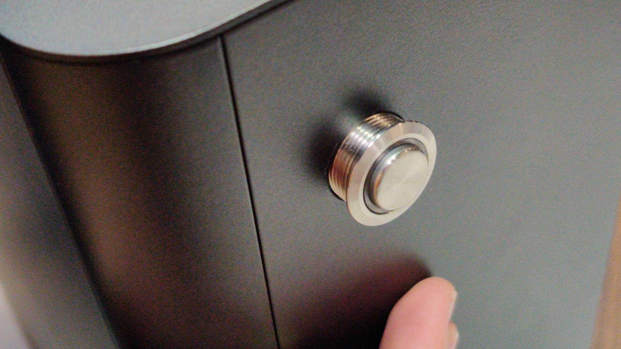
Fig. 17: Once the nut is removed, push the power button through the hole in the Top Case.
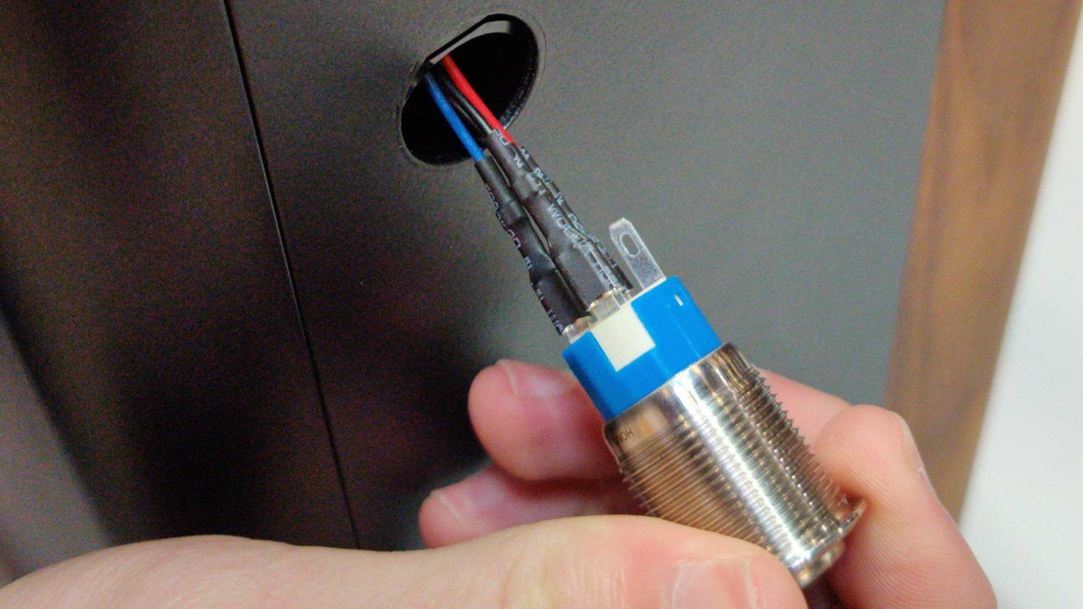
Fig. 18: Power being pulled completely through Top Case.
Replacing the Power Button
Tools required: Needle-nose pliers.
Time estimate: 5 minutes
Difficulty: Easy
- Line up the black plastic rectangle with the hole inside of the case (Fig. 20).
- While holding the black plastic rectangle to the hole, feed the power button wire through the hole and push the power button into the case (Fig. 21).
- While holding the button in from the front, thread the power button wire through the nut, then screw the nut onto the power button (Fig. 24).
- Tighten the nut with a pair of needle-nose pliers to ensure the plastic bracket doesn’t move around later (Fig. 26).
- Finally, plug the power button’s wire into the 90-degree connector so the red wire is on the left (Fig. 27).
- Follow the steps to replace the top case
Fig. 19: The empty power button hole in the Top Case.
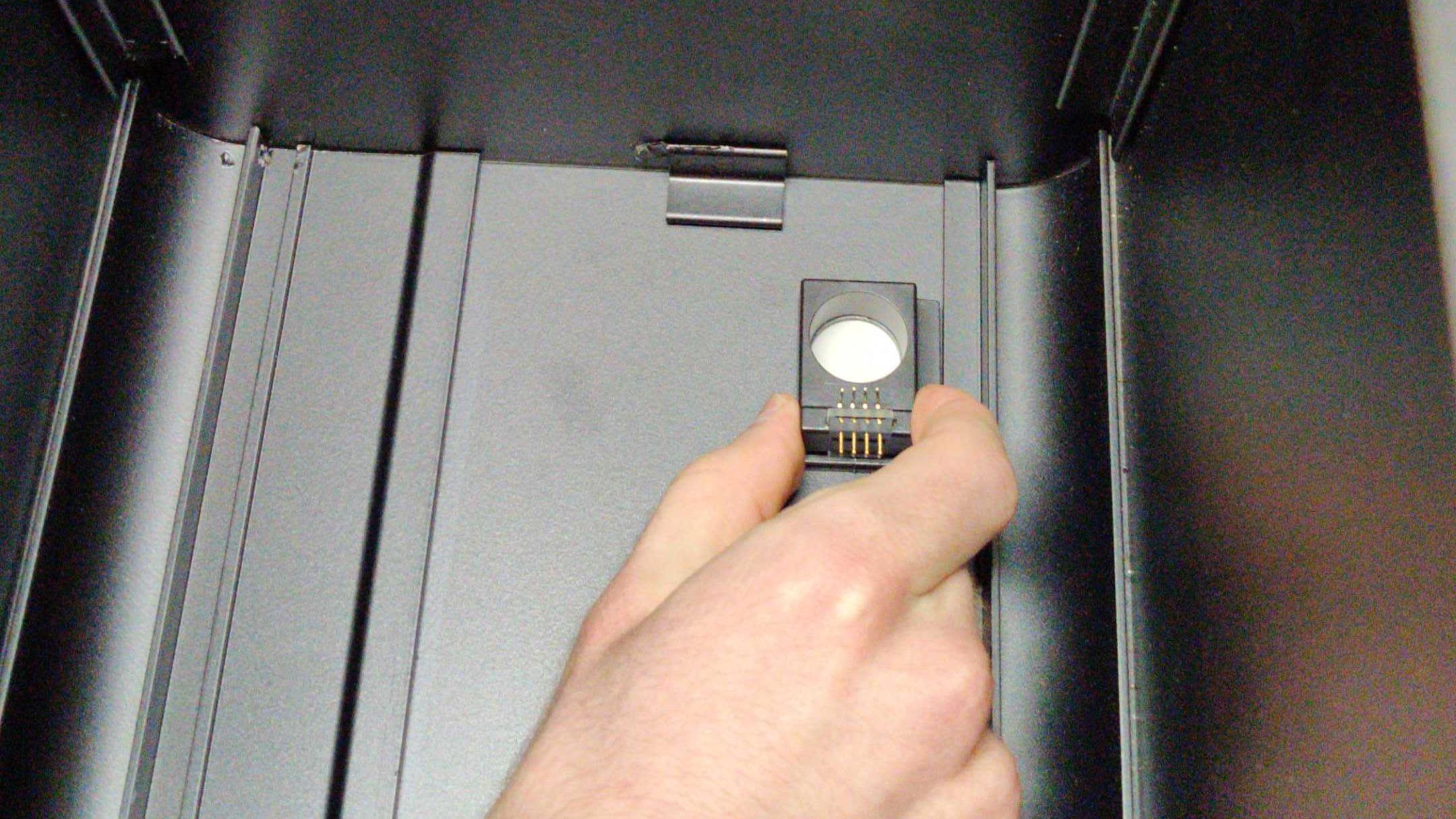
Fig. 20: Aligning the internal bracket.
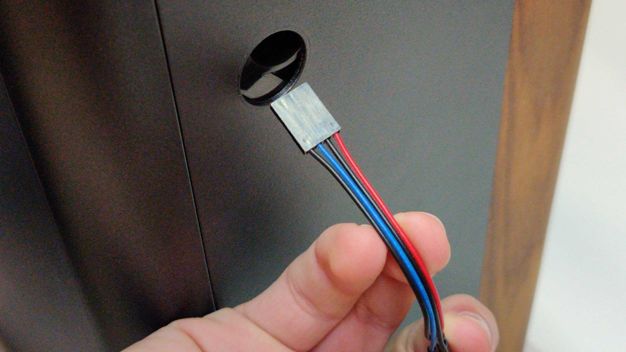
Fig. 21: Inserting power button cables.
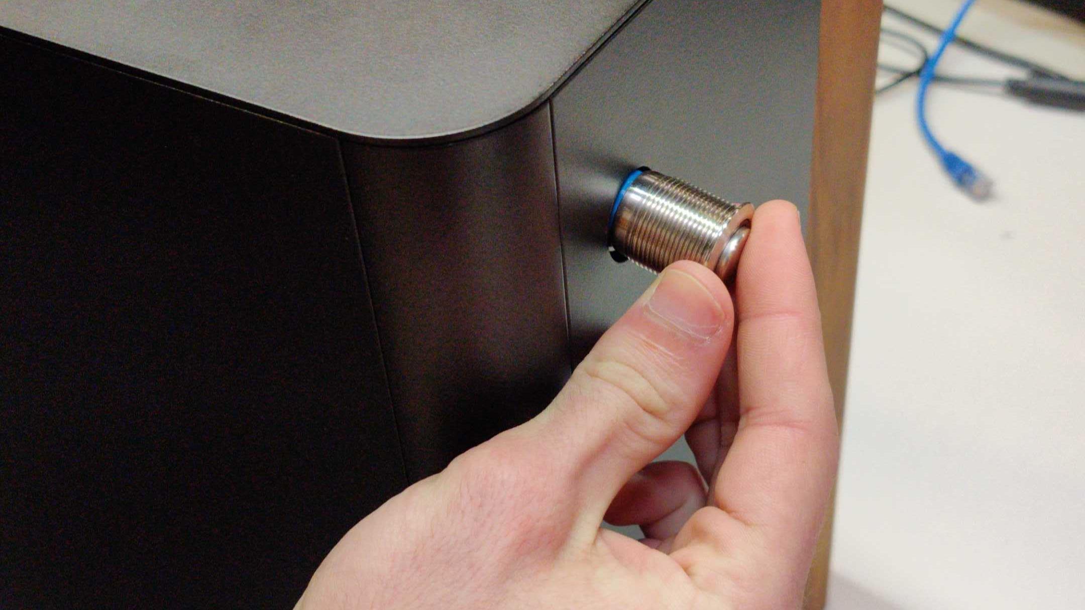
Fig. 22: Inserting power button through Top Case.
Fig. 23: Power button fully inserted in the Top Case.
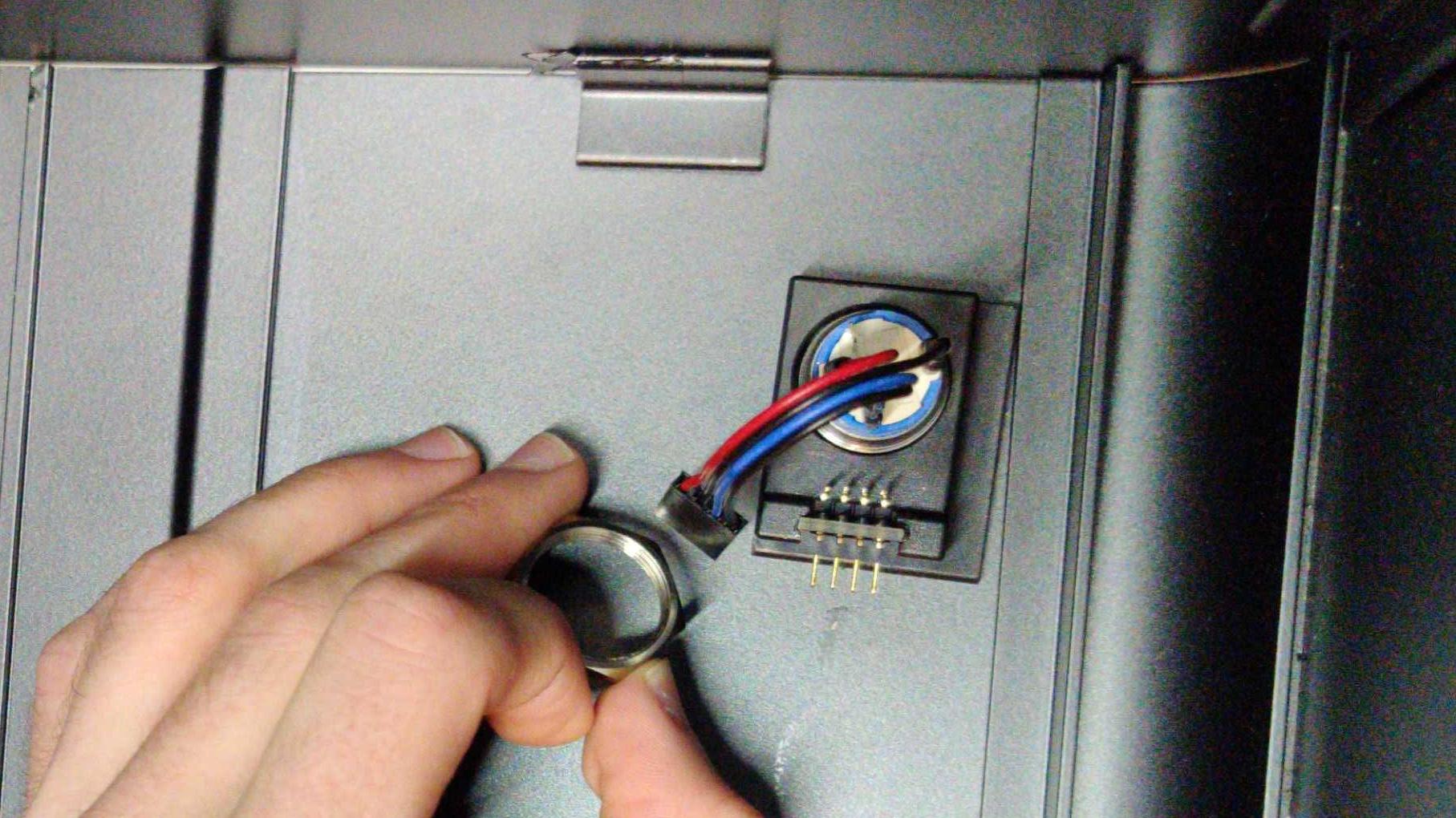
Fig. 24: Inserting cables through nut.
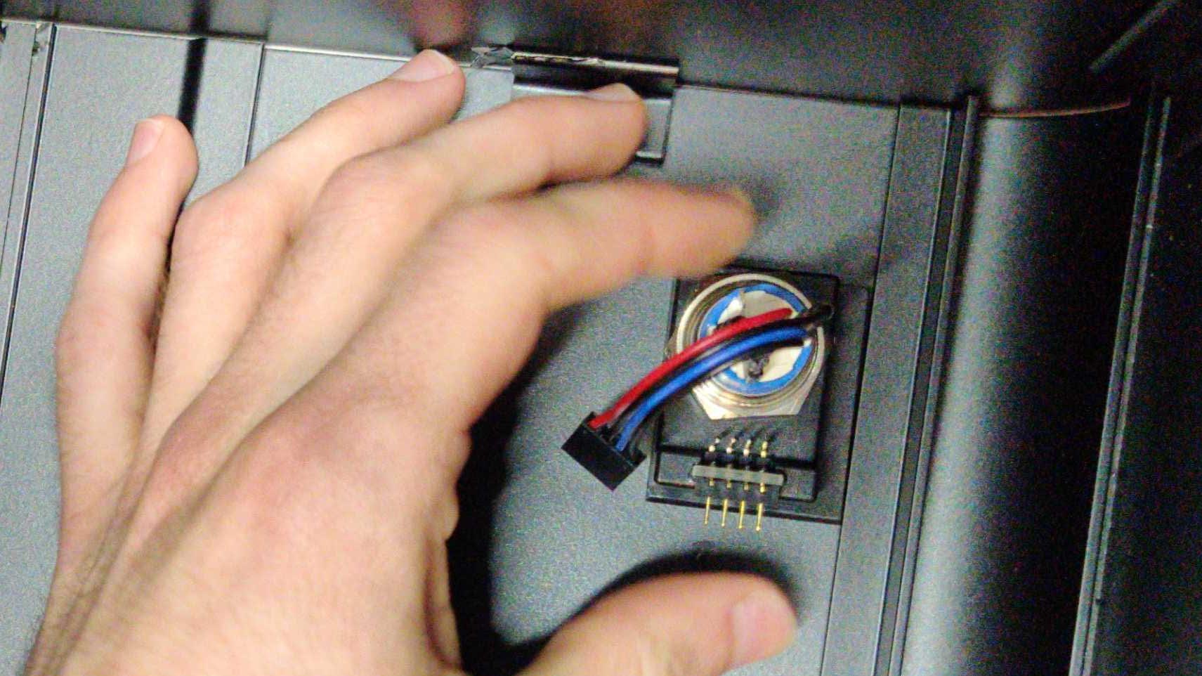
Fig. 25: Finger tightening the nut.
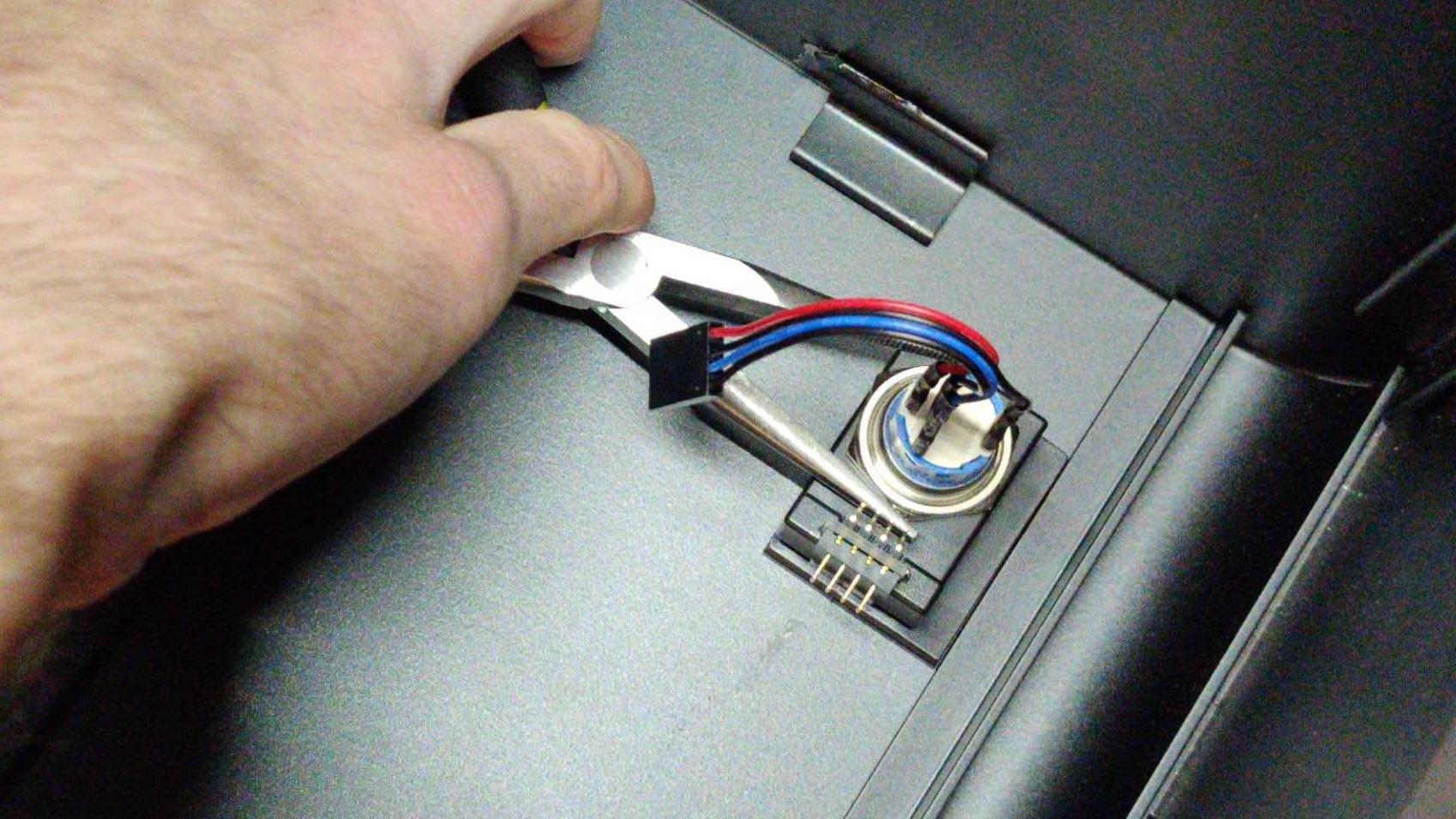
Fig. 26: Tightening the nut with needle-nose pliers
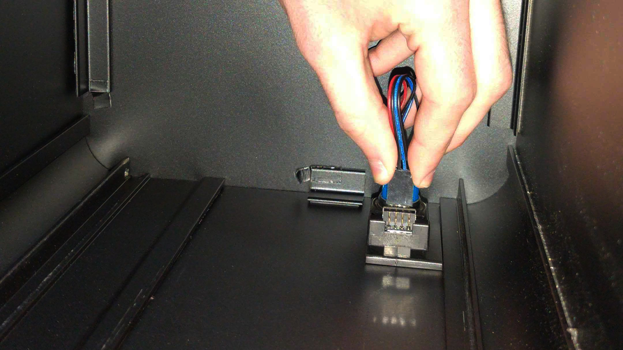
Fig. 27: Connecting the 90-degree connector.
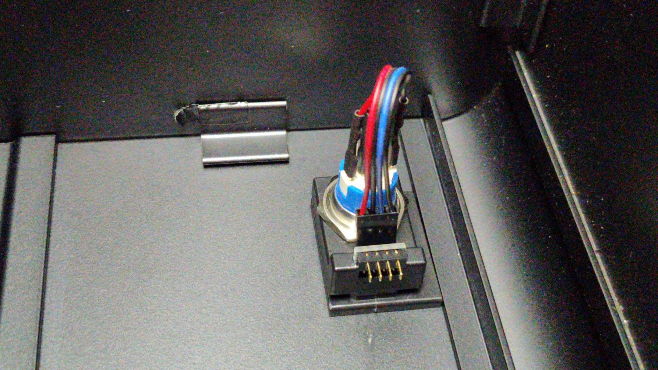
Fig. 28: The completed power button assembly.
CPU Cooler Duct (Remove or replace)
Removing the CPU Cooler Duct
Tools required: Cross-head (Phillips) screwdriver
Time estimate: 2 minutes
Difficulty: Easy
Screws: 16 total
- 8 Thumbscrews (Phillips/Cross-head) Top Case.
- 4 Thumbscrews (Phillips/Cross-head) Duct.
- 4 Non-Thumbscrews (Phillips/Cross-head) Duct Bracket.
- Follow the steps in Removing the Top Case
- Next, unfasten the duct. To do this, unscrew the 4 thumbscrews near the top of your chassis. They frame the planet themed air-vent (see fig 18 above).
- Unscrew the four (4) support bracket screws holding up the cooler duct. There are two (2) Cross-head (Phillips) screws at the bottom of the chassis, and two (2) on the side of the duct.
- Set the bracket and screws safely aside.
- Slide the Cooler Duct horizontally off of the CPU Cooling fan, and set it aside.
- You are now free to perform work on the CPU Cooler fan, or access other components that may have been obstructed by the duct.
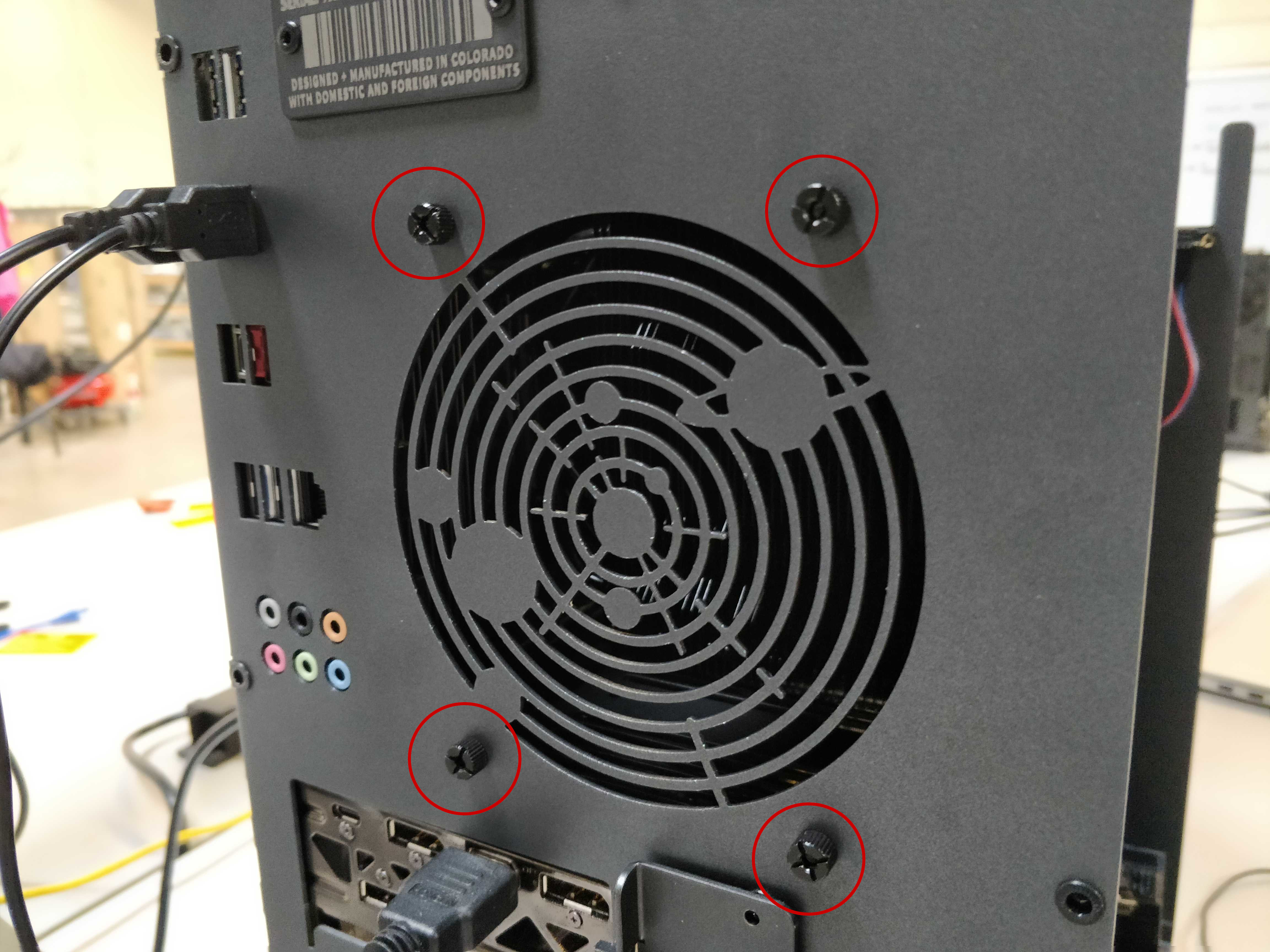
Fig. 29: the 4 CPU Cooler Duct thumbscrews.
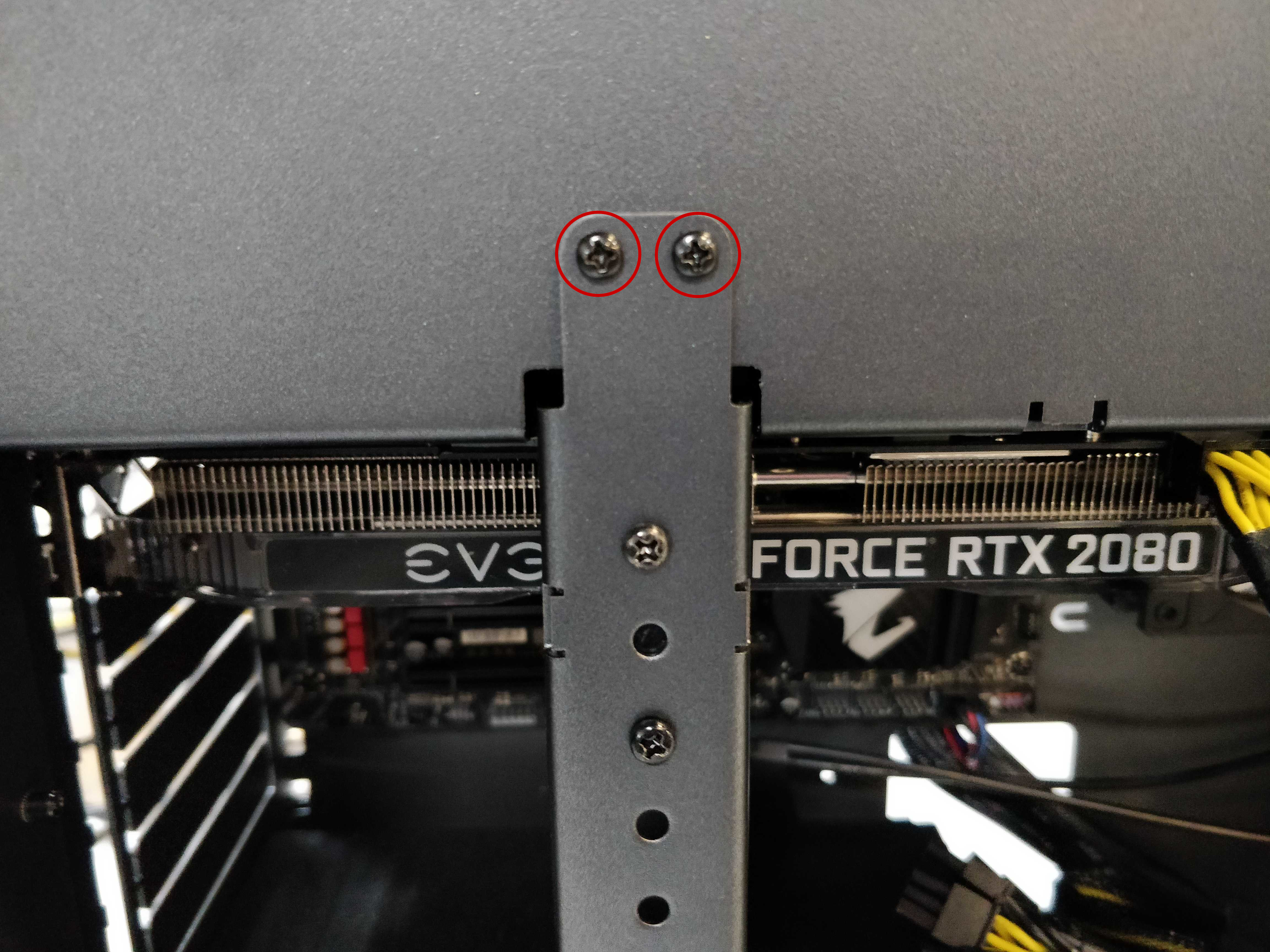
Fig. 30: Top two Phillips screws of the Cooler bracket.
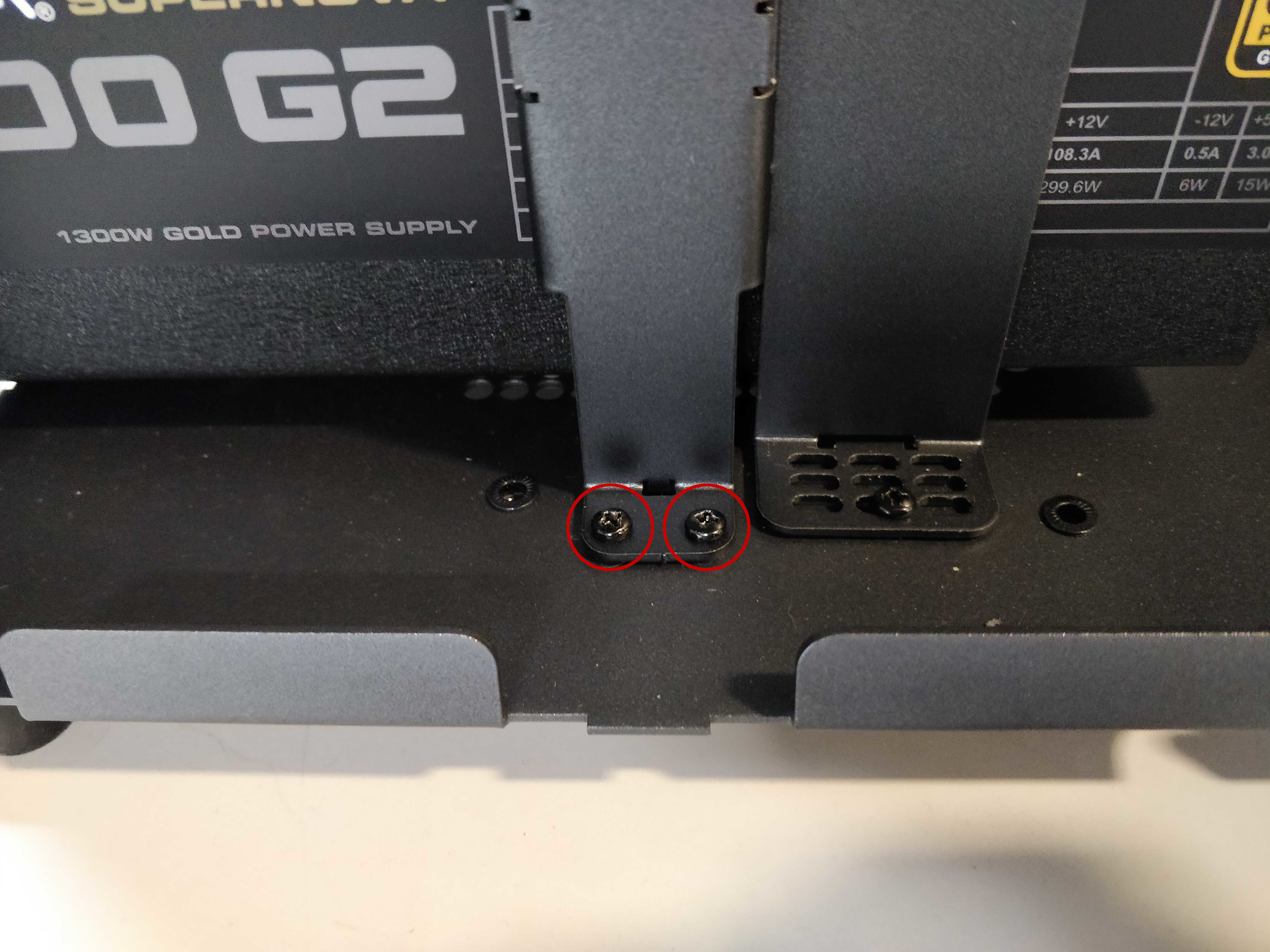
Fig. 31: Bottom two Phillips screws of the Cooler bracket.
Fig. 32: Showing the direction to remove the Cooler Duct.
Fig. 33: Exposed Cooler Duct.
Fig. 34: Removed Cooler Duct for reference.
Fig. 35: Removed CPU Cooler Duct and attached fan beside Thelio Chassis.
Replacing the CPU Cooler Duct
Tools required: Fingers or Cross-head (Phillips) screwdriver
Time estimate: 2 minutes
Difficulty: Easy
Screws: 16 total
- 8 Thumbscrews (Phillips/Cross-head) Top Case.
- 4 Thumbscrews (Phillips/Cross-head) Duct.
- 4 Non-Thumbscrews (Phillips/Cross-head) Duct Bracket.
- Slide the Cooler Duct horizontally over the CPU cooling fan, encasing it.
- Align the holes of the duct with the holes framing the air-vent on the back of the chassis.
- Replace the four thumbscrews on the back of the case, fastening the duct to the outer frame.
- Replace the four (4) support bracket screws holding up the cooler duct. There are two (2) Cross-head (Phillips) screws at the bottom of the chassis, and two (2) on the side of the duct.
- Follow the steps in Replacing the Top Case.
Fig. 36: The exposed cooler.
Fig. 37: Direction for replacing the duct.

Fig. 38: Top two Phillips screws of the Cooler bracket replaced.

Fig. 39: Bottom two Phillips screws of the Cooler bracket.

Fig. 40: Replacing the CPU Cooler Duct thumbscrews.
RAM (Remove or Replace)
The motherboard in the Thelio Majors require specific placement of the RAM sticks in order for the RAM modules to be utilized properly and for the system to boot.
You can use the following tables to determine the placement of your RAM modules by number used.
Thelio Major B1
| Modules Used | DDR4_1_1B | DDR4_3_2B | DDR4_2_1A | DDR4_4_2A | CPU | DDR4_4_2C | DDR4_2_1C | DDR4_3_2D | DDR4_1_1D |
|---|---|---|---|---|---|---|---|---|---|
| 2 Modules | X | X | X | X | X | X |
| Modules Used | DDR4_1_1B | DDR4_3_2B | DDR4_2_1A | DDR4_4_2A | CPU | DDR4_4_2C | DDR4_2_1C | DDR4_3_2D | DDR4_1_1D |
|---|---|---|---|---|---|---|---|---|---|
| 4 Modules | X | X | X | X |
| Modules Used | DDR4_1_1B | DDR4_3_2B | DDR4_2_1A | DDR4_4_2A | CPU | DDR4_4_2C | DDR4_2_1C | DDR4_3_2D | DDR4_1_1D |
|---|---|---|---|---|---|---|---|---|---|
| 6 Modules | X | X |
| Modules Used | DDR4_1_1B | DDR4_3_2B | DDR4_2_1A | DDR4_4_2A | CPU | DDR4_4_2C | DDR4_2_1C | DDR4_3_2D | DDR4_1_1D |
|---|---|---|---|---|---|---|---|---|---|
| 8 Modules |
Thelio Major B2
| Modules Used | DDR4_1_1B | DDR4_3_2B | DDR4_2_1A | DDR4_4_2A | CPU | DDR4_4_2C | DDR4_2_1C | DDR4_3_2D | DDR4_1_1D |
|---|---|---|---|---|---|---|---|---|---|
| 2 Modules | X | X | X | X | X | X |
| Modules Used | DDR4_1_1B | DDR4_3_2B | DDR4_2_1A | DDR4_4_2A | CPU | DDR4_4_2C | DDR4_2_1C | DDR4_3_2D | DDR4_1_1D |
|---|---|---|---|---|---|---|---|---|---|
| 4 Modules | X | X | X | X |
| Modules Used | DDR4_1_1B | DDR4_3_2B | DDR4_2_1A | DDR4_4_2A | CPU | DDR4_4_2C | DDR4_2_1C | DDR4_3_2D | DDR4_1_1D |
|---|---|---|---|---|---|---|---|---|---|
| 6 Modules | X | X |
| Modules Used | DDR4_1_1B | DDR4_3_2B | DDR4_2_1A | DDR4_4_2A | CPU | DDR4_4_2C | DDR4_2_1C | DDR4_3_2D | DDR4_1_1D |
|---|---|---|---|---|---|---|---|---|---|
| 8 Modules |
Thelio Major R1/R2
| Modules Used | DDR4_D2 | DDR4_D1 | DDR4_C2 | DDR4_C1 | CPU | DDR4_A1 | DDR4_A2 | DDR4_B1 | DDR4_B2 |
|---|---|---|---|---|---|---|---|---|---|
| 1 Modules | X | X | X | X | X | X | X |
| Modules Used | DDR4_D2 | DDR4_D1 | DDR4_C2 | DDR4_C1 | CPU | DDR4_A1 | DDR4_A2 | DDR4_B1 | DDR4_B2 |
|---|---|---|---|---|---|---|---|---|---|
| 2 Modules | X | X | X | X | X | X |
| Modules Used | DDR4_D2 | DDR4_D1 | DDR4_C2 | DDR4_C1 | CPU | DDR4_A1 | DDR4_A2 | DDR4_B1 | DDR4_B2 |
|---|---|---|---|---|---|---|---|---|---|
| 4 Modules | X | X | X | X |
| Modules Used | DDR4_D2 | DDR4_D1 | DDR4_C2 | DDR4_C1 | CPU | DDR4_A1 | DDR4_A2 | DDR4_B1 | DDR4_B2 |
|---|---|---|---|---|---|---|---|---|---|
| 6 Modules | X | X |
| Modules Used | DDR4_D2 | DDR4_D1 | DDR4_C2 | DDR4_C1 | CPU | DDR4_A1 | DDR4_A2 | DDR4_B1 | DDR4_B2 |
|---|---|---|---|---|---|---|---|---|---|
| 8 Modules |
Removing RAM Sticks
You can find video instructions on this process here.
Link for the video for RAM Service: (https://youtu.be/OFv8ByuDGU0)
Tools required: Fingers or Crosshead (Phillips) screwdriver (for Top Case)
Time estimate: 5 minutes
Difficulty: Easy
Screws: 12 total
- 12 Thumbscrews (Phillips/Crosshead).
- Follow the steps in Removing the Top Case.
- It may be helpful, but is not necessary, to Remove the CPU Cooler Duct.
- Press simultaneously on each clip on either side of the RAM stick (fig 21 above). These clips will release the RAM stick and lever it out of it’s slot on the board.
- Gently, but firmly pull the RAM straight out of the slot, and set aside.

Fig.41: Accessing the RAM release clips.

Fig. 42: Placement of the RAM notch on the motherboard.
Fig. 43: Placement of the RAM notch on the RAM stick.
Replacing RAM Sticks
Tools required: Fingers or Crosshead (Phillips) screwdriver (for Top Case)
Time estimate: 5 minutes
Difficulty: Easy
Screws: 12 total
- 12 Thumbscrews (Phillips/Crosshead).
- Line up the notch on the stick with the notch in the slot. One side of the RAM stick has fewer pins and is shorter. This will help you orient the stick.
- Insert the RAM stick in the slot. The order of the slots matters, (see tables above).
- Press evenly on the memory stick until both tabs lock into place. You’ll hear two clicks once it’s seated, and the clips will snap closed against the RAM.
- Once the RAM is in place, replace the CPU Cooler Duct (if applicable).
- Replace the Top Case.
- Reconnect external devices: keyboard, mouse, monitor(s).
- Reconnect external power cable and turn power-supply switch to the on position.
- Power the Thelio on to ensure the RAM is working correctly. If so, the computer will boot normally.

Fig. 44: Indicating the RAM notch on the motherboard.

Fig. 45 Indicating the RAM notch on the RAM stick.

Fig. 46 Pressing the RAM stick down into place.
GPU (Remove or replace)
Removing the GPU
In this guide, you will learn how to remove the graphics card on your Thelio. These steps must be taken in order to replace the GPU. You can find video instructions on this process here.
Link for the video for GPU removal: (https://youtu.be/3bUcp0S1HrE)
For this procedure, a Cross-head (Phillips) screwdriver may be helpful, as well as a wooden or plastic (non-conductive) tool for reaching between components. A pencil, ruler, chopsticks or a plastic computer repair tool will work well. Do not use anything made of metal.
Tools required: Fingers or Cross-head (Phillips) screwdriver, a tool for pressing the GPU release bracket (non-conductive).
Time estimate: 10 minutes.
Difficulty: Medium
Screws: 19 total
- 19 Thumbscrews (Phillips/Cross-head).
Before you remove the lid, be sure to power off and unplug all cords from the computer.
- First follow the steps in Removing the Top Case.
- It may also be helpful to Remove the CPU Cooler Duct.
- To remove your graphics card, twist off the 3 thumbscrews from the PCI bracket.
- Remove the GPU brace. Unscrew the bottom two screws, and then the top two screws, to remove the brace. Both the PCI bracket and the GPU brace keep your graphics card secure and in place (Fig 23).
- Remove the GPU from the PCIe slot by pressing on the release clip on the right. This is where your chosen (non-metal) poking tool may come in handy, to reach the clip on the board without trying to squeeze your hand between components.
- Disconnect the power cables from the GPU (if applicable), and tie back any cables you are not planning on using with the provided velcro straps.
- Now you are ready to install an alternative or replacement GPU.
- If you are not planning on installing another GPU follow the steps to Replace the CPU Cooler Duct, Replace the Top Case, and reconnect all cables and peripherals.
Fig. 47: Close view of the GPU leaving the PCIe slot (top) and the PCIe release switch (bottom).
Replacing the GPU
For this procedure, a Cross-head (Phillips) screwdriver may be helpful, as well as a wooden or plastic (non-conductive) tool for reaching between components. A pencil, ruler, chopsticks or a plastic computer repair tool will work well. Do not use anything made of metal.
Tools required: Fingers or Crosshead (Phillips) screwdriver, a tool for pressing the GPU release bracket (non-conductive).
Time estimate: 10 minutes.
Difficulty: Medium
Screws: 19 total
- 19 Thumbscrews (Phillips/Crosshead).
If you have not yet completed the steps to remove the PCI bracket and GPU brace, you will find these instructions in the section on Removing the GPU
NOTE: Some GPU's use the PCI-e slot for power and don't need a cable. If your Thelio is configured with a Radeon RX 550 graphics card, for example, you will not find any power connector slots on your GPU. The cards compatible with this Thelio model require 8-pin, 12 pin or 16-pin power cable connections.

Fig: 48 Showing variations of pin connections on GPU cards - 16-pin (left), 12-pin (middle), 8-pin (right).
Fig. 49: Thelio internal context view of PCIe slot.
Fig. 50: Close up view of the PCIe slots.
- After removing the GPU (Or, if no GPU is installed, removing the bracket, insert the new graphics card into the PCIe slot until it clicks into place.
- Once the GPU is securely in place, attach the internal and external brackets.
- Securely fasten the brackets in place with the provided thumbscrews.
- Prepare the necessary power connectors for your graphics card. You can tell which wires you’ll need by looking at the ports on the front of your GPU. The necessary cabling is provided inside your Thelio’s chassis.
- Do not connect the cables to the GPU until it has been inserted in the PCIe slot and secured with the brackets.
- Connect the power cables to the GPU selecting the cables based on the number of pins (See NOTE below).
- Wrap up any unused wires with the velcro strap and store those wires back in the chassis so that they’re not blocking the fan.
- Once the GPU is connected and the power cables secured (fig #), replace the Top Case, reconnect external power cable.
- Turn the power supply switch at the rear of the machine to the “on” position.
Drives (Remove or Replace)
In this guide, you will learn how to remove or replace drives in your Thelio. You can find video instructions on this process here.
Link for the video for Drive Service removal: (https://youtu.be/6fIeVEaY7dE)
2.5" SATA Drives
The Thelio Major B2 provides eight (8) slots for 2.5” SATA drives. They are housed in the Thelio Drive Cage for easy access. Each drive is connected to a SATA port on the Thelio IO board, which acts as a conduit, connecting the drives to the motherboard.
M.2 Drives
The number and location of M.2 drives, differs between the Thelio Major R and B models.
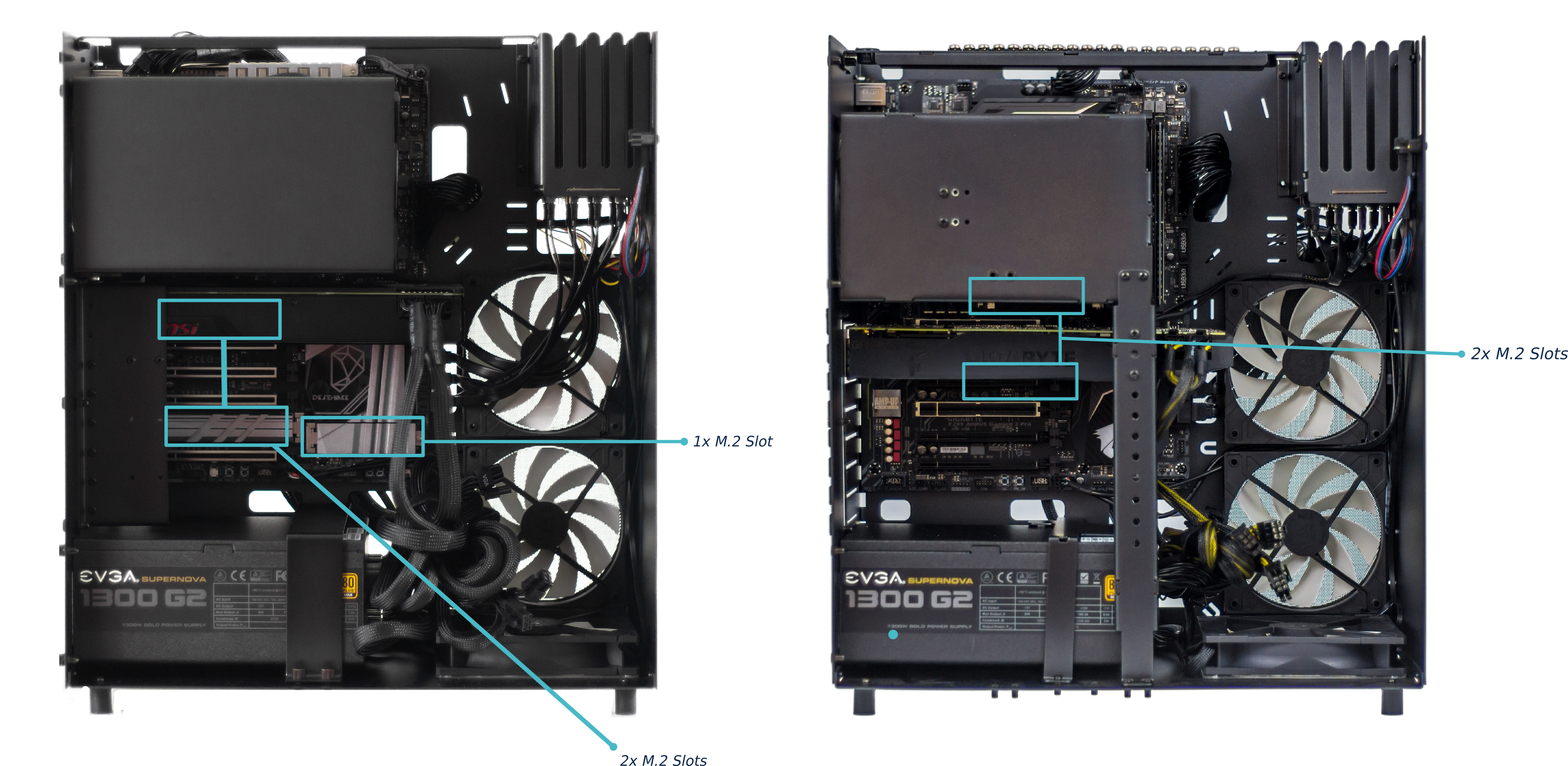 Fig. 52: Thelio Major (thelio-major-r2) front M.2 drive slots (left).
Fig. 53: Thelio Major (thelio-major-b2) front M.2 drive slots (right)
Thelio Major R2
The Thelio Major R2 has three (3) M.2 drive slots. One on the board, above the PCIe slot which holds the GPU, one below the right-side RAM slots, and one to the right of the lower 3 PCIe slots (Fig. 52).
Thelio Major B2
The Thelio Major B2 has one two (2) M.2 Drive slots. One on above the top PCIe slot, and one below the top PCIe slot (Fig. 53).
Depending on the M.2 drive slot you intend to use, remove the CPU Cooler Duct and/or GPU to gain easier access. You can find video instructions on this process here.
Link for the video for GPU removal: (https://youtu.be/3bUcp0S1HrE)
Replacing a 2.5 Drive
Tools required: Fingers or Crosshead (Phillips) screwdriver, a tool for pressing the GPU release bracket (non-conductive).
Time estimate: 10 minutes.
Difficulty: Easy
Screws: 12 total
- 8 Thumbscrews (Phillips/Crosshead) in the Top Case.
- 4 Thumbscrews (Phillips/Crosshead) per Drive.
Before you remove the lid, be sure to power off and unplug all cords from the computer.
To remove the drive, gently pull on the drive and slide it out from the drive cage.
Installing a 2.5 Drive
Tools required: Fingers or Crosshead (Phillips) screwdriver, a tool for pressing the GPU release bracket (non-conductive).
Time estimate: 10 minutes.
Difficulty: Easy
Screws: 12 total
- 8 Thumbscrews (Phillips/Crosshead) in the Top Case.
- 4 Thumbscrews (Phillips/Crosshead) per Drive.
To add a 2.5-inch drive, you’ll need 4 screws to secure the drive in place. Extra screws are provided on the chassis for convenience.
- Follow the steps to Remove the Top Case.
- You may want to remove the washer out of the provided bar-bracket. Do so by pushing up from underneath the bracket until the washer pops out.
- Next, slide each screw along the bar-bracket to the opening and remove the screw.
- Screw these four thumbscrews into the holes at the corners of the drive to keep it securely fastened in the drive cage.
- Before inserting the drive into the drive cage, line up the connectors on the drive with the connectors in the drive cage.
- Then, line up the inside of the grommet with the prongs on the drive cage, and insert the drive until it locks into place.
- Replace the Top Case and reconnect all cables.
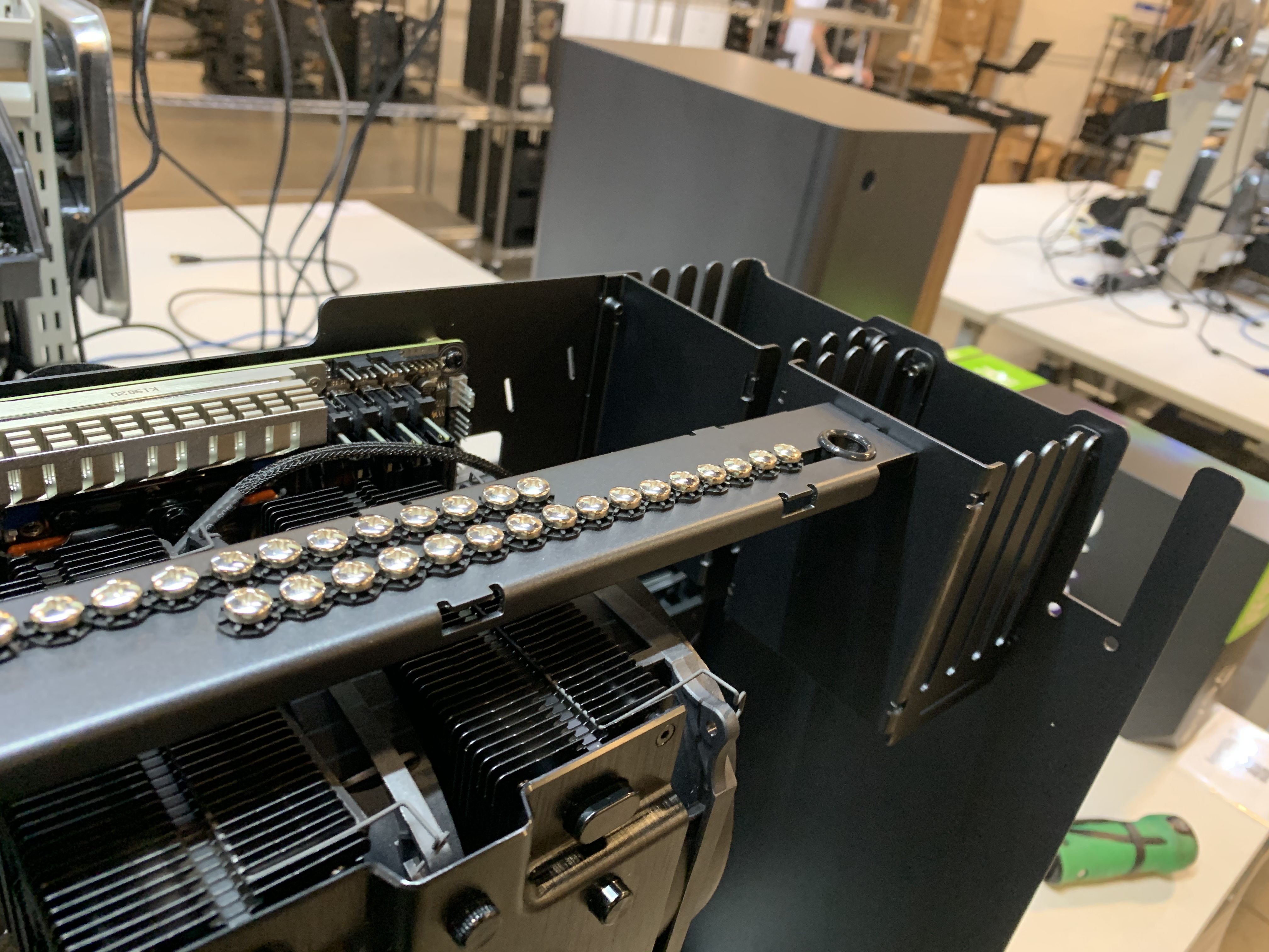
Fig.54: Thelio Top Bracket with provided drive screws.
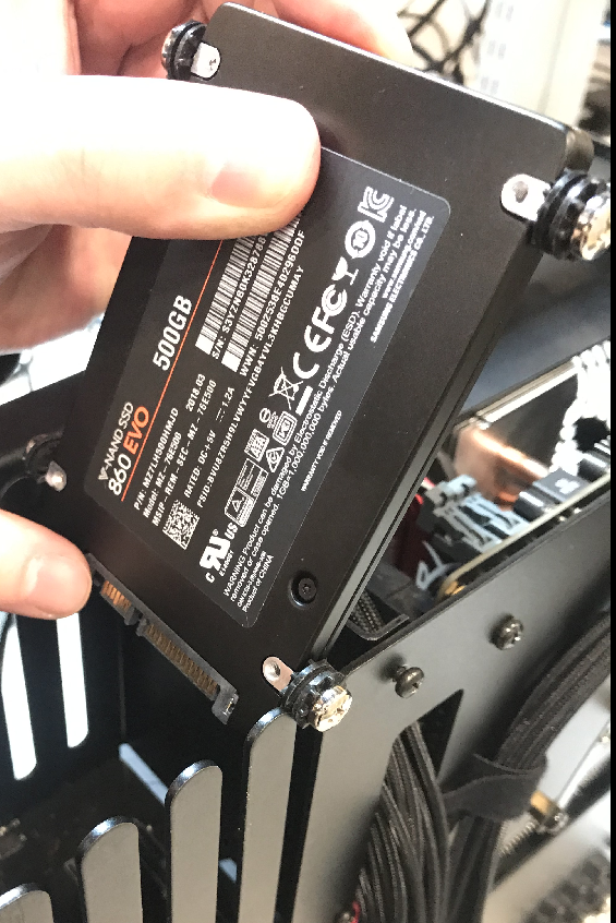
Fig. 55: Aligning the drive screws and grommets with drive cage slots.
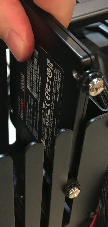
Fig. 56: Inserting the drive in to the cage slot.
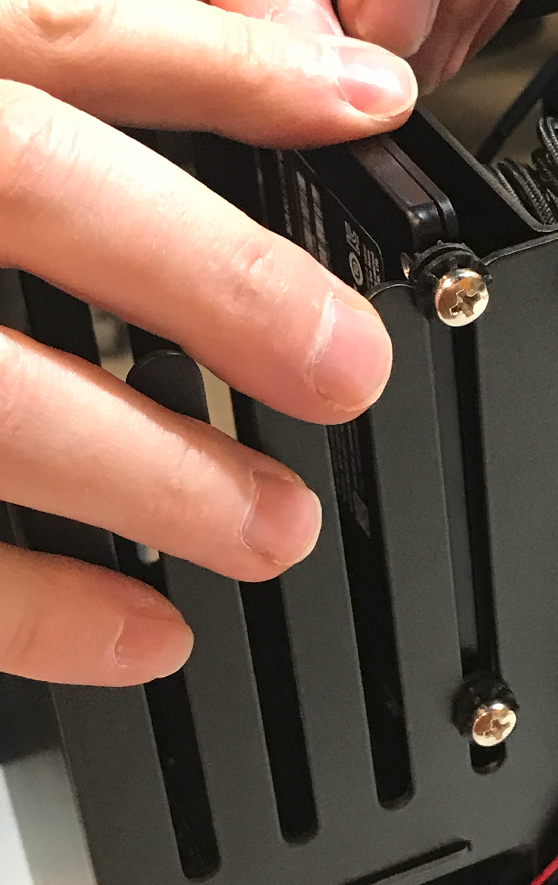
Fig. 57: Drive inserted almost fully in the slot.
Fig: 58 Pressing the drive firmly into place.
Removing an M.2 Drive
Removing an M.2 may require removal of the GPU or CPU Cooler Duct for easier access. A Crosshead (Phillips) screwdriver is required.
Tools required: Fingers or Crosshead (Phillips) screwdriver, a tool for pressing the GPU release bracket (non-conductive).
Time estimate: 5-10 minutes.
Difficulty: Easy
Screws: 9 total
- 8 Thumbscrews (Phillips/Crosshead) in the Top Case.
- 1 M.2 securing screw (per Drive).
- Follow the steps to Remove the Top Case.
- Remove the CPU Cooler Duct (if applicable).
- Remove the GPU (if applicable).
- Unscrew the M.2 screw opposite the M.2 slot. Set it safely aside.
- Gently, but firmly remove the M.2 drive horizontally from the slot.
- Replace the screw, fastening the M.2 in place.
- Replace the GPU (if applicable).
- Replace the CPU Cooler Duct (if applicable).
- Replace the Top Case.
- Reconnect all cables and peripherals.
Replacing an M.2 Drive
Replacing an M.2 drive may require removal of the GPU or CPU Cooler Duct for easier access. A Crosshead (Phillips) screwdriver is required.
Tools required: Fingers or Crosshead (Phillips) screwdriver, a tool for pressing the GPU release bracket (non-conductive).
Time estimate: 5-10 minutes.
Difficulty: Easy
Screws: 13 total
- 12 Thumbscrews (Phillips/Crosshead) in the Top Case.
- 1 M.2 securing screw (per Drive).
- Follow the steps to Remove the Top Case.
- Remove the CPU Cooler Duct (if applicable).
- Remove the GPU (if applicable).
- Unscrew the M.2 screw opposite the M.2 slot. Set it safely aside.
- Line up the notch on the M.2 drive.
- Insert the new drive into its port on the motherboard.
- Replace the screw, fastening the M.2 in place.
- Replace the GPU (if applicable).
- Replace the CPU Cooler Duct (if applicable).
- Replace the Top Case.
- Reconnect all cables and peripherals.
NOTE: By default, the first of the two M.2 drives (NVMe or not) stores your operating system, so you will need to reinstall the OS after replacing it. This can be done by restoring from a backup, or from a fresh install.
Pop!_OS users, instructions to reinstall the OS can be found here: https://support.system76.com/articles/install-pop/
Ubuntu users, instructions to reinstall the OS can be found here: https://support.system76.com/articles/install-ubuntu/.
CPU Thermal Paste (Remove or Replace)
If you are experiencing thermal issues with your Thelio, one possible solution is to change the Thermal paste. Thermal paste helps transfer heat from the CPU to the CPU Cooler via the heat sink.
Thermal paste can lose its effectiveness over time and may need to be re-applied.
This guide will explain how to remove the CPU Cooler, clean the CPU of thermal paste, and reapply a new coat.
WARNING: DO NOT use your Thelio without thermal paste. Running the machine without thermal paste could result in overheating, system shutdowns and possibly damage to the internal components.
Remove the CPU Thermal Paste
Removing CPU thermal paste requires removal of the CPU Cooler Duct. It may also require removing the GPU for easier access.
Tools required: Crosshead (Phillips) screwdriver, Rubbing Alcohol, Paper Towels, Thermal Paste.
Time estimate: 15-20 mins.
Difficulty: Hard
Screws: 16 total
- 8 Thumbscrews (Phillips/Crosshead) on the Top Case.
- 4 Thumbscrews (Phillips/Crosshead) on the CPU Cooler Duct.
- 4 Bracket Screws securing the CPU heat sink.
- Follow the steps in Removing the Top Case.
- Follow the steps in Removing the CPU Cooler Duct.
- Follow the steps in Removing the GPU (if applicable).
- Gently but firmly separate the Cooling Fans from the Heat Sink. The fans are held on by clips which can be pried from the sides of the heat sink.
- Next, disconnect the power cables from the Cooling Fans.
- Remove the four (4) bracket screws fastening the Heat Sink to the board. Loosen the screws one at a time. Move from opposite corner to opposite corner, diagonally across the Heat Sink. For example: first, top left screw, then bottom right screw (fig. 34). This ensures even pressure between the brackets and the motherboard.
- Lift the Heat Sink off of the motherboard.
- You’ll notice that there is Thermal Paste coating the bottom of the Heat Sink as well as the CPU core.
- Apply Rubbing Alcohol to a sheet of Paper Towel and wipe the Thermal Paste off of the bottom of the Heat Sink and CPU core until they are totally clean.
- If you are replacing the Thermal Paste, continue on to the section Replacing the CPU Thermal Paste (See Important NOTE below).
- Replace the Heat Sink over the CPU core.
- Re-fasten the Heat Sink screws, again using the opposite corner method described above.
- Follow the steps to Replace the GPU (if applicable).
- Follow the steps to Replace the CPU Cooler Duct.
- Follow the steps to Replace the Top Case.
Replace the CPU Thermal paste
Replacing CPU thermal requires removal of the CPU Cooler Duct. It may also require removing the GPU for easier access.
Tools required: Crosshead (Phillips) screwdriver, Thermal Paste.
Time estimate: 15-20 mins.
Difficulty: Easy
Screws: 12 total
- 8 Thumbscrews (Phillips/Crosshead) on the Top Case.
- 4 Thumbscrews (Phillips/Crosshead) on the CPU Cooler Duct.
- 4 Bracket Screws securing the CPU heat sink.
- Follow steps 1-9 in Removing the CPU Thermal Paste.
- Once the Heat Sink and CPU core are free of old Thermal Paste, apply new paste in a line down the middle of the CPU core (fig. 37).
- Once the paste is applied, replace the Heat Sink over top of it. The Heat Sink will spread the thermal paste across the CPU core, there is no need to spread it yourself.
- Re-fasten the four (4) screws on the Heat Sink. In fastening the screws, partially tighten them one at a time, and move diagonally to the opposite corner. For example, tighten the top-left screw halfway, then move to the bottom right, and tighten that halfway. Repeat until all screws are tight. This ensures even pressure between the brackets and the motherboard.
- Once the Heat Sink is fastened down, clip the CPU Cooling Fans back onto the Heat Sink.
- Reconnect the power cables to the CPU Cooling Fans.
- Follow the steps in Replacing the GPU (if applicable).
- Next, follow the steps in Replacing the CPU Cooler Duct.
- Follow the steps in Replacing the Top Case.
- Reconnect all external cables and peripherals, and turn the Power Supply switch to the “on” position.
- Power on the Thelio to ensure successful boot.
NOTE: The pictures shown here are the Thelio R1 (AMD) model with a Threadripper processor. However, the process and cautions when removing and replacing thermal paste are the same for both Intel and AMD Thelio Majors.
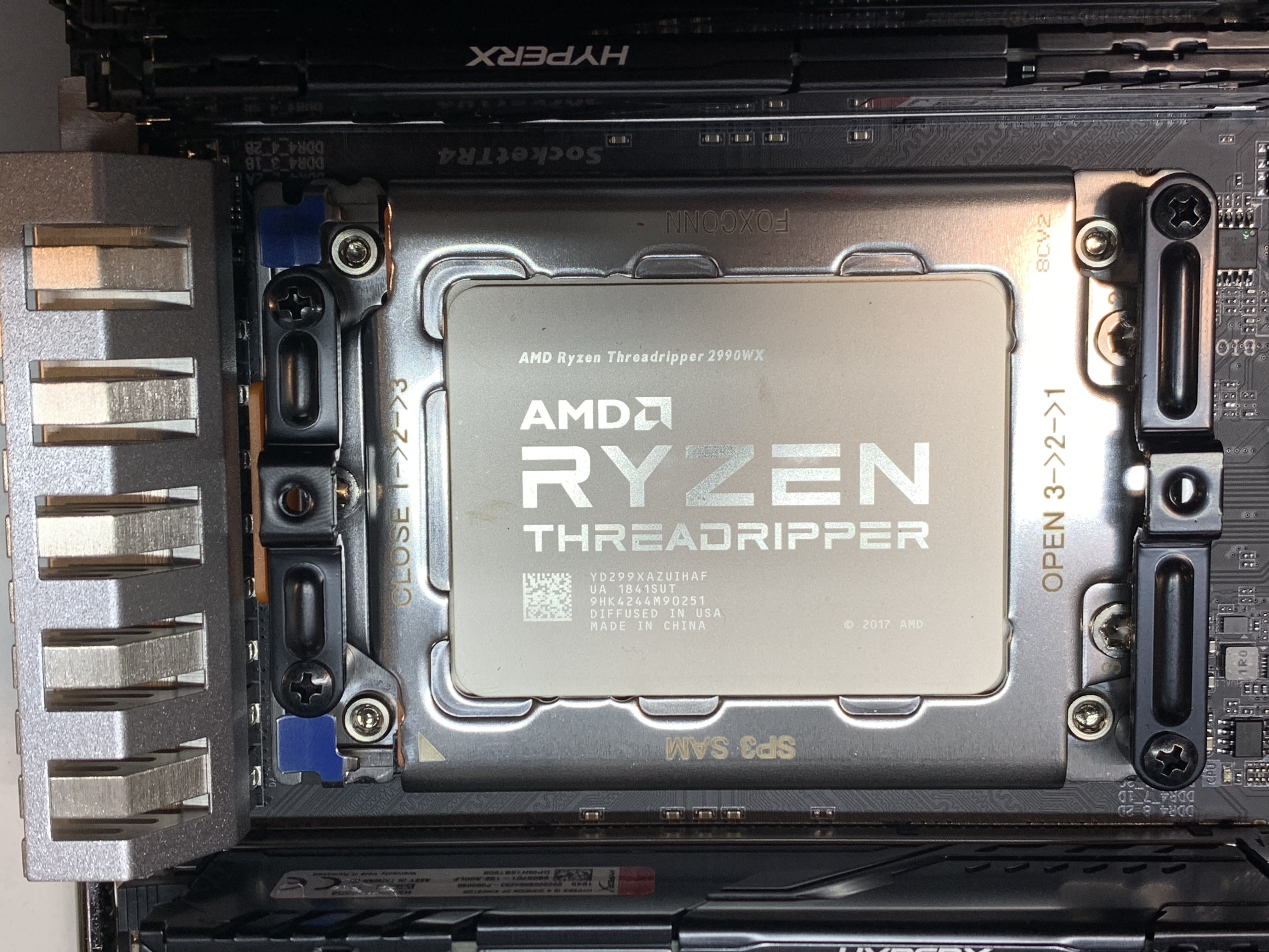
Fig. 59: A cleaned CPU core.

Fig. 60: Reapplied thermal paste on the core.
Thelio Mega (thelio-mega-r1.0)
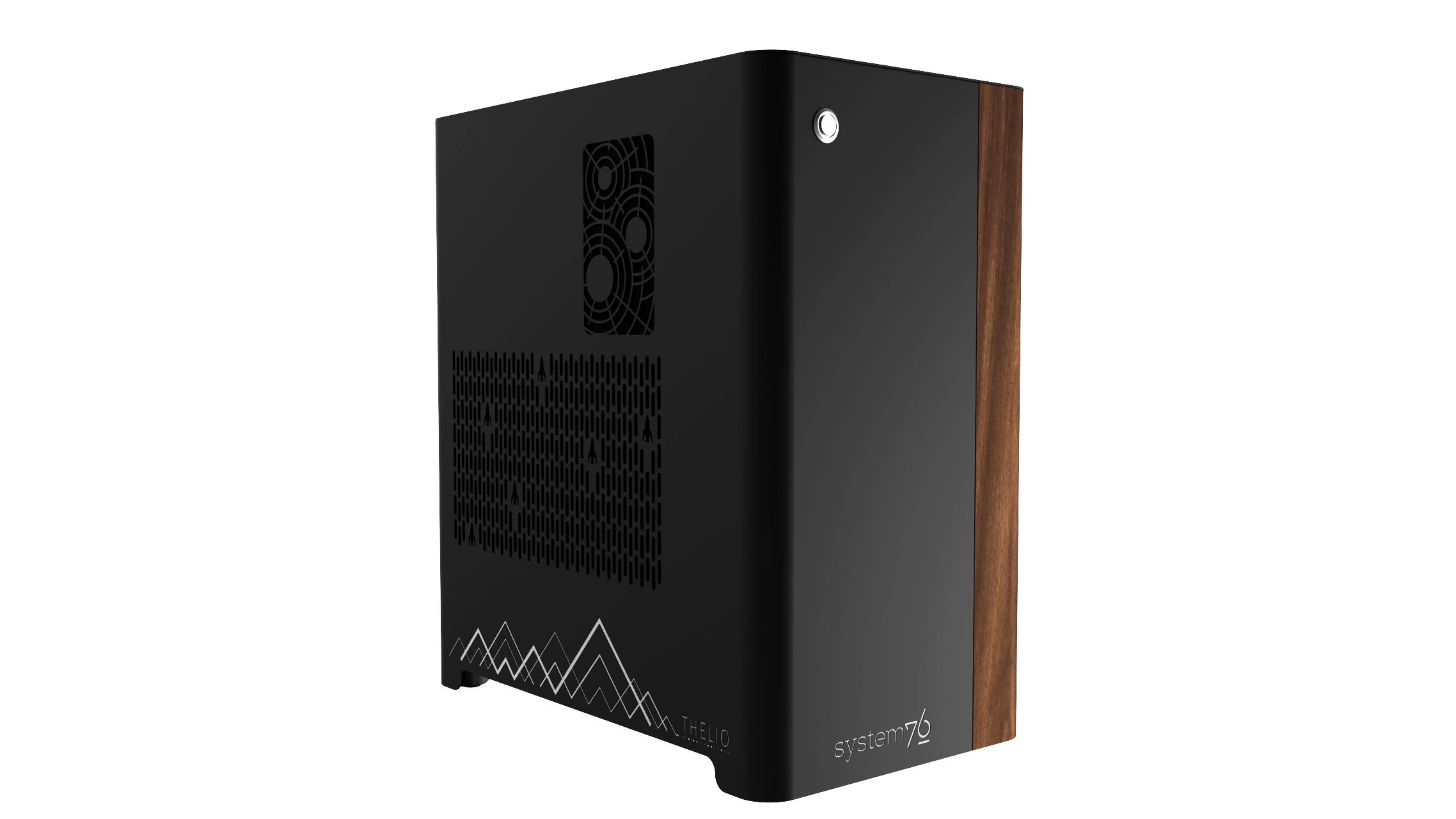
The System76 Thelio Mega is a desktop with the following specifications:
- CPU options
- Motherboard
- Gigabyte TRX40 Aorus Xtreme (rev. 1.0 or 1.1) running System76 Firmware (non-open)
- AMD TRX40 chipset
- Daughterboard
- Thelio Io board running open-source firmware
- GPU options
- Up to four GPUs, depending on configuration (2x PCIe 4.0 x16 and 2x PCIe 4.0 x8)
- GPU size:
- Internal clearance: 425.80mm
- Recommended maximum length:415.80mm
- Tested with the following GPUs:
- NVIDIA Quadro RTX 4000 (maximum 4)
- 3x DisplayPort 1.4, DisplayPort over USB-C (VirtualLink)
- NVIDIA GeForce 2080 Ti (maximum 4)
- HDMI 2.0b, 3x DisplayPort 1.4, DisplayPort over USB-C (VirtualLink)
- NVIDIA GeForce RTX 3090 (maximum 3)
- HDMI 2.1, 3x DisplayPort 1.4a
- NVIDIA Quadro RTX 5000 (maximum 4)
- 4x DisplayPort 1.4, DisplayPort over USB-C (VirtualLink)
- NVIDIA Quadro RTX 6000 (maximum 4)
- 4x DisplayPort 1.4, DisplayPort over USB-C (VirtualLink)
- NVIDIA Quadro RTX 8000 (maximum 4)
- 4x DisplayPort 1.4, DisplayPort over USB-C (VirtualLink)
- NVIDIA Quadro RTX 4000 (maximum 4)
- Memory
- Up to 256GB (8x32GB) quad-channel ECC Unbuffered DDR4 DIMMs @ 3200 MHz
- Tested with the following RAM modules (may ship with other tested modules):
- Networking
- 2x 10-Gigabit Ethernet (Intel 10GbE LAN chip)
- Combined total is 10Gbit/s; ports will run at 5Gbit/s if used at the same time.
- Wi-Fi 6 (Intel AX200)
- 2x 10-Gigabit Ethernet (Intel 10GbE LAN chip)
- Power
- EVGA SuperNOVA 1600W T2 80+ Titanium Certified PSU
- C19 power cord
- Sound
- 3.5mm line out, line in, microphone jacks
- Optical S/PDIF out
- Up to 7.1-channel audio output
- Realtek ALC4050H + ALC1220-VB audio chipset
- HDMI, DisplayPort, USB-C DisplayPort audio (depending on GPU)
- Storage
- 4x M.2 (PCIe Gen 4)
- Backwards compatible with M.2 SATA and PCIe Gen 3.
- 8x 2.5" SATA
- When using all four M.2 slots, some SATA ports will not function. See Parts & Repairs for details.
- 4x M.2 (PCIe Gen 4)
- USB
- 7x USB 3.2 Gen 2 Type-A
- 1x USB 3.2 Gen 2 Type-C
- Dimensions
- 47.8cm x 26.3cm x 43.8cm
Thelio Mega (External Overview)
Back side overview:

Audio Port Guide:
- Top row, left to right:
- Optical S/PDIF Out (square)
- Rear Speaker Out
- Center/Subwoofer Out
- Bottom row, left to right:
- Mic in
- Line Out / Front Speaker Out
- Line In / Side Speaker Out
Power Switch Guide:
- 1: On
- 0: Off
Note: The Q-Flash+ button (next to the CMOS reset button) is not needed when performing UEFI firmware updates via the System76 Firmware Manager. Use of the Q-Flash+ button is not recommended.
Thelio Mega (Internal Overview)
Side overview:
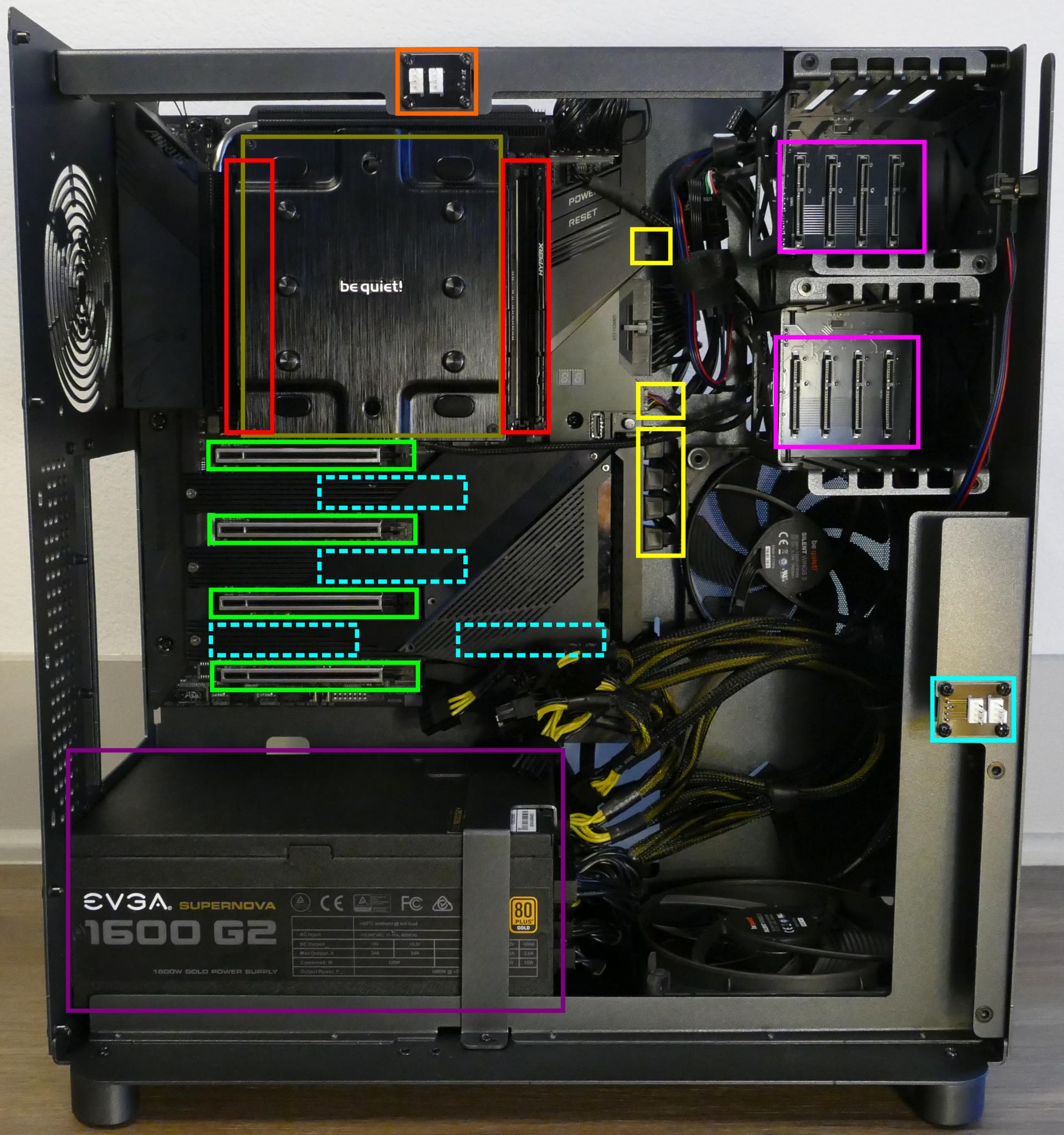
- CPU cooler is highlighted in olive
- RAM slots are highlighted in red
- PCIe slots are highlighted in green
- M.2 slots are highlighted in dashed cyan (located underneath the heatsink)
- 2.5" SATA drive slots are highlighted in pink
- Power supply is highlighted in purple
- Thelio-IO to motherboard connections are highlighted in yellow
- CPU duct fan connectors are highlighted in orange
- Inner partition (GPU) fan connectors are highlighted in solid cyan
PCIe slot guide:
From top to bottom:
- PCIe Gen 4 x16 slot (GPU 1)
- PCIe Gen 4 x8 slot (GPU 4)
- PCIe Gen 4 x16 slot (GPU 2)
- PCIe Gen 4 x8 slot (GPU 3)
See the repairs page for detailed information about installing or replacing components.
Thelio Mega (Parts & Repairs)
Many components in your Thelio Mega can be upgraded or replaced as necessary. Power the machine off, switch off the power supply, and unplug all peripherals before working with any internal components. Then, follow these step-by-step guides for instructions:
- Removing the top case
- Removing the inner partition
- Adding/removing 2.5" storage drives
- Replacing the case fans
- Replacing a GPU
- Replacing the M.2 drives
- Removing the CPU duct
- Replacing the RAM
- Removing the top crossbar
- Replacing the CPU fans
- Replacing the CPU cooler/thermal paste and CPU
- Replacing the power supply
- Replacing the side fans
- Replacing the Thelio-IO boards
- Troubleshooting the power button
- Troubleshooting the Thelio-IO USB connection
Removing the top case:
The top case can be removed to access the internal components.
Tools required: Cross-head (Phillips) screwdriver (optional)
Time estimate: 2 minutes
Difficulty: Easy ●
Steps to remove the top case:
- Remove the eight outer screws holding the top case onto the machine.

- Slide the top case up and off of the machine.
Removing the inner partition:
The inner partition provides a brace for the outer case and helps hold the internal components in place. The partition needs to be removed to access most internal components.
Tools required: Cross-head (Phillips) screwdriver (optional)
Time estimate: 5 minutes
Difficulty: Easy ●
Steps to remove the inner partition:
- Follow the steps above to remove the top case.
- Unscrew the three additional back screws holding the inner partition in place from the back.

- Unplug the two side fan connectors, highlighted cyan below.

- Unscrew the two inner screws holding the partition in place from the side.
- Lift the inner partition away from the case.
Adding/removing 2.5" storage drives:
Thelio Mega r1.0 supports up to eight 2.5" SATA III drives. When using four M.2 drives, the following restrictions apply:
- If the bottom right M.2 slot has a SATA drive installed, then 2.5" SATA ports 4 and 5 will be unavailable (leaving a maximum of six 2.5" SATA drives.)
- If the bottom right M.2 slot has a PCIe NVMe drive installed, then 2.5" SATA ports 4, 5, 6, and 7 will be unavailable (leaving a maximum of four 2.5" SATA drives.)
To use all eight 2.5" SATA III slots, use three or less M.2 drives and leave the bottom right M.2 slot empty. See Replacing the M.2 drives to add, remove, or rearrange M.2 drives.
Tools required: Cross-head (Phillips) screwdriver (optional)
Time estimate: 10 minutes
Difficulty: Easy ●
Steps to add/remove 2.5" storage drives:
- Follow the steps above to remove the top case.
- If you are adding a new drive, unscrew the hard drive screw cover from the inner partition (shown below), then remove the inner partition.

- Pop out one of the black plastic rings and slide four screws (per drive) out of the inner partition.

- Insert four screws into each 2.5" storage drive you wish to install.
- Unscrew the top cover if you are accessing the top four 2.5" slots, or the bottom cover if you are accessing the bottom four 2.5" slots.
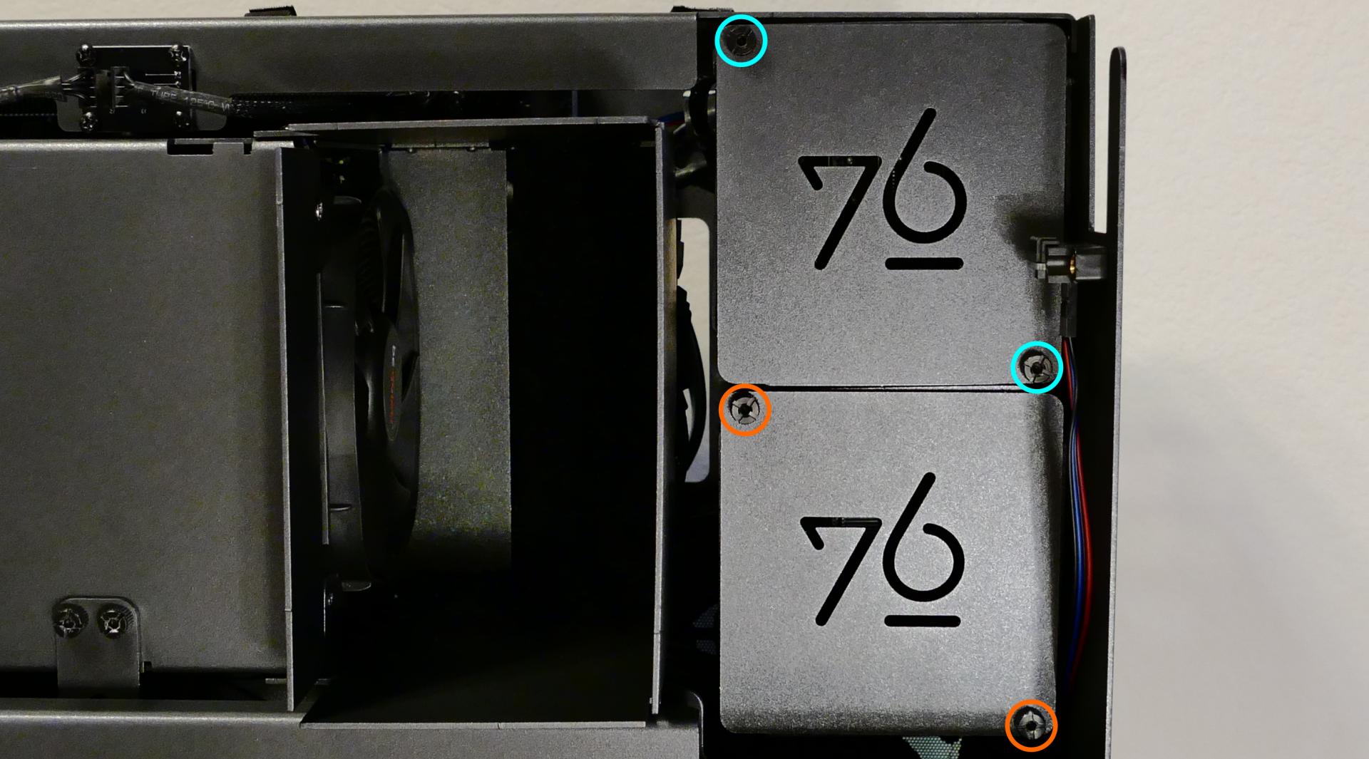
- Slide each 2.5" drive into one of the slots leading to the Thelio-IO boards.

Replacing the case fans:
Thelio Mega r1.0 has two case-mounted fans: one on the bottom, and one on the side next to the motherboard.
Tools required: Cross-head (Phillips) screwdriver
Time estimate: 15 minutes
Difficulty: Medium ●
Steps to replace the side case fan:
- Follow the steps above to remove the top case and remove the inner partition.
- Unscrew the fan's screws on the opposite side from where it's mounted.
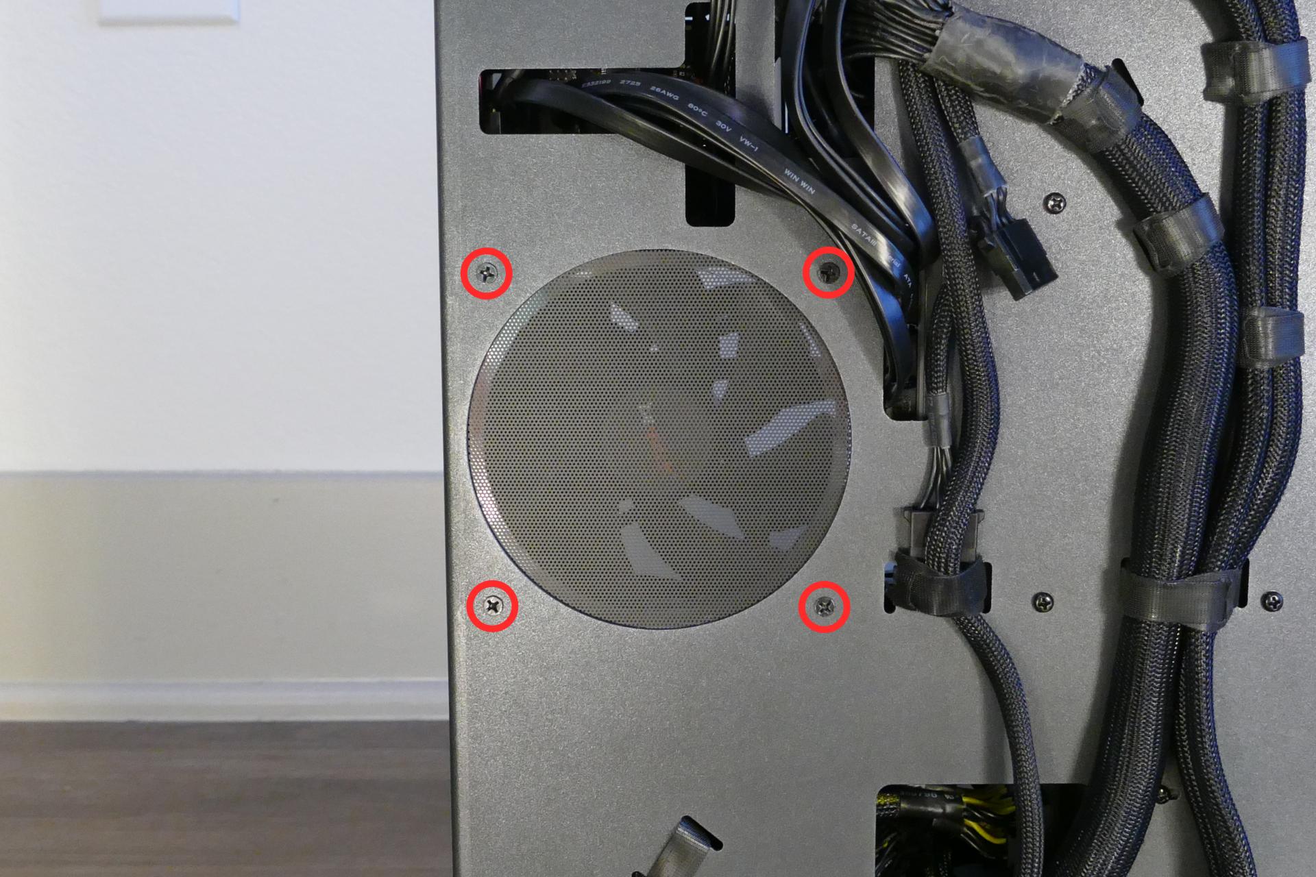
- Unplug and remove the fan.
- When replacing the fan, the components should be mounted in the following order:
- Chassis
- Dust filter
- Acrylic spacer
- Fan
Steps to replace the bottom case fan:
- Follow the steps above to remove the top case and remove the inner partition.
- Pull the rubber tabs until they come loose from the plastic pins holding the fan in place.
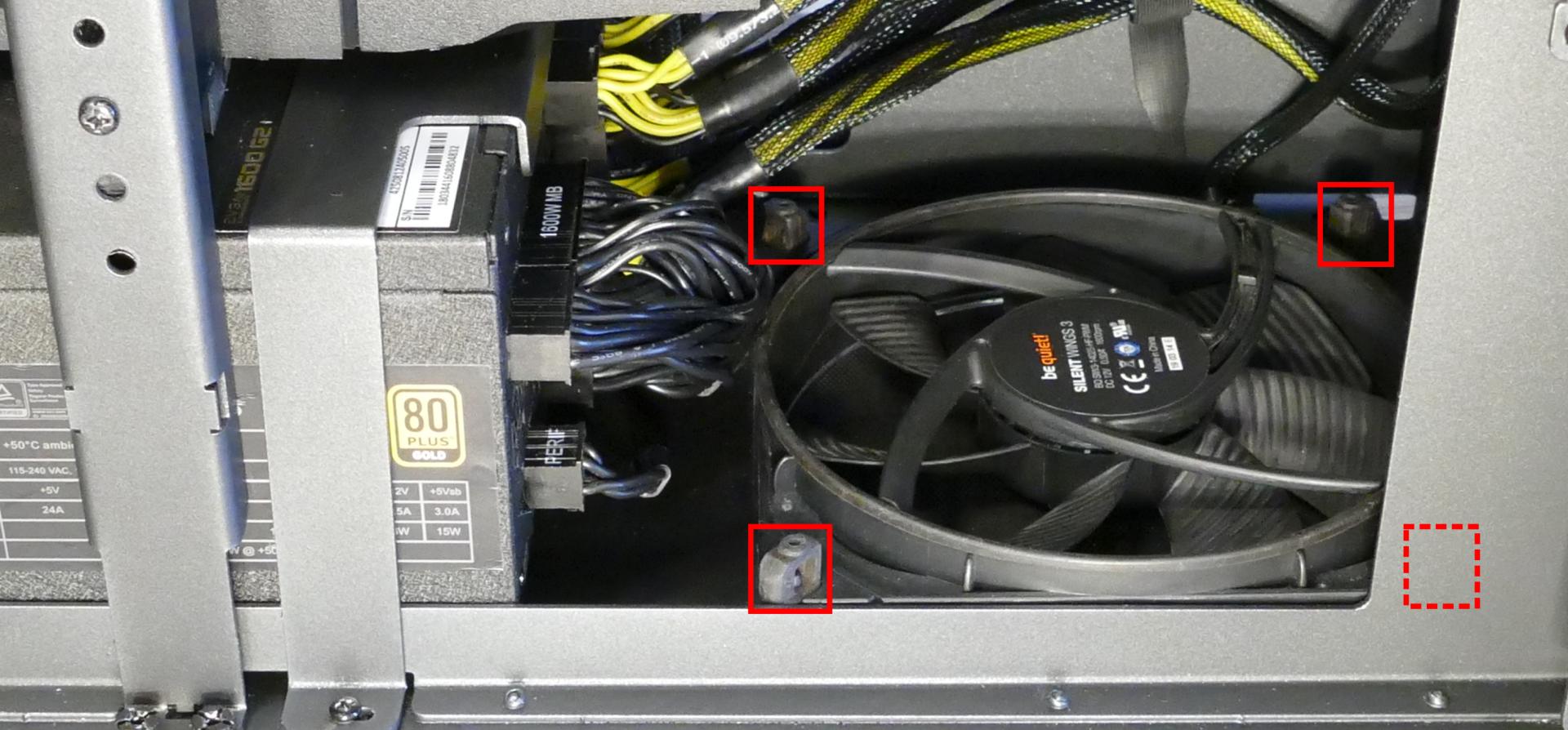
- When replacing the fan, hold the rubber tabs in place while pushing the plastic pins in from below the machine (it's necessary to tilt the machine when inserting the plastic pins.)
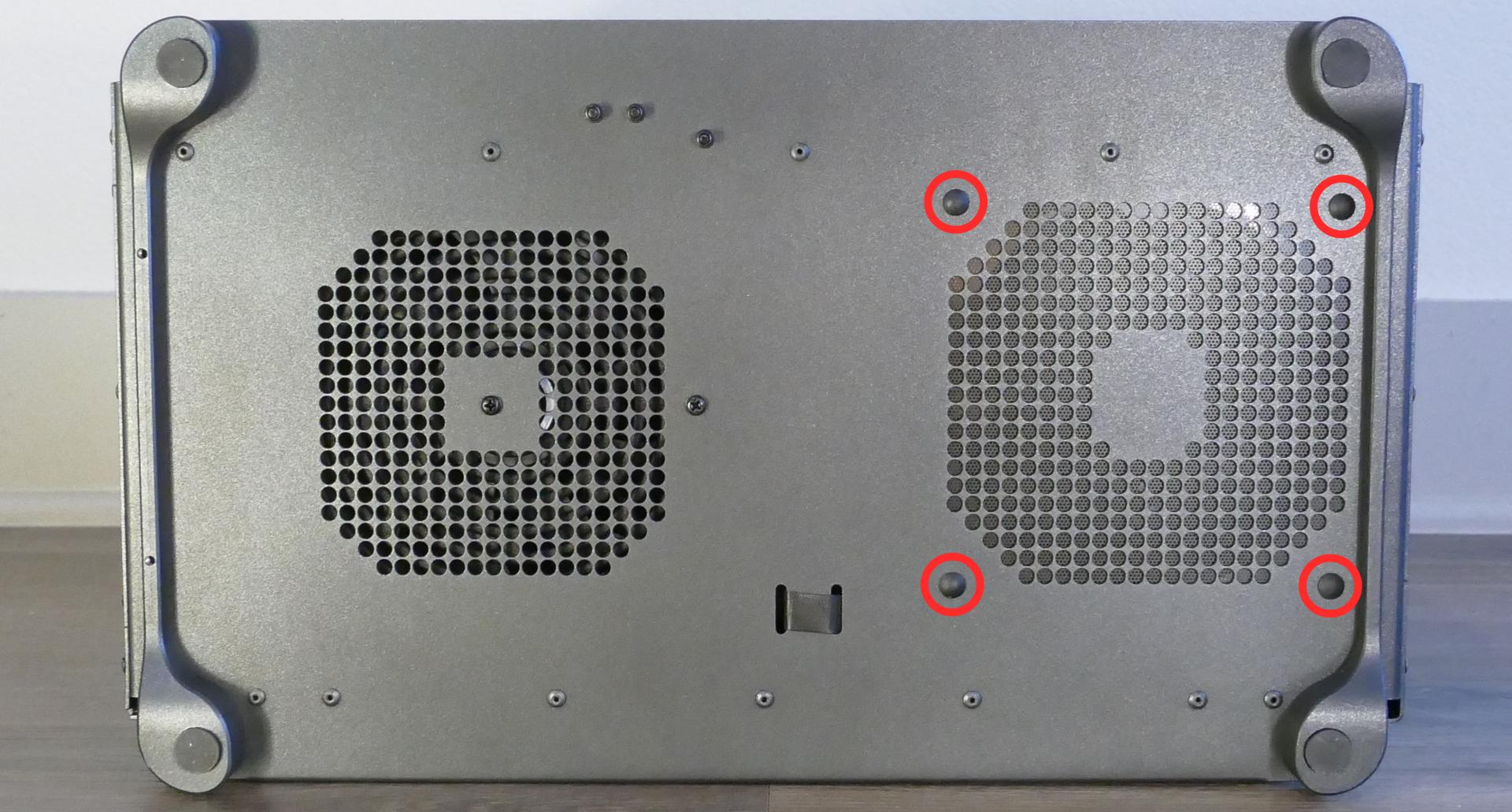
- The components should be mounted in the following order:
- Chassis
- Dust filter
- Acrylic spacer
- Fan
Replacing a GPU:
Thelio Mega supports up to four dual-slot GPUs, two with PCIe 4.0 x16 and two with PCIe 4.0 x8 (x16 cards will run at reduced bandwidth in the x8 slots.) Mixing NVIDIA and AMD GPUs is not recommended.
Tools required: Cross-head (Phillips) screwdriver
Time estimate: 15 minutes
Difficulty: Easy ●
Steps to replace a GPU:
- Follow the steps above to remove the top case and remove the inner partition.
- Unscrew the two back screws holding the PCIe bracket in place, then slide the PCIe bracket open.

- Unscrew the four screws holding the side GPU brace in place. Remove the brace.

- If you're removing a GPU, unplug the GPU power cable from the right side of the card. Hold down the latch on the connector while unplugging the cable.

- Hold the latch on the motherboard to free the PCIe connection, then pull the card out of the slot.
- If removing one of the inner GPUs, it may be necessary to remove one of the outer GPUs first in order to reach the latch.
- If space is tight, a long object such as a screwdriver can be used to press the latch.
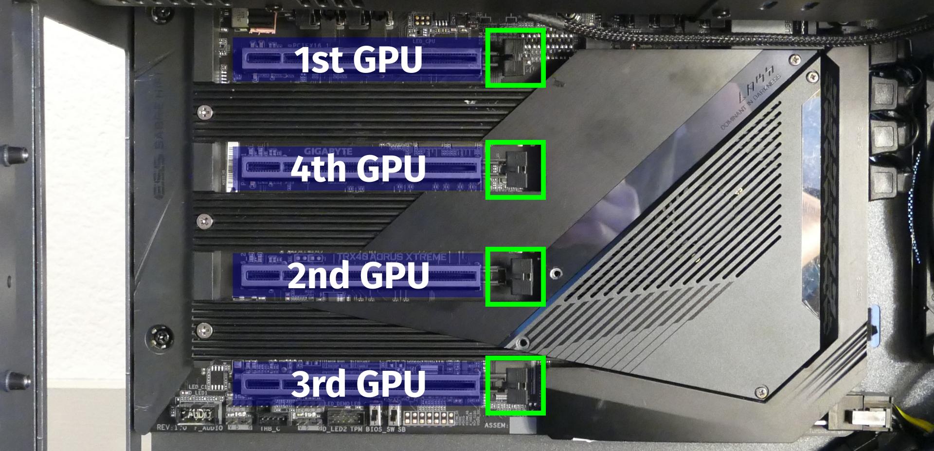
- When installing new GPUs, the slots should be utilized in the following order:
- Primary GPU: top slot.
- Secondary GPU: third slot from the top.
- Tertiary GPU: fourth slot from the top (bottom slot).
- Quaternary GPU: second slot from the top.
- After inserting the new GPU into its slot, connect the power cables.
- The maximum number of power cables are preinstalled in your system, but some may be tied back using velcro if the system shipped with less than four GPUs.
- Once all GPUs are installed, replace the side GPU brace, back PCIe bracket, inner partition, and top case.
- The side GPU brace includes a plastic piece sized to the GPUs that originally shipped with the system. To remove the plastic piece, unscrew it from the brace.

The plastic GPU brace's primary function is to prevent damage during shipping. The system can be run without the brace if it doesn't fit an upgraded card; the back PCIe bracket provides primary support for the GPUs.
Replacing the M.2 drives:
Thelio Mega has four M.2 slots, which support PCIe NVMe Gen 4 x4, PCIe NVMe Gen 3 x4, or SATA III. The following restrictions apply:
- Top M.2 slot: Supports sizes 22110, 2280, and 2260.
- Middle M.2 slot: Supports sizes 22110 and 2280.
- Bottom left M.2 slot: Supports sizes 22110 and 2280.
- Bottom right M.2 slot:
- Supports size 2280.
- If a SATA drive is installed in this slot, then 2.5" SATA ports 4 and 5 will be unavailable.
- If a PCIe NVMe drive is installed in this slot, then 2.5" SATA ports 4, 5, 6, and 7 will be unavailable.
Tools required: Cross-head (Phillips) screwdriver
Time estimate: 23 minutes
Difficulty: Medium ●
Steps to replace the M.2 drives:
- Follow the steps above to remove the top case, remove the inner partition, and remove the GPU brace and GPUs.
- Remove the M.2 heatsink covering the slots you wish to access.
- The top and middle M.2 slots are behind the top M.2 heatsink (highlighted cyan below).
- The bottom left and bottom right M.2 slots are behind the bottom M.2 heatsink (highlighted yellow below).
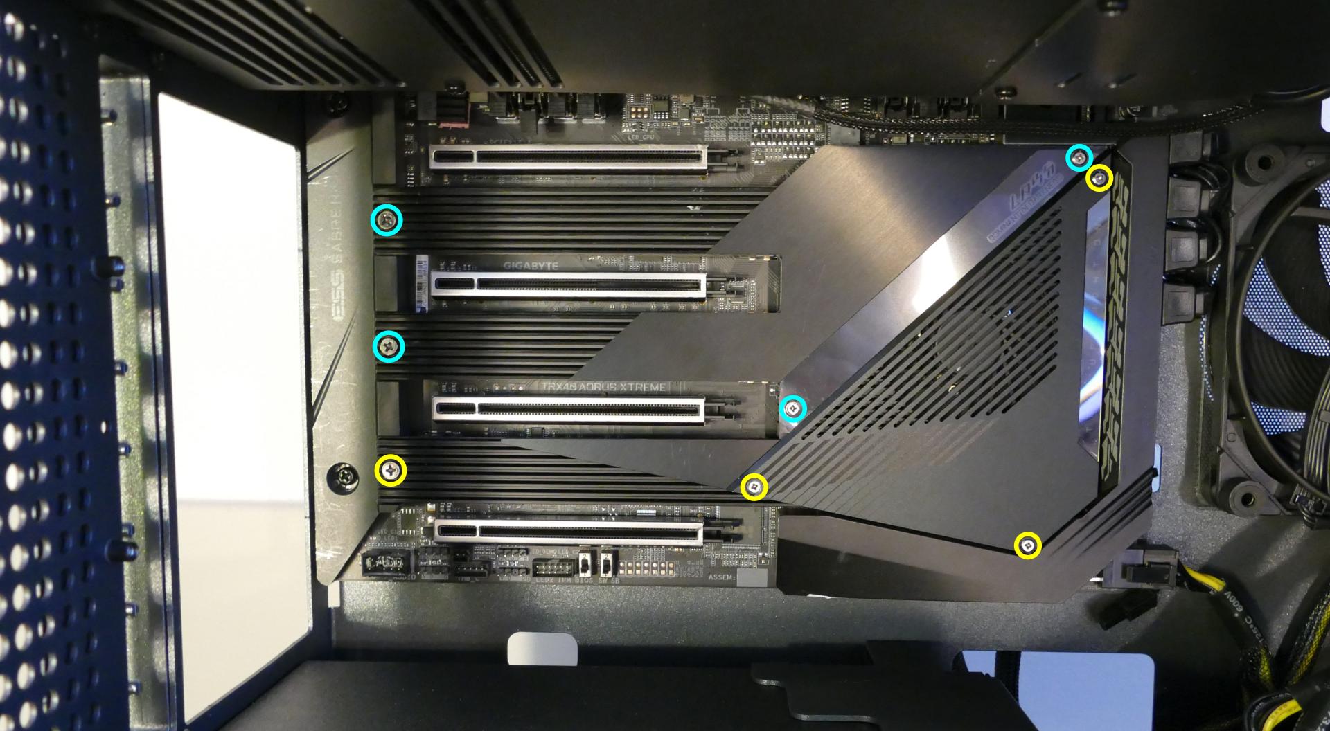
It may take some pressure to remove the heatsink and thermal tape from the M.2 drive. Pull slowly to avoid breaking the thermal tape.
- Unscrew the retainer screw opposite the M.2 slot.

- Remove the existing M.2 drive by pulling it out of the slot.
- Insert the new M.2 drive into the slot and hold it in place.
- Replace the retainer screw.
- If utilizing a slot for the first time, peel the plastic backing off of the heatsink to expose the double-sided thermal tape for that slot.
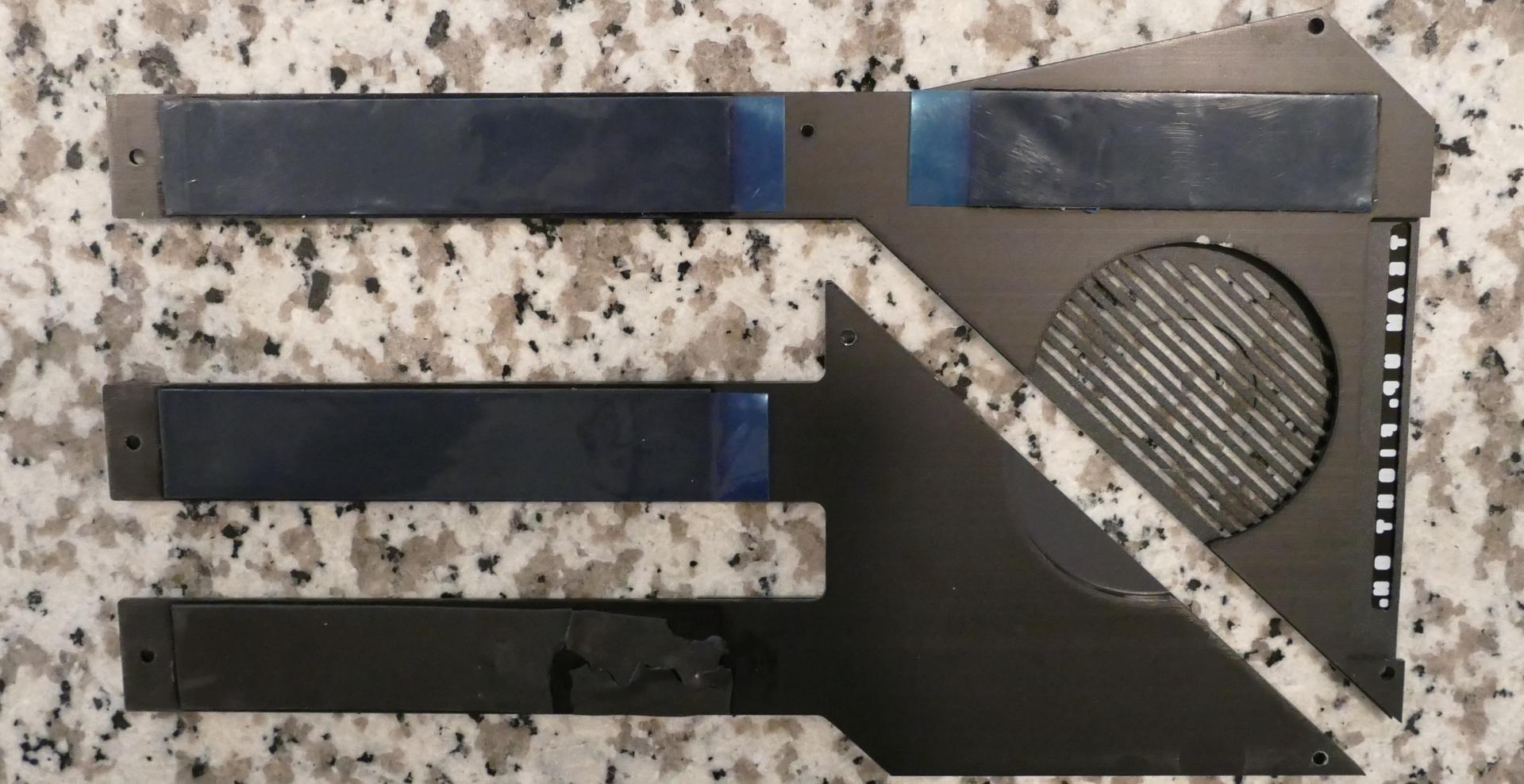
- Replace the M.2 heatsinks, GPUs, GPU brace, inner partition, and top case.
Removing the CPU duct:
The CPU duct guides airflow through the CPU coolers. It covers the CPU and RAM slots on the motherboard.
Tools required: Cross-head (Phillips) screwdriver (optional)
Time estimate: 7 minutes
Difficulty: Easy ●
Steps to remove the CPU duct:
- Follow the steps above to remove the top case, remove the inner partition, and remove the GPU brace.
- Unplug the connectors for the two CPU duct-mounted fans.

- Unscrew the four back screws holding the CPU duct in place.
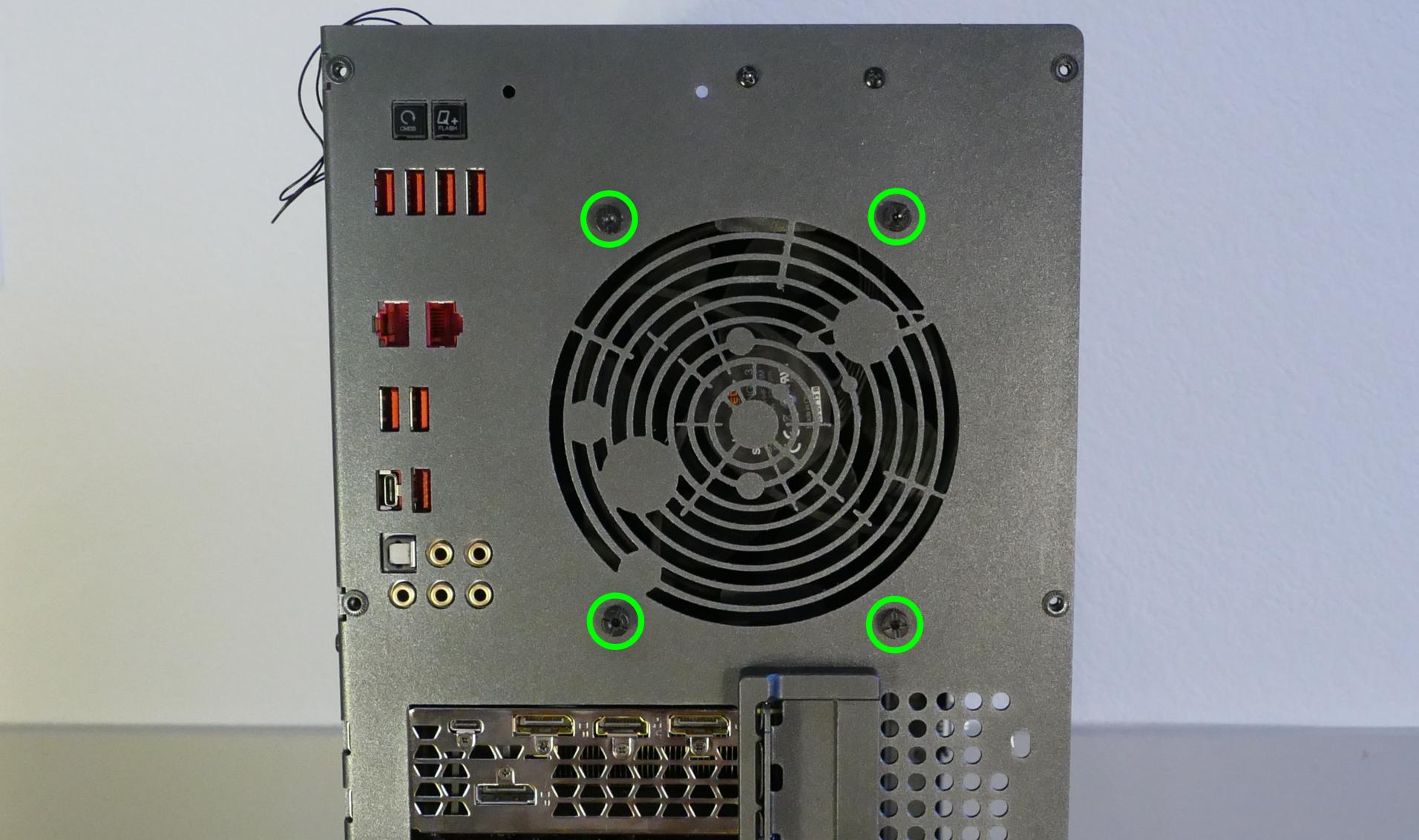
- Pull the CPU duct away from the machine.
Replacing the RAM:
Thelio Mega r1.0 supports up to 256GB (8x32GB) of RAM. The RAM sticks are Unregistered/Unbuffered ECC DDR4 DIMMs running at a speed of 3200MHz. If you've purchased new RAM, need to replace your RAM, or are reseating your RAM, follow these steps.
Tools required: Cross-head (Phillips) screwdriver (optional)
Time estimate: 20 minutes
Difficulty: Medium ●
Steps to replace the RAM:
- Follow the steps above to remove the top case, remove the inner partition, remove the GPU brace, and remove the CPU duct.
- To remove an existing RAM stick, flip the bottom latch down away from the stick, then pull the stick out of the slot, starting from the bottom edge. (The top of the RAM slot does not move.)

The CPU cooler has been removed for better visibility in the above photo; removing the CPU cooler is not required to access all eight of the RAM slots.
- Make sure the tab on the bottom of the slot is open (pulled downwards), then insert the new RAM (or re-seat the existing RAM) into the slot.
- The RAM stick will only fit in one direction. On the left side of the CPU, the larger group of pins goes on bottom; on the right side of the CPU, the larger group of pins goes on top.
- Use the following guide for placement of the RAM sticks:

- Replace the CPU duct, GPU brace, inner partition, and top case.
Removing the top crossbar:
The top crossbar provides a brace for the outer case. It needs to be removed when replacing certain components (such as the top Thelio-IO board and the CPU cooler-mounted fan.)
Tools required: Cross-head (Phillips) screwdriver
Time estimate: 7 minutes
Difficulty: Easy ●
Steps to remove the top crossbar:
- Follow the steps above to remove the top case.
- Unplug the two top fan connectors.

- Unscrew the four screws holding the top crossbar in place (two on the front of the machine, and two on the back.)
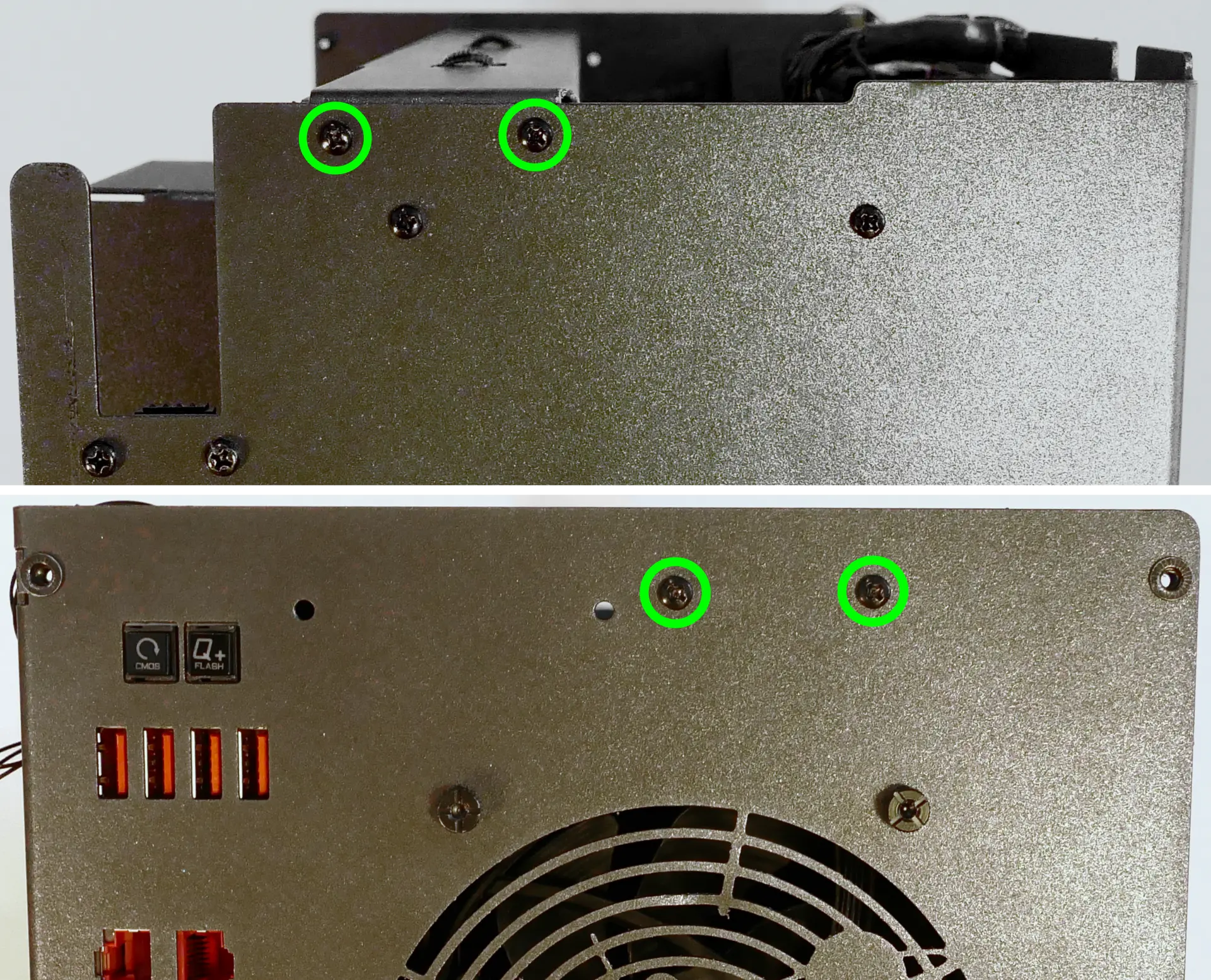
- Lift the top crossbar out of the system. (It is not necessary to unplug the fan cable underneath the top crossbar unless you are replacing that cable or the Thelio-IO board it plugs into.)
Replacing the CPU fans:
Thelio Mega r1.0 contains three CPU fans. Two are mounted on the CPU duct, and one is mounted on the cooler.
Tools required: Cross-head (Phillips) screwdriver
Time estimate: 25 minutes
Difficulty: Medium ●
Steps to replace the duct-mounted CPU fans:
- Follow the steps above to remove the top case, remove the inner partition, remove the GPU brace, and remove the CPU duct.
- To remove the back CPU duct fan, unscrew the four screws holding the fan brackets into the duct (highlighted green below).

- Free the cable from the velcro loop (highlighted blue above), then unscrew the four screws holding the brackets onto the fan.
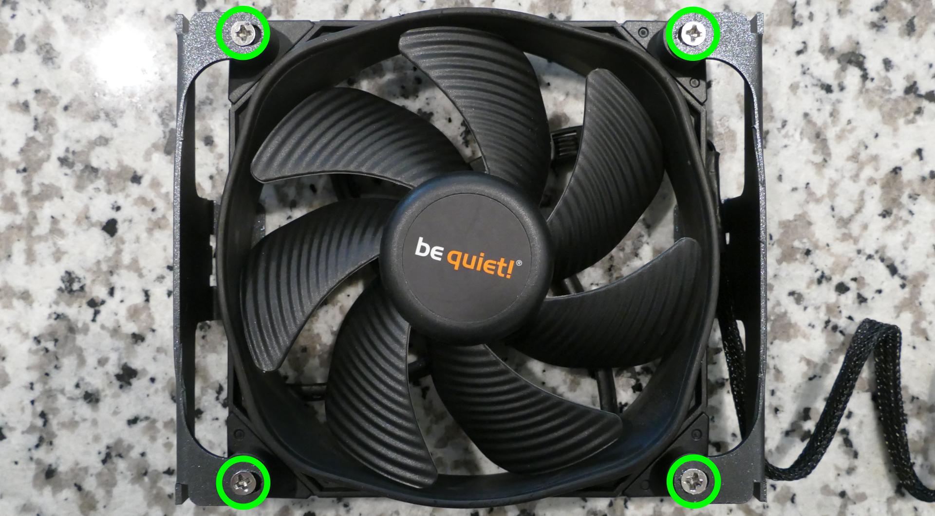
- To remove the front CPU duct fan, unscrew the four screws attaching the front of the duct to the back (highlighted red above).
- Then, unscrew the four screws attaching the fan to the duct.
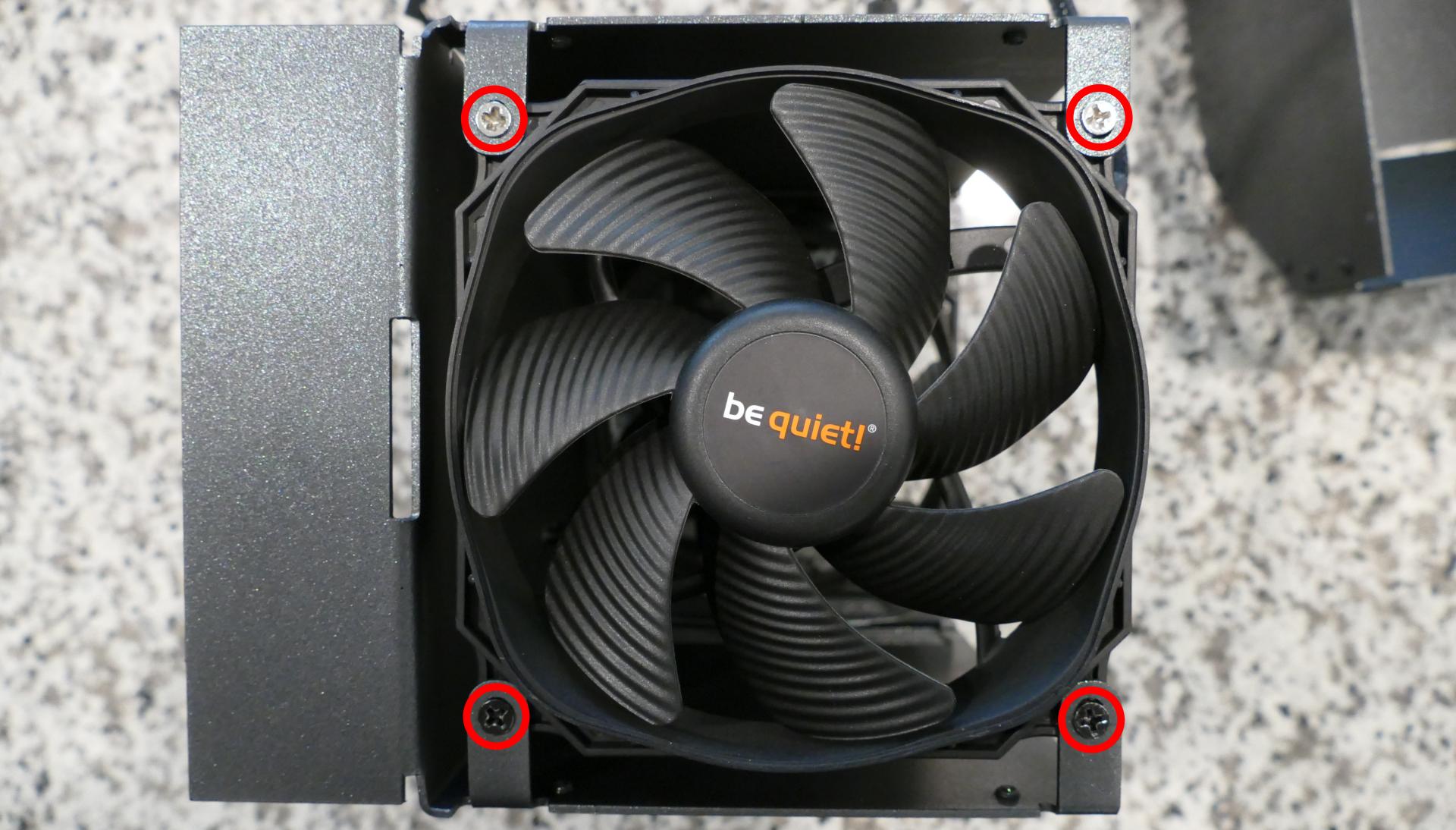
Steps to replace the cooler-mounted CPU fan:
- Follow the steps above to remove the top case, remove the inner partition, remove the GPU brace and GPUs, remove the CPU duct, and remove the top crossbar.
- Pull the corners of the fan's top clip away from the heatsink it's held to.
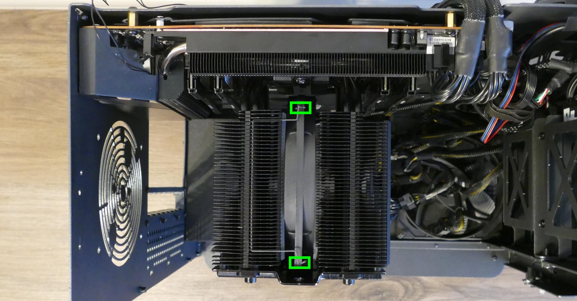
- Repeat the process for the bottom clip, then slide the fan down and out of the CPU cooler.
- Unplug the fan from the Thelio-IO board.
- The CPU cooler fan plugs directly into the
CPUOUT0port on the bottom Thelio-IO board.
- The CPU cooler fan plugs directly into the
- When reinstalling the CPU fans, all three fans should be oriented so the side with the non-spinning cover faces the back of the machine, while the spinning side faces the front of the machine.
Replacing the CPU cooler and CPU:
The CPU cooler dissipates heat from the CPU to the heatsink, where the CPU fans expel it from the system. Depending on your climate and the age of the machine, replacing the thermal paste between the CPU and the cooler/heatsink may help the system run cooler.
The CPU uses an AMD sTRX4 socket.
Tools required: Cross-head (Phillips) screwdriver (long), torx screwdriver, thermal paste
Time estimate: 35 minutes
Difficulty: High ●
Steps to remove the CPU cooler/thermal paste:
- Follow the steps above to remove the top case, remove the inner partition, remove the GPU brace and GPUs, remove the CPU duct, remove the top crossbar, and remove the cooler-mounted CPU fan.
- Unscrew the two screw access covers from the holes in the cooler plate.

- While holding the cooler in place so it doesn't fall, reach a cross-head (Phillips) screwdriver through the holes in the cooler plate and loosen the two screws holding the cooler onto the mounting bracket.
- The cooler will come away from the CPU.
- The two screws on the crossbar attaching the CPU cooler to the mounting bracket are held to the crossbar with small rubber rings.
- If the rubber rings become detached, slide them back onto the screws before reinstalling the cooler.

- Using a paper towel, clean the existing thermal paste off of the heatsink and CPU. You may also use a small amount of rubbing alcohol if the old paste is dried or difficult to remove.
Steps to replace the CPU:
- Unscrew the four screws holding the two mounting brackets onto the motherboard.
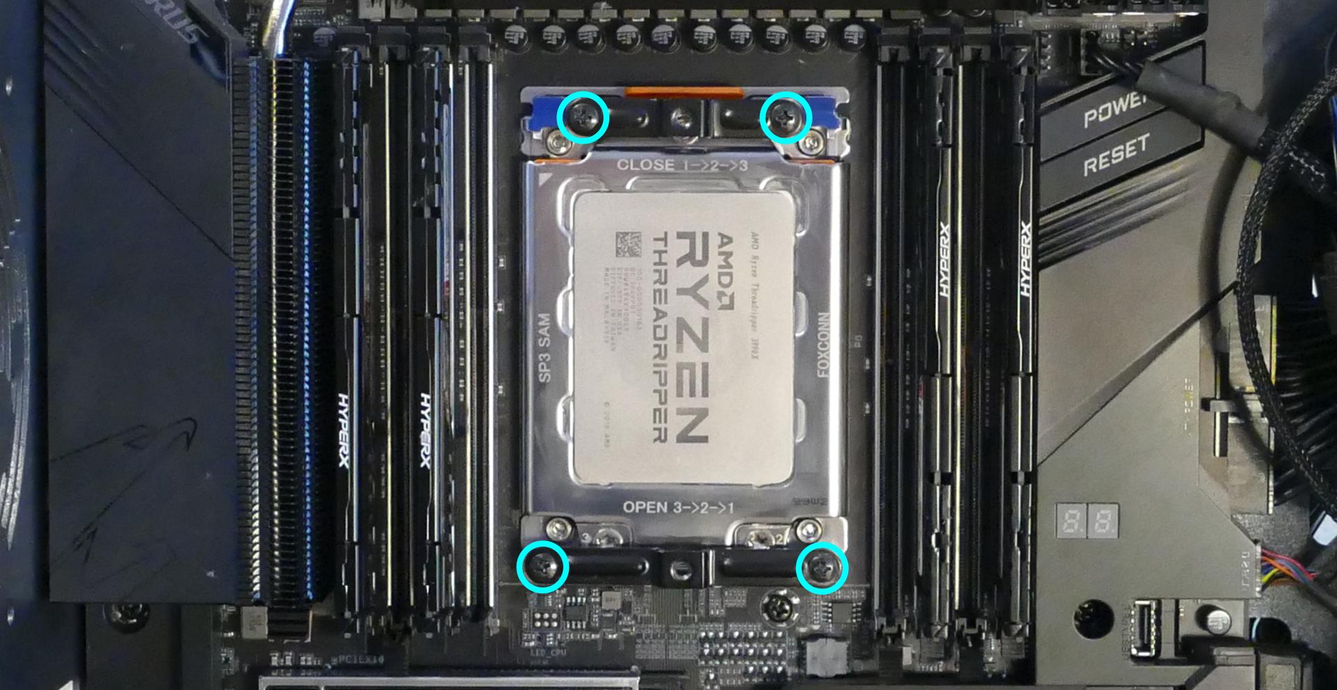
- The black plastic standoff covers will also come loose once the mounting bracket screws are removed. Remember to replace the black plastic standoff covers when reinstalling the mounting brackets.

- Using the torx screwdriver, loosen the three CPU cover screws in reverse order (starting with #3, then #2, and finally #1.)
- These screws will not come out of the CPU cover when they are fully loosened.
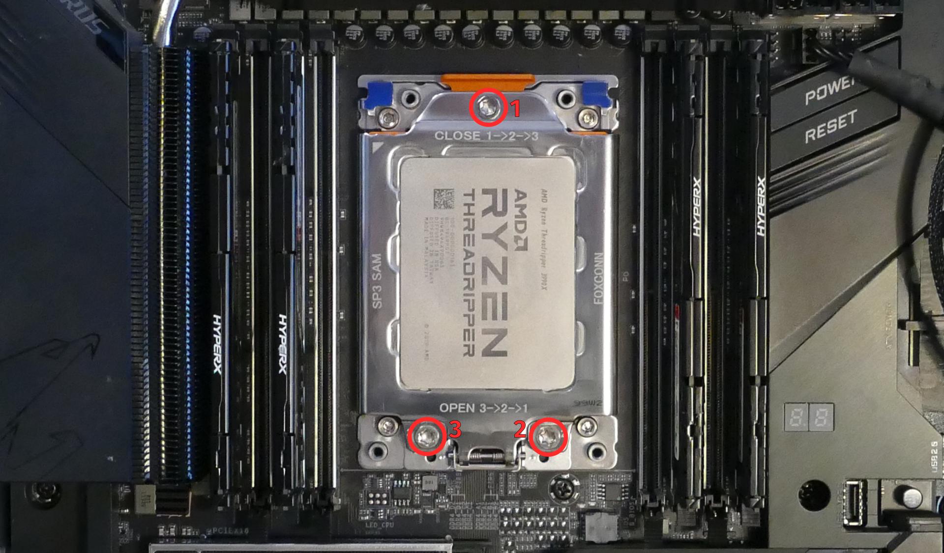
- The CPU cover will lower once its screws are loosened. There may be additional remnants of thermal paste underneath the CPU cover.
- Pull the blue metal tabs away from the motherboard to flip the CPU holder down on top of the CPU cover.
- Caution: Be careful not to bend any of the gold pins on the CPU socket, and do not touch the gold pads on the CPU.
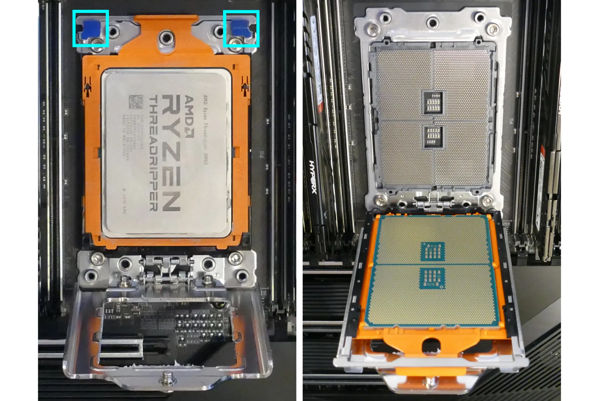
- Pull the orange tab to slide the CPU out of the CPU holder.
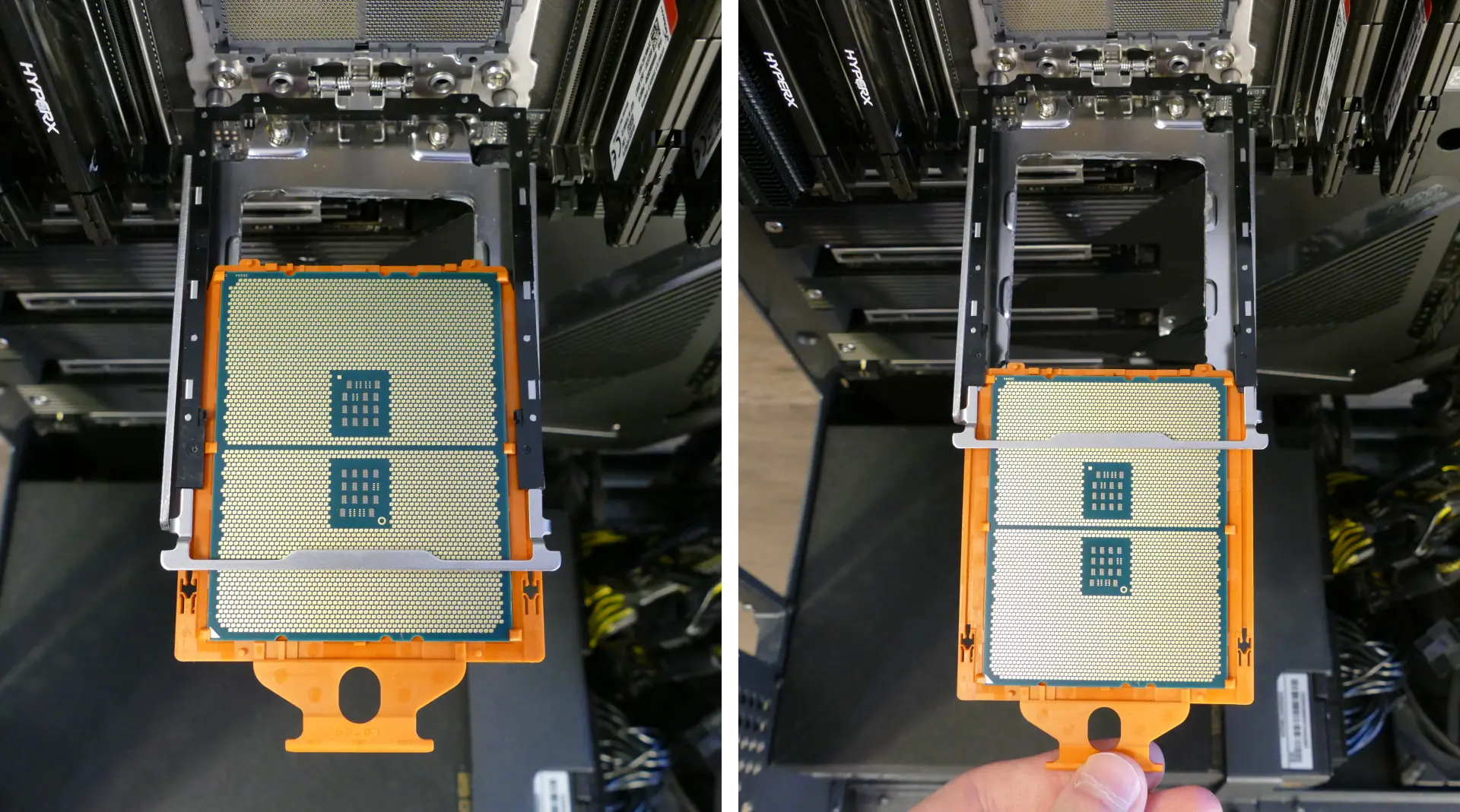
- Each AMD Threadripper CPU is shipped inside of an orange plastic clip, so it should not be necessary to remove the CPU from the orange plastic clip. However, if desired (such as to clean off additional thermal paste), the plastic clip can be removed by pulling it back near each of the tabs holding the CPU in place.
- When reinstalling the CPU into the clip, be sure to match the original orientation, with the triangle on the CPU closest to the tab on the plastic clip.
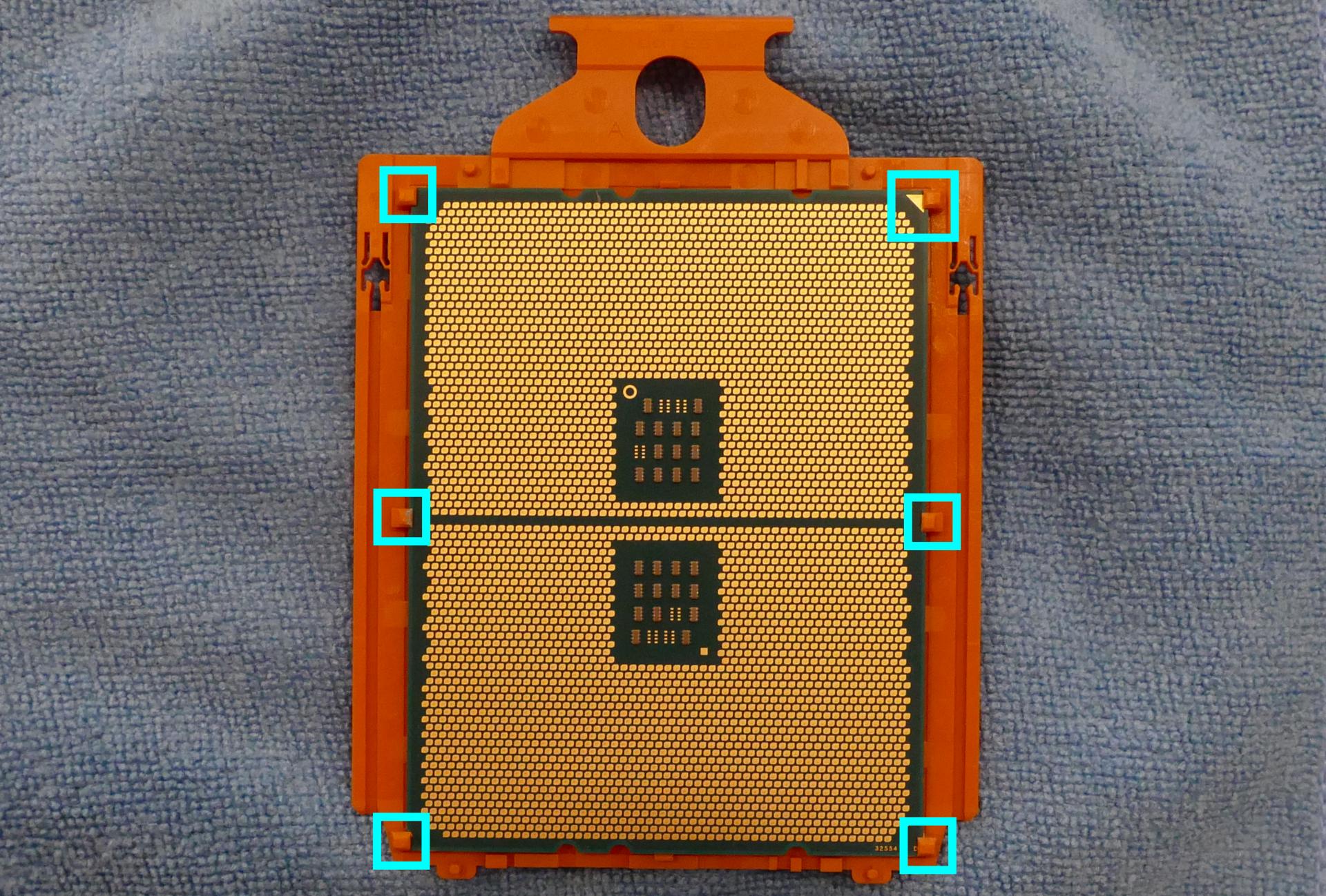
- Slide the new CPU into the CPU holder. Make sure the orange CPU clip aligns properly with the black rails on the CPU holder.
- Fold the CPU holder up onto the motherboard until it clicks into place, fold the CPU cover back into place, and tighten the CPU cover screws in ascending order (starting with #1, then #2, and finally #3.)
- Screw the two mounting brackets for the CPU cooler back onto the motherboard (the smaller bracket goes above the CPU, while the larger bracket goes below the CPU.)
Steps to install the thermal paste/CPU cooler:
- Place a line of thermal paste onto the CPU.

- Slide the CPU cooler crossbar on the back of the heatsink until the grooves are positioned correctly.
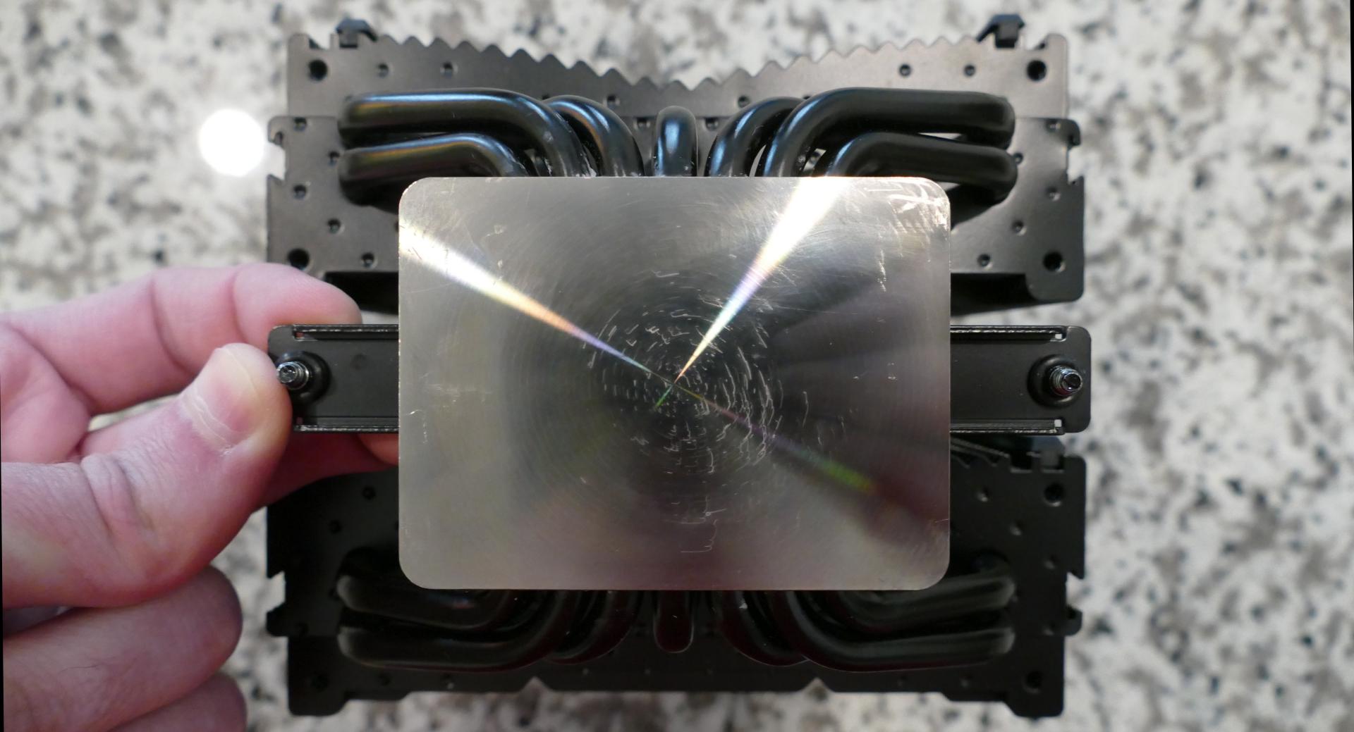
- While holding the crossbar onto the heatsink, hold the heatsink in position and use the long cross-head screwdriver (inserted through the holes in the cooler plate) to screw each end of the crossbar into one of the mounting brackets.
- The logo on the cooler should be upright.
- The rubber strips on the inside of the cooler should be closest to the back of the machine, while the rubber strips on the outside of the cooler should be closest to the front of the machine.
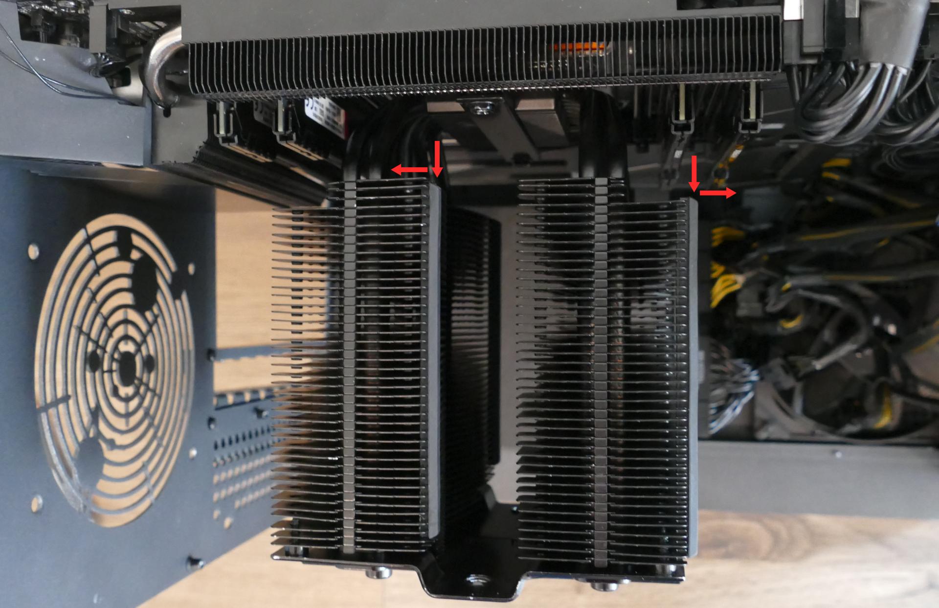
- Reinstall the cooler-mounted CPU fan, top crossbar, CPU duct, GPUs, GPU bracket, inner partition, and top case.
Replacing the power supply:
The power supply unit (PSU) is modular and can be replaced with another unit of the same model. Different models may not be compatible with the cabling pre-installed in the Thelio Mega.
Tools required: Cross-head (Phillips) screwdriver
Time estimate: 30 minutes
Difficulty: High ●
Steps to replace the power supply:
- Follow the steps above to remove the top case, remove the inner partition and remove the GPU brace and GPUs.
- Unplug all of the modular cabling from the back of the PSU.
- Some of the cables may be easier to unplug after the PSU has been unscrewed/removed from the case.
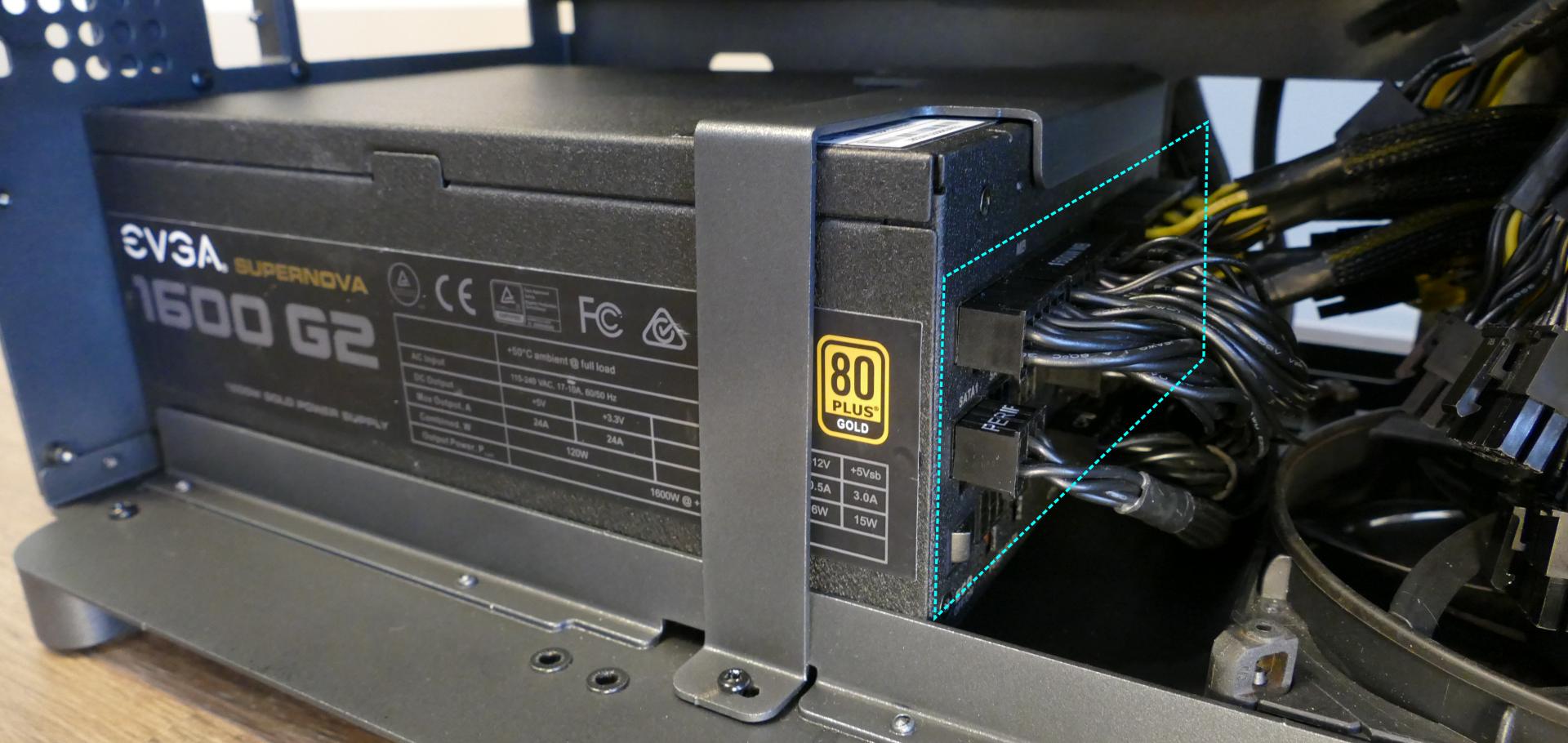
- Unscrew the PSU bracket from the reverse side of the case.
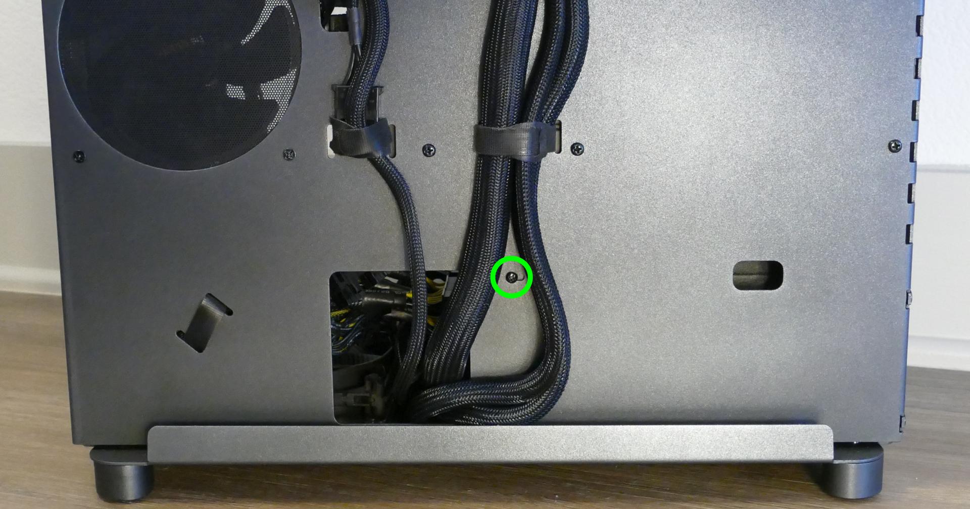
- Unscrew the PSU bracket from the bottom of the case.
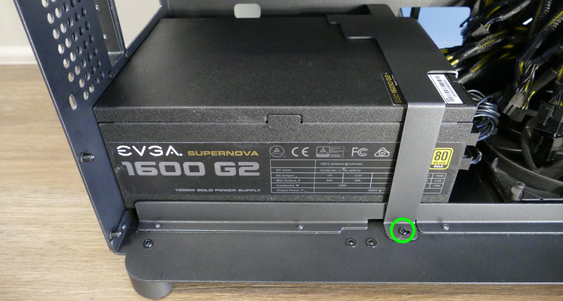
- Remove the PSU bracket.
- Unscrew the four screws holding the PSU in from the back of the case.
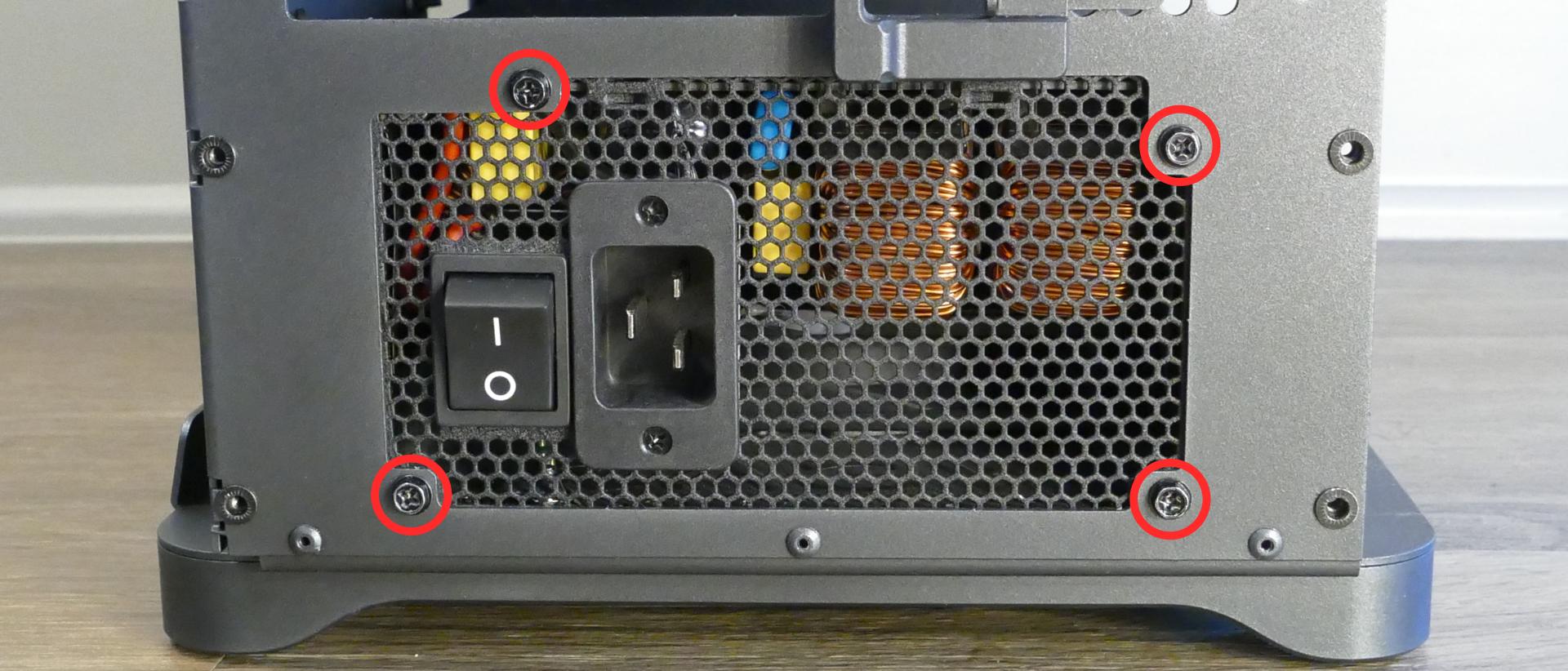
- Remove/replace the PSU. Set the replacement PSU on top of the two rubber posts that hold it at the correct height.
- The replacement PSU should be installed with the fan facing the bottom of the case.
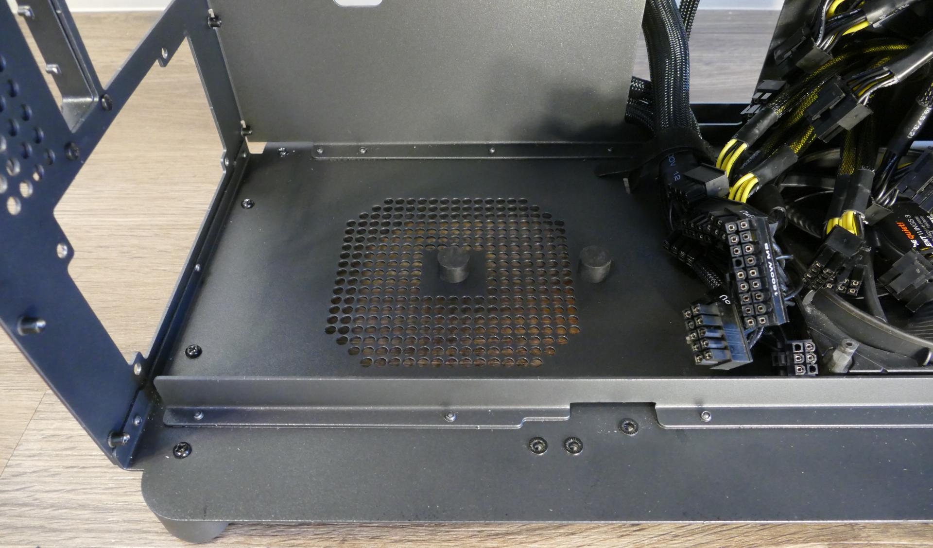
- After screwing in the replacement PSU and replacing the PSU bracket, use the labels and pin counts on the cables and ports to ensure the power cables are reconnected in the proper locations.
- Remember that not all of the available connectors will plug into the PSU-- eight connectors (on four cables) are to be plugged into the GPUs.
- If the replacement PSU has an "ECO Mode" switch, make sure it is switched on.

Replacing the side fans:
Thelio Mega r1.0 has two intake fans mounted on the inner partition. The fans can be replaced if they become defective/noisy.
Tools required: Cross-head (Phillips) screwdriver
Time estimate: 15 minutes
Difficulty: Easy ●
Steps to replace the side fans:
- Follow the steps above to remove the top case and remove the inner partition.
- Pull the rubber tabs until they come loose from the plastic pins holding the fan in place.
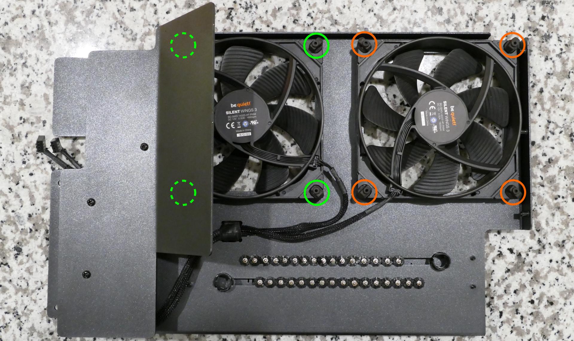
- Pull the end of the fan cable through the opening and release any velcro strips that are holding it in place.
- When replacing the fan, hold the rubber tabs in place while pushing the plastic pins in from the opposite side.
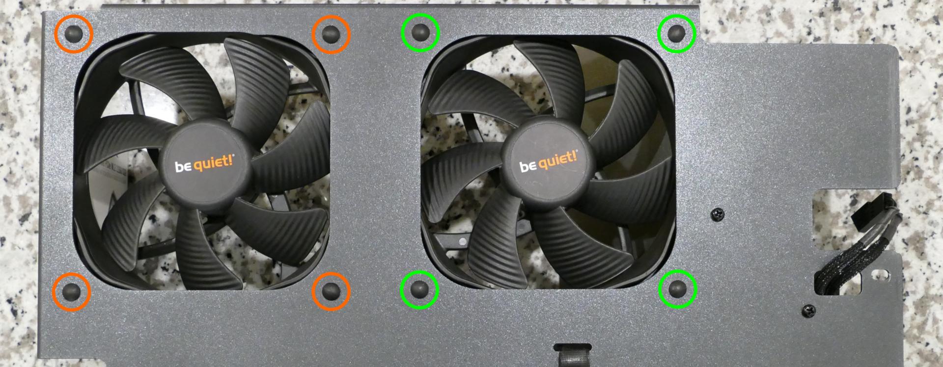
Replacing the Thelio-IO boards:
Tools required: Cross-head (Phillips) screwdriver
Time estimate: 25 minutes
Difficulty: High ●
The Thelio-IO board handles the front power button, fan control, and 2.5" SATA connectors for the system. If one of the Thelio-IO boards becomes defective, it can be replaced using the instructions below.
- Follow the steps above to remove the top case, remove the inner partition, remove the top crossbar, and remove the front cover from the 2.5" drive cage for the Thelio-IO board that is being replaced.
- Use the cutouts on the opposite side of the chassis to unplug all cabling from the Thelio-IO board that is being replaced.
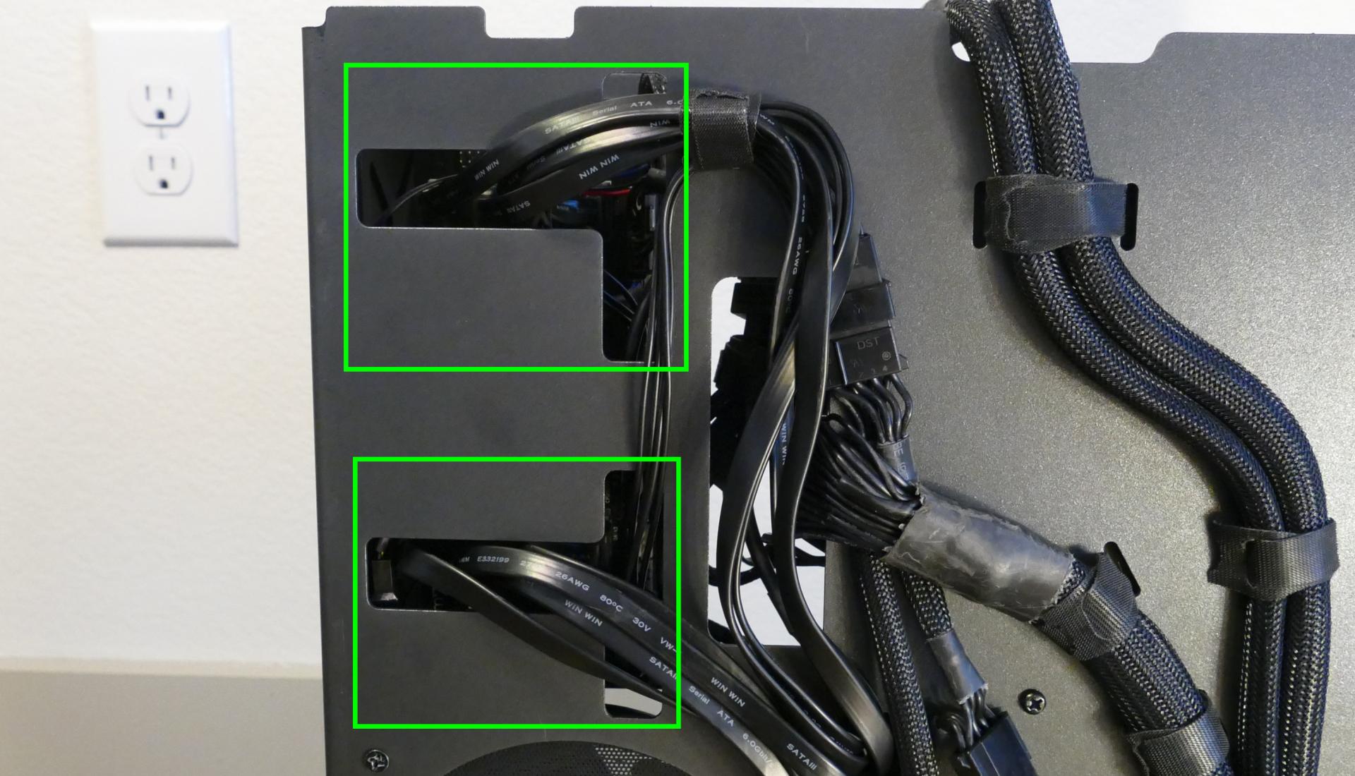
- Unscrew the two screws on the top of the upper drive cage (for the top Thelio-IO board) or the bottom of the lower drive cage (for the bottom Thelio-IO board).
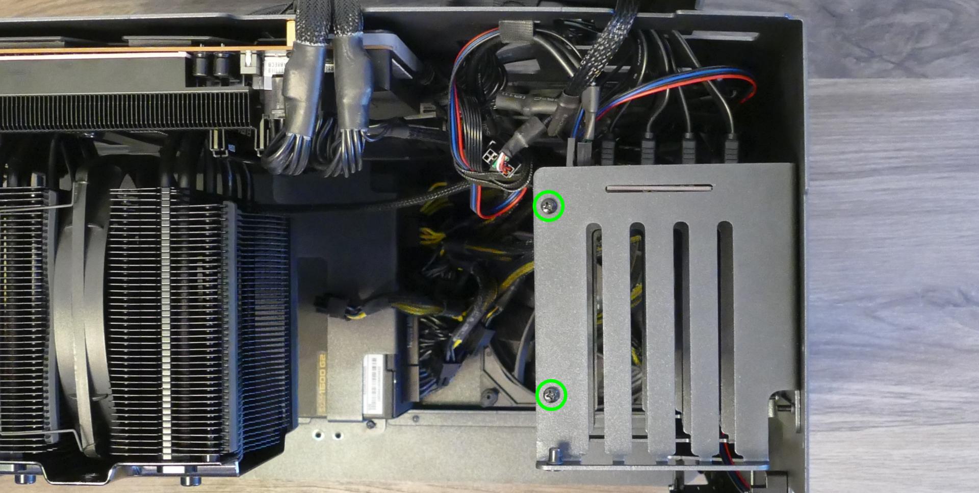
- While pulling the loose side of the drive cage away from the Thelio-IO board, move the board back and out of the drive cage.
- Place the new Thelio-IO board into the drive cage and replace the screws and wiring.
Troubleshooting the power button:
If the front power button doesn't power the machine on or doesn't light up when the system is powered on, try the following troubleshooting steps:
- Ensure the system powers on normally using the internal power button.
- Reseat the front power button to ensure it's making proper contact.
- Check the wiring for the front power button.
- Replace the front power button, if necessary.
Tools required: Cross-head (Phillips) screwdriver (optional)
Time estimate: 20 minutes
Difficulty: Medium ●
Steps to power the machine on using the internal power button:
- Follow the steps above to remove the top case and remove the inner partition.
- Ensure the system is plugged into power, and the power supply switch is in the 1 (On) position.
- Push the small button labeled
B0on the top Thelio-IO board.

- If the Thelio-IO
B0button powers the machine on, then the issue is either the front power button or its connection to the Thelio-IO board. Check the front power button wiring. - If the Thelio-IO
B0button does not work, press thePowerbutton in the top right of the motherboard.
- If the motherboard
Powerbutton works, but the Thelio-IOB0button does not work, then the issue is either the Thelio-IO board or its connection to the motherboard. Check the wiring between the Thelio-IO board and the motherboard.- The second Thelio-IO board's power ports can be used if the first board becomes defective.
- If the motherboard
Powerbutton does not work, then the issue may be the motherboard, or it may be the power supply or its connection to the motherboard. Ensure all connections are plugged in properly and that the power supply is switched to the 1 (On) position.
Steps to check the front power button wiring:
- Follow the steps above to remove the top case, remove the inner partition, remove the GPU brace, and remove the CPU duct.
- On the back of the power button, the four pins should be connected to the four-wire connector as follows:

- On the front power button receptacle, the four-pin connector should have the red wire on the left and the black wire on the right.

- The front power button receptacle should plug into the
PFPDport on the top Thelio-IO board, with the red wire on the bottom and the black wire on the top.

- The
PMBDport on the Thelio-IO board should connect to an adapter:- The red wire on the four-port connector should be on the bottom on the Thelio-IO board.
- The other side of the cable connects to the adapter, with the red wire on the top left, the blue pair immediately following the red pair, and a black wire on the right.

- The adapter should connect to the
F-PANEL(front panel) input on the motherboard.

Steps to replace the power button:
- Follow the steps above to remove the top case.
- Follow the instructions in the Replace the Thelio Power Button support article.
Troubleshooting the Thelio-IO USB connection:
The Thelio-IO boards connect to the motherboard's USB headers for firmware updates and fan control within the host OS. If the fans seem to be stuck on full blast, check the Thelio-IO USB connections.
Tools required: Cross-head (Phillips) screwdriver (optional)
Time estimate: 15 minutes
Difficulty: Medium ●
Steps to check the USB wiring:
- Follow the steps above to remove the top case, remove the inner partition, remove the GPU brace, and remove the CPU duct.
- Two of the Thelio-IO boards have
USB0ports. The port on each board connects to a cable (labeledUSB) with the red wire on the bottom.

- The two internal USB cables plug into the motherboard's USB headers.

Thelio Mira (thelio-mira-b4-n3)
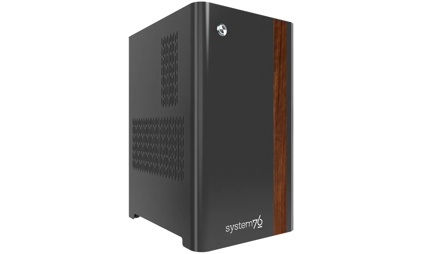
The System76 Thelio Mira is a desktop with the following specifications:
- Processor options
- Supports Intel 14th generation (Raptor Lake) CPUs
- Motherboard
- Gigabyte Z790 Aorus Elite AX running System76 Firmware (non-open)
- Intel Z790 Express Chipset
- Daughterboard
- Thelio Io board running open-source firmware
- Version 2.3
- Thelio Io board running open-source firmware
- Graphics options
- Configured with up to one dedicated GPU
- Factory configurations limited to one GPU
- Primary GPU slot:
- PCIe 5.0 x16
- Up to 4-slot height
- Secondary GPU slot:
- PCIe 4.0 x4
- Fits physical x16 cards, runs at x4 bandwidth
- Up to 2-slot height (if third slot is empty)
- PCIe 4.0 x4
- GPU size:
- Internal clearance: 358.00mm
- Recommended maximum length: 348.00mm
- Tested with the following GPUs:
- NVIDIA GeForce RTX 4090
- 3x DisplayPort 1.4a
- 1x HDMI 2.1a
- NVIDIA GeForce RTX 4080 Super
- 3x DisplayPort 1.4a
- 1x HDMI 2.1
- NVIDIA GeForce RTX 4070 Ti Super
- 3x DisplayPort 1.4a
- 1x HDMI 2.1
- NVIDIA GeForce RTX 4060 Ti
- 3x DisplayPort 1.4a
- 1x HDMI 2.1
- AMD Radeon RX 7900 GRE
- 2x DisplayPort 2.1
- 2x HDMI 2.1a
- 1x USB Type-C (DisplayPort 2.1 signal)
- AMD Radeon RX 7600
- 2x DisplayPort 2.1
- 2x HDMI 2.1a
- Integrated Graphics (dependent on CPU selection)
- Core i7-14700K, Core i9-14900K, Core i9-14900KS:
- Intel UHD Graphics 770
- 1x HDMI 2.1
- Intel UHD Graphics 770
- Core i5-14400:
- Intel UHD Graphics 730
- 1x HDMI 2.1
- Intel UHD Graphics 730
- Core i7-14700K, Core i9-14900K, Core i9-14900KS:
- NVIDIA GeForce RTX 4090
- Configured with up to one dedicated GPU
- Expansion
- 1x PCIe 5.0 x16 (primary GPU slot)
- 1x PCIe 4.0 x4 (secondary GPU slot)
- Fits physical x16 cards, runs at x4 bandwidth
- 1x PCIe 3.0 x4
- Fits physical x16 cards, runs at x4 bandwidth
- Memory
- Up to 128GB (4x32GB) dual-channel DDR5 DIMMs @ 4000 MHz
- 64GB (2x32GB) and less runs @ 4800 MHz
- Tested with the following RAM modules (may ship with other tested modules):
- Crucial CT32G48C40U5 (32GB/stick)
- Up to 128GB (4x32GB) dual-channel DDR5 DIMMs @ 4000 MHz
- Networking
- 1x 2.5-Gigabit Ethernet (Realtek RTL8125)
- Wi-Fi 6E + Bluetooth 5.2 (Intel AX211)
- Power
- C13 power cord
- 850W PSU
- 80+ Gold Efficiency
- Tested with the following PSU models (may ship with other tested models):
- Sound
- Back:
- 3.5mm mic in
- 3.5mm line out
- S/PDIF out
- Top:
- 3.5mm mic in
- 3.5mm line out
- Up to 7.1-channel audio output
- Realtek ALC897 audio chipset
- HDMI, DisplayPort, USB-C DisplayPort audio (depending on GPU)
- Back:
- Storage
- 4x M.2 (PCIe NVMe Gen 4) SSDs
- 2x 2.5" SATA III
- USB
- Back ports:
- 1x USB 3.2 Gen 2x2 (Type-C)
- Does not support Thunderbolt or DisplayPort over USB-C.
- 2x USB 3.2 Gen 2 (Type-A)
- 3x USB 3.2 Gen 1 (Type-A)
- 4x USB 2.0 Type-A (Type-A)
- 1x USB 3.2 Gen 2x2 (Type-C)
- Top ports:
- 1x USB 3.2 Gen 1 (Type-C)
- 1x USB 3.2 Gen 1 (Type-A)
- Back ports:
- Dimensions
- 43.8cm × 24.7cm × 37.2cm
Thelio Mira (External Overview)
Back overview:

Power Switch Guide:
- 1: On
- 0: Off
Front/side overview:

Top/bottom overview:

Thelio Mira (Internal Overview)
Left side overview:
Chassis components:

- CPU duct is highlighted in red
- 2.5" drive cage is highlighted in pink
- Side brace is highlighted in green
- PSU bracket is highlighted in cyan
Electronic components:

- CPU heatsink is highlighted in yellow
- RAM slots are highlighted in green
- 2.5" SATA slots are highlighted in pink
- M.2 slots are highlighted in cyan
- M.2 slots are undearneath the M.2 heatsinks
- GPU slot (PCIe 5.0 x16) is highlighted in red
- PCIe 4.0 x4 (top) & PCIe 3.0 x4 (bottom) slots are highlighted in white
- Power supply is highlighted in maroon
- Bottom case fan is highlighted in orange
Right side overview:

- Back of Thelio Io board is highlighted in cyan
- Internal power button is on the Thelio Io board
- SATA port access cutout is highlighted in green
- Power supply access cutout is highlighted in red
Front side overview:

- Power button receptacle cutout is highlighted in cyan
- Thelio Io connector access cutout is highlighted in green
Top overview:

- CPU power connectors are highlighted in red
- Connect to power supply
- Motherboard CPU fan header is highlighted in yellow
- Connects to Thelio Io board
- Motherboard power connector is highlighted in orange
- CPU fan splitter is highlighted in pink
- Connects to CPU fans (via Y cable) and Thelio Io board
- Top I/O board is highlighted in white
- Connects to motherboard
- 2.5" drive screws are highlighted in green
- Power button receptacle is highlighted in cyan
- Connects to Thelio Io board
See the repairs page for detailed information about installing or replacing components.
Thelio Mira (Parts & Repairs)
Many components in your Thelio Mira can be upgraded or replaced as necessary. This page uses photos of the the B4-N3 revision, which indicates:
- B4: The fourth Intel motherboard used in Thelio Mira.
- N3: Based on the third revision of the nebula40 chassis.
- The nebula40 chassis succeeds the former nebula36 chassis.
Minor case details may vary based on the production date of the unit, but screw counts, general component locations, and other details should remain the same unless otherwise noted.
Power the machine off, switch off the power supply, and unplug all peripherals before working with any internal components. Then, follow these step-by-step guides for instructions:
- Replacing the front accent strip
- Removing the top case
- Adding/removing 2.5" storage drives
- Removing the side brace
- Replacing the bottom case fan
- Removing the CPU duct
- Replacing the RAM
- Replacing the GPU
- Replacing the CMOS battery
- Replacing the M.2 drives
- Replacing the CPU fans
- Replacing the CPU cooler/thermal paste and CPU
- Replacing the power supply
- Replacing the Thelio Io board
- Replacing the SATA backplane
- Replacing the top I/O
- Troubleshooting the power button
Replacing the front accent strip:
Thelio Mira includes a customizable accent panel on the front of the case, which can be swapped to change the case's look and feel. The instructions for swapping the accent are also available in video form.
Tools required: None
Time estimate: 30 seconds
Difficulty: Easy ●
Steps to replace the front accent strip:
- Place the Thelio on the edge of the desk so the front side is hanging off of the desk.
- The Thelio can alternatively be lifted or tilted so the front of the computer is hovering above the desk.
- Slide the accent strip down to unlock it.
- The accent can be gripped at the bottom edge.
- Pull the accent strip off of the case, starting with the bottom edge.
- Place the new accent strip onto the front of the case and slide it up to lock it into place.
- Due to manufacturing tolerances, the accent strip may not sit flush with the top case when fully installed.

Removing the top case:
The top case can be removed to access the internal components.
Tools required: Cross-head (Phillips) screwdriver (optional)
Time estimate: 2 minutes
Difficulty: Easy ●
Steps to remove the top case:
- Remove the four outer screws holding the top case onto the machine.

- Slide the top case up and off of the machine.
Adding/removing 2.5" storage drives:
Thelio Mira B4-N3 supports up to two 2.5" SATA III drives.
Tools required: Cross-head (Phillips) screwdriver (optional)
Time estimate: 7 minutes
Difficulty: Easy ●
Steps to add/remove 2.5" storage drives:
- Follow the steps above to remove the top case.
- Unscrew the two screws securing the drive bay's cover, highlighted green below.

- If you are adding a new drive, pop out the black plastic ring on the top crossbar and slide out four screws (per drive).

- Insert four screws into each 2.5" storage drive you wish to install.
- Slide each 2.5" drive into one of the slots leading to the SATA backplane.


- Replace the black plastic screw ring and the 2.5" drive bay cover.
Removing the side brace:
The side brace provides a mounting point for the GPU brace finger, which helps keep GPUs or other PCI Express cards in place during shipping. It also provides mounting points for up to two 120mm fans; one 120mm fan is offered as an optional add-on during factory configuration.
The GPU brace finger is only required during shipping. The system can be run without this part if it does not fit an upgraded GPU.
Tools required: Cross-head (Phillips) screwdriver
Time estimate: 15 minutes
Difficulty: Easy ●
Steps to remove the side brace:
- Follow the steps above to remove the top case.
- Unscrew the four screws holding the side bracket in place (two on the front of the case, two on the back.)
- Take note of which screw holes the side brace is screwed into, which varies by GPU. In the below photos, the second-to-innermost set of screw holes is used.

- Pull the side brace out of the chassis. Unplug the side fan connector from the splitter board on the right side, if connected.

Steps to adjust the GPU brace finger:
- Follow the steps above to remove the top case and remove the side brace.
- To adjust the GPU brace finger's horizontal position, unscrew the four corner screws (highlighted green below), move the GPU brace finger's mounting bar, and reattach it in the desired position.
- Any vertical alignment screws overlapping the side brace (such as the one highlighted cyan below) will also need to be removed.

- To adjust the GPU brace finger's vertical position, unscrew the three vertical adjustment screws, move the GPU brace finger, and reattach it in the desired position.

Replacing the bottom case fan:
Thelio Mira B4-N3 has one case-mounted intake fan on the bottom of the chassis.
Part numbers:
- The bottom case fan is a 140mm Be Quiet! Silent Wings 4 (model number
BQ SIW4-14025-MF-PWM).
Tools required: Cross-head (Phillips) screwdriver
Time estimate: 20 minutes
Difficulty: Medium ●
Steps to replace the bottom case fan:
- Follow the steps above to remove the top case.
- The side brace can optionally be removed to provide easier access to the fan and its cabling.
- Unplug the fan's cable from the Thelio Io daughterboard.
- The bottom case fan plugs into the
INTAKE FAN/FANOUT2port on the Thelio Io board. - When viewed from the access cutout on the front of the case, this connector is the lowest one with a white receptacle.
- The bottom case fan plugs into the

- Unscrew the four fan screws from the bottom of the machine.
- To avoid damaging other components, place the machine on its front side when working with the bottom surface.
- A soft surface such as a towel can optionally be used to protect the work surface and the machine.

- Remove the old fan from the case.
- When installing the fan, mount the components in the following order:
- Chassis
- Dust filter
- Acrylic spacer
- Fan
- The new fan's cable should be oriented towards the front-right corner of the case.
- The cable runs along the inner corner of the case, passing through the velcro strap closest to the Thelio Io board.

Removing the CPU duct:
The CPU duct guides airflow through the CPU cooler. It covers the CPU and partially obstructs the RAM slots and top PCIe slot.
Tools required: Cross-head (Phillips) screwdriver
Time estimate: 7 minutes
Difficulty: Easy ●
Steps to remove the CPU duct:
- Follow the steps above to remove the top case and remove the side brace.
- Unplug the two fan connectors (highlighted red below) from the Y cable connected to the top splitter board in the front corner of the machine.
- You can optionally also unplug the Y cable from the splitter board (highlighted green below) and remove it.
- The splitter board provides the same signal to both ports, so it doesn't matter which port the Y cable is plugged into.

- Unfasten and loosen (or remove) the velcro loop securing the fan wires to the CPU duct (highlighted cyan above).
- This can also be done as the last step if the loop is difficult to remove while the duct is still installed.
- Unscrew the four back thumbscrews and two top crossbar screws holding the CPU duct in place.


- Pull the CPU duct away from the machine.
Replacing the RAM:
Thelio Mira B4-N3 supports up to 128GB (4x32GB) of RAM.
The RAM sticks are DDR5 DIMMs (non-ECC). With up to 64GB of RAM, the RAM runs at a speed of 4800 MHz; with greater than 64GB of RAM, the RAM runs at a speed of 4000 MHz.
If you've purchased new RAM, need to replace your RAM, or are reseating your RAM, follow these steps.
Tools required: Cross-head (Phillips) screwdriver
Time estimate: 15 minutes
Difficulty: Medium ●
Steps to replace the RAM:
- Follow the steps above to remove the top case and remove the CPU duct.
- If there's no dedicated GPU installed, then removing the CPU duct is optional, but removal is still recommended to provide easier access to the RAM slots.
- To remove an existing RAM stick, flip the top and bottom latches away from the stick, then pull the stick out of the slot.

- Make sure the tabs on the top and bottom of the slot are open (pulled away from the slot), then insert the new RAM (or re-seat the existing RAM) into the slot.
- The RAM stick will only fit in one direction. The larger group of pins goes on top.
- Use the following guide for placement of the RAM sticks:

- Replace the top case.
Replacing the GPU:
Thelio Mira ships with an optional dedicated GPU in the PCIe 5.0 x16 slot (top slot). GPUs greater than three slots tall may obstruct the lower PCIe slots.
Tools required: Cross-head (Phillips) screwdriver
Time estimate: 15 minutes
Difficulty: Medium ●
Steps to replace the GPU:
- Follow the steps above to remove the top case and remove the side brace.
- You can optionally remove the CPU duct for easier access to the PCIe slot and power cable latches.
- If you're removing a GPU, unplug the GPU power cable from the right side of the card. Hold down the latch on the connector while unplugging the cable.

- Unscrew the two back screws holding the PCIe bracket in place, and remove the PCIe bracket (or slide it into the rightmost position).

- Push back the latch on the motherboard to free the PCIe connection, then pull the card out of the slot.
- If the latch is difficult to reach between the GPU and the CPU heatsink, a long object (such as a screwdriver) can be used to push the latch.

- After inserting the new GPU into its slot, connect the power cable.
- Once the GPU is installed, replace the back PCIe bracket, side brace, and top case.
- The GPU brace finger may need to be adjusted before the side brace can be reinstalled.
Replacing the CMOS battery:
The CMOS battery supplies power to the system's CMOS chip. UEFI settings and the computer's hardware clock are stored on the CMOS. If your system doesn't boot, you can reset the CMOS to force a low-level hardware reset. If your clock is constantly resetting, it's likely your CMOS battery needs to be replaced.
Warning (ingestion hazard): Keep batteries out of reach of children. Death or serious injury can occur if ingested. If a battery is suspected to be swallowed or inserted inside any part of the body, seek immediate medical attention. In the US, you can also call the National Battery Ingestion Hotline for guidance: 1 (800) 498-8666
Part numbers:
- The CMOS battery is a standard KTS CR2032 battery.
Tools required: Cross-head (Phillips) screwdriver
Time estimate: 20 minutes
Difficulty: Medium ●
Steps to replace the CMOS battery:
- Follow the steps above to remove the top case and remove the side brace.
- Depending on the height of the GPU, it may help to also remove the GPU for easier access.
- Pull the clip away from the CMOS battery.

- Pull the CMOS battery out of its slot.
- If you are resetting the CMOS, hold down the power button for 10 seconds to discharge any residual energy in the system.
- Replace the CMOS battery starting with the left side of the slot (opposite from the clip).
- The positive side of the battery (with text) should face outward.
- Replace the GPU, side brace, and top case.
Replacing the M.2 drives:
Thelio Mira B4-N3 has four M.2 storage slots. All four slots are M-key and size 2280.
- All four slots support PCIe NVMe Gen 4.
- The bottom slot (
M2M_SB) also supports SATA III.
If the bottom slot (M2M_SB) is populated with a PCIe NVMe drive, then the bottom two SATA ports (2 and 3) will become unavailable. The bottom two SATA ports are not used by default in Thelio Mira B4-N3.
Factory configurations only offer up to two M.2 SSDs (so at least two slots will be vacant by default).
Tools required: Cross-head (Phillips) screwdriver
Time estimate: 30 minutes
Difficulty: Medium ●
Steps to replace the M.2 drive:
- Follow the steps above to remove the top case, remove the CPU duct, and remove the GPU.
- Removing the GPU is optional to access the top slot, but still recommended for ease of access.
- Unscrew and remove the M.2 heatsink for the slot(s) you wish to access.
- The heatsink screws are captive, and will not come away from the heatsink when fully loosened.

- To remove a drive from a slot, push the corresponding circular lever upwards to release it, then pull it out of the slot.

- To insert a drive into a slot, insert the connector, then push the opposite side down onto the circular tab until it clicks into place.
- Replace the M.2 heatsink(s).
- If you're using a slot for the first time, peel the protective plastic off of the corresponding thermal tape on the heatsink.

- Replace the GPU, CPU duct, side brace, and top case as applicable.
Replacing the CPU fans:
Thelio Mira B4-N3 contains two 120mm CPU fans. The back fan is mounted on the CPU duct, and the middle fan is mounted within the CPU heatsink.
Part numbers:
- The CPU fans are Thermalright TL-C12B V2 fans.
Tools required: Cross-head (Phillips) screwdriver
Time estimate: 25 minutes
Difficulty: Medium ●
Steps to replace the duct-mounted CPU fan:
- Follow the steps above to remove the top case and remove the CPU duct.
- Unscrew the four screws (two on each side) holding the fan bracket onto the duct.
- Removing the bracket from the duct is not required, but it makes removal and installation of the fan much easier.
- The velcro loop (highlighted cyan below) should already be unfastened from removing the CPU duct.

- Unscrew the four screws attaching the bracket to the fan.

- When reinstalling the fan into the CPU duct:
- The spinning side should face inward (towards the front of the chassis).
- The cable should point towards the velcro strap (towards the top left, when viewed from the back).
- Overtightening the fan bracket's screws may cause fan noise; if the fan is creating excessive noise, try slightly loosening some of the screws.
Steps to replace the heatsink-mounted CPU fan:
- Follow the steps above to remove the top case and remove the CPU duct.
- For easier access to the fan tabs, it's also recommended to remove the side brace and remove the dedicated GPU (if installed).
- The fan should be unplugged as part of removing the CPU duct.
- To release the fan, pull the metal clips on the top and bottom of the heatsink away from the fan, then away from the heatsink.

- Slide the fan out from between the two heatsink blocks.
- When reinstalling the CPU heatsink fan, the side with a stationary cover should face the back of the chassis.
- The cable should point towards the top outer corner (top-right when viewed from the back of the case.)
Replacing the CPU cooler and CPU:
The CPU cooler dissipates heat from the CPU to the heatsink, where the CPU fans expel it from the system. Depending on your climate and the age of the machine, replacing the thermal paste between the CPU and the cooler/heatsink may help the system run cooler.
Part numbers:
- The CPU cooler is a Thermalright Phantom Spirit 120.
- The CPU uses an Intel LGA 1700 socket.
Tools required: Cross-head (Phillips) screwdriver, thermal paste
Time estimate: 45 minutes
Difficulty: High ●
Steps to remove the CPU cooler/thermal paste:
- Follow the steps above to remove the top case, remove the side brace, remove the CPU duct, remove the GPU, and remove the heatsink-mounted CPU fan.
- While holding the CPU cooler in place so it doesn't fall, loosen the screws on the top and bottom of the CPU cooler's vertical mounting bar.

- Lower the cooler away from the CPU.
- Using a paper towel, clean the existing thermal paste off of the heatsink and CPU. You may also use a small amount of rubbing alcohol if the old paste is dried or difficult to remove.

Steps to replace the CPU:
- Place the computer on its side so the motherboard is facing up.
- Unscrew and remove the two horizontal CPU cooler mounting brackets.
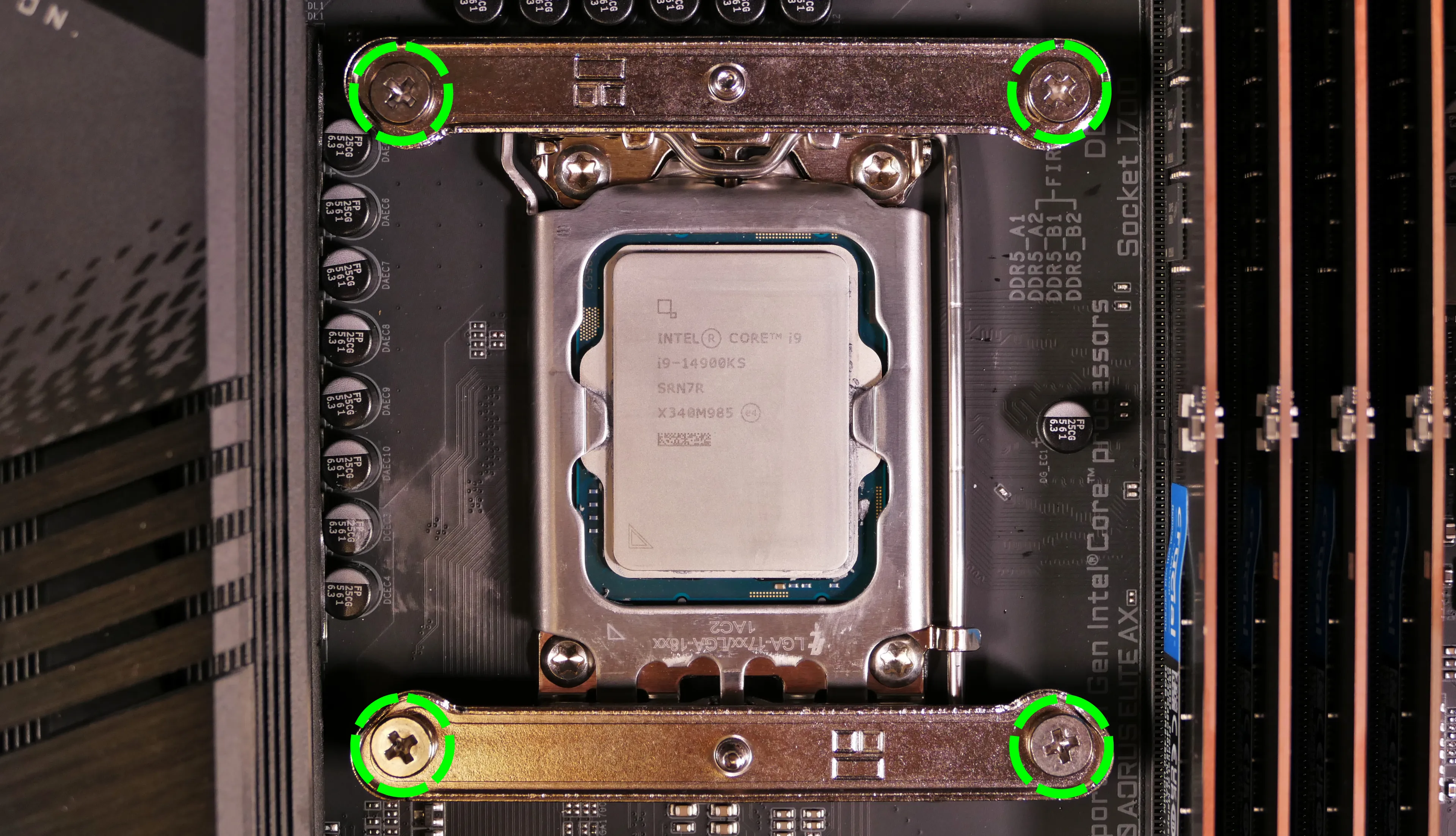
- Push the locking lever outward until it's able to spring away from the motherboard.
- Caution: the locking lever may spring up with significant force when freed.
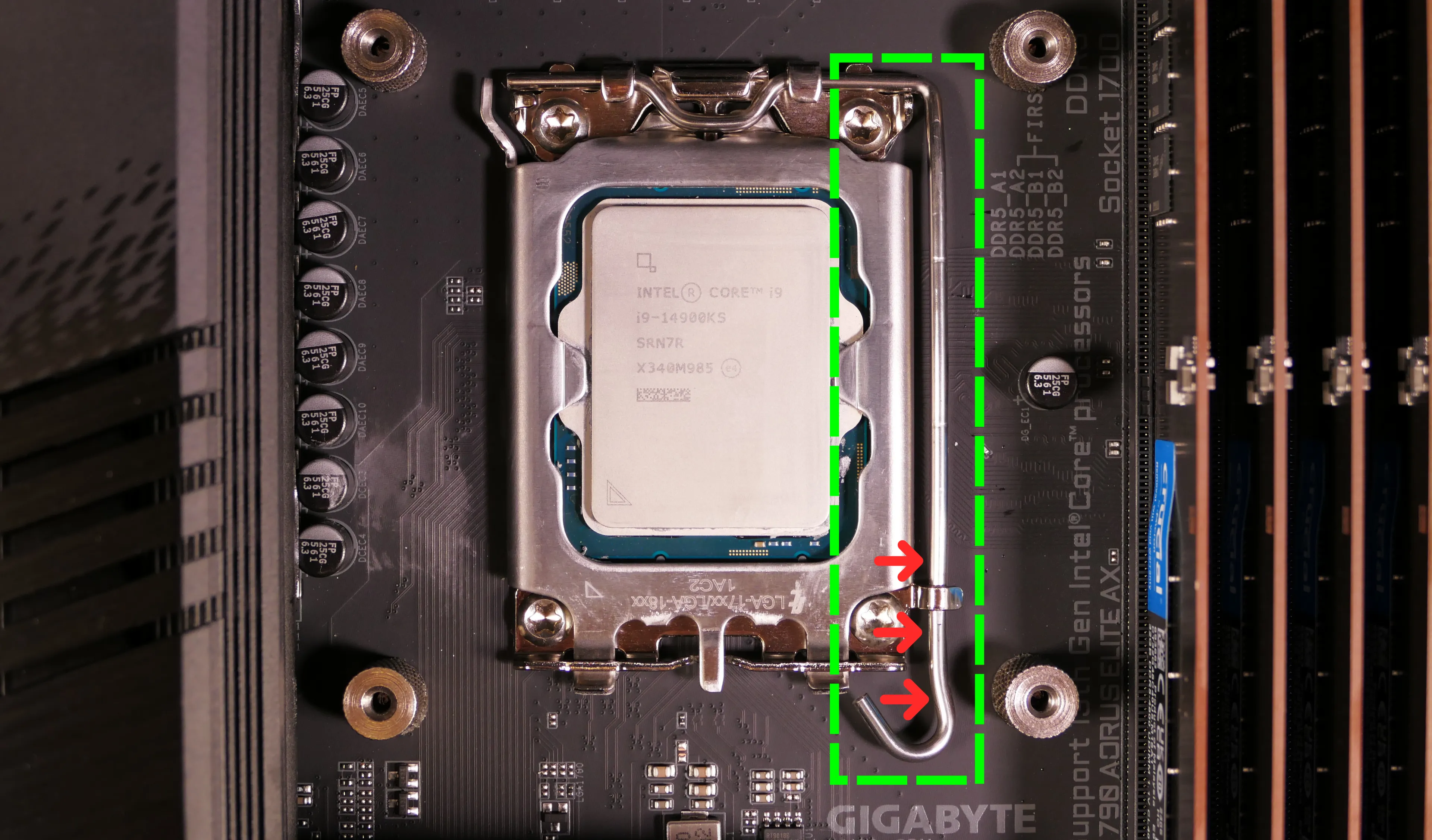
- Flip the CPU holder away from the CPU.
- The CPU holder opens in the opposite direction from the locking lever.

- Carefully lift the CPU out of the CPU socket.
- Be careful not to bend any of the gold pins on the CPU socket, and do not touch the gold pads on the CPU.

- Gently place the new CPU into the socket.
- The triangle on the CPU should be oriented to match the triangle on the CPU cover, pointing towards the bottom left of the motherboard.
- Flip the CPU cover back onto the CPU and push the locking lever down into place.
- Reinstall the horizontal CPU cooler mounting brackets.
Steps to install the thermal paste/CPU cooler:
- Draw an
Xshape of thermal paste onto the CPU.

- Place the CPU cooler onto the CPU; while holding it in place, screw its vertical mounting bar into the horizontal mounting brackets.
- The cooler should be oriented so the Thermalright logos are on the bottom.
- Insert each screw partially, then finish tightening both.
- Set the computer upright, then reinstall the cooler-mounted CPU fan, CPU duct, GPU, side brace, and top case.
Replacing the power supply:
The power supply unit (PSU) can be replaced with another unit of the same model.
Part numbers:
- The default PSU in units shipped after July 2024 is the XPG Core Reactor II.
- The default PSU in older units is the Be Quiet! Pure Power 12 M.
Tools required: Cross-head (Phillips) screwdriver
Time estimate: 45 minutes
Difficulty: Medium ●
Steps to replace the power supply:
- Follow the steps above to remove the top case, remove the side brace, and unplug the GPU (if installed).
- Unscrew the power supply bracket's left side from the bottom of the chassis.

- Unscrew and remove the cable management bracket on the right side of the chassis, then unscrew the power supply bracket's right side from the chassis.


- Unscrew the power supply's four screws from the back of the chassis.

- Unplug all of the modular cabling from the back of the PSU.

- Remove/replace the power supply.
- The replacement PSU should be installed with the fan facing the bottom of the case.
- Place the PSU on the rubber post and hold it against the screwholes in the back of the case while attaching it.
- Connect the power cables to the new power supply and GPU (if installed), then reinstall the PSU brace, side brace, and top case.
Replacing the Thelio Io board:
Named after Jupiter's moon Io, the Thelio Io daughterboard handles the front power button and fan control. If the Thelio Io board becomes defective, it can be replaced using the instructions below.
Part numbers:
- Thelio Mira B4-N3 uses Thelio Io version 2 (PCB revision thelio_io_2.3).
Tools required: Cross-head (Phillips) screwdriver
Time estimate: 30 minutes
Difficulty: High ●
Steps to replace the Thelio Io board:
- Follow the steps above to remove the top case.
- The CPU duct and side brace can optionally be removed to provide easier access to the cabling.
- Use the cutout on the front of the chassis to unplug all cabling from the Thelio Io board.
- The topmost connector requires pulling the white tab while unplugging.

- Unscrew the two screws holding the daughterboard on from the right side of the chassis.

- Screw in the new Thelio Io board and reconnect the wiring.
Thelio Io wiring guide:

-
When wiring the Thelio Io board, refer to the port labels and the following guide.
FANOUT1/CPU FAN- to the top fan splitter (connecting to the CPU fans).FANOUT4/AUX FAN- to the bottom fan splitter (below the CPU fan splitter).FANOUT2/INTAKE FAN- to the bottom case fan.FANOUT3/GPU FAN- to the side brace fan splitter.- May be disconnected by default if no side fan is ordered as factory configuration.
FANIN1/MOTHERBOARD FAN INPUT- to theCPU_FANheader at the top right of the motherboard, highlighted cyan below.

POWER1/POWER INPUT- to the power supply.- The white plastic clip needs to be held away from the connector to unplug this cable from the Thelio Io board.
PFP1/FRONT PANEL- to the power button receptacle on the front panel.- On the Thelio Io board, the wire color order (from top to bottom) is red, black, blue, black.
- On the power button receptacle, the wire color order (from left to right) is red, black, blue, black.
PMB1/MOTHERBOARD- to the first four pins of theF_PANELheader at the bottom right of the motherboard, highlighted green below.- On the Thelio Io board, the wire color order (from top to bottom) is red, black, blue, black.
- On the motherboard, the wire color order (from left to right) is red, black, blue, black.
USB- to theUSB_3_4header on the bottom edge of the motherboard, highlighted yellow below.- A small clip needs to be held down to unplug this cable from the Thelio Io board.
- This port can alternatively be connected to the
USB_5_6header if theUSB_3_4header is connected to the wireless card.

Replacing the SATA backplane:
The SATA backplane provides two 2.5" SATA data and power connectors for the 2.5" drive cage.
Part numbers:
- The part number and version for the SATA backplane is thelio-io-sata_2.2.
Tools required: Cross-head (Phillips) screwdriver
Time estimate: 30 minutes
Difficulty: Medium ●
Steps to replace the SATA backplane:
- Follow the steps above to remove the top case, then remove the 2.5" drive cage cover and all 2.5" SATA drives.
- The CPU duct can optionally be removed to provide easier access to the cabling.
- Use the cutouts on the front right corner of the chassis to unplug the 4-pin Berg power connector (highlighted cyan below) and the two SATA data cables (highlighted green below) from the SATA backplane.

- Unscrew the four screws holding the drive cage onto the chassis (highlighted red above), then remove the drive cage from the chassis.
- Unscrew the four SATA backplane screws from the drive cage, then push the SATA backplane out through the front of the drive cage.

- Place the new SATA backplane into the drive cage and secure it with the four SATA backplane screws, then reinstall the drive cage (if necessary).
- Plug the 4-pin Berg power connector and SATA data cables into the SATA backplane.
- The order of the SATA data cables shouldn't matter as long as your operating system and software is configured to address disks by UUID (e.g.
/dev/disk/by-id/...) instead of by letter (e.g./dev/sd_). - By default, the
DATA1port connects to SATA port 4 on the motherboard, and theDATA0port connects to SATA port 5. - Ensure the cables are not plugged into SATA ports 2 and 3 (the bottom two ports), as these ports are unavailbable when the bottom M.2 slot contains a PCIe NVMe SSD.
- The order of the SATA data cables shouldn't matter as long as your operating system and software is configured to address disks by UUID (e.g.

- Reinstall the CPU shroud (if necessary), any 2.5" drives that were removed, the 2.5" drive cage cover, and the top case.
Replacing the top I/O:
Thelio Mira B4-N3 includes a top I/O module providing audio and USB ports. If the top ports are damanged or become defective, they can be replaced using the steps below.
Part numbers:
- The top I/O module's part number is
MYS7523 Rev. 4.0.
Tools required: Cross-head (Phillips) screwdriver
Time estimate: 30 minutes
Difficulty: Medium ●
Steps to replace the top I/O:
- Follow the steps above to remove the top case and remove the CPU duct.
- You can optionally remove the side brace for easier access to the wiring.
- Unplug the
F_AUDIOheader at the bottom-left corner of the motherboard, below the wireless card.

- Unplug the
F_U32header (highlighted cyan below) andF_U32Cheader (highlighted green below) along the right edge of the motherboard, between the RAM and the 2.5" drive cage.

- Unscrew the two front screws holding the top I/O board onto the chassis.

- Remove the top I/O board from the system.
- Insert the new top I/O board into the system and screw it into place.
- Reconnect the audio and USB headers.
- Replace the side brace (if necessary), CPU shroud, and top case.
Troubleshooting the power button:
If the front power button doesn't power the machine on or doesn't light up when the system is powered on, try the following troubleshooting steps:
- Ensure the system powers on normally using the internal power button.
- Reseat the front power button to ensure it's making proper contact.
- Check the wiring for the front power button.
- Replace the front power button, if necessary.
Tools required: Cross-head (Phillips) screwdriver (optional)
Time estimate: 20 minutes
Difficulty: Medium ●
Steps to power the machine on using the internal power button:
- Follow the steps above to remove the top case.
- Ensure the system is plugged into power, and the power supply switch is in the 1 (On) position.
- Push the small button labeled
POWERon the Thelio Io board.- The white LED to the left of the button lights up to indicate when the system is powered on (and pulses when the system is suspended).

- If the Thelio Io
POWERbutton powers the machine on and the LED lights up, then the issue is either the front power button or its connection to the Thelio Io board. Check the front power button wiring. - If the Thelio Io
POWERbutton and/or LED does not work, then the issue is either the Thelio Io board or its connection to the motherboard. Check the wiring between the Thelio Io board and the motherboard.
Steps to check the front power button wiring:
- Follow the steps above to remove the top case.
- In the below photo, the 2.5" drive cage has also been removed for greater visibility.
- On the back of the power button, the four pins should be connected to the four-wire connector as follows:

- On the front power button receptacle, the four-pin connector should have the red wire on the left and the black wire on the right (when viewed from the back of the computer.)
- If necessary, you can remove the 2.5" drive cage for easier access to the power button receptacle's connector.

- The front power button receptacle should plug into the
PFP1port on the Thelio Io board, with the red wire on the top (see the Thelio Io wiring guide.)
Steps to replace the power button:
- Follow the steps above to remove the top case.
- Follow the instructions in the Replace the Thelio Power Button support article.
Thelio Mira (thelio-mira-r3)
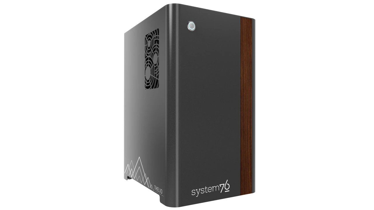
The System76 Thelio Mira is a desktop with the following specifications:
- Processor options
- Supports AMD Ryzen 7000 series (Zen 4) CPUs
- Motherboard
- Gigabyte X670 Aorus Elite AX running System76 Firmware (non-open)
- AMD X670 chipset
- Daughterboard
- Thelio Io board running open-source firmware
- Graphics options
- Up to two dedicated GPUs
- Primary GPU slot:
- PCIe 4.0 x16
- Up to 4-slot height
- Secondary GPU slot:
- PCIe 4.0 x4
- Fits physical x16 cards, runs at x4 bandwidth
- Up to 2-slot height
- PCIe 4.0 x4
- Primary GPU slot:
- GPU size:
- Internal clearance: 318.80mm
- Recommended maximum length: 308.80mm
- Tested with the following GPUs:
- Integrated Graphics
- 1x HDMI 2.1
- NVIDIA GeForce GT 1030
- 1x HDMI 2.0b, 1x DisplayPort 1.4, 1x DVI-D (single-link)
- AMD Radeon RX 6500 XT
- 1x HDMI 2.1, 1x DisplayPort 1.4a
- AMD Radeon RX 6600
- 1x HDMI 2.1, 3x DisplayPort 1.4a
- NVIDIA GeForce RTX 3060
- 1x HDMI 2.1, 3x DisplayPort 1.4a
- NVIDIA GeForce RTX 3060 Ti
- 1x HDMI 2.1, 3x DisplayPort 1.4a
- NVIDIA GeForce RTX 3070
- 1x HDMI 2.1, 3x DisplayPort 1.4a
- NVIDIA GeForce RTX 3070 Ti
- 1x HDMI 2.1, 3x DisplayPort 1.4a
- NVIDIA RTX A2000
- 4x Mini DisplayPort 1.4
- NVIDIA RTX A4000
- 4x DisplayPort 1.4
- NVIDIA RTX A6000
- 4x DisplayPort 1.4a
- Requires 750W+ PSU
- Integrated Graphics
- Up to two dedicated GPUs
- Expansion
- 1x PCIe 4.0 x16 (primary GPU slot)
- 1x PCIe 4.0 x4 (secondary GPU slot)
- Fits physical x16 cards, runs at x4 bandwidth
- 1x PCIe 4.0 x2
- Fits physical x16 cards, runs at x2 bandwidth
- Memory
- Up to 128GB (4x32GB) dual-channel DDR5 DIMMs @ 3600 MHz
- 64GB (2x32GB) and less runs at 4800 MHz
- Tested with the following RAM modules (may ship with other tested modules):
- Crucial CT8G48C40U5 (8GB/stick)
- Kingston Fury KF556C40BB-8 (8GB/stick)
- Crucial CT16G48C40U5 (16GB/stick)
- Kingston Fury KF556C40BB-16 (16GB/stick)
- Crucial CT32G48C40U5 (32GB/stick)
- Kingston Fury KF556C40BB-32 (32GB/stick)
- Up to 128GB (4x32GB) dual-channel DDR5 DIMMs @ 3600 MHz
- Networking
- 1x 2.5-Gigabit Ethernet (Realtek RTL8125)
- Wi-Fi 6E + Bluetooth 5.2 (AMD/MediaTek RZ616)
- Power
- C13 power cord
- 650W minimum PSU
- Some GPU configurations require 750W PSU
- Tested with the following PSU models (may ship with other tested models):
- Sound
- 3.5mm line out, line in, microphone jacks
- Up to 7.1-channel audio output
- Realtek ALC897 audio chipset
- HDMI, DisplayPort audio (depending on GPU)
- Storage
- 1x M.2 (PCIe NVMe Gen 5) SSD
- 3x M.2 (PCIe NVMe Gen 4) SSDs
- 4x 2.5" SATA III
- USB
- 1x USB 3.2 Gen 2x2 Type-C
- Does not support Thunderbolt or DisplayPort over USB-C.
- 2x USB 3.2 Gen 2 Type-A
- 6x USB 3.2 Gen 1 Type-A
- 4x USB 2.0 Type-A
- 1x USB 3.2 Gen 2x2 Type-C
- Dimensions
- 43.635cm × 25.3cm × 33.1cm
Thelio Mira (External Overview)
Back overview:

Power Switch Guide:
- 1: On
- 0: Off
Other Notes:
- The
ECO(ECO Mode) switch on the power supply should always be set toONfor an optimal fan curve. - The
BIOS(BIOS Flash) button is not needed when performing UEFI firmware updates via the System76 Firmware Manager. Use of the BIOS Flash button is not recommended.
Front/side overview:

Top/bottom overview:

Thelio Mira (Internal Overview)
Left side overview:

- CPU cooler & CPU are highlighted in red (located behind the CPU duct)
- RAM slots are highlighted in green
- 2.5" SATA drive cage is highlighted in pink
- M.2 slots are highlighted in white (located underneath the GPU & heatsinks)
- GPU (in PCIe 4.0 x16 slot) is highlighted in yellow
- PCIe 4.0 x4 and x2 slots are highlighted in dark blue
- Power supply is highlighted in cyan
- Bottom case fan is highlighted in orange
Right side overview:

- Thelio-IO access cutout is highlighted in green
- Power supply access cutout is highlighted in red
Front side overview:

- Thelio-IO connector access cutout is highlighted in green
Top overview:

- 2.5" drive screws are highlighted in green
- CPU power connector is highlighted in red
- Connects to power supply
- Motherboard CPU fan header is highlighted in yellow
- Connects to Thelio-IO board
- Power button receptacle is highlighted in cyan
- Connects to Thelio-IO board
See the repairs page for detailed information about installing or replacing components.
Thelio Mira (Parts & Repairs)
Many components in your Thelio Mira can be upgraded or replaced as necessary. This page uses photos of the initial revision for this generation (R3-0). Minor case details may vary on newer units, but screw counts, general component locations, and other details should remain the same unless otherwise noted.
Power the machine off, switch off the power supply, and unplug all peripherals before working with any internal components. Then, follow these step-by-step guides for instructions:
- Replacing the front accent strip
- Removing the top case
- Adding/removing 2.5" storage drives
- Replacing the bottom case fan
- Replacing the GPU
- Removing the CPU duct
- Replacing the RAM
- Replacing the M.2 drives
- Replacing the CPU fans
- Replacing the CPU cooler/thermal paste and CPU
- Replacing the power supply
- Replacing the Thelio-IO board
- Troubleshooting the power button
Replacing the front accent strip:
Thelio Mira includes a customizable accent panel on the front of the case, which can be swapped to change the case's look and feel. The instructions for swapping the accent are also available in video form.
Tools required: None
Time estimate: 30 seconds
Difficulty: Easy ●
Steps to replace the front accent strip:
- Place the Thelio on the edge of the desk so the front side is hanging off of the desk.
- The Thelio can alternatively be lifted or tilted so the front of the computer is hovering above the desk.
- Slide the accent strip down to unlock it.
- The accent can be gripped at the bottom edge.
- Pull the accent strip off of the case, starting with the bottom edge.
- Place the new accent strip onto the front of the case and slide it up to lock it into place.

Removing the top case:
The top case can be removed to access the internal components.
Tools required: Cross-head (Phillips) screwdriver (optional)
Time estimate: 2 minutes
Difficulty: Easy ●
Steps to remove the top case:
- Remove the eight outer screws holding the top case onto the machine.

- Slide the top case up and off of the machine.
Adding/removing 2.5" storage drives:
Thelio Mira R3 supports up to four 2.5" SATA III drives.
Tools required: Cross-head (Phillips) screwdriver (optional)
Time estimate: 7 minutes
Difficulty: Easy ●
Steps to add/remove 2.5" storage drives:
- Follow the steps above to remove the top case.
- Unscrew the two screws securing the drive bay's cover, highlighted green below.

- If you are adding a new drive, pop out the black plastic ring on the top crossbar and slide out four screws (per drive).

- Insert four screws into each 2.5" storage drive you wish to install.
- Slide each 2.5" drive into one of the slots leading to the Thelio-IO board.


Thelio Mira R3 with one 2.5" drive installed.
- Replace the black plastic screw ring and the 2.5" drive bay cover.
Replacing the bottom case fan:
Thelio Mira R3 has one case-mounted intake fan on the bottom of the chassis.
Tools required: Cross-head (Phillips) screwdriver
Time estimate: 20 minutes
Difficulty: Medium ●
Steps to replace the bottom case fan:
- Follow the steps above to remove the top case.
- Unplug the fan's cable from the Thelio-IO daughterboard.
- The bottom case fan plugs into the
INTAKE0port on the Thelio-IO board. - When viewed from the front of the case, this connector is second from the top.
- The bottom case fan plugs into the

- Unscrew the four fan screws from the bottom of the machine.
- To avoid damaging other components, place the machine on its front side when working with the bottom surface.

- Remove the old fan from the case.
- When installing the fan, mount the components in the following order:
- Chassis
- Dust filter
- Acrylic spacer
- Fan
- The new fan's cable should be oriented towards the front-right corner of the case.
- The cable runs along the inner corner of the case, and does not pass through any of the cable management holes or velcro strips.
Replacing the GPU:
Thelio Mira supports two multi-slot dedicated GPUs:
- The top GPU slot is a PCIe 4.0 x16 slot.
- There are four units of clearance in the back of the chassis.
- The bottom GPU slot is a PCIe 4.0 x4 slot.
- There are two units of clearance in the back of the chassis.
- This slot is forwards-compatible with x16 cards.
Factory configurations only include one GPU.
Tools required: Cross-head (Phillips) screwdriver
Time estimate: 15 minutes
Difficulty: Medium ●
Steps to replace the GPU:
- Follow the steps above to remove the top case.
- Unscrew the two back screws holding the PCIe bracket in place, and remove the PCIe bracket.

- Unscrew the four screws holding the side GPU brace in place. Remove the brace.

- If you're removing a GPU, unplug the GPU power cable from the right side of the card. Hold down the latch on the connector while unplugging the cable.

- Push and hold the latch on the motherboard to free the PCIe connection, then pull the card out of the slot.

- After inserting the new GPU into its slot, connect the power cable.
- Once the GPU is installed, replace the side GPU brace, back PCIe bracket, and top case.
- The side GPU brace includes screws to adjust for the height and depth of the graphics cards.

The GPU brace's primary function is to prevent damage during shipping. The system can be run without the brace if it doesn't fit an upgraded card; the back PCIe bracket provides primary support for the GPU.
Removing the CPU duct:
The CPU duct guides airflow through the CPU cooler. It covers the CPU and partially obstructs the RAM slots and top GPU.
Tools required: Cross-head (Phillips) screwdriver
Time estimate: 7 minutes
Difficulty: Easy ●
Steps to remove the CPU duct:
- Follow the steps above to remove the top case and remove the GPU brace.
- The GPU can also optionally be removed to provide more room for working with the components.
- Unplug the connectors for the CPU fans from the splitter board on the top crossbar.
- The splitter board provides the same signal to both ports, so it doesn't matter which fan is plugged into which port.

- Unscrew the four back screws holding the CPU duct in place.

- Pull the CPU duct away from the machine.
Replacing the RAM:
Thelio Mira R3 supports up to 128GB (4x32GB) of RAM. The RAM sticks are DDR5 DIMMs (non-ECC) running at a speed of up to 4800MHz (the maximum 4x32GB configuration is limited to 3600MHz). If you've purchased new RAM, need to replace your RAM, or are reseating your RAM, follow these steps.
Tools required: Cross-head (Phillips) screwdriver
Time estimate: 15 minutes
Difficulty: Medium ●
Steps to replace the RAM:
- Follow the steps above to remove the top case and remove the CPU duct.
- Removing the CPU duct is optional, but is recommended to provide easier access to the leftmost RAM slot.
- To remove an existing RAM stick, flip the top and bottom latches away from the stick, then pull the stick out of the slot.

- Make sure the tabs on the top and bottom of the slot are open (pulled away from the slot), then insert the new RAM (or re-seat the existing RAM) into the slot.
- The RAM stick will only fit in one direction. The larger group of pins goes on top.
- Use the following guide for placement of the RAM sticks:

- Replace the top case.
Replacing the M.2 drives:
Thelio Mira R3 has four M.2 storage slots. All four slots are M key and size 2280.
- Slot 1 supports PCIe NVMe Gen 5.
- Slots 2, 3, and 4 support PCIe NVMe Gen 4.
Tools required: Cross-head (Phillips) screwdriver
Time estimate: 30 minutes
Difficulty: Medium ●
Steps to replace the M.2 drive:
- Follow the steps above to remove the top case.
- Unscrew and remove the M.2 heatsink.
- Slot 1 is located underneath the single-height heatsink; slots 2, 3, and 4 are located underneath the triple-height heatsink.
- The heatsink screws are held captive, and will not fully come out of the heatsink.
- It may take some pressure to remove the heatsink and thermal tape from the M.2 drive. After unscrewing the heatsink, pull slowly to avoid breaking the thermal tape.

- For the M.2 drive(s) being removed, push the rectangular side of the retaining clip to flip it open.

- Remove the existing M.2 drive by pulling it out of the slot.
- Insert the new M.2 drive into the slot and hold it in place.
- Flip the retaining clip back into place and push the circular side until it snaps closed.
- Replace the M.2 heatsink, CPU duct, GPU, GPU brace, and top case.
- If you are populating an SSD slot for the first time, remove any protective plastic that may be covering the thermal tape.
- When installing the Slot 1 heatsink, fit the tab on the opposite end from the screw into the motherboard standoff before lining up the screw.

Replacing the CPU fans:
Thelio Mira R3 contains two CPU fans. One is mounted on the CPU duct, and one is mounted on the CPU cooler.
Tools required: Cross-head (Phillips) screwdriver
Time estimate: 25 minutes
Difficulty: Medium ●
Steps to replace the duct-mounted CPU fan:
- Follow the steps above to remove the top case, remove the GPU brace, and remove the CPU duct.
- Free the fan cable from the velcro loop, highlighted cyan below.
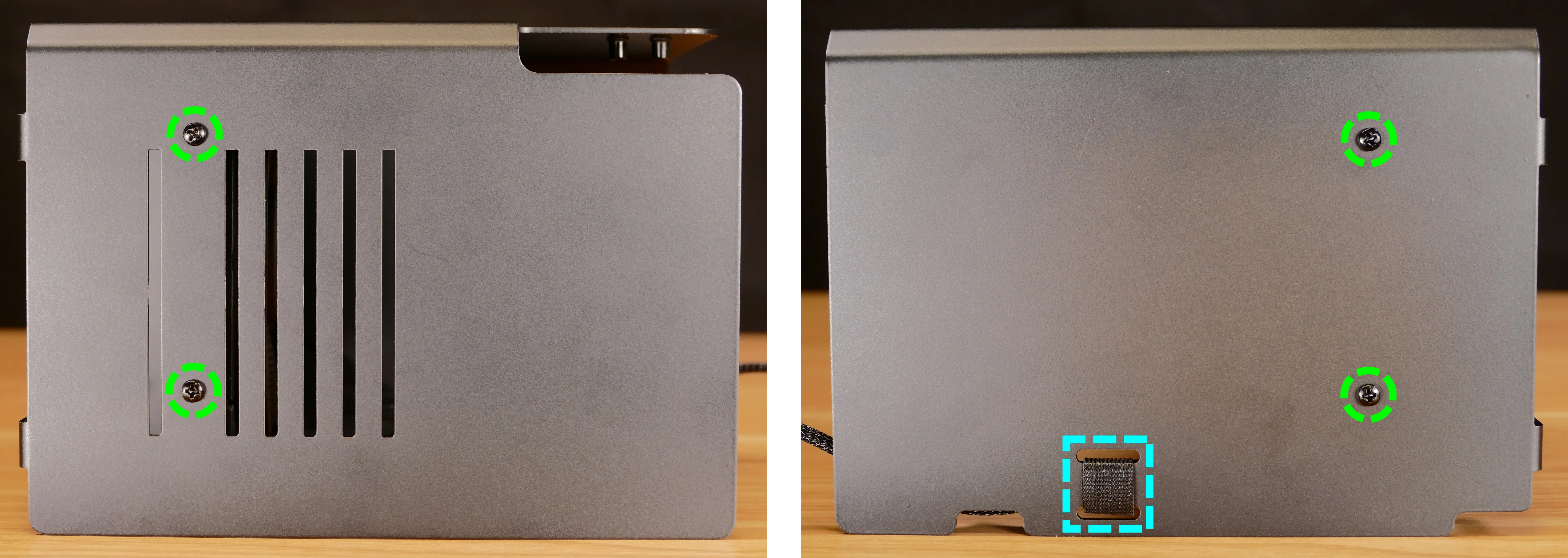
- Unscrew the four screws (two on each side) holding the fan bracket onto the duct.
- Removing the bracket from the duct is not required to remove the fan, but it makes installing the fan much easier.
- Unscrew the four screws attaching the bracket to the fan.

- When reinstalling the fan into the CPU duct, the spinning side should face inward (towards the front of the chassis), and the cable should point towards the closed corner of the top side of the duct (the top-right corner, when viewed from the back.)
- Overtightening the fan bracket's screws may cause fan noise; if the fan is creating excessive noise, try slightly loosening some of the screws.
Steps to replace the cooler-mounted CPU fan:
- Follow the steps above to remove the top case, remove the GPU brace, and remove the CPU duct.
- Pull the corners of the fan's top clip away from the heatsink it's held to.
- Alternatively, the opposite side of the bracket (clipped onto the heatsink) can be released first.

- Repeat the process for the bottom clip, then pull the fan and clips away from the CPU cooler.
- When reinstalling the CPU cooler fan, the side with a stationary cover should face the cooler, while the spinning side should face the front of the chassis.
- The cable should point towards the top inner corner (top-left when viewed from the back of the case.)
Replacing the CPU cooler and CPU:
The CPU cooler dissipates heat from the CPU to the heatsink, where the CPU fans expel it from the system. Depending on your climate and the age of the machine, replacing the thermal paste between the CPU and the cooler/heatsink may help the system run cooler.
The CPU uses an AMD AM5 socket. The CPU cooler is a Noctua NH-U12S.
Tools required: Cross-head (Phillips) screwdriver, thermal paste
Time estimate: 45 minutes
Difficulty: High ●
Steps to remove the CPU cooler/thermal paste:
- Follow the steps above to remove the top case, remove the GPU brace and GPU, remove the CPU duct, and remove the cooler-mounted CPU fan.
- While holding the CPU cooler in place so it doesn't fall, unscrew the two screws holding the CPU cooler crossbar onto the vertical mounting brackets.
- The screws are held captive, and will not fully come out of the crossbar.
- Only the two outer screws need to be removed; the center screw holding the horizontal crossbar onto the heatsink does not need to be removed.

- The cooler will come away from the CPU.
- Using a paper towel, clean the existing thermal paste off of the heatsink and CPU. You may also use a small amount of rubbing alcohol if the old paste is dried or difficult to remove.

Steps to replace the CPU:
- Place the computer on its side so the motherboard is facing up.
- Unscrew and remove the cooler mounting bracket on the right side of the CPU.

- Push the locking pin outward until it's able to spring away from the motherboard.
- Caution: the locking pin may spring up with significant force when freed.

- Flip the CPU holder away from the CPU.
- The CPU holder opens in the opposite direction from the locking pin.

- Carefully lift the CPU out of the CPU socket.
- Be careful not to bend any of the gold pins on the CPU socket, and do not touch the gold pads on the CPU.

- Gently place the new CPU into the socket.
- The triangle on the CPU should be oriented to match the triangle on the CPU cover, pointing towards the top left of the motherboard.
- Flip the CPU cover back onto the CPU and push the locking pin down into place.
- Reinstall the right-side cooler mounting bracket.
Steps to install the thermal paste/CPU cooler:
- Draw an
Xshape of thermal paste onto the CPU.

- Place the CPU cooler onto the CPU; while holding it in place, screw each end of the cooler crossbar onto one of the mounting brackets.
- The cooler should be oriented so the text is readable from the right side (front of the case).
- Insert each screw partially first, then fully tighten both.
- Set the computer upright, then reinstall the cooler-mounted CPU fan, CPU duct, GPU, GPU bracket, and top case.
Replacing the power supply:
The power supply unit (PSU) is modular and can be replaced with another unit of the same model. Different models may not be compatible with the cabling pre-installed in the Thelio.
Tools required: Cross-head (Phillips) screwdriver
Time estimate: 20 minutes
Difficulty: Medium ●
Steps to replace the power supply:
- Follow the steps above to remove the top case and remove the GPU brace and bottom GPU.
- Unplug all of the modular cabling from the back of the PSU.
- Some of the cables may be easier to unplug after the PSU has been unscrewed/removed from the case.

- Unscrew and remove the PSU bracket.
- One screw is located on the opposite side of the case.

- Unscrew the four screws holding the PSU in from the back of the case.

- Remove/replace the PSU.
- Set the replacement PSU on top of the rubber post that holds it at the correct height.
- The replacement PSU should be installed with the fan facing the bottom of the case.

- After screwing in the replacement PSU, use the labels and pin counts on the cables and ports to ensure the power cables are reconnected in the proper locations.
- Remember that not all of the available connectors will plug into the PSU-- two 8-pin (6 + 1) connectors are to be plugged into the GPUs.
- If the replacement PSU has an
ECOswitch, make sure it is switched on for an optimal fan curve.
Replacing the Thelio-IO board:
The Thelio-IO board handles the front power button, fan control, and 2.5" SATA connectors for the system. If the Thelio-IO board becomes defective, it can be replaced using the instructions below.
Tools required: Cross-head (Phillips) screwdriver
Time estimate: 25 minutes
Difficulty: High ●
Steps to replace the Thelio-IO board:
- Follow the steps above to remove the top case and remove the 2.5" drive cage cover and any 2.5" drives that are installed.
- Use the cutouts on the front right corner of the chassis to unplug all cabling from the Thelio-IO board.
- The topmost connector requires pulling the white tab while unplugging.

- Unscrew the two screws on the top side of the drive cage.

- While pulling the loose side of the drive cage away from the Thelio-IO board, move the board back and out of the drive cage.
- Place the new Thelio-IO board into the drive cage and replace the screws and wiring.
Thelio-IO wiring guide:

- When wiring the Thelio-IO board, refer to the above image and the following guide. The ports are numbered in the suggested connection order based on position and size.
- 1:
POWER0- to the power supplyPERIFport (via 4-pin Molex adapter.) - 2:
INTAKE0- to the bottom case fan. - 3:
CPUOUT0- to the splitter board (on the top crossbar) connecting to both CPU fans. - 4:
CPUIN0- to theCPU_FANheader at the top of the motherboard.
- 5:
DATA0/1/2/3- to SATA ports #0/#1/#2/#3 on the motherboard, highlighted green below.- The ports are located next to the top GPU slot.
- These connectors provide data transfer for the 2.5" drive slots.
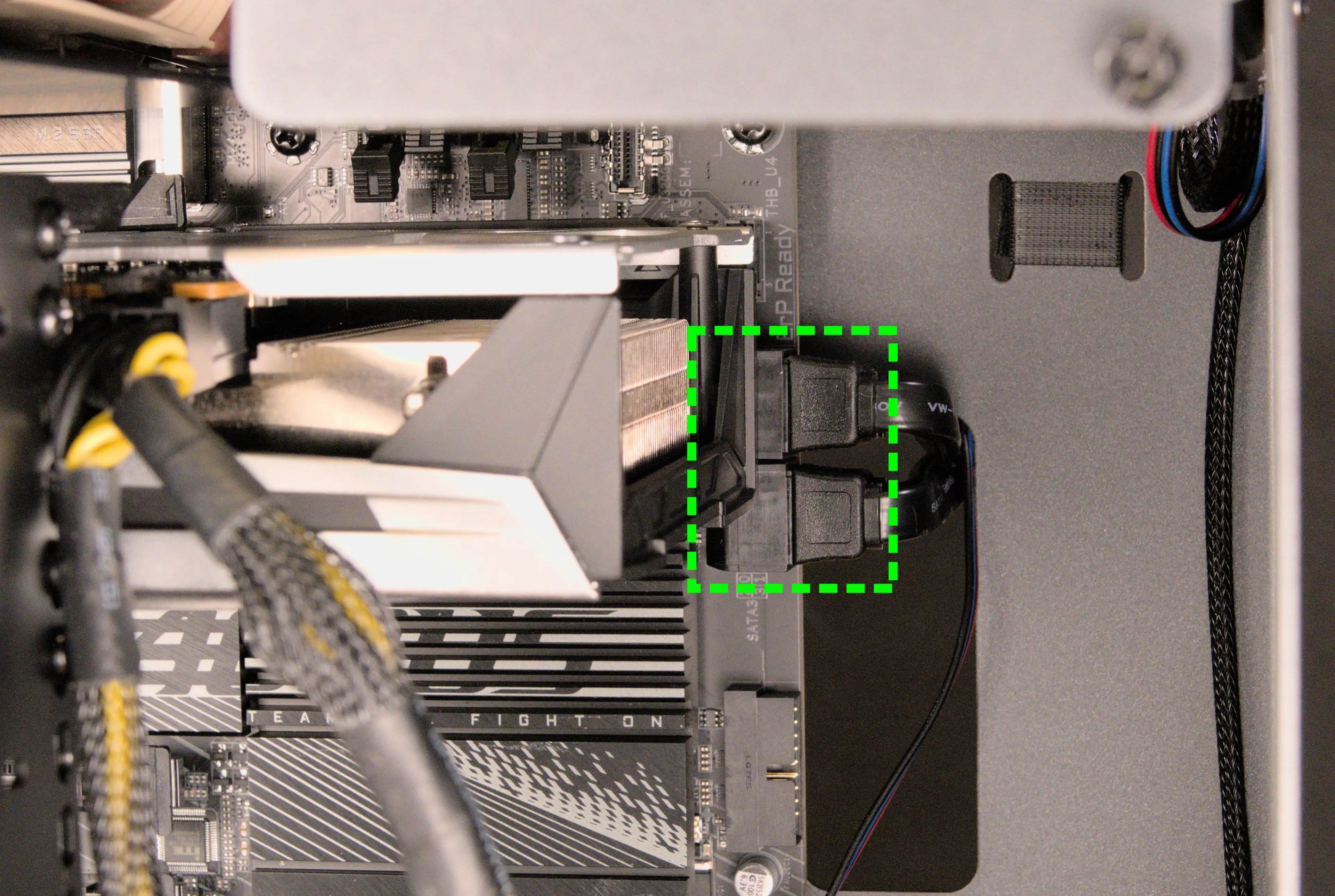
- 6*:
PFP0- to the power button receptacle on the front panel. - 7*:
USB0- to theJUSB1header on motherboard, highlighted red below.
- On the Thelio-IO board, the row of four pins plugs in, while the row of five pins hangs off the back and does not plug in.
- This connector provides fan control and firmware updates.
- 8*:
PMB0- to the+PLED-and+PW-pins (the four top-left pins of theF_PANELheader) on the motherboard.- On the motherboard, the red wire goes on the inner-left and the black wire goes on the inner-right. The corresponding black wires go on the outer-left and outer-right.
- The
F_PANELheader is at the bottom right of the motherboard.
- * For all connectors with multi-colored wires plugging into the Thelio-IO board, the red wire goes on the top side (viewing from the front of the computer.)
- 1:
Troubleshooting the power button:
If the front power button doesn't power the machine on or doesn't light up when the system is powered on, try the following troubleshooting steps:
- Ensure the system powers on normally using the internal power button.
- Reseat the front power button to ensure it's making proper contact.
- Check the wiring for the front power button.
- Replace the front power button, if necessary.
Tools required: Cross-head (Phillips) screwdriver (optional)
Time estimate: 20 minutes
Difficulty: Medium ●
Steps to power the machine on using the internal power button:
- Follow the steps above to remove the top case.
- Ensure the system is plugged into power, and the power supply switch is in the 1 (On) position.
- Push the small button labeled
B0on the Thelio-IO board.

- If the Thelio-IO
B0button powers the machine on, then the issue is either the front power button or its connection to the Thelio-IO board. Check the front power button wiring. - If the Thelio-IO
B0button does not work, then the issue is either the Thelio-IO board or its connection to the motherboard. Check the wiring between the Thelio-IO board and the motherboard.
Steps to check the front power button wiring:
- Follow the steps above to remove the top case.
- On the back of the power button, the four pins should be connected to the four-wire connector as follows:

- On the front power button receptacle, the four-pin connector should have the red wire on the left and the black wire on the right (when viewed from the back of the computer.)

- The front power button receptacle should plug into the
PFPDport on the Thelio-IO board, with the red wire on the top (see the Thelio-IO wiring guide.)
Steps to replace the power button:
- Follow the steps above to remove the top case.
- Follow the instructions in the Replace the Thelio Power Button support article.
Thelio Mira (thelio-mira-b1.0)
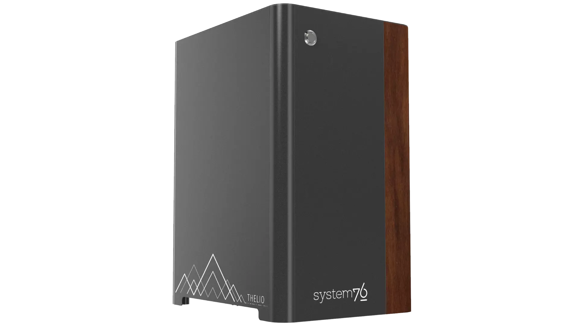
The System76 Thelio Mira is a desktop with the following specifications:
- CPU options
- Supports Intel 10th and 11th Generation (Comet Lake and Tiger Lake) CPUs
- Motherboard
- ASUS ROG STRIX Z590-A GAMING WIFI running System76 Firmware (non-open)
- Intel Z590 chipset
- Daughterboard
- Thelio Io board running open-source firmware
- GPU options
- Up to two GPUs, depending on configuration (2x PCIe 4.0/3.0 x16)
- GPU size:
- Internal clearance: 318.80mm
- Recommended maximum length: 308.80mm
- Tested with the following GPUs:
- Integrated Graphics
- HDMI 2.0 (11th Gen) or 1.4 (10th Gen), DisplayPort 1.4
- NVIDIA GeForce GTX 1650 (maximum 1)
- HDMI 2.0b, DisplayPort 1.4a, DL-DVI-D
- NVIDIA GeForce RTX 3060 (maximum 1)
- HDMI 2.1, 3x DisplayPort 1.4a
- NVIDIA GeForce RTX 3060 Ti (maximum 1)
- HDMI 2.1, 3x DisplayPort 1.4a
- NVIDIA GeForce RTX 3070 (maximum 1)
- HDMI 2.1, 3x DisplayPort 1.4a
- NVIDIA GeForce RTX 3070 Ti (maximum 1)
- HDMI 2.1, 3x DisplayPort 1.4a
- NVIDIA GeForce RTX 3080 Ti (maximum 1)
- HDMI 2.1, 3x DisplayPort 1.4a
- NVIDIA GeForce RTX 3090 (maximum 1)
- HDMI 2.1, 3x DisplayPort 1.4a
- NVIDIA Quadro RTX 4000 (maximum 2)
- 3x DisplayPort 1.4, DisplayPort over USB-C (VirtualLink)
- NVIDIA Quadro RTX 5000 (maximum 2)
- 4x DisplayPort 1.4, DisplayPort over USB-C (VirtualLink)
- NVIDIA Quadro RTX 6000 (maximum 2)
- 4x DisplayPort 1.4, DisplayPort over USB-C (VirtualLink)
- NVIDIA Quadro RTX 8000 (maximum 2)
- 4x DisplayPort 1.4, DisplayPort over USB-C (VirtualLink)
- Integrated Graphics
- Expansion
- 2x PCIe 4.0/3.0 x16 (GPU slots)
- 1x PCIe 4.0/3.0 x16 (additional slot; single-height cards only)
- 1x PCIe 3.0 x4
- Memory
- Up to 128GB (4x32GB) dual-channel DDR4 DIMMs @ 3200 MHz
- Tested with the following RAM modules (may ship with other tested modules):
- Kingston HyperX HX432C16FB3/8 (8GB/stick)
- Kingston HyperX HX432C16FB4/16 (16GB/stick)
- Kingston HyperX HX432C16FB3K4/128 (32GB/stick)
- Networking
- 1x 2.5-Gigabit Ethernet (Intel I225-V)
- Wi-Fi 6 (Intel AX200)
- Power
- C13 power cord
- 650W minimum PSU
- Dual-GPU configurations require 750W or 1000W, depending on GPU power requirements
- Tested with the following PSU models (may ship with other tested models):
- Sound
- 3.5mm line out, line in, microphone jacks
- Up to 7.1-channel audio output
- Realtek ALC4080 audio chipset (with Savitech SV3H712 amplifier)
- HDMI, DisplayPort, USB-C DisplayPort audio (depending on GPU)
- Storage
- 1x M.2 (PCIe NVMe Gen 4), M key
- Backwards compatible with PCIe NVMe Gen 3.
- Only active with 11th Gen CPUs.
- 2x M.2 (PCIe NVMe Gen 3), M key
- Backwards compatible with SATA III.
- 4x 2.5" SATA
- 1x M.2 (PCIe NVMe Gen 4), M key
- USB
- 1x USB 3.2 Gen 2x2 Type-C
- 4x USB 3.2 Gen 2 Type-A
- 1x USB 2.0 Type-C
- 4x USB 2.0 Type-A
- Dimensions
- 43.635cm × 25.3cm × 33.1cm
Thelio Mira (External Overview)
Back side overview:

Audio Port Guide:
- Top row, left to right:
- Rear Speaker Out
- Center/Subwoofer Out
- Bottom row, left to right:
- Mic in
- Line Out / Front Speaker Out
- Line In / Side Speaker Out
Power Switch Guide:
- 1: On
- 0: Off
Other Notes:
- The
ECOswitch on the power supply should always be set toONfor an optimal fan curve. - The BIOS Flash button is not needed when performing UEFI firmware updates via the System76 Firmware Manager. Use of the BIOS Flash button is not recommended.
Thelio Mira (Internal Overview)
Side overview:
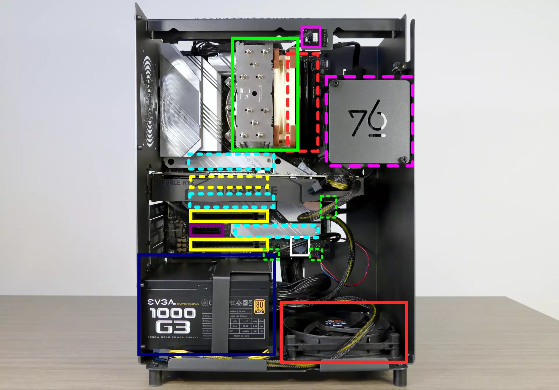
- CPU cooler & CPU cooler fan are highlighted in solid green
- CPU fan connectors are highlighted in solid pink
- RAM slots are highlighted in dashed red
- 2.5" SATA drive slot cover is highlighted in dashed pink
- M.2 slots are highlighted in dashed cyan (located underneath the heatsinks)
- PCIe x16 slots are highlighted in yellow
- Top slot (dashed yellow) is behind the GPU
- PCIe x4 slot is highlighted in purple
- Power supply is highlighted in navy
- Bottom case fan is highlighted in solid red
- Thelio-IO to motherboard connections are highlighted in dashed green
- CMOS battery is highlighted in white
PCIe slot guide:
From top to bottom:
- PCIe Gen 4 x16 slot (GPU 1)
- Runs with x8 bandwidth if slots 2 or 4 are in use.
- Runs at Gen 3 speeds with 10th Gen CPUs.
- PCIe Gen 4 x16 slot (GPU 2)
- Runs with x4 bandwidth.
- Runs at Gen 3 speeds with 10th Gen CPUs.
- PCIe Gen 3 x4 slot
- PCIe Gen 4 x16 slot
- Runs with x4 bandwidth.
- Runs at Gen 3 speeds with 10th Gen CPUs.
See the repairs page for detailed information about installing or replacing components.
Thelio Mira (Parts & Repairs)
Many components in your Thelio Mira can be upgraded or replaced as necessary. Power the machine off, switch off the power supply, and unplug all peripherals before working with any internal components. Then, follow these step-by-step guides for instructions:
- Removing the top case
- Adding/removing 2.5" storage drives
- Replacing the RAM
- Replacing the bottom case fan
- Replacing a GPU
- Removing the CPU duct
- Replacing the M.2 drives
- Replacing the CPU fans
- Replacing the CPU cooler/thermal paste and CPU
- Replacing the power supply
- Replacing the Thelio-IO board
- Troubleshooting the power button
Removing the top case:
The top case can be removed to access the internal components.
Tools required: Cross-head (Phillips) screwdriver (optional)
Time estimate: 2 minutes
Difficulty: Easy ●
Steps to remove the top case:
- Remove the eight outer screws holding the top case onto the machine.

- Slide the top case up and off of the machine.
Adding/removing 2.5" storage drives:
Thelio Mira b1.0 supports up to four 2.5" SATA III drives.
If the middle and bottom M.2 slots are used with M.2 SATA drives, the motherboard's SATA ports #2 and #6 will become disabled; however, SATA ports #2 and #6 are not used for 2.5" SATA drives in Thelio Mira. If any 2.5" drives are not being detected and M.2 SATA drives are being used, try changing the ports used for the SATA connections between the Thelio-IO board and the motherboard.
Tools required: Cross-head (Phillips) screwdriver (optional)
Time estimate: 10 minutes
Difficulty: Easy ●
Steps to add/remove 2.5" storage drives:
- Follow the steps above to remove the top case.
- Unscrew the two screws securing the drive bay's cover.
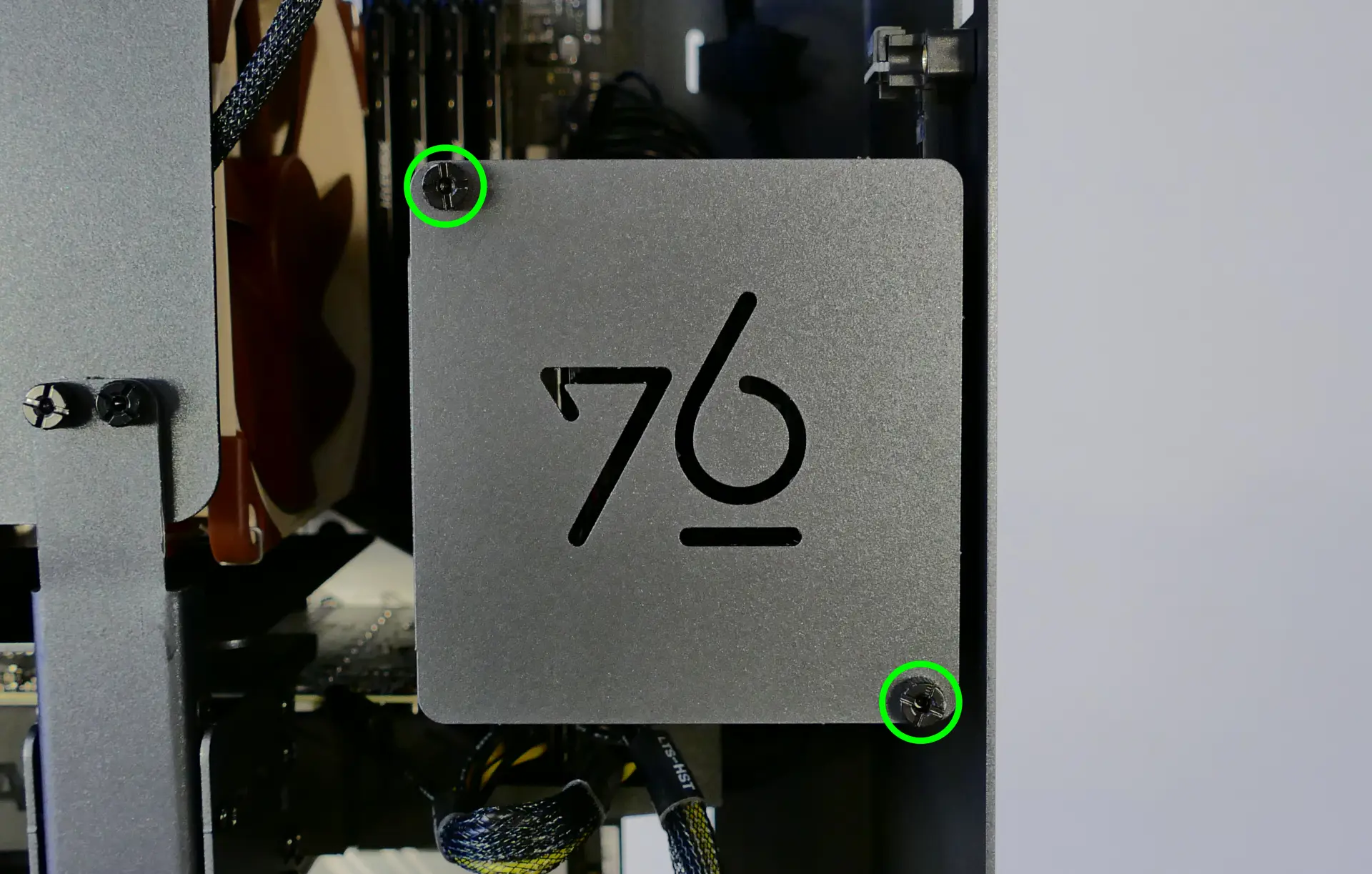
- If you are adding a new drive, pop out the black plastic ring on the top crossbar and slide out four screws (per drive).
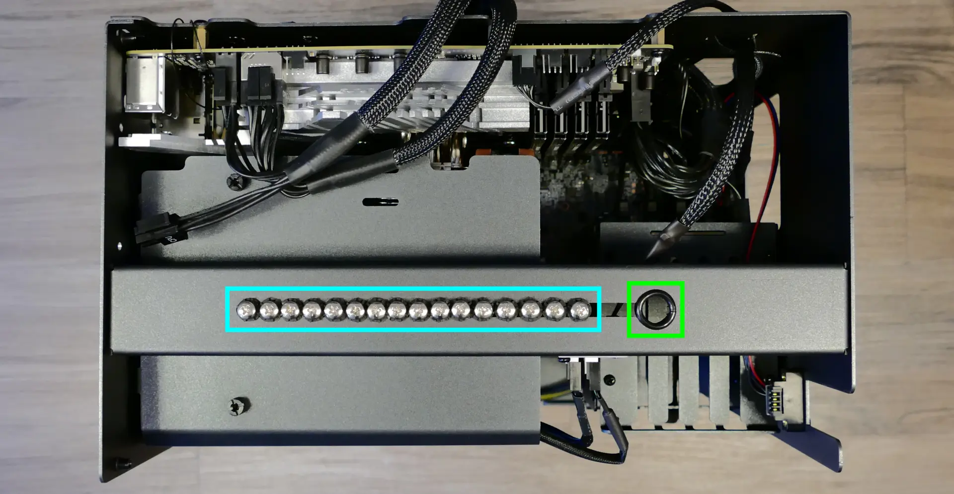
- Insert four screws into each 2.5" storage drive you wish to install.
- Slide each 2.5" drive into one of the slots leading to the Thelio-IO board.
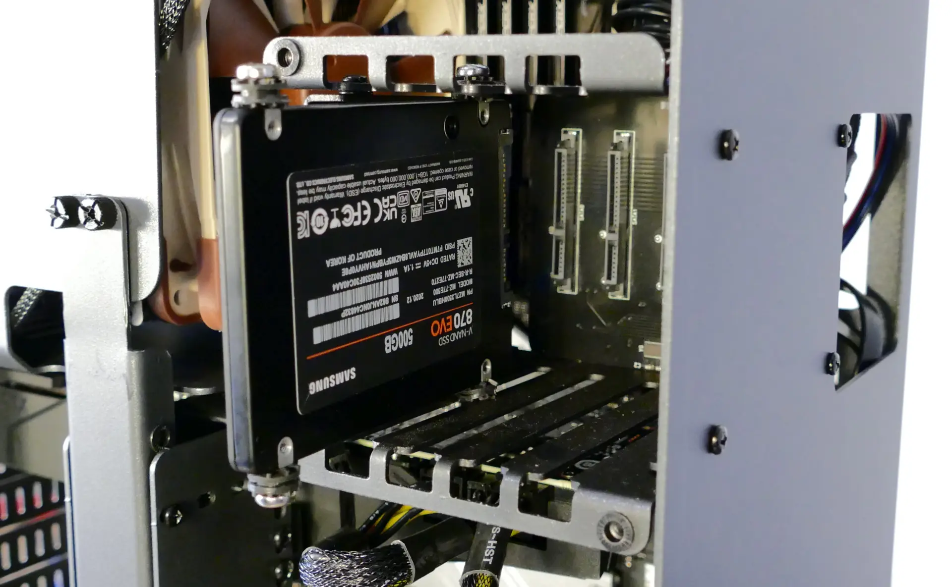
Replacing the RAM:
Thelio Mira b1.0 supports up to 128GB (4x32GB) of RAM. The RAM sticks are DDR4 DIMMs (non-ECC) running at a speed of 3200MHz. If you've purchased new RAM, need to replace your RAM, or are reseating your RAM, follow these steps.
Tools required: Cross-head (Phillips) screwdriver (optional)
Time estimate: 15 minutes
Difficulty: Medium ●
Steps to replace the RAM:
- Follow the steps above to remove the top case.
- To remove an existing RAM stick, flip the top latch up away from the stick, then pull the stick out of the slot, starting from the top edge. (The bottom of the RAM slot does not move.)

- Make sure the tab on the top of the slot is open (pulled upwards), then insert the new RAM (or re-seat the existing RAM) into the slot.
- The RAM stick will only fit in one direction. The larger group of pins goes on top.
- Use the following guide for placement of the RAM sticks:

- Replace the top case.
Replacing the bottom case fan:
Thelio Mira b1.0 has one case-mounted intake fan on the bottom of the chassis.
Tools required: Cross-head (Phillips) screwdriver
Time estimate: 20 minutes
Difficulty: Medium ●
Steps to replace the bottom case fan:
- Follow the steps above to remove the top case.
- Unplug the fan's cable from the Thelio-IO daughterboard.
- The bottom case fan plugs into the
INTAKE0port on the Thelio-IO board. - When viewed from the front of the case, this connector is second from the top.
- The bottom case fan plugs into the

- Unscrew the four fan screws from the bottom of the machine.
- To avoid damaging other components, place the machine on its front side when working with the bottom surface.

- Remove the old fan from the case.
- When installing the fan, mount the components in the following order:
- Chassis
- Dust filter
- Acrylic spacer
- Fan
- Thread the new fan's cable through the opening in the bottom-front corner of the case and through the velcro connector near the front edge.

Replacing a GPU:
Thelio Mira supports up to two dual-slot GPUs. All PCIe x16 slots run at Gen 4 speeds with 11th Gen processors, or Gen 3 speeds with 10th Gen processors. Mixing NVIDIA and AMD GPUs is not recommended.
Tools required: Cross-head (Phillips) screwdriver
Time estimate: 20 minutes
Difficulty: Medium ●
Steps to replace a GPU:
- Follow the steps above to remove the top case.
- Unscrew the two back screws holding the PCIe bracket in place, then slide the PCIe bracket open.

- Unscrew the four screws holding the side GPU brace in place. Remove the brace.

- If you're removing a GPU, unplug the GPU power cable from the right side of the card. Hold down the latch on the connector while unplugging the cable.

- Hold the latch on the motherboard to free the PCIe connection, then pull the card out of the slot.
- If removing the bottom GPU, it may be necessary to remove the top GPU first in order to reach the latch.
- If space is tight, a long object such as a screwdriver can be used to press the latch.

- When installing new GPUs, the slots should be utilized in the following order:
- Primary GPU: top slot.
- Secondary GPU: second slot from the top.
- After inserting the new GPU into its slot, connect the power cables.
- The maximum number of power cables are preinstalled in your system, but some may be tied back using velcro if the system shipped with less than two GPUs.
- Once all GPUs are installed, replace the side GPU brace, back PCIe bracket, and top case.
- The side GPU brace includes screws to adjust for the height of the graphics cards (highlighted green below) and the depth of the graphics cards (highlighted blue.)

The GPU brace's primary function is to prevent damage during shipping. The system can be run without the brace if it doesn't fit an upgraded card; the back PCIe bracket provides primary support for the GPUs.
Removing the CPU duct:
The CPU duct guides airflow through the CPU cooler. It covers the CPU and partially obstructs the RAM slots and top GPU.
Tools required: Cross-head (Phillips) screwdriver (optional)
Time estimate: 7 minutes
Difficulty: Easy ●
Steps to remove the CPU duct:
- Follow the steps above to remove the top case and remove the GPU brace.
- Unplug the connectors for the CPU fans.

- Unscrew the four back screws holding the CPU duct in place.

- Pull the CPU duct away from the machine.
Replacing the M.2 drives:
Thelio Mira has three M.2 slots. All slots support M.2 sizes 22110, 2280, 2260, and 2242. The following restrictions apply:
- Top M.2 slot:
- Only works with 11th Gen CPUs.
- Supports PCIe NVMe Gen 4 and PCIe NVMe Gen 3.
- Middle M.2 slot:
- Supports PCIe NVMe Gen 3 and SATA III.
- Bottom M.2 slot:
- Supports PCIe NVMe Gen 3 and SATA III.
Tools required: Cross-head (Phillips) screwdriver
Time estimate: 25 minutes
Difficulty: Medium ●
Steps to replace the M.2 drives:
- Follow the steps above to remove the top case and remove the GPU brace and GPUs.
- If you are accessing the top M.2 slot, remove the CPU duct.
- Remove the M.2 heatsink covering the slot you wish to access.
- The heatsink screws are held captive, and will not fully come out of the heatsink.
- It may take some pressure to remove the heatsink and thermal tape from the M.2 drive. After unscrewing the heatsink, pull slowly to avoid breaking the thermal tape.

- Free the retaining mechanism opposite the M.2 slot.
- The top M.2 slot uses a regular Phillips screw.
- The middle and bottom M.2 slots use a plastic locking mechanism.
- To free a drive, twist the plastic ring counter-clockwise until the tab points away from the M.2 slot.
- To secure a drive, twist the plastic ring clockwise until the tab points upwards.

- Remove the existing M.2 drive by pulling it out of the slot.
- If utilizing the top slot for the first time, peel the blue plastic covering off of the gray thermal tape on the motherboard.
- Insert the new M.2 drive into the slot and hold it in place.
- Replace the retainer screw or secure the plastic retaining tab.
- If utilizing any slot for the first time, peel the plastic backing off of the heatsink to expose the double-sided thermal tape for that slot.

- Replace the M.2 heatsinks, CPU duct, GPUs, GPU brace, and top case.
Replacing the CPU fans:
Thelio Mira b1.0 contains two CPU fans. One is mounted on the CPU duct, and one is mounted on the cooler.
Tools required: Cross-head (Phillips) screwdriver
Time estimate: 25 minutes
Difficulty: Medium ●
Steps to replace the duct-mounted CPU fan:
- Follow the steps above to remove the top case, remove the GPU brace, and remove the CPU duct.
- Unscrew the four screws (two on each side) holding the fan brackets onto the duct.
- Removing the brackets from the duct is not required to remove the fan, but it makes installing the fan much easier.

- Unscrew the four screws attaching the two brackets to the fan.

- When reinstalling the fan into the CPU duct, the spinning side should face the CPU cooler and the front of the case, while the side with a stationary cover should face the back of the case.
- Overtightening the fan bracket's screws may cause fan noise; if the fan is creating excessive noise, try slightly loosening some of the screws.
Steps to replace the cooler-mounted CPU fan:
- Follow the steps above to remove the top case, remove the GPU brace and GPUs, and remove the CPU duct.
- Pull the corners of the fan's top clip away from the heatsink it's held to.
- Alternatively, the opposite side of the bracket (clipped onto the heatsink) can be released first.

- Repeat the process for the bottom clip, then pull the fan and clips away from the CPU cooler.
- When reinstalling the CPU cooler fan, the side with a stationary cover should face the CPU cooler and back of the case, while the spinning side should face the front of the case.
Replacing the CPU cooler and CPU:
The CPU cooler dissipates heat from the CPU to the heatsink, where the CPU fans expel it from the system. Depending on your climate and the age of the machine, replacing the thermal paste between the CPU and the cooler/heatsink may help the system run cooler.
The CPU uses an Intel LGA 1200 socket. The CPU cooler is a Noctua NH-U12S.
Tools required: Cross-head (Phillips) screwdriver (long), torx screwdriver, thermal paste
Time estimate: 35 minutes
Difficulty: High ●
Steps to remove the CPU cooler/thermal paste:
- Follow the steps above to remove the top case, remove the GPU brace and GPUs, remove the CPU duct, and remove the cooler-mounted CPU fan.
- While holding the CPU cooler in place so it doesn't fall, unscrew the two screws holding the CPU cooler onto the vertical mounting brackets.

- The cooler will come away from the CPU.
- Using a paper towel, clean the existing thermal paste off of the heatsink and CPU. You may also use a small amount of rubbing alcohol if the old paste is dried or difficult to remove.

Steps to replace the CPU:
- Place the computer on its side so the motherboard is facing up.
- Push the locking pin outward until it's able to spring away from the motherboard.
- Caution: the locking pin may spring up with significant force when freed.

- Flip the CPU holder away from the CPU.

- Carefully lift the CPU out of the CPU socket.
- Be careful not to bend any of the gold pins on the CPU socket, and do not touch the gold pads on the CPU.

- Gently place the new CPU into the socket.
- When reinstalling the CPU, be sure to match the original orientation, with the triangle on the CPU pointing to the bottom left of the motherboard.
- The triangle on the CPU should match the triangle on the top of the CPU cover and the dot on the motherboard.
- Flip the CPU cover back onto the CPU and push the locking pin down into place.
Steps to install the thermal paste/CPU cooler:
- Place a line of thermal paste onto the CPU.

- Place the CPU cooler onto the CPU; while holding it in place, screw each end of the cooler crossbar onto one of the mounting brackets.
- Insert each screw partially first, then fully tighten both.
- Reinstall the cooler-mounted CPU fan, CPU duct, GPU bracket, and top case.
Replacing the power supply:
The power supply unit (PSU) is modular and can be replaced with another unit of the same model. Different models may not be compatible with the cabling pre-installed in the Thelio Mira.
Tools required: Cross-head (Phillips) screwdriver
Time estimate: 20 minutes
Difficulty: Medium ●
Steps to replace the power supply:
- Follow the steps above to remove the top case and remove the GPU brace and bottom GPU.
- Unplug all of the modular cabling from the back of the PSU.
- Some of the cables may be easier to unplug after the PSU has been unscrewed/removed from the case.

- Unscrew and remove the PSU bracket.
- One screw is located on the opposite side of the case.

- Unscrew the four screws holding the PSU in from the back of the case.

- Remove/replace the PSU. Set the replacement PSU on top of the rubber post that holds it at the correct height.
- The replacement PSU should be installed with the fan facing the bottom of the case.

- After screwing in the replacement PSU, use the labels and pin counts on the cables and ports to ensure the power cables are reconnected in the proper locations.
- Remember that not all of the available connectors will plug into the PSU-- four connectors (on two cables) are to be plugged into the GPUs.
- If the replacement PSU has an "ECO Mode" switch, make sure it is switched on for an optimal fan curve.
Replacing the Thelio-IO board:
Tools required: Cross-head (Phillips) screwdriver
Time estimate: 25 minutes
Difficulty: High ●
The Thelio-IO board handles the front power button, fan control, and 2.5" SATA connectors for the system. If the Thelio-IO board becomes defective, it can be replaced using the instructions below.
Steps to replace the Thelio-IO board:
- Follow the steps above to remove the top case and remove the 2.5" drive cage cover and any 2.5" drives that are installed.
- Use the cutouts on the front right corner of the chassis to unplug all cabling from the Thelio-IO board.

- Unscrew the two screws on the top of the upper drive cage closest to the Thelio-IO board.

- While pulling the loose side of the drive cage away from the Thelio-IO board, move the board back and out of the drive cage.
- Place the new Thelio-IO board into the drive cage and replace the screws and wiring.
Thelio-IO wiring guide:

- When wiring the Thelio-IO board, refer to the above image and the following guide.
- 1:
POWER0- to power supply (via 4-pin Molex adapter.) - 2:
INTAKE0- to bottom case fan. - 3:
CPUOUT0- to CPU fan splitter board on top crossbar. - 4:
CPUIN0- toCPU_FANheader on motherboard.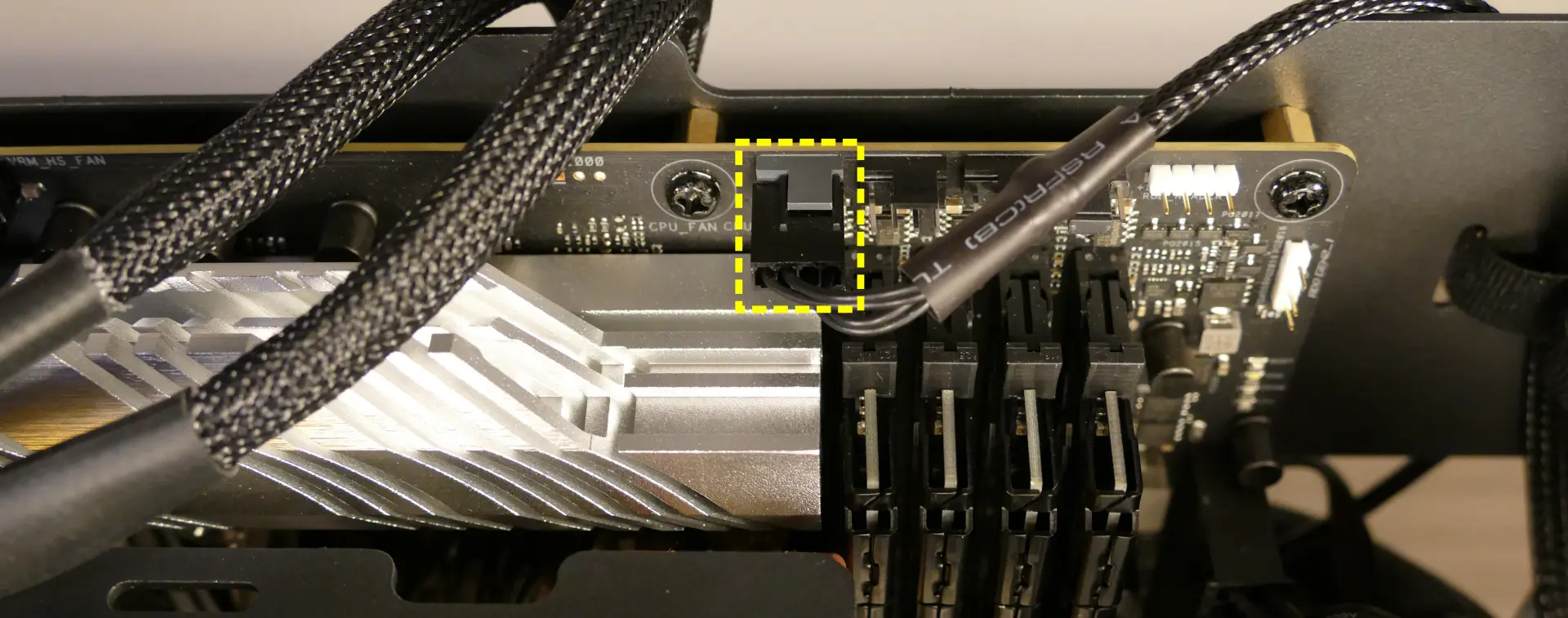
- 5:
SATA0/1/2/3- to SATA ports #1/#3/#4/#5 on motherboard. (These connectors provide data transfer for the 2.5" drive slots.)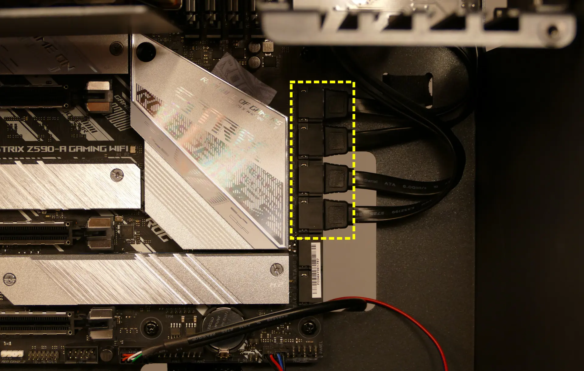
- 6*:
PFP0- to power button receptacle on front panel. - 7*:
USB0- to USB header on motherboard. (This connector provides fan control and firmware updates.)
- 8*:
PMB0- toPWR_LED-andPWR_SWheaders on motherboard.
- * For all connectors with multi-colored wires plugging into the Thelio-IO board, the red wire goes on top.
- 1:
Troubleshooting the power button:
If the front power button doesn't power the machine on or doesn't light up when the system is powered on, try the following troubleshooting steps:
- Ensure the system powers on normally using the internal power button.
- Reseat the front power button to ensure it's making proper contact.
- Check the wiring for the front power button.
- Replace the front power button, if necessary.
Tools required: Cross-head (Phillips) screwdriver (optional)
Time estimate: 20 minutes
Difficulty: Medium ●
Steps to power the machine on using the internal power button:
- Follow the steps above to remove the top case.
- Ensure the system is plugged into power, and the power supply switch is in the 1 (On) position.
- Push the small button labeled
B0on the Thelio-IO board.

- If the Thelio-IO
B0button powers the machine on, then the issue is either the front power button or its connection to the Thelio-IO board. Check the front power button wiring. - If the Thelio-IO
B0button does not work, then the issue is either the Thelio-IO board or its connection to the motherboard. Check the wiring between the Thelio-IO board and the motherboard.
Steps to check the front power button wiring:
- Follow the steps above to remove the top case.
- On the back of the power button, the four pins should be connected to the four-wire connector as follows:

- On the front power button receptacle, the four-pin connector should have the red wire on the left and the black wire on the right.

- The front power button receptacle should plug into the
PFPDport on the Thelio-IO board, with the red wire on the top (see the Thelio-IO wiring guide.)
Steps to replace the power button:
- Follow the steps above to remove the top case.
- Follow the instructions in the Replace the Thelio Power Button support article.
Thelio Mira (thelio-mira-r1.0)
The System76 Thelio Mira is a desktop with the following specifications:
- CPU options
- Supports AMD 1st through 4th gen Ryzen AM4 socket processors
- Tested with the following processors:
- Motherboard
- ASUS ROG Strix X570-E Gaming running System76 Firmware (non-open)
- AMD X570 chipset
- Daughterboard
- Thelio Io board running open-source firmware
- GPU options
- One or two GPUs, depending on configuration and power requirements (3x PCIe 4.0 x16 slots)
- GPU size:
- Internal clearance: 318.80mm
- Recommended maximum length: 308.80mm
- Tested with the following GPUs:
- NVIDIA GeForce GT 1030
- 1x HDMI 2.0b, 1x DVI-D (single link)
- NVIDIA GeForce 2080 Super
- 1x HDMI 2.0b, 3x DisplayPort 1.4, 1x DisplayPort over USB-C (VirtualLink)
- NVIDIA GeForce RTX 3060 Ti
- 1x HDMI 2.1, 3x DisplayPort 1.4a
- NVIDIA GeForce RTX 3070
- 1x HDMI 2.1, 3x DisplayPort 1.4a
- NVIDIA GeForce RTX 3080
- 1x HDMI 2.1, 3x DisplayPort 1.4a
- NVIDIA Quadro RTX 4000
- 3x DisplayPort 1.4, 1x DisplayPort over USB-C (VirtualLink)
- NVIDIA Quadro RTX 5000
- 4x DisplayPort 1.4, 1x DisplayPort over USB-C (VirtualLink)
- NVIDIA Quadro RTX 6000
- 4x DisplayPort 1.4, 1x DisplayPort over USB-C (VirtualLink)
- NVIDIA Quadro RTX 8000
- 4x DisplayPort 1.4, 1x DisplayPort over USB-C (VirtualLink)
- AMD Radeon RX 580
- 2x DisplayPort 1.4, 2x HDMI 2.0b, 1x DVI-D (single link)
- AMD Radeon RX 5700
- 3x DisplayPort 1.4, 1x HDMI 2.0b
- NVIDIA GeForce GT 1030
- Memory
- Up to 128GB (4x32GB) dual-channel ECC Unbuffered DDR4 DIMMs @ 3200 MHz
- Tested with the following RAM modules (may ship with other tested modules):
- Networking
- 1x 2.5-Gigabit Ethernet port (Realtek RTL8125-CG)
- 1x 1-Gigabit Ethernet port (Intel I211-AT)
- Wi-Fi 6 (Intel AX200)
- Power
- Three power supply options:
- C13 power cord
- Sound
- 3.5mm line out, line in, microphone jacks
- Optical S/PDIF out
- Up to 7.1-channel audio output
- ROG SupremeFX S1220A chipset
- HDMI, DisplayPort, USB-C DisplayPort audio (depending on GPU)
- Storage
- 2x M.2 (PCIe Gen 4)
- Backwards compatible with M.2 SATA and PCIe Gen 3.
- 4x 2.5" SATA
- 2x M.2 (PCIe Gen 4)
- USB
- 7x USB 3.2 Gen 2 Type-A
- 1x USB 3.2 Gen 2 Type-C
- Dimensions
- 33.0cm x 25.4cm x 43.8cm
Thelio Mira (External Overview)
Back side overview:

Audio Port Guide:
- Top row, left to right:
- Optical S/PDIF Out (square)
- Rear Speaker Out
- Center/Subwoofer Out
- Bottom row, left to right:
- Mic in
- Line Out / Front Speaker Out
- Line In / Side Speaker Out
Power Switch Guide:
- 1: On
- 0: Off
Other Notes:
- The Thelio Mira shown in the picture above is a prototype and is missing the 1u cutout for the bottom PCIe x16 slot. Your Thelio Mira will have this slot cut out.
- The BIOS Flash button is not needed when performing UEFI firmware updates via the System76 Firmware Manager. Use of the BIOS Flash button is not recommended.
- The upper HDMI and DisplayPort ports will only work if your CPU supports integrated graphics (for example, the AMD Ryzen 3 3200G or Ryzen 5 3400G.) In most configurations, you should use the display outputs on your graphics card if one is installed.
Thelio Mira (Internal Overview)
Side overview:
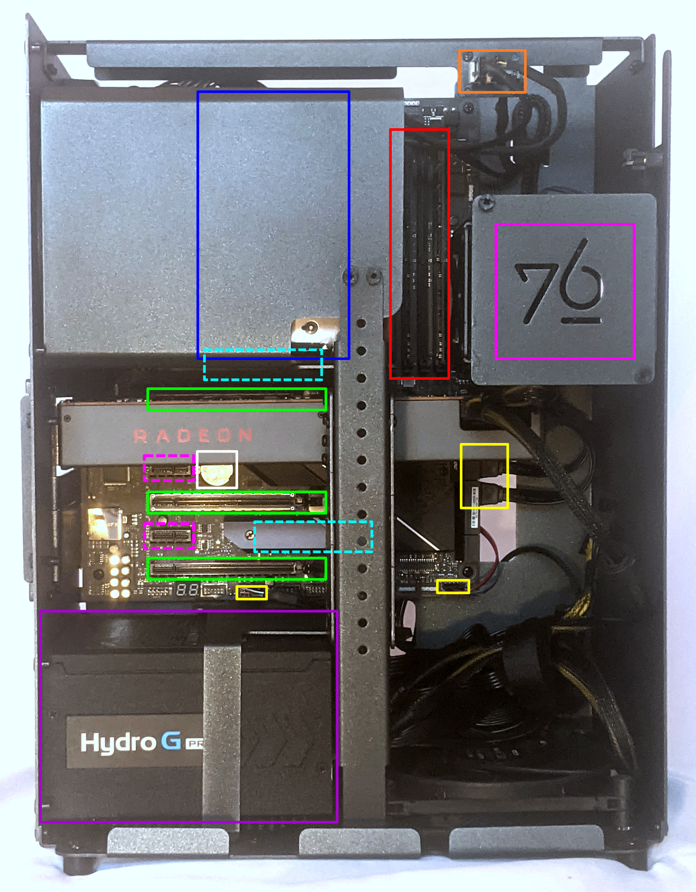
- CPU cooler is highlighted in blue
- RAM slots are highlighted in red
- PCIe x16 slots are highlighted in green
- Note: the bottom PCIe slot only supports 1u height PCIe cards.
- PCIe x1 slots are highlighted in dashed pink
- M.2 slots are highlighted in dashed cyan (located underneath the M.2 heatsinks)
- 2.5" SATA drive bays are highlighted in pink
- Power supply is highlighted in purple
- Thelio-IO to motherboard connections are highlighted in yellow
- CPU fan connectors are highlighted in orange
- CMOS battery is highlighted in white
PCIe slot guide:
From top to bottom:
- PCIe Gen 4 x16 slot (GPU 1)
- PCIe Gen 4 x1 slot
- PCIe Gen 4 x16 slot (GPU 2)
- PCIe Gen 4 x1 slot
- PCIe Gen 4 x16 slot (1u cards only)
See the repairs page for detailed information about installing or replacing components.
Thelio Mira (Parts & Repairs)
Many components in your Thelio Mira can be upgraded or replaced as necessary. Power the machine off, switch off the power supply, and unplug all peripherals before working with any internal components. Then, follow these step-by-step guides for instructions:
- Removing the top case
- Adding/removing 2.5" storage drives
- Replacing a GPU
- Replacing the M.2 drives
- Removing the CPU duct
- Replacing the RAM
- Replacing the CPU fans
- Replacing the CPU cooler/thermal paste and CPU
- Replacing the power supply
- Replacing the bottom case fan
- Replacing the Thelio-IO board
- Troubleshooting the power button
- Troubleshooting the Thelio-IO USB connection
Removing the top case:
The top case can be removed to access the internal components.
Tools required: Cross-head (Phillips) screwdriver (optional)
Time estimate: 2 minutes
Difficulty: Easy ●
Steps to remove the top case:
- Remove the eight outer screws holding the top case onto the machine.

- Slide the top case up and off of the machine.
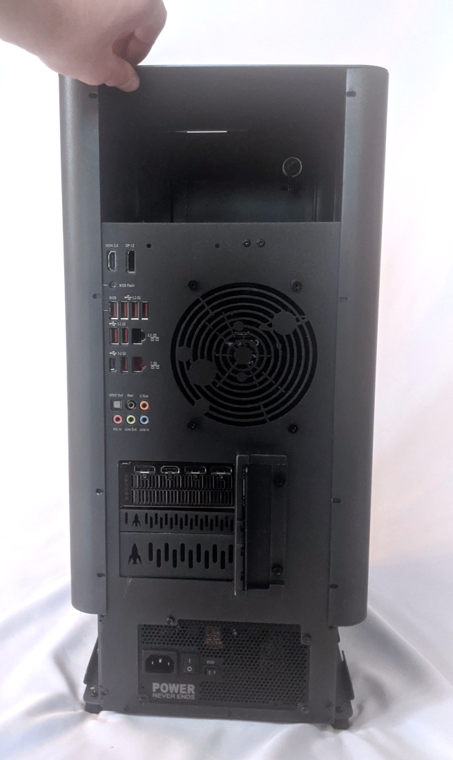
Adding/removing 2.5" storage drives:
Thelio Mira r1.0 supports up to four 2.5" SATA III drives.
Tools required: Cross-head (Phillips) screwdriver (optional)
Time estimate: 10 minutes
Difficulty: Easy ●
Steps to add/remove 2.5" storage drives:
- Follow the steps above to remove the top case.
- If you are adding a new drive, pop out the black plastic ring on the top crossbar and remove four screws (per drive).
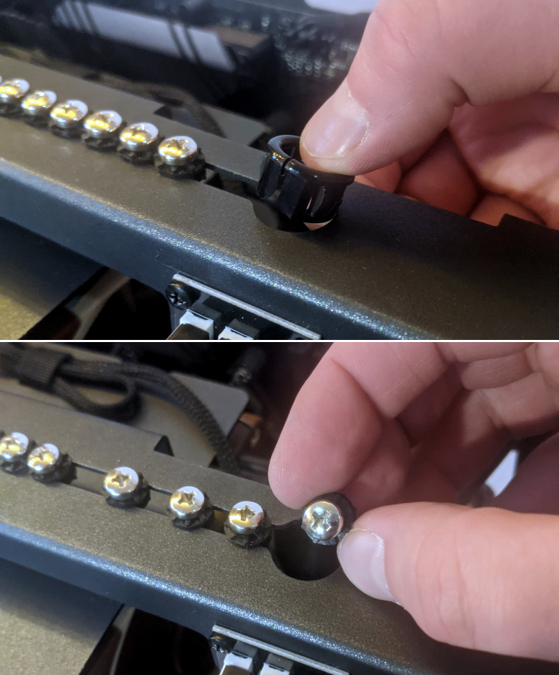
- Insert four screws into each 2.5" storage drive you wish to install.
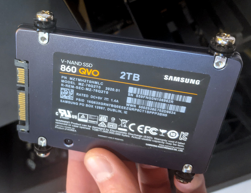
- Unscrew the two screws securing the drive bay's cover.
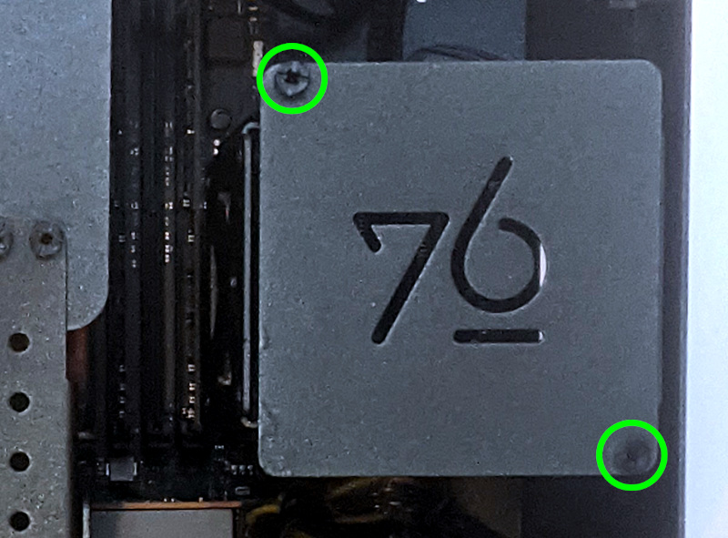
- Slide each 2.5" drive into one of the slots leading to the Thelio-IO board.
Replacing a GPU:
Depending on which power supply is installed, Thelio Mira supports up to two 3-slot thick GPUs. There are three PCIe 4.0 x16 slots; however, the bottom slot only has room for a 1-slot thick card, and is only accessible if the second slot does not have a 3-slot thick card installed. The top two slots can accommodate cards as wide as 3-slots. An even thicker GPU can be installed in the top slot if only a single GPU is being used. Mixing NVIDIA and AMD GPUs is not recommended.
Tools required: Cross-head (Phillips) screwdriver
Time estimate: 15 minutes
Difficulty: Easy ●
Steps to replace a GPU:
- Follow the steps above to remove the top case.
- Unscrew the two back screws holding the PCIe bracket in place, then slide the PCIe bracket open.
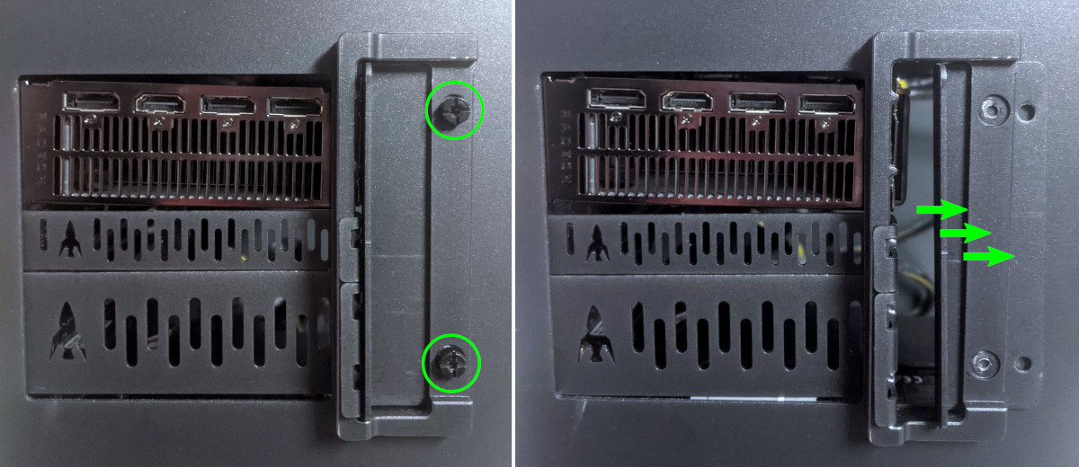
- Unscrew the four screws holding the side GPU brace in place and remove the brace.
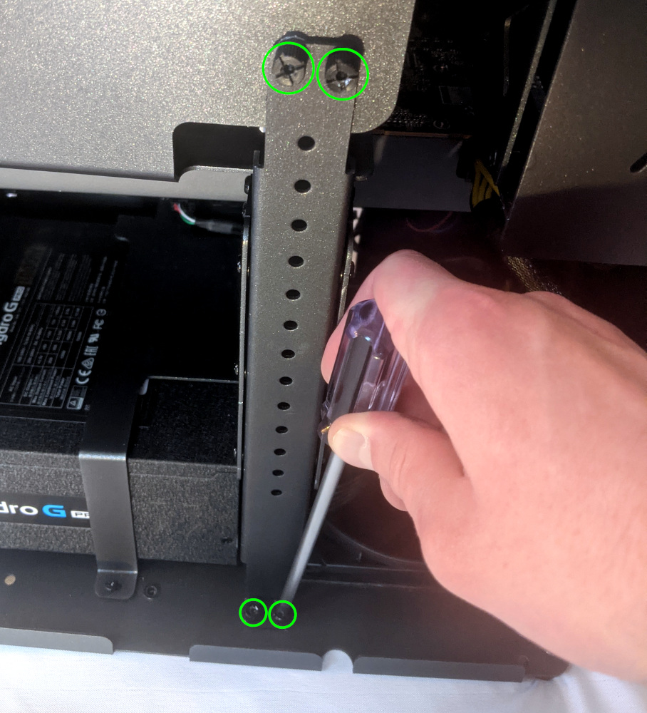
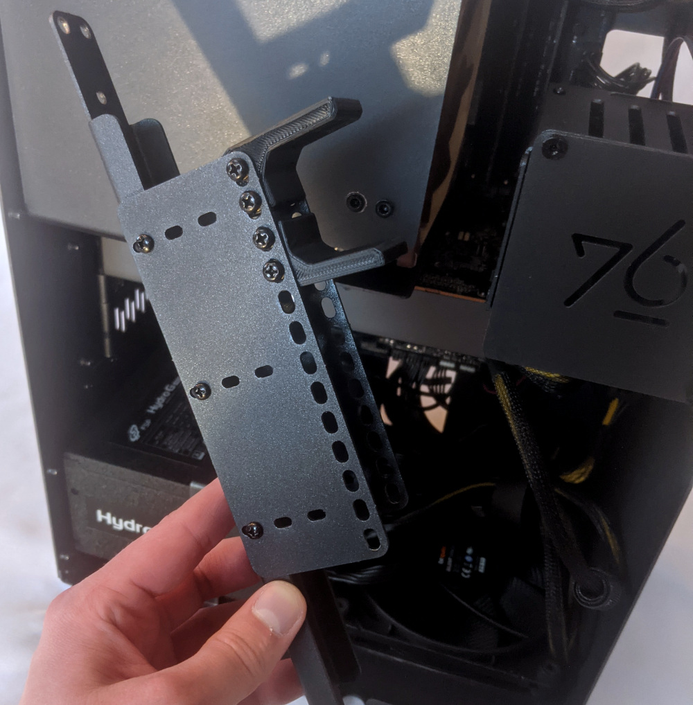
- If you're removing a GPU, unplug the GPU power cable from the right side of the card. Hold down the latch on the connector while unplugging the cable.
- Hold the latch on the motherboard to free the PCIe connection, then pull the card out of the slot.
- If removing a GPU in the bottom slot, it may be necessary to remove the GPU in the top slot first in order to reach the bottom slot's latch.
- If space is tight, a long object such as a screwdriver can be used to press the latch.

- After inserting the new GPU into its slot, connect the power cables.
- If you are using only one GPU, it should go in the top PCIe slot.
- If your Mira was originally equipped with fewer than 2 GPUs, power cables for two GPUs will still be preinstalled in your system. If they were not being used, they will be bundled up using velcro cable keepers to keep them out of the way.
- Once all GPUs are installed, replace the GPU brace, back PCIe bracket, any PCI slot covers for empty slots, and finally the top case.
- The GPU brace includes plastic pieces which are adjusted to the GPUs that originally shipped with the system. The brace is highly adjustable and should be able to accommodate many different GPU shapes and sizes.
The GPU brace's primary function is to prevent damage during shipping. The system can be run without the brace if it doesn't fit an upgraded card; the back PCIe bracket provides primary support for the GPUs.
Replacing the M.2 drives:
Thelio Mira has two M.2 slots, which support PCIe NVMe Gen 4 x4, PCIe NVMe Gen 3 x4, or SATA III. Both slots support drive sizes 22110, 2280, 2260, and 2242.
Tools required: Cross-head (Phillips) screwdriver
Time estimate: 23 minutes
Difficulty: Medium ●
Steps to replace the M.2 drives:
- Follow the steps above to remove the top case and remove the GPU brace and GPUs.
- Remove the two screws securing the M.2 fan cover and remove the fan cover.
- Remove the two screws securing the heatsink covering the slot you wish to access and remove the heatsink.

If there is already a drive in the slot you are accessing, it may take some pressure to remove the heatsink and thermal tape from the M.2 drive. Pull slowly to avoid breaking the thermal tape.
- Unscrew the retainer screw opposite the M.2 slot.
- Remove the existing M.2 drive by pulling it out of the slot.
- Insert the new M.2 drive into the slot and hold it in place.
- Replace the retainer screw.
- If utilizing a slot for the first time, peel the plastic backing off of the heatsink to expose the double-sided thermal tape for that slot.

- Replace the M.2 heatsinks, M.2 fan cover, GPUs, GPU brace, and top case.
Replacing the RAM:
Thelio Mega r1.0 supports up to 128GB (4x32GB) of RAM. The RAM sticks are Unregistered/Unbuffered ECC DDR4 DIMMs running at a speed of 3200MHz. If you've purchased new RAM, need to replace your RAM, or are reseating your RAM, follow these steps.
Tools required: Cross-head (Phillips) screwdriver (optional)
Time estimate: 20 minutes
Difficulty: Medium ●
Steps to replace the RAM:
- Follow the steps above to remove the top case.

The CPU duct has been removed for better visibility in the above photo; removing the CPU duct is not required to access the RAM slots.
- To remove an existing RAM stick, flip the top latch up away from the stick, then pull the stick out of the slot, starting from the top edge. (The bottom of the RAM slot does not move.)
- Make sure the latch on the top of the slot is open (pulled upwards), then insert the new RAM (or re-seat the existing RAM) into the slot.
- The RAM stick will only fit in one direction. The larger group of pins goes on top.
- Use the following guide for placement of the RAM sticks:
- Replace the top case.
Removing the CPU duct:
The CPU duct guides airflow through the CPU cooler.
Tools required: Cross-head (Phillips) screwdriver (optional)
Time estimate: 7 minutes
Difficulty: Easy ●
Steps to remove the CPU duct:
- Follow the steps above to remove the top case and remove the GPU brace.
- Unplug the connector for the CPU duct-mounted fan.
- Both fan connectors can be unplugged if it is difficult to tell which plug is for which fan.
- Unscrew the four back screws holding the CPU duct in place.

- Pull the CPU duct away from the machine.
Replacing the CPU fans:
Thelio Mira contains two CPU fans. One is mounted on the CPU duct, and one is mounted on the cooler.
Tools required: Cross-head (Phillips) screwdriver
Time estimate: 15 minutes
Difficulty: Medium ●
Steps to replace the duct-mounted CPU fan:
- Follow the steps above to remove the top case, remove the GPU brace, and remove the CPU duct.
- To remove the CPU duct fan, unscrew the four fan screws inside the duct.
- Free the cable from the cable keeper, then remove the fan.
Steps to replace the cooler-mounted CPU fan:
- Follow the steps above to remove the top case, remove the GPU brace, and remove the CPU duct.
- Pull the center loop of the fan clip to remove it from the CPU cooler.
- Repeat the process for the bottom clip, then remove the fan from the CPU cooler.
- Unplug the fan from the CPU fan power board (if it wasn't already unplugged when the CPU duct was removed).
- When reinstalling the CPU fans, both fans should be oriented so the side with the non-spinning cover faces the back of the machine, while the spinning side faces the front of the machine.
Replacing the CPU cooler and CPU:
The CPU cooler dissipates heat from the CPU to the heatsink, where the CPU fans expel it from the system. Depending on your climate and the age of the machine, replacing the thermal paste between the CPU and the cooler/heatsink may help the system run cooler.
The CPU uses an AMD AM4 socket.
Tools required: Cross-head (Phillips) screwdriver, thermal paste
Time estimate: 35 minutes
Difficulty: High ●
Steps to remove the CPU cooler/thermal paste:
- Follow the steps above to remove the top case, remove the GPU brace and GPUs, remove the CPU duct, and remove the cooler-mounted CPU fan.
- While holding the CPU cooler in place so it doesn't fall, unscrew the two CPU cooler mounting screws. The cooler brackets are under spring tension, so it's best to loosen each side a little at a time.

- The cooler will come away from the CPU.
- Using a paper towel, clean the existing thermal paste off of the heatsink and CPU. You may also use a small amount of rubbing alcohol if the old paste is dried or difficult to remove.
Steps to replace the CPU:
- Flip the CPU locking lever up to unlock the CPU socket.
- Carefully lift the CPU straight out of the socket.
- Caution: The CPU has hundreds of tiny, delicate pins on the bottom side, so be very careful not to bend any of them while uninstalling, handling, or installing the CPU.
- The top left corner on the CPU socket has a triange indicator to mark the direction the CPU should be oriented. Using this as a guide, carefully place the new CPU into the socket, matching the triangle on the CPU with the triangle on the motherboard.
- Lower the CPU locking lever back down into the locked position.
Steps to install the thermal paste/CPU cooler:
- Place a small blob of thermal paste onto the CPU.

- Place the CPU cooler over the CPU, aligning the two screws on the CPU cooler with the studs on the mounting brackets, and tighten the screws.
- To distribute the thermal paste evenly across the CPU, tighten each screw a little bit at a time.
- Reinstall the cooler-mounted CPU fan, CPU duct, GPUs, GPU bracket, and top case.
Replacing the power supply:
Your Thelio Mira is equipped with one of three different power supplies. All three power supply units (PSUs) are modular and can be replaced with another unit of the same model. Different models may not be compatible with the cabling pre-installed in the Thelio Mira.
Note: The PSU shown in these photos is not a model that Thelio Mira is being equipped with at the time of writing these instructions. Be sure to confirm which PSU model your machine has before seeking a replacement.
Tools required: Cross-head (Phillips) screwdriver
Time estimate: 30 minutes
Difficulty: High ●
Steps to replace the power supply:
- Follow the steps above to remove the top case and remove the GPU brace.
- Unplug all of the modular cabling from the back of the PSU.
- Some of the cables may be easier to unplug after the PSU has been unscrewed/removed from the case.
- Unscrew the PSU bracket from the reverse side of the case.

- Unscrew the PSU bracket from the bottom of the case.

- Remove the PSU bracket.
- Unscrew the four screws holding the PSU in from the back of the case.

- Remove/replace the PSU. Set the replacement PSU on top of the rubber post that holds it at the correct height.
- The replacement PSU should be installed with the fan facing the bottom of the case.
- After screwing in the replacement PSU and replacing the PSU bracket, use the labels and pin counts on the cables and ports to ensure the power cables are reconnected in the proper locations.
- Remember that not all of the available connectors will plug into the PSU-- four connectors (on two cables) are to be plugged into the GPUs.
- If the replacement PSU has an "ECO Mode" switch, make sure it is switched on.
Replacing the bottom case fan:
Thelio Mira r1.0 has one intake fan mounted in the bottom of the case.
Tools required: Cross-head (Phillips) screwdriver
Time estimate: 15 minutes
Difficulty: Medium ●
Steps to replace the bottom case fan:
- Follow the steps above to remove the top case.
- Disconnect the fan's cable from the Thelio-IO daughterboard and remove the cable from the cable keeper bundles. The fan connector can be accessed through the cutout in the front of the chassis.
- Unscrew the four fan screws from the bottom of the machine, then remove the fan from the case. The chassis can be laid on its back to make it easier to access these screws.
- The components should be mounted to the chassis in the following order:
- Dust filter
- Acrylic spacer
- Fan
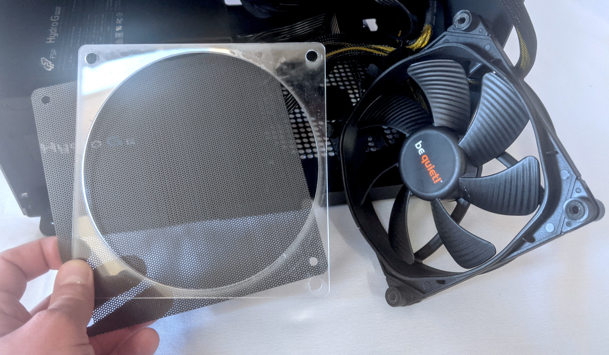
Replacing the Thelio-IO board:
The Thelio-IO board handles the front power button, fan control, and 2.5" SATA connectors for the system. If the Thelio-IO board becomes defective, it can be replaced using the instructions below.
Tools required: Cross-head (Phillips) screwdriver
Time estimate: 15 minutes
Difficulty: High ●
Steps to replace the Thelio-IO board:
- Follow the steps above to remove the top case and remove the front cover and any installed drives from the 2.5" drive bays.
- Use the cutout on the front side of the chassis to unplug all cabling from the Thelio-IO board that is being replaced, including the SATA cables.
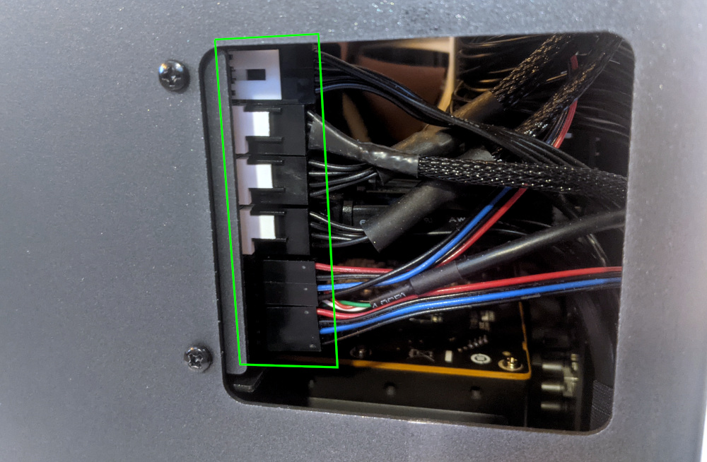
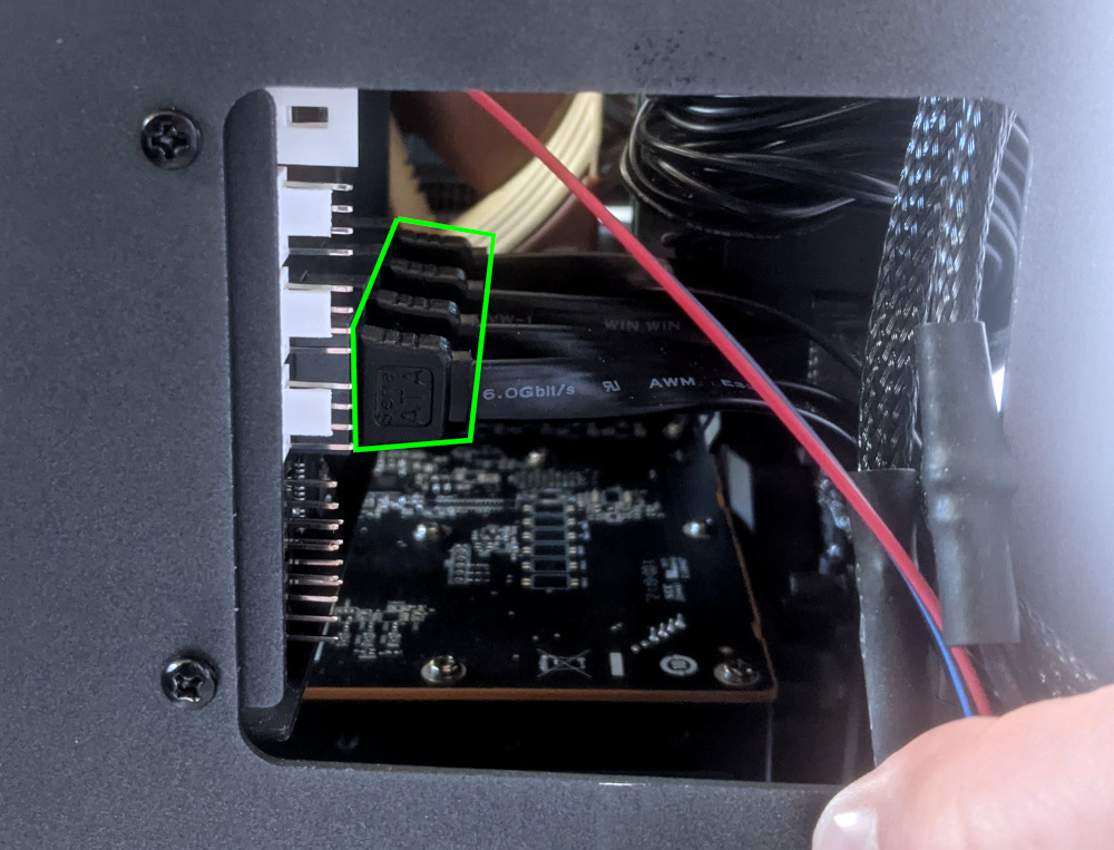
- Unscrew the four screws on the front of the chassis that secure the 2.5" drive cage and remove it from the chassis. Hold the drive cage when removing the final screw to keep it from falling.
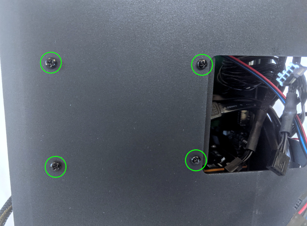
- Remove four screws on either side of the drive cage to free the Thelio-IO board from the cage.
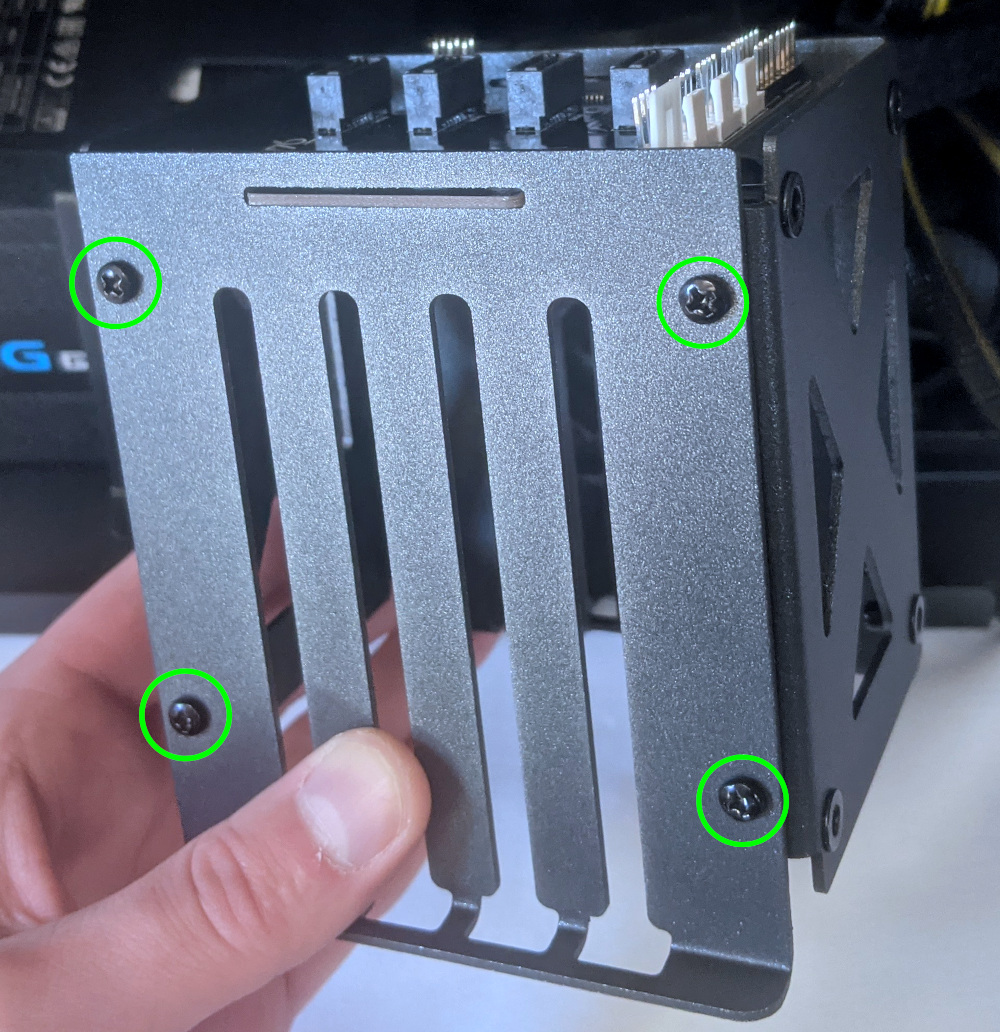
- Place the new Thelio-IO board into the drive cage, reassemble the drive cage, mount the drive cage back into the chassis, and replace all cables. Below are references for the correct cable orientations:
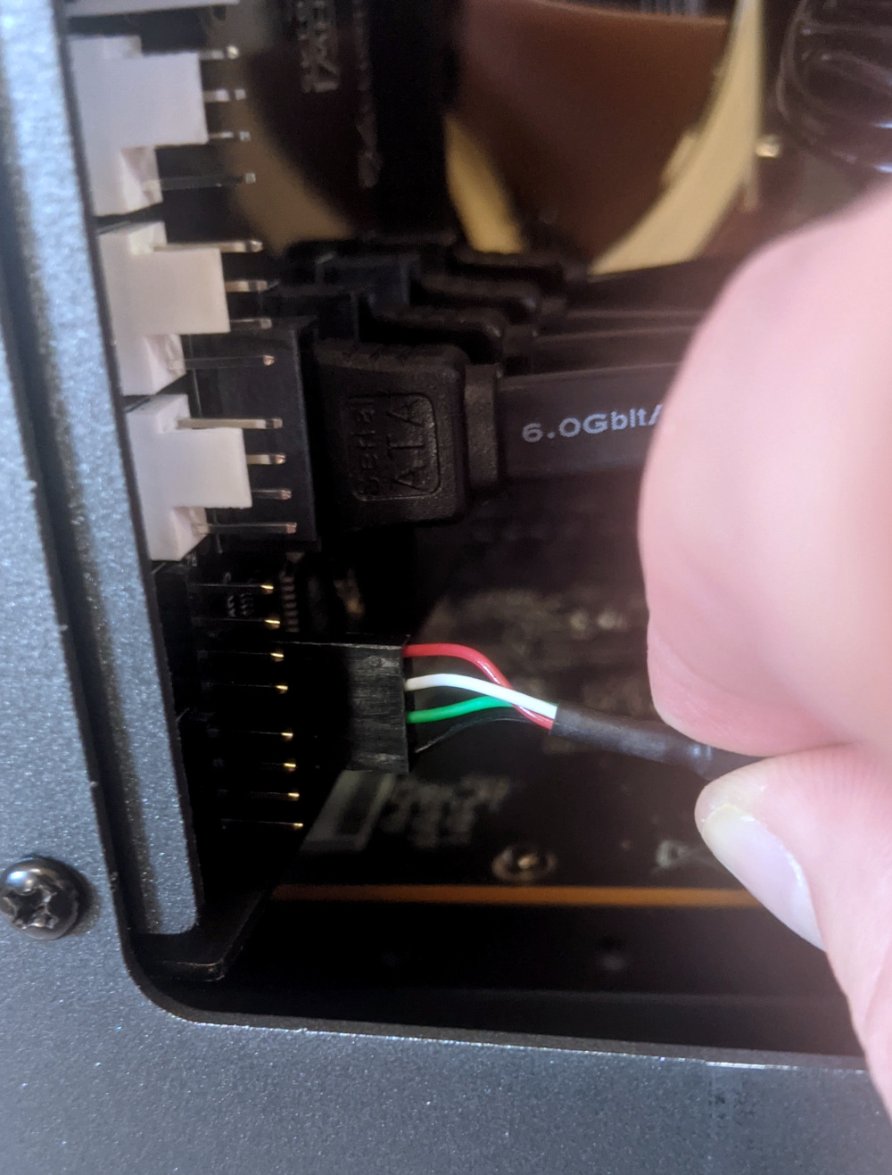

Troubleshooting the power button:
If the front power button doesn't power the machine on or doesn't light up when the system is powered on, try the following troubleshooting steps:
- Ensure the system powers on normally using the internal power button.
- Reseat the front power button to ensure it's making proper contact.
- Check the wiring for the front power button.
- Replace the front power button, if necessary.
Tools required: Cross-head (Phillips) screwdriver (optional)
Time estimate: 15 minutes
Difficulty: Medium ●
Steps to power the machine on using the internal power button:
- Follow the steps above to remove the top case.
- Ensure the system is plugged into power, and the power supply switch is in the 1 (On) position.
- Push the small button labeled
B0on the Thelio-IO board.

- If the Thelio-IO
B0button powers the machine on, then the issue is either the front power button or its connection to the Thelio-IO board. Check the front power button wiring. - If the Thelio-IO
B0button does not work, then the issue is either the Thelio-IO board or its connection to the motherboard. Check the wiring between the Thelio-IO board and the motherboard. - If all Thelio-IO and power button connections are hooked up correctly, then the issue may be the motherboard, or it may be the power supply or its connection to the motherboard. Ensure all connections are plugged in properly and that the power supply is switched to the 1 (On) position.
Steps to check the front power button wiring:
- Follow the steps above to remove the top case and remove the GPU brace. If a second GPU is installed, removing it will make it easier to access the connections on the motherboard.
- On the back of the power button, the four pins should be connected to the four-wire connector as follows:

- On the front power button receptacle, the four-pin connector should have the red wire on the left and the black wire on the right.

- The front power button receptacle should plug into the
PFPDport on the top Thelio-IO board, with the red wire on the bottom and the black wire on the top.

- The
PMBDport on the Thelio-IO board should connect to the headers on the bottom right corner of the motherboard, as shown below:
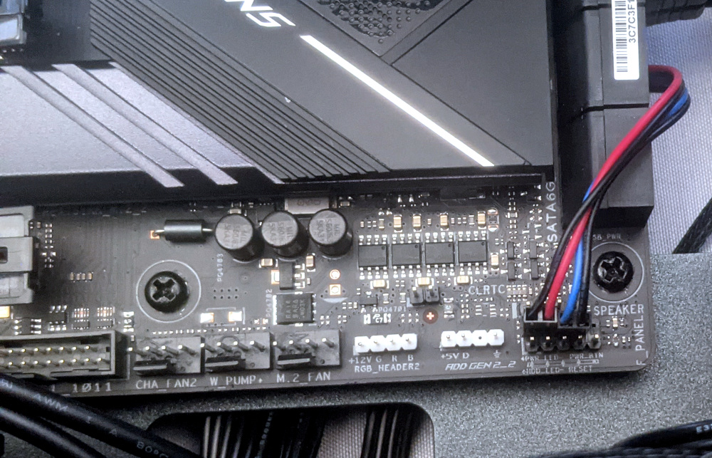
Steps to replace the power button:
- Follow the steps above to remove the top case.
- Follow the instructions in the Replace the Thelio Power Button support article.
Troubleshooting the Thelio-IO USB connection:
The Thelio-IO boards connect to the motherboard's USB headers for firmware updates and fan control within the host OS. If the fans seem to be stuck on full blast, check the Thelio-IO USB connections.
Tools required: Cross-head (Phillips) screwdriver (optional)
Time estimate: 10 minutes
Difficulty: Medium ●
Steps to check the USB wiring:
- Follow the steps above to remove the top case and remove the GPU brace. If a second GPU is installed, removing it will make it easier to access the connections on the motherboard.
- The Thelio-IO board has a
USB0port. The port connects to a cable (labeledUSB) with the red wire on the top.
 Note: The fan and power button cables have been unplugged in this picture to make it easier to see the USB connector on Thelio-IO.
- The
USB0port on the Thelio-IO board should connect to the USB header in the center of the bottom edge of the motherboard, as shown below:
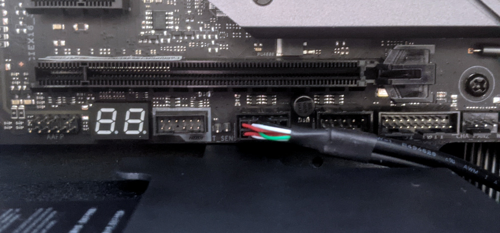
Thelio Spark (thelio-spark-b1-n2)
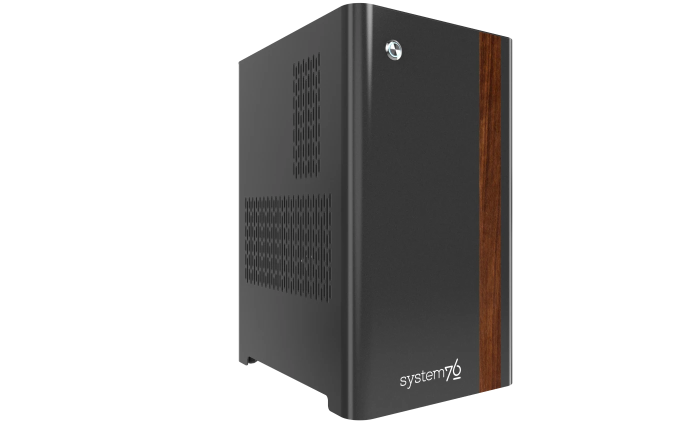
The System76 Thelio Spark is a desktop with the following specifications:
- Chassis
- System76 Thelio Spark chassis based on nebula36-2
- Processor options
- Supports Intel 12th Generation (Alder Lake) CPUs
- Motherboard
- ASRock B660M PRO RS running System76 Firmware (non-open)
- Intel B660 chipset
- Daughterboard
- Thelio Io board running open-source firmware
- Graphics options
- Up to two dedicated GPUs
- Primary GPU slot:
- PCIe 4.0 x16
- Up to 3-slot height
- Up to 2-slot height if PCIe x1 slot is in use
- Secondary GPU slot:
- PCIe 3.0 x16
- Up to 4-slot height
- Primary GPU slot:
- GPU size:
- Internal clearance: 318.80mm
- Recommended maximum length: 308.80mm
- Tested with the following GPUs:
- Integrated Graphics
- 1x HDMI 2.1, 1x DisplayPort 1.4
- AMD Radeon RX 7600
- 1x HDMI 2.1, 3x DisplayPort 2.1
- NVIDIA GeForce RTX 4060 Ti
- 1x HDMI 2.1, 3x DisplayPort 1.4a
- Integrated Graphics
- Up to two dedicated GPUs
- Expansion
- 1x PCIe 4.0 x16 (primary GPU slot)
- 1x PCIe 3.0 x16 (secondary GPU slot)
- 1x PCIe 3.0 x1
- Memory
- Up to 64GB (4x16GB) dual-channel DDR4 DIMMs @ 3200 MHz
- User-expandable up to 128GB (4x32GB) @ 3200 MHz
- Tested with the following RAM modules (may ship with other tested modules):
- Crucial CT16G4DFRA32A (16GB/stick)
- Up to 64GB (4x16GB) dual-channel DDR4 DIMMs @ 3200 MHz
- Networking
- 1x 1-Gigabit Ethernet (Intel I219-V)
- 1x PCI Express x1 wireless card (Intel AX210)
- WiFi 6E
- Bluetooth 5.2
- Power
- C13 power cord
- 600W PSU
- Tested with the following PSU models (may ship with other tested models):
- Sound
- Back: 3.5mm line out, line in, microphone jacks
- Top: 3.5mm line out, microphone jacks
- Up to 7.1-channel audio output
- Realtek ALC897 audio chipset
- HDMI, DisplayPort audio
- Storage
- 1x M.2 2280/2260/2242 SSD
- PCIe NVMe Gen 4
- 1x M.2 2280 SSD
- PCIe NVMe Gen 3
- SATA III
- Intel Optane
- 2x 2.5" (15mm) SATA III
- 1x M.2 2280/2260/2242 SSD
- USB
- 1x USB 3.2 Gen 1 Type-C
- Top port
- 5x USB 3.2 Gen 1 Type-A
- 4x back ports, 1x top port
- 2x USB 2.0 Type-A
- Back ports
- 1x USB 3.2 Gen 1 Type-C
- Dimensions
- 43.635cm × 25.3cm × 33.1cm
Thelio Spark (External Overview)
Back overview:

Power Switch Guide:
- 0: Off
- 1: On
PCI Express Slot Guide:
The recommended PCIe slot configuration is:
- Top slot (4.0 x16): Used for dedicated GPU (if ordered)
- Middle slot (3.0 x1): Empty
- Bottom slot (3.0 x16): Used for wireless card
Cards can be moved into other compatible slots to accomplish different aftermarket configurations. Note that the wireless card may obstruct the GPU fans if placed in the middle PCIe slot (3.0 x1).
Front/side overview:

Top/bottom overview:

Thelio Spark (Internal Overview)
Left side overview:
Chassis components:

- CPU duct is highlighted in red
- 2.5" drive cage is highlighted in pink
- Side brace is highlighted in green
Electronic components:

- CPU heatsink is highlighted in yellow
- RAM slots are highlighted in green
- 2.5" SATA slots are highlighted in pink
- M.2 slots are highlighted in cyan
- GPU (in PCIe 4.0 x16 slot) is highlighted in red
- Wireless card (in PCIe 3.0 x16 slot) is highlighted in white
- Power supply is highlighted in maroon
- Bottom case fan is highlighted in orange
Right side overview:

- Thelio Io connector access cutout is highlighted in green
- Power supply access cutout is highlighted in red
Front side overview:

- Thelio Io connector access cutout is highlighted in green
- Internal power button (on the Thelio Io board) is highlighted in cyan
Top overview:

- CPU power connector is highlighted in red
- Connects to power supply
- Motherboard CPU fan header is highlighted in yellow
- Connects to Thelio Io board
- CPU fan splitter is highlighted in pink
- Connects to Thelio Io board and CPU fans
- Top I/O board is highlighted in white
- Connects to motherboard
- 2.5" drive screws are highlighted in green
- Power button receptacle is highlighted in cyan
- Connects to Thelio Io board
See the repairs page for detailed information about installing or replacing components.
Thelio Spark (Parts & Repairs)
Many components in your Thelio Spark can be upgraded or replaced as necessary. This page uses photos of the the B1-N2 revision, which indicates:
- B1: The first Intel motherboard model used in Thelio Spark.
- N2: Based on the second revision of the nebula36 chassis.
Minor case details may vary based on the production date of the unit, but screw counts, general component locations, and other details should remain the same unless otherwise noted.
Power the machine off, switch off the power supply, and unplug all peripherals before working with any internal components. Then, follow these step-by-step guides for instructions:
- Replacing the front accent strip
- Removing the top case
- Adding/removing 2.5" storage drives
- Removing the side brace
- Replacing the bottom case fan
- Removing the CPU duct
- Replacing the GPU
- Replacing the CMOS battery
- Replacing the wireless card
- Replacing the RAM
- Replacing the M.2 drives
- Replacing the CPU fans
- Replacing the CPU cooler/thermal paste and CPU
- Replacing the power supply
- Replacing the Thelio Io board
- Replacing the SATA backplane
- Replacing the top I/O
- Troubleshooting the power button
Replacing the front accent strip:
Thelio Spark includes a customizable accent panel on the front of the case, which can be swapped to change the case's look and feel. The instructions for swapping the accent are also available in video form.
Tools required: None
Time estimate: 30 seconds
Difficulty: Easy ●
Steps to replace the front accent strip:
- Place the Thelio on the edge of the desk so the front side is hanging off of the desk.
- The Thelio can alternatively be lifted or tilted so the front of the computer is hovering above the desk.
- Slide the accent strip down to unlock it.
- The accent can be gripped at the bottom edge.
- Pull the accent strip off of the case, starting with the bottom edge.
- Place the new accent strip onto the front of the case and slide it up to lock it into place.

Removing the top case:
The top case can be removed to access the internal components.
Tools required: Cross-head (Phillips) screwdriver (optional)
Time estimate: 2 minutes
Difficulty: Easy ●
Steps to remove the top case:
- Remove the four outer screws holding the top case onto the machine.

- Slide the top case up and off of the machine.
Adding/removing 2.5" storage drives:
Thelio Spark B1-N2 supports up to two 2.5" SATA III drives.
Tools required: Cross-head (Phillips) screwdriver
Time estimate: 7 minutes
Difficulty: Easy ●
Steps to add/remove 2.5" storage drives:
- Follow the steps above to remove the top case.
- Unscrew the two screws securing the drive bay's cover, highlighted green below.

- If you are adding a new drive, pop out the black plastic ring on the top crossbar and slide out four screws (per drive).

- Insert four screws into each 2.5" storage drive you wish to install.
- Slide each 2.5" drive into one of the slots leading to the SATA backplane.


- Replace the black plastic screw ring and the 2.5" drive bay cover.
Removing the side brace:
The side brace provides a mounting point for the GPU brace finger, which helps keep GPUs or other PCI Express cards in place during shipping. It also provides mounting points for two 120mm fans, which are not offered as part of Thelio Spark but can optionally be installed as an aftermarket upgrade.
The GPU brace finger is only required during shipping. The system can be run without this part if it does not fit an upgraded GPU.
Tools required: Cross-head (Phillips) screwdriver
Time estimate: 15 minutes
Difficulty: Easy ●
Steps to remove the side brace:
- Follow the steps above to remove the top case.
- Unscrew the four screws holding the side bracket in place (two on the front of the case, two on the back.)

- Pull the side brace out of the chassis. Unplug the side fan connector from the splitter board on the right side, if connected.
Steps to adjust the GPU brace finger:
- Follow the steps above to remove the top case and remove the side brace.
- To adjust the GPU brace finger's horizontal position, unscrew the four corner screws (highlighted green below), move the GPU brace finger's mounting bar, and reattach it in the desired position.
- The center vertical adjustment screw (highlighted cyan below) may also need to be removed or loosened.

- To adjust the GPU brace finger's vertical position, unscrew the three vertical adjustment screws, move the GPU brace finger, and reattach it in the desired position.

Replacing the bottom case fan:
Thelio Spark B1-N2 has one case-mounted intake fan on the bottom of the chassis. The fan is a 140mm Be Quiet! Silent Wings 4 (model number BQ SIW4-14025-MF-PWM).
Tools required: Cross-head (Phillips) screwdriver
Time estimate: 20 minutes
Difficulty: Medium ●
Steps to replace the bottom case fan:
- Follow the steps above to remove the top case.
- The side brace can optionally be removed to provide easier access to the fan and its cabling.
- Unplug the fan's cable from the Thelio Io daughterboard.
- The bottom case fan plugs into the
INTAKE FANport on the Thelio Io board. - When viewed from the access cutout on the side of the case, this connector is second from the bottom, next to the
FANOUT1port.- The
FANOUT1port (highlighted red below) can be unplugged for easier access to theINTAKE FANport (highlighted green below).
- The
- The bottom case fan plugs into the

- Unscrew the four fan screws from the bottom of the machine.
- To avoid damaging other components, place the machine on its front side when working with the bottom surface.
- A soft surface such as a towel can optionally be used to protect the work surface and the machine.

- Remove the old fan from the case.
- When installing the fan, mount the components in the following order:
- Chassis
- Dust filter
- Acrylic spacer
- Fan
- The new fan's cable should be oriented towards the front-right corner of the case.
- The cable runs along the inner corner of the case, passing through the bottom two velcro straps twice (left through both, then right through both) and the higher two velcro straps once.

Removing the CPU duct:
The CPU duct guides airflow through the CPU cooler. It covers the CPU and partially obstructs the RAM slots and top PCIe slot.
Tools required: Cross-head (Phillips) screwdriver
Time estimate: 7 minutes
Difficulty: Easy ●
Steps to remove the CPU duct:
- Follow the steps above to remove the top case and remove the side brace.
- The GPU can also optionally be removed to provide more room for working with the components.
- Unplug the braided connector for the duct-mounted CPU fan from the top splitter board in the front corner of the machine.
- The splitter board provides the same signal to both ports, so it doesn't matter which fan is plugged into which port.

- Unscrew the four back thumbscrews and two top crossbar screws holding the CPU duct in place.


- Pull the CPU duct away from the machine.
Replacing the GPU:
Thelio Spark ships with an optional dedicated GPU in the PCIe 4.0 x16 slot (top slot). Factory-installed GPUs are two slots tall, but the fans may extend slightly into the third slot's space. Aftermarket GPUs can be up to three slots tall; GPUs higher than three slots tall require removing the wireless card to fit.
If the wireless card is removed and the first GPU is three or fewer slots tall, then a second GPU can be installed in the PCIe 3.0 x16 slot (bottom slot) as an aftermarket upgrade.
Tools required: Cross-head (Phillips) screwdriver
Time estimate: 15 minutes
Difficulty: Medium ●
Steps to replace the GPU:
- Follow the steps above to remove the top case and remove the side brace.
- You can optionally remove the CPU duct for easier access to the PCIe slot and power cable latches.
- If you're removing a GPU, unplug the GPU power cable from the right side of the card. Hold down the latch on the connector while unplugging the cable.

- Unscrew the two back screws holding the PCIe bracket in place, and remove the PCIe bracket (or slide it into the rightmost position).

- Push back the latch on the motherboard to free the PCIe connection, then pull the card out of the slot.
- If the latch is difficult to reach between the GPU and the CPU heatsink, a long object (such as a screwdriver) can be used to push the latch.

- After inserting the new GPU into its slot, connect the power cable.
- Once the GPU is installed, replace the back PCIe bracket, side brace, and top case.
- The GPU brace finger may need to be adjusted before the side brace can be reinstalled.
Replacing the CMOS battery:
The CMOS battery supplies power to the system's CMOS chip. UEFI settings and the computer's hardware clock are stored on the CMOS. If your system doesn't boot, you can reset the CMOS to force a low-level hardware reset. If your clock is constantly resetting, it's likely your CMOS battery needs to be replaced.
Warning (ingestion hazard): Keep batteries out of reach of children. Death or serious injury can occur if ingested. If a battery is suspected to be swallowed or inserted inside any part of the body, seek immediate medical attention. In the US, you can also call the National Battery Ingestion Hotline for guidance: 1 (800) 498-8666
Tools required: Cross-head (Phillips) screwdriver
Time estimate: 20 minutes
Difficulty: Medium ●
Steps to replace the CMOS battery:
- Follow the steps above to remove the top case, remove the side brace, and remove the GPU.
- Pull the clip away from the CMOS battery.

- Pull the CMOS battery out of its slot.
- If you are resetting the CMOS, hold down the power button for 10 seconds to discharge any residual energy in the system.
- Replace the CMOS battery starting with the left side of the slot (opposite from the clip).
- The positive side of the battery (with text) should face outward.
- Replace the GPU, side brace, and top case.
Replacing the wireless card:
Thelio Spark's wireless card is a Ubit PCI Express x1 card with an Intel AX210 chipset. This chipset suppots WiFi 6E and Bluetooth 5.2. System76 installs custom external antennas that are shorter than the default Ubit antennas.
Tools required: Cross-head (Phillips) screwdriver
Time estimate: 20 minutes
Difficulty: Medium ●
Steps to replace the wireless card:
- Follow the steps above to remove the top case and remove the side brace.
- Unscrew the two back screws holding the PCIe bracket in place, and remove the PCIe bracket (or slide it into the rightmost position).

- Unplug the wireless card's data cable from the
USB_5_6port on the motherboard, highlighted yellow below.- The cable may alternatively be plugged into the adjacent
USB_3_4port.
- The cable may alternatively be plugged into the adjacent

- Remove the wireless card from the PCIe slot.
- You may need to rotate the antennas to fit them through the PCIe slot cutout in the chassis.
- Install the new wireless card or reinstall the existing wireless card into the PCIe slot, screw in the antennas (if applicable), then ensure the data cable is plugged into both the white port on the wireless card (highlighted green above) and the
USB_5_6port on the motherboard.- The cable may alternatively be plugged into the adjacent
USB_3_4port if theUSB_5_6port is occupied by another component.
- The cable may alternatively be plugged into the adjacent
- Replace the back PCIe bracket, side brace, and top case.
Replacing the RAM:
Thelio Spark B1-N2 supports up to 128GB (4x32GB) of RAM. Factory configurations are limited to 64GB (4x16GB).
The RAM sticks are DDR4 DIMMs (non-ECC) running at a speed of up to 3200MHz. With aftermarket DIMMs, overclocked speeds of up to 5333 MHz may function but are not guaranteed.
If you've purchased new RAM, need to replace your RAM, or are reseating your RAM, follow these steps.
Tools required: Cross-head (Phillips) screwdriver
Time estimate: 15 minutes
Difficulty: Medium ●
Steps to replace the RAM:
- Follow the steps above to remove the top case and remove the CPU duct.
- If there's no dedicated GPU installed, then removing the CPU duct is optional, but removal is still recommended to provide easier access to the RAM slots.
- To remove an existing RAM stick, flip the top latch away from the stick, then pull the stick out of the slot.
- The bottom of the RAM slot does not move.

- Make sure the tabs on the top and bottom of the slot are open (pulled away from the slot), then insert the new RAM (or re-seat the existing RAM) into the slot.
- The RAM stick will only fit in one direction. The larger group of pins goes on top.
- Use the following guide for placement of the RAM sticks:

- Replace the top case.
Replacing the M.2 drives:
Thelio Spark B1-N2 has two M.2 storage slots. All four slots are M-key and size 2280.
- Slot 1 supports PCIe NVMe Gen 4.
- Slot 2 supports PCIe NVMe Gen 3, SATA III, and Intel Optane.
Tools required: Cross-head (Phillips) screwdriver
Time estimate: 30 minutes
Difficulty: Medium ●
Steps to replace the M.2 drive:
- Follow the steps above to remove the top case.
- For Slot 1, remove the CPU duct.
- Removing the GPU is not required, but makes accessing Slot 1's screws easier.
- For Slot 2, remove the side brace.
- For Slot 1, remove the CPU duct.
- For Slot 1, unscrew and remove the M.2 heatsink. For Slot 2, unscrew the screw opposite from the slot.
- For Slot 1, pull the M.2 heatsink directly away from the motherboard to break the seal of the thermal tape, then slide the M.2 heatsink down and out from behind the CPU heatsink.
- For both slots, the existing M.2 drive (if installed) will pop up at a 30-degree angle from the motherboard.

- Remove the existing M.2 drive by pulling it out of the slot.
- Insert the new M.2 drive into the slot and hold it in place.
- Replace the M.2 heatsink and/or M.2 screw(s).
- Because Slot 1 is always populated in factory configurations, the M.2 thermal tape should already be applied and exposed on the M.2 heatsink. The thermal tape is shown below.

- Replace the CPU duct, GPU, side brace, and top case as applicable.
Replacing the CPU fans:
Thelio Spark B1-N2 contains two CPU fans. One is mounted on the CPU duct, and one is mounted on the CPU heatsink.
The heatsink-mounted CPU fan is built onto the cooler's plastic molding. While it can be removed, replacements generally can't be obtained separately from the heatsink.
Tools required: Cross-head (Phillips) screwdriver
Time estimate: 25 minutes
Difficulty: Medium ●
Steps to replace the duct-mounted CPU fan:
- Follow the steps above to remove the top case and remove the CPU duct.
- Free the fan cable from the velcro loop, highlighted cyan below.

- Unscrew the four screws (two on each side) holding the fan bracket onto the duct.
- Removing the bracket from the duct is not required to remove the fan, but it makes installing the fan much easier.
- Unscrew the four screws attaching the bracket to the fan.

- When reinstalling the fan into the CPU duct:
- The spinning side should face inward (towards the front of the chassis).
- The cable should point towards the closed corner of the top side of the duct (the top-right corner, when viewed from the back); the side of the fan where the cable originates should match the side of the duct with the velcro strap.
- Overtightening the fan bracket's screws may cause fan noise; if the fan is creating excessive noise, try slightly loosening some of the screws.
Steps to replace the heatsink-mounted CPU fan:
- Follow the steps above to remove the top case and remove the CPU duct.
- For easier access to the fan tabs, it's also recommended to remove the side brace and remove the dedicated GPU (if installed).
- If the heatsink-mounted fan is still plugged in, unplug it from the top splitter board in the front corner of the machine.
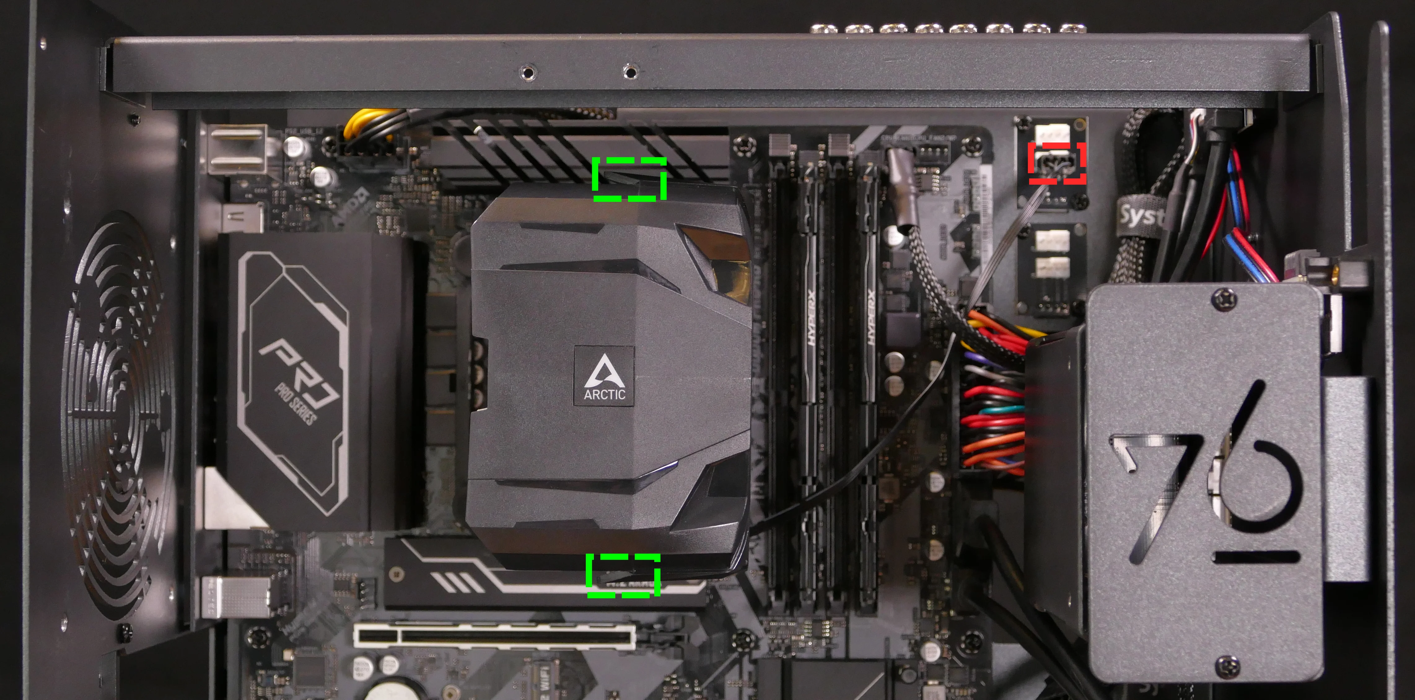
- Pull the top and bottom edges of the fan's plastic molding away from the heatsink it's clipped onto; the fan can be pulled away from the heatsink once the plastic molding's tabs are held far enough away from the heatsink.
- Repeat the process for the bottom clip, then pull the fan and clips away from the CPU heatsink.
- When reinstalling the CPU heatsink fan, the side with a stationary cover should face the heatsink, while the spinning side should face the front of the chassis.
- The cable should point towards the bottom inner corner (bottom-left when viewed from the back of the case.)
Replacing the CPU cooler and CPU:
The CPU cooler dissipates heat from the CPU to the heatsink, where the CPU fans expel it from the system. Depending on your climate and the age of the machine, replacing the thermal paste between the CPU and the cooler/heatsink may help the system run cooler.
The CPU uses an Intel LGA 1700 socket. The CPU cooler is an Arctic Freezer 7 X Rev 3.
Tools required: Cross-head (Phillips) screwdriver, thermal paste
Time estimate: 45 minutes
Difficulty: High ●
Steps to remove the CPU cooler/thermal paste:
- Follow the steps above to remove the top case, remove the side brace, remove the CPU duct, and remove the GPU.
- Unplug the heatsink-mounted CPU fan unless it's already been removed.
- While holding the CPU cooler in place so it doesn't fall, loosen the screws on the top and bottom of the CPU cooler holding it onto the mounting bracket.
- If you unscrew the screws too far, the 90-degree clips will detatch from the vertical mounting bar. Reattach them facing inwards when reinstalling the cooler.

- Pull the cooler away from the CPU, alternating between the top and bottom to free the 90-degree clips from the mounting bracket.
- Using a paper towel, clean the existing thermal paste off of the heatsink and CPU. You may also use a small amount of rubbing alcohol if the old paste is dried or difficult to remove.

Steps to replace the CPU:
- Place the computer on its side so the motherboard is facing up.
- Remove the RAM to provide easier access to the cooler mounting bracket's plastic retention pins.
- Pull the plastic retention pins out of the four corners of the cooler mounting bracket, then remove the cooler mounting bracket.

- Push the locking lever outward until it's able to spring away from the motherboard.
- Caution: the locking lever may spring up with significant force when freed.

- Flip the CPU holder away from the CPU.
- The CPU holder opens in the opposite direction from the locking lever.

- Carefully lift the CPU out of the CPU socket.
- Be careful not to bend any of the gold pins on the CPU socket, and do not touch the gold pads on the CPU.

- Gently place the new CPU into the socket.
- The triangle on the CPU should be oriented to match the triangle on the CPU cover, pointing towards the bottom left of the motherboard.
- Flip the CPU cover back onto the CPU and push the locking lever down into place.
- Reinstall the cooler mounting bracket by lining it up with the holes in the motherboard and pushing the plastic retention pins back into place.
- Ensure that the transparent sleeves in the corners of the mounting bracket are pulled outwards to the
1700position. - The orientation of the cooler mounting bracket doesn't matter. By default, the
1700number is on the top and bottom of the bracket, while the1200number is on the left and right.
- Ensure that the transparent sleeves in the corners of the mounting bracket are pulled outwards to the
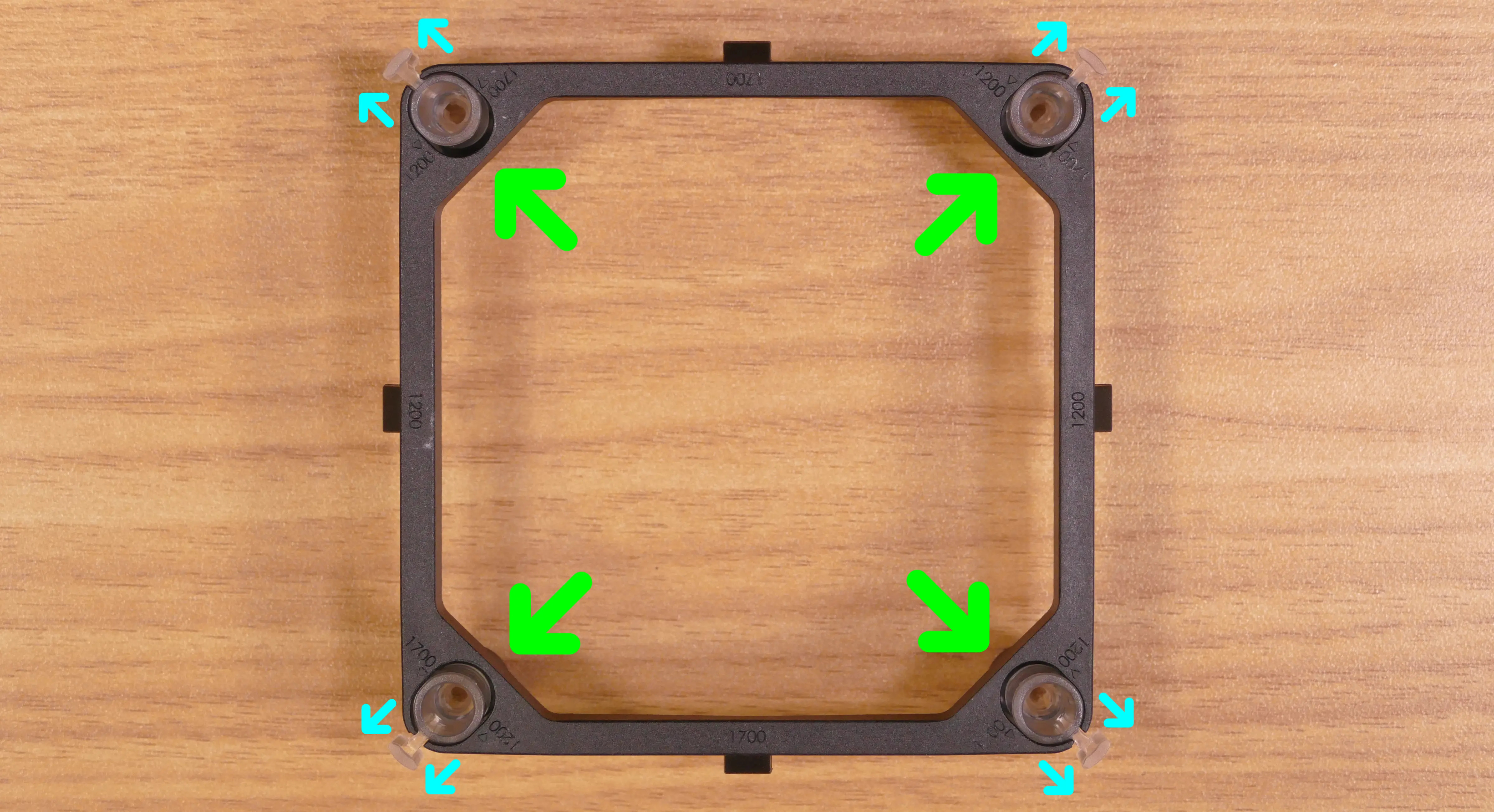
Steps to install the thermal paste/CPU cooler:
- Draw an
Xshape of thermal paste onto the CPU.

- Place the CPU cooler onto the CPU; while holding it in place, tighten the screws on the top and bottom of the vertical mounting bar to tighten the 90-degree clips onto the mounting bracket.
- The cooler should be oriented so the fan is on the right side (towards the front of the case).
- The 90-degree clips must be oriented inward to fasten onto the mounting bracket.
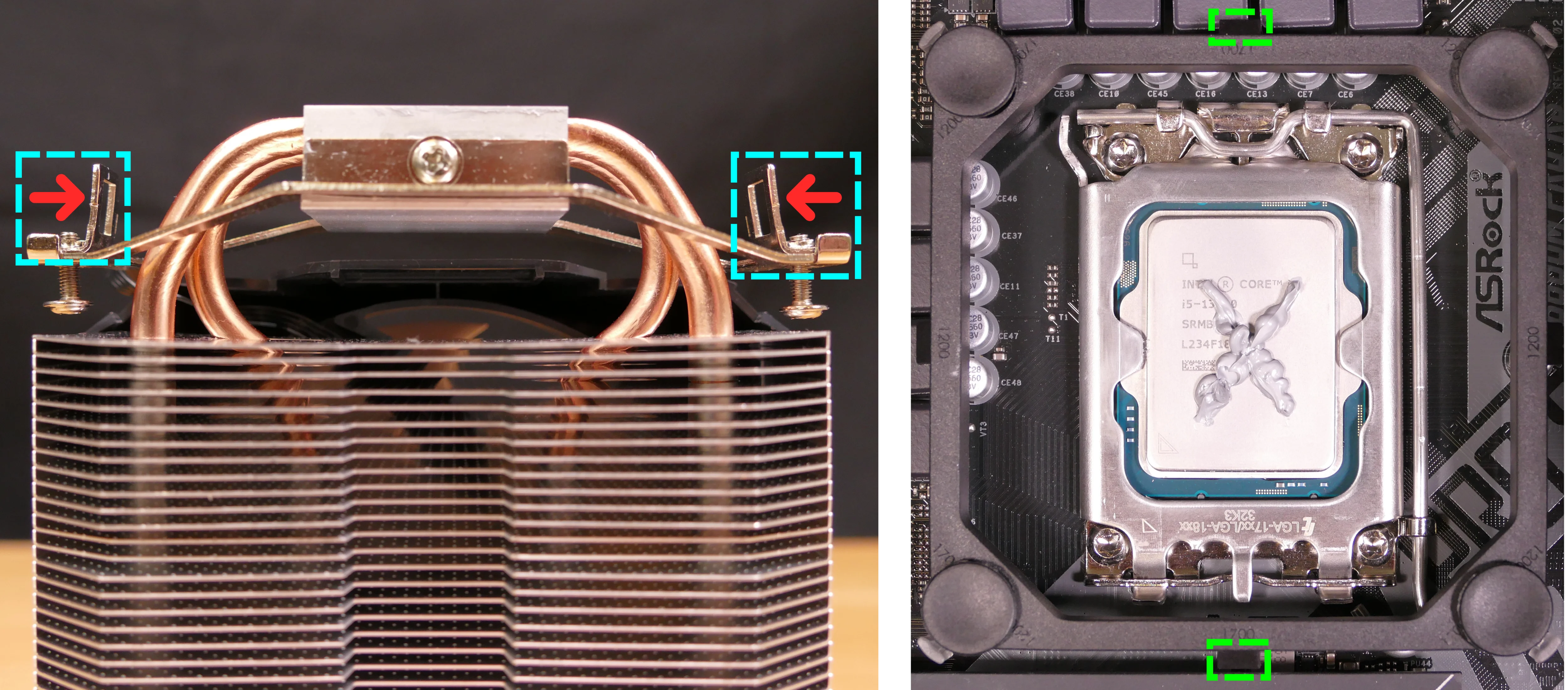
- Set the computer upright, then reinstall the cooler-mounted CPU fan (if necessary), RAM, CPU duct, GPU, side bracket, and top case.
Replacing the power supply:
The power supply unit (PSU) can be replaced with another unit of the same model. One possible preinstalled model is the Thermaltake Toughpower GX2 600W (80+ Gold).
The PSU is not modular, so all of its cabling will need to be unplugged and removed, then the new PSU's cabling will need to be run through the system and connected.
Tools required: Cross-head (Phillips) screwdriver
Time estimate: 45 minutes
Difficulty: Medium ●
Steps to replace the power supply:
- Follow the steps above to remove the top case, remove the side brace, and unplug the GPU.
- Locate and unplug all of the cables emanating from the power supply (shown below), including the following:
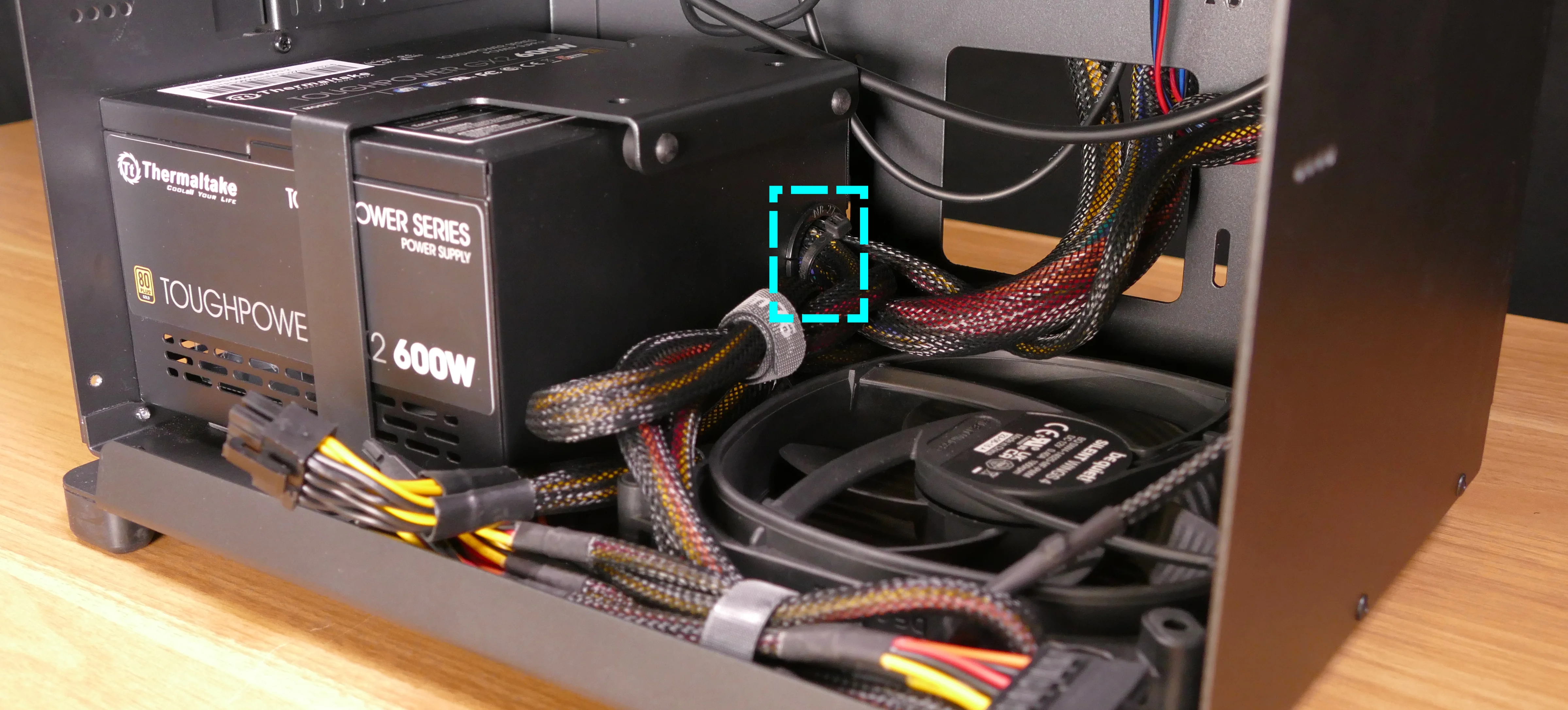
- The 8-pin CPU power cable labeled
ATX12V1near the top-left of the motherboard, highlighted green below. - The 24-pin motherboard power cable labeled
ATXPWR1on the right side of the motherboard, highlighted yellow below.
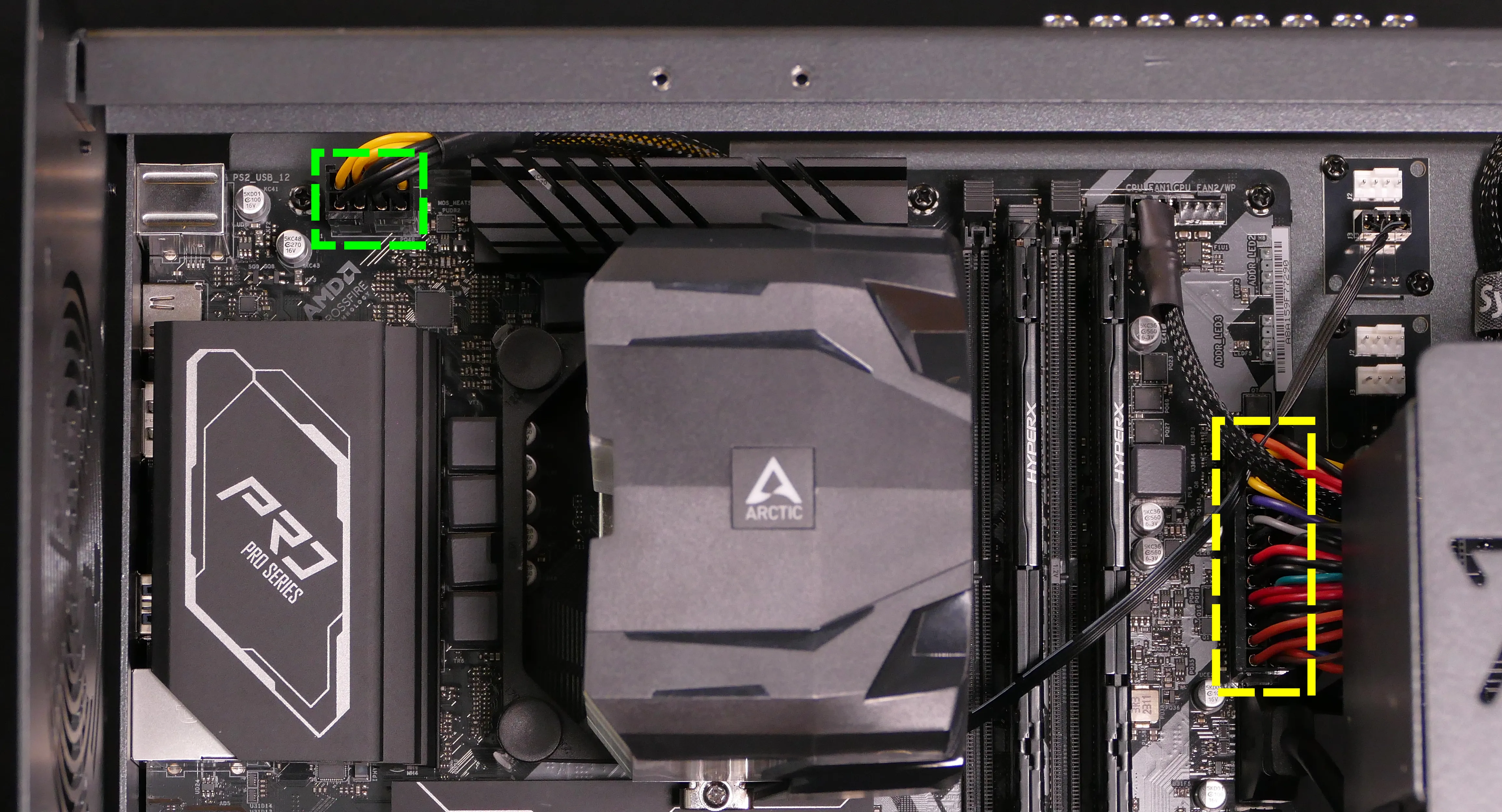
- The 4-pin Berg connector labeled
POWER1on the Thelio Io board.
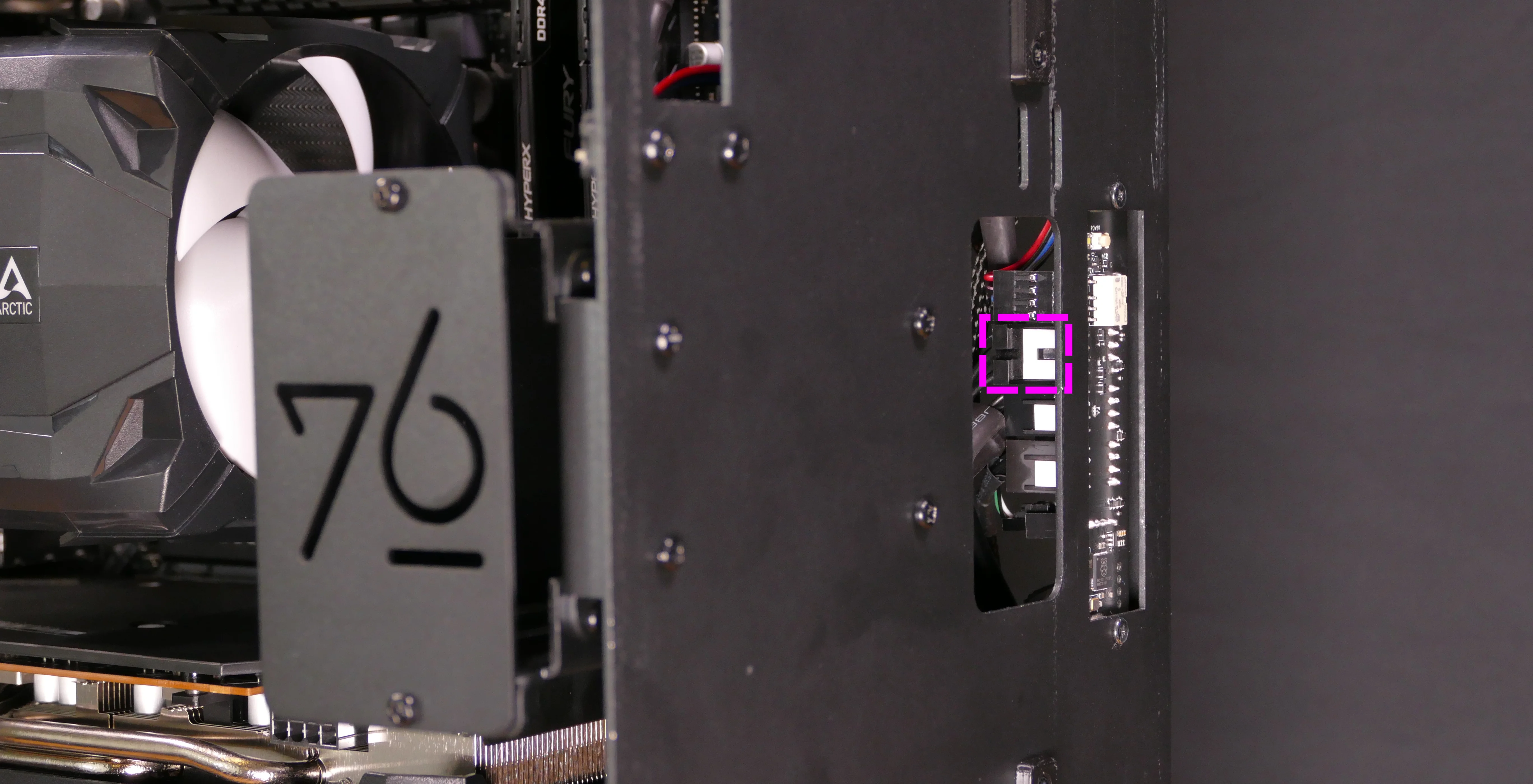
- The 4-pin Berg connector labeled
POWER0on the SATA backplane.
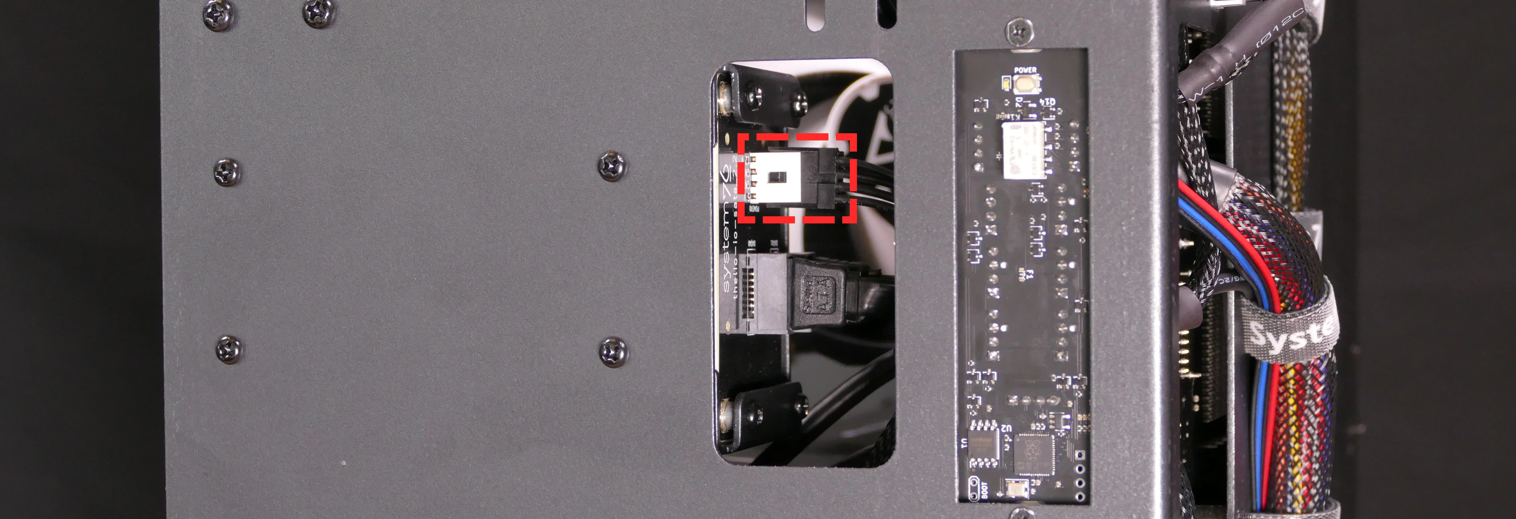
- Unscrew and remove the PSU bracket.
- One screw is located on the opposite side of the case.

- Unscrew the four screws holding the PSU in from the back of the case.

- Remove/replace the PSU.
- The replacement PSU should be installed with the fan facing the bottom of the case.
- Hold the PSU up to the screwholes in the back of the case while attaching it.
- Run the new PSU's wires through the system (securing them with velcro straps where necessary), then plug in the new PSU's wires into the motherboard (including the CPU plug), Thelio Io board, SATA backplane, and dedicated GPU (if installed).
Replacing the Thelio Io board:
Named after Jupiter's moon Io, the Thelio Io daughterboard handles the front power button and fan control. Thelio Spark B1-N2 uses Thelio Io version 2. If the Thelio Io board becomes defective, it can be replaced using the instructions below.
Tools required: Cross-head (Phillips) screwdriver
Time estimate: 30 minutes
Difficulty: High ●
Steps to replace the Thelio Io board:
- Follow the steps above to remove the top case.
- The CPU duct and side brace can optionally be removed to provide easier access to the cabling.
- Use the cutouts on the front right corner of the chassis to unplug all cabling from the Thelio Io board.
- The topmost connector requires pulling the white tab while unplugging.

- Unscrew the two screws holding the daughterboard on from the front of the chassis.

- Screw in the new Thelio Io board and reconnect the wiring.
Thelio Io wiring guide:

-
When wiring the Thelio Io board, refer to the port labels and the following guide.
FANOUT1/CPU FAN- to the top fan splitter (connecting to the CPU fans).FANOUT4/AUX FAN- to the bottom fan splitter (below the CPU fan splitter).FANOUT2/INTAKE FAN- to the bottom case fan.FANOUT3/GPU FAN- to the side brace fan splitter (disconnected by default).FANIN1/MOTHERBOARD FAN INPUT- to theCPU_FAN1header at the top right of the motherboard, highlighted cyan below.

POWER1/POWER INPUT- to the power supply.- The white plastic backing needs to be held away from the connector to unplug this cable from the Thelio Io board.
PFP1/FRONT PANEL- to the power button receptacle on the front panel.- On the Thelio Io board, the wire color order (from top to bottom) is red, black, blue, black.
- On the power button receptacle, the wire color order (from left to right) is red, black, blue, black.
PMB1/MOTHERBOARD- to thePANEL1header at the bottom right of the motherboard, highlighted green below.- On the Thelio Io board, the wire color order (from top to bottom) is red, black, blue, black.
- On the motherboard, the wire color order (from left to right) is red, black, blue, black.
USB- to theUSB_3_4header on the bottom edge of the motherboard, highlighted yellow below.- A small clip needs to be held down to unplug this cable from the Thelio Io board.
- This port can alternatively be connected to the
USB_5_6header if theUSB_3_4header is connected to the wireless card.

Replacing the SATA backplane:
The SATA backplane provides two 2.5" SATA data and power connectors for the 2.5" drive cage. The part number and version for the SATA backplane is thelio-io-sata_2.2.
Tools required: Cross-head (Phillips) screwdriver
Time estimate: 30 minutes
Difficulty: Medium ●
Steps to replace the SATA backplane:
- Follow the steps above to remove the top case, then remove the 2.5" drive cage cover and all 2.5" SATA drives.
- The CPU duct can optionally be removed to provide easier access to the cabling.
- Use the cutouts on the front right corner of the chassis to unplug the 4-pin Berg power connector (highlighted cyan below) and the two SATA data cables (highlighted green below) from the SATA backplane.
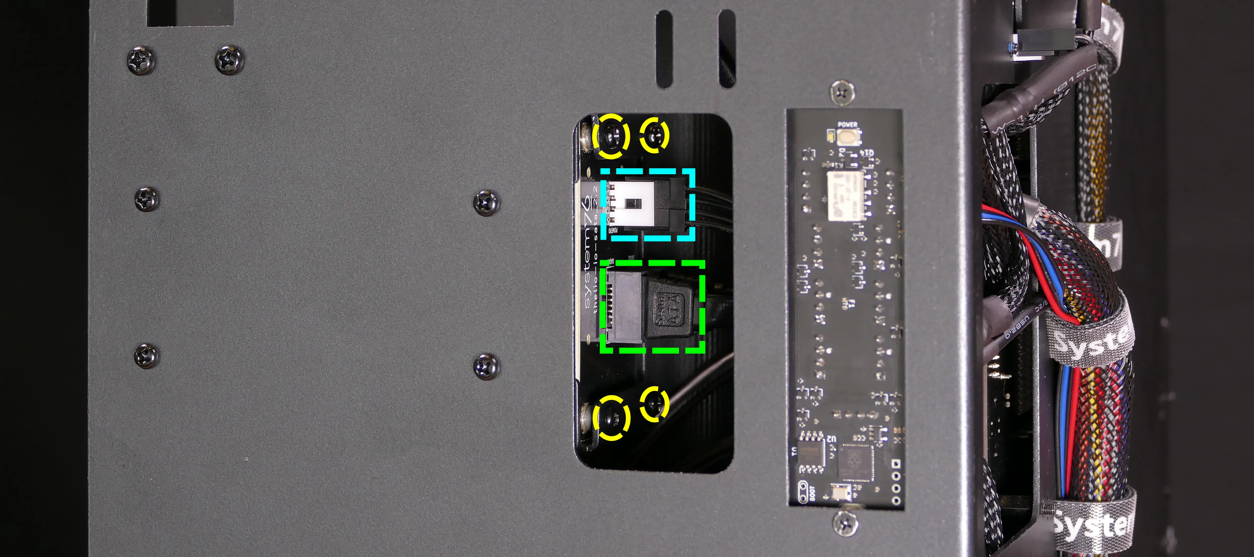
- Unscrew the four screws holding the drive cage onto the chassis (highlighted red above), then remove the drive cage from the chassis.
- This step is optional if you can remove the four SATA backplane screws (highlighted yellow above and below) from the drive cage without removing it from the chassis. The Thelio Io cabling partially obstructs the screws, so removing the cage is suggested.

- Unscrew the four SATA backplane screws from the drive cage, then push the SATA backplane out through the front of the drive cage.

- Place the new SATA backplane into the drive cage and secure it with the four SATA backplane screws, then reinstall the drive cage (if necessary).
- Plug the 4-pin Berg power connector and SATA data cables into the SATA backplane.
- The order of the SATA data cables shouldn't matter as long as your operating system and software is configured to address disks by UUID (e.g.
/dev/disk/by-id/...) instead of by letter (e.g./dev/sd_). - By default, the
DATA1port connects to the innermost SATA connector on the motherboard, and theDATA0port connects to the outermost SATA connector on the motherboard.
- The order of the SATA data cables shouldn't matter as long as your operating system and software is configured to address disks by UUID (e.g.
- Reinstall the CPU shroud (if necessary), any 2.5" drives that were removed, the 2.5" drive cage cover, and the top case.
Replacing the top I/O:
Thelio Spark B1-N2 includes a top I/O module providing audio and USB ports. This module's part number is MYS7523 Rev. 4.0.
If the top ports are damanged or become defective, they can be replaced using the steps below.
Tools required: Cross-head (Phillips) screwdriver
Time estimate: 30 minutes
Difficulty: Medium ●
Steps to replace the top I/O:
- Follow the steps above to remove the top case and remove the CPU duct.
- You can optionally remove the side brace for easier access to the wiring.
- Unplug the
HD_AUDIO1header at the bottom-left corner of the motherboard, below the wireless card.

- Unplug the
F_USB3_5_6header (highlighted cyan below) andF_USB3_TC_1header (highlighted green below) along the right edge of the motherboard, between the RAM and the 2.5" drive cage.

- Unscrew the two front screws holding the top I/O board onto the chassis.

- Remove the top I/O board from the system.
- Insert the new top I/O board into the system and screw it into place.
- Reconnect the audio and USB headers.
- Replace the side brace (if necessary), CPU shroud, and top case.
Troubleshooting the power button:
If the front power button doesn't power the machine on or doesn't light up when the system is powered on, try the following troubleshooting steps:
- Ensure the system powers on normally using the internal power button.
- Reseat the front power button to ensure it's making proper contact.
- Check the wiring for the front power button.
- Replace the front power button, if necessary.
Tools required: Cross-head (Phillips) screwdriver (optional)
Time estimate: 20 minutes
Difficulty: Medium ●
Steps to power the machine on using the internal power button:
- Follow the steps above to remove the top case.
- Ensure the system is plugged into power, and the power supply switch is in the 1 (On) position.
- Push the small button labeled
POWERon the Thelio Io board.- The white LED to the left of the button lights up to indicate when the system is powered on (and pulses when the system is suspended).

- If the Thelio Io
POWERbutton powers the machine on and the LED lights up, then the issue is either the front power button or its connection to the Thelio Io board. Check the front power button wiring. - If the Thelio Io
POWERbutton and/or LED does not work, then the issue is either the Thelio Io board or its connection to the motherboard. Check the wiring between the Thelio Io board and the motherboard.
Steps to check the front power button wiring:
- Follow the steps above to remove the top case.
- On the back of the power button, the four pins should be connected to the four-wire connector as follows:

- On the front power button receptacle, the four-pin connector should have the red wire on the left and the black wire on the right (when viewed from the back of the computer.)
- If necessary, you can remove the 2.5" drive cage for easier access to the power button receptacle's connector.

- The front power button receptacle should plug into the
PFP1port on the Thelio Io board, with the red wire on the top (see the Thelio Io wiring guide.)
Steps to replace the power button:
- Follow the steps above to remove the top case.
- Follow the instructions in the Replace the Thelio Power Button support article.
