Thelio Spark (Parts & Repairs)
Many components in your Thelio Spark can be upgraded or replaced as necessary. This page uses photos of the the B1-N2 revision, which indicates:
- B1: The first Intel motherboard model used in Thelio Spark.
- N2: Based on the second revision of the nebula36 chassis.
Minor case details may vary based on the production date of the unit, but screw counts, general component locations, and other details should remain the same unless otherwise noted.
Power the machine off, switch off the power supply, and unplug all peripherals before working with any internal components. Then, follow these step-by-step guides for instructions:
- Replacing the front accent strip
- Removing the top case
- Adding/removing 2.5“ storage drives
- Removing the side brace
- Replacing the bottom case fan
- Removing the CPU duct
- Replacing the GPU
- Replacing the CMOS battery
- Replacing the wireless card
- Replacing the RAM
- Replacing the M.2 drives
- Replacing the CPU fans
- Replacing the CPU cooler/thermal paste and CPU
- Replacing the power supply
- Replacing the Thelio Io board
- Replacing the SATA backplane
- Replacing the top I/O
- Troubleshooting the power button
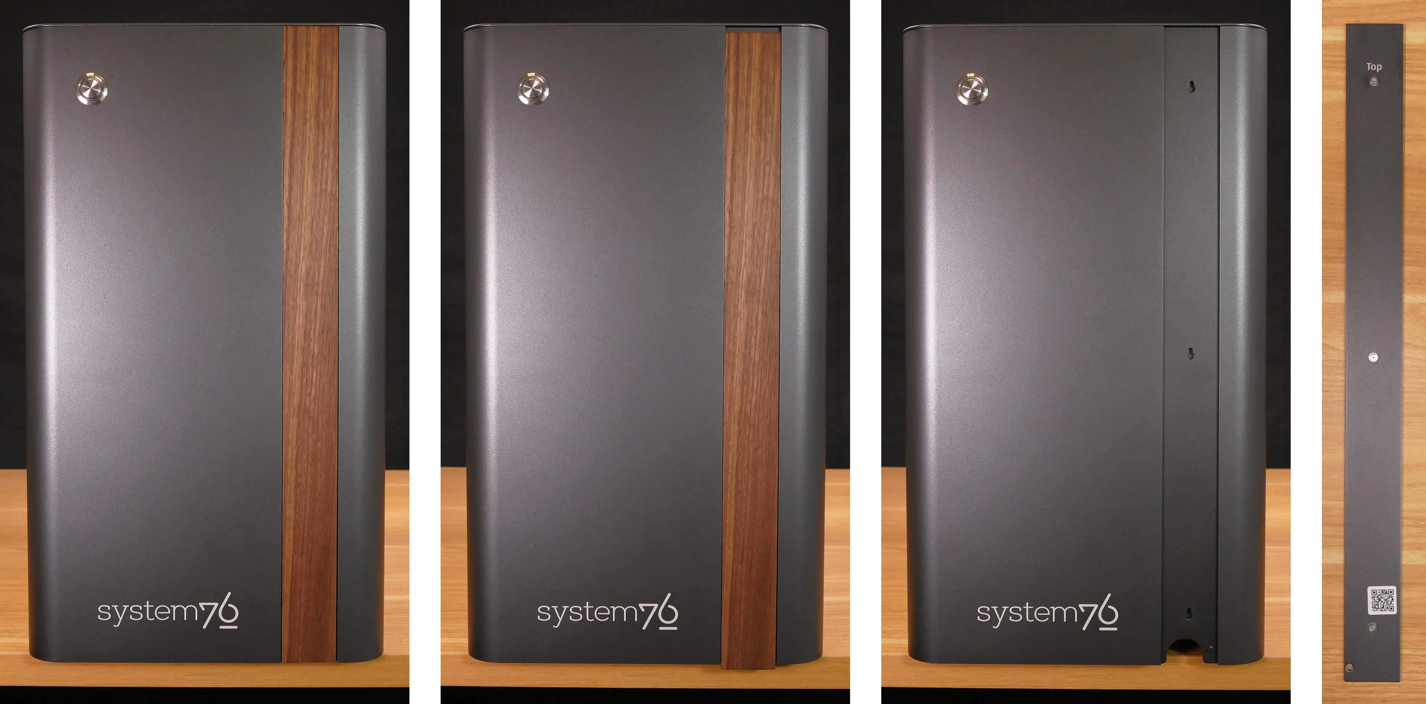
Replacing the front accent strip:
Thelio Spark includes a customizable accent panel on the front of the case, which can be swapped to change the case’s look and feel. The instructions for swapping the accent are also available in video form.
Tools required: None
Time estimate: 30 seconds
Difficulty: Easy ●
Steps to replace the front accent strip:
- Place the Thelio on the edge of the desk so the front side is hanging off of the desk.
- The Thelio can alternatively be lifted or tilted so the front of the computer is hovering above the desk.
- Slide the accent strip down to unlock it.
- The accent can be gripped at the bottom edge.
- Pull the accent strip off of the case, starting with the bottom edge.
- Place the new accent strip onto the front of the case and slide it up to lock it into place.
Removing the top case:
The top case can be removed to access the internal components.
Tools required: Cross-head (Phillips) screwdriver (optional)
Time estimate: 2 minutes
Difficulty: Easy ●
Steps to remove the top case:
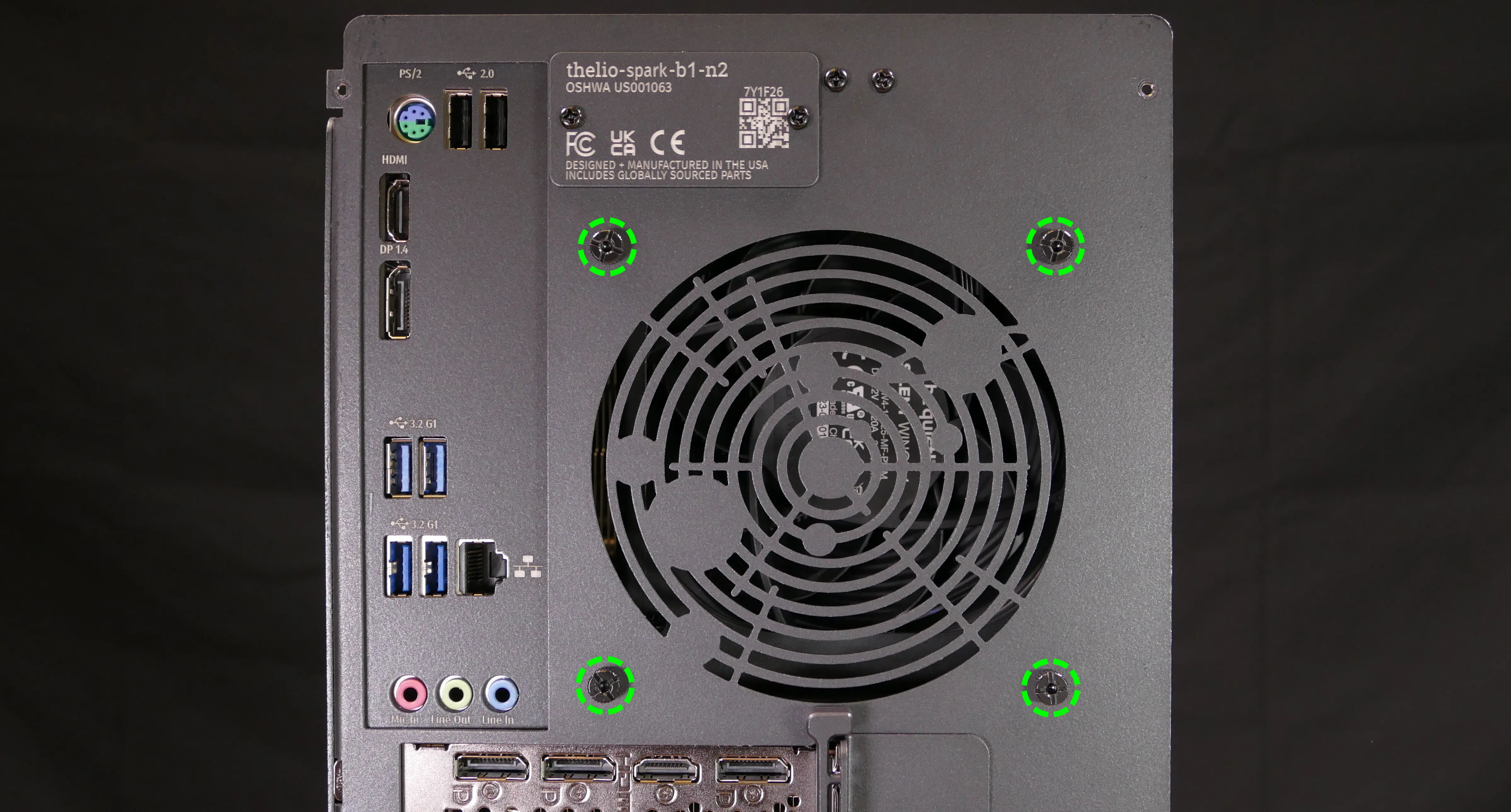
- Remove the four outer screws holding the top case onto the machine.
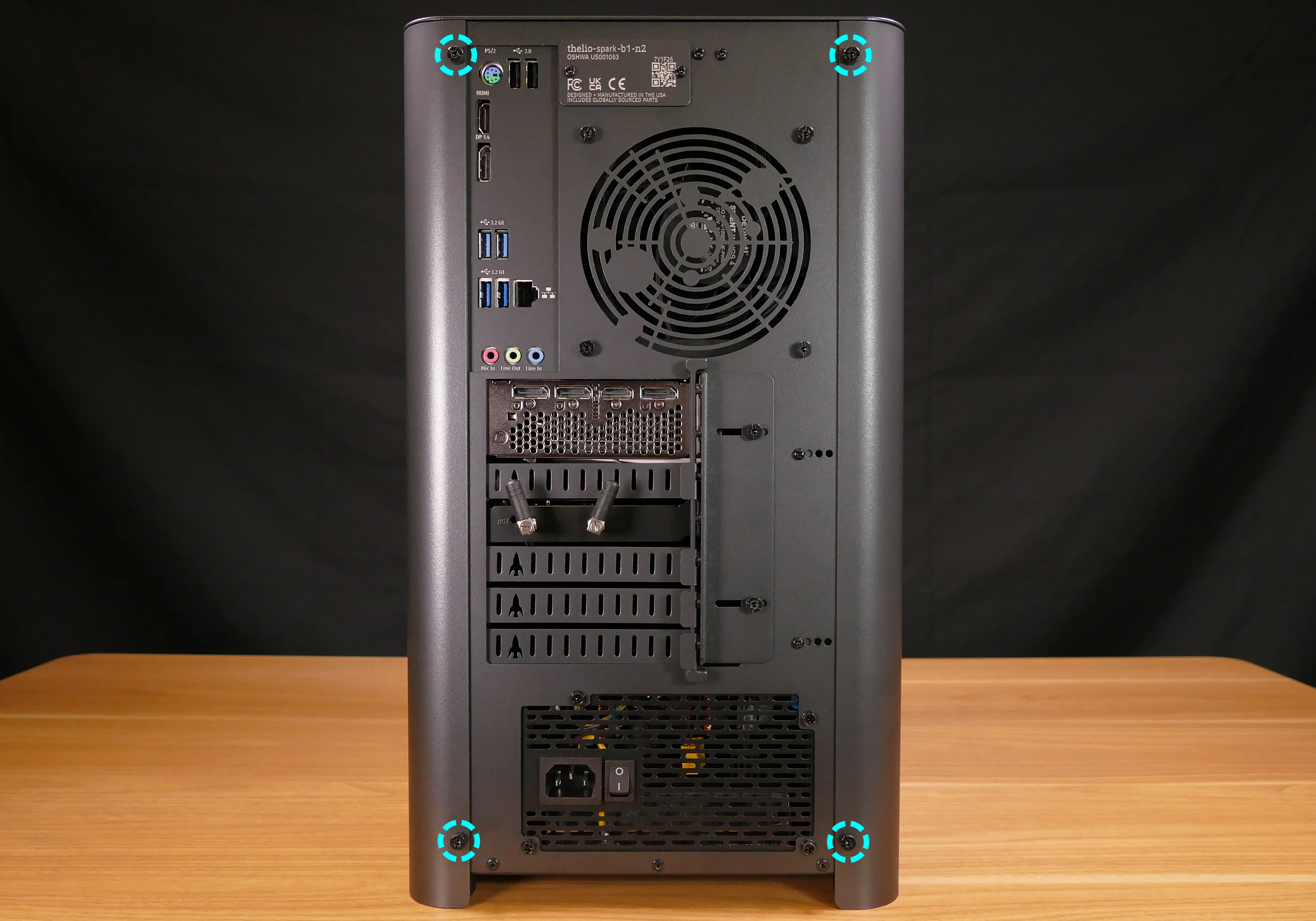
- Slide the top case up and off of the machine.
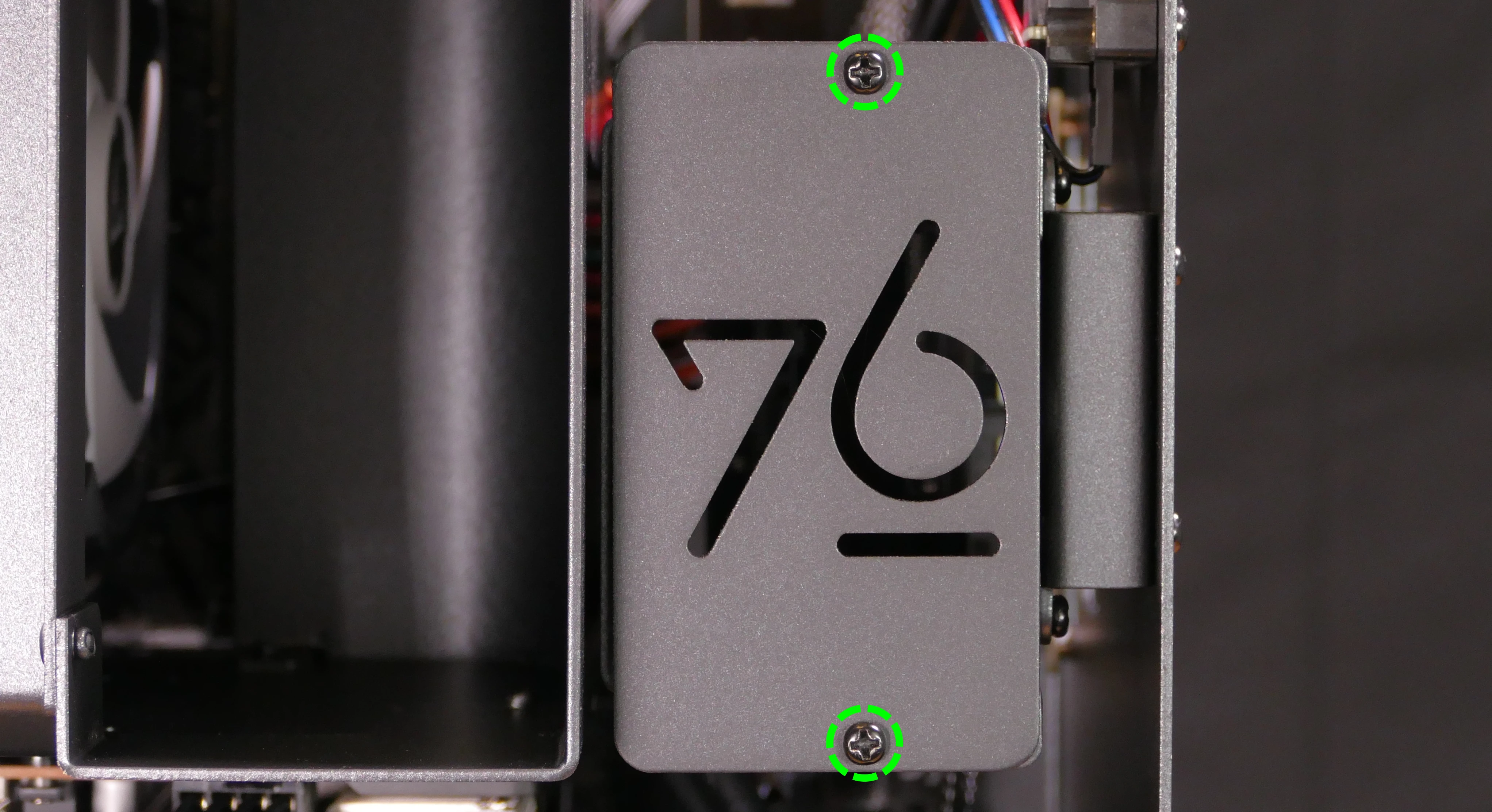
Adding/removing 2.5“ storage drives:
Thelio Spark B1-N2 supports up to two 2.5“ SATA III drives.
Tools required: Cross-head (Phillips) screwdriver
Time estimate: 7 minutes
Difficulty: Easy ●
Steps to add/remove 2.5“ storage drives:
- Follow the steps above to remove the top case.
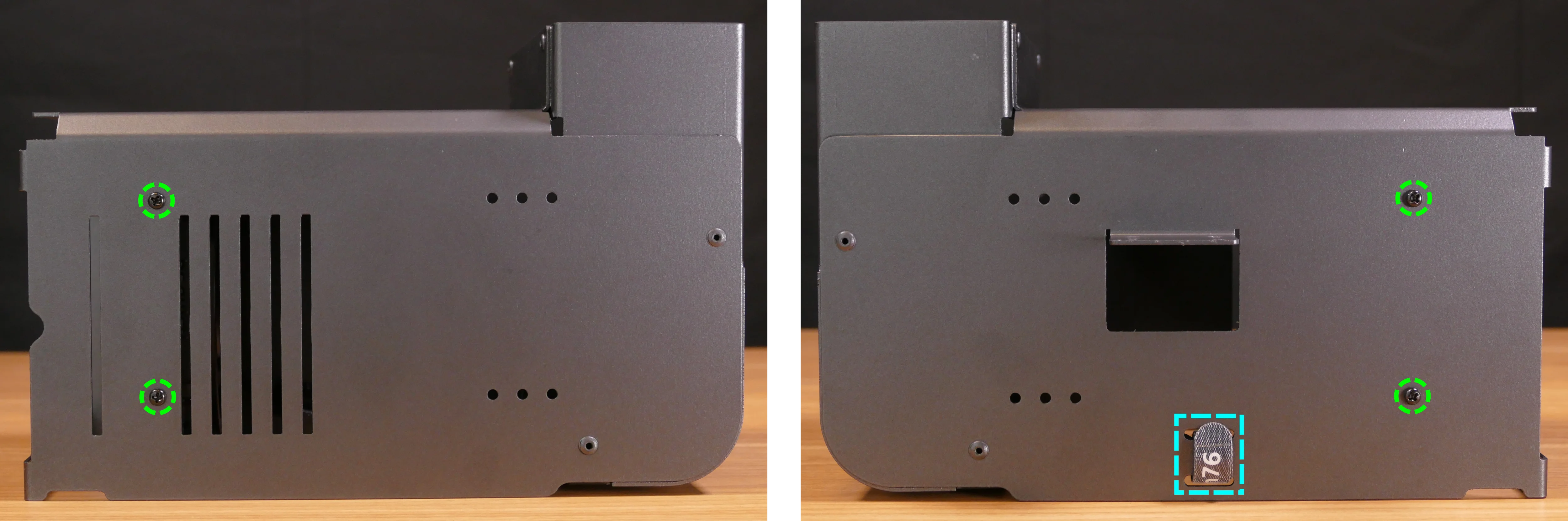
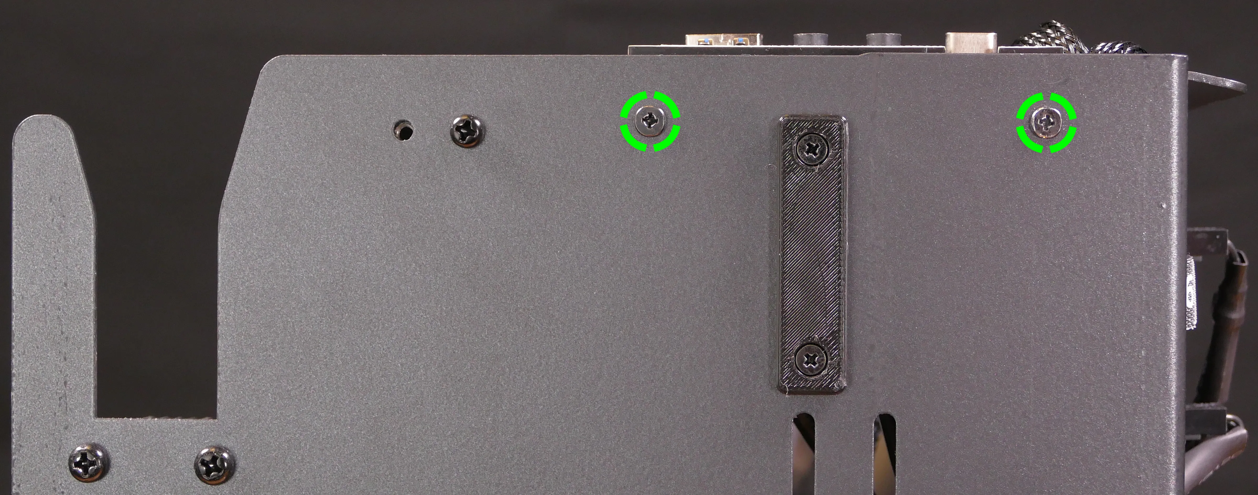
- Unscrew the two screws securing the drive bay’s cover, highlighted green below.
- If you are adding a new drive, pop out the black plastic ring on the top crossbar and slide out four screws (per drive).
- Insert four screws into each 2.5“ storage drive you wish to install.
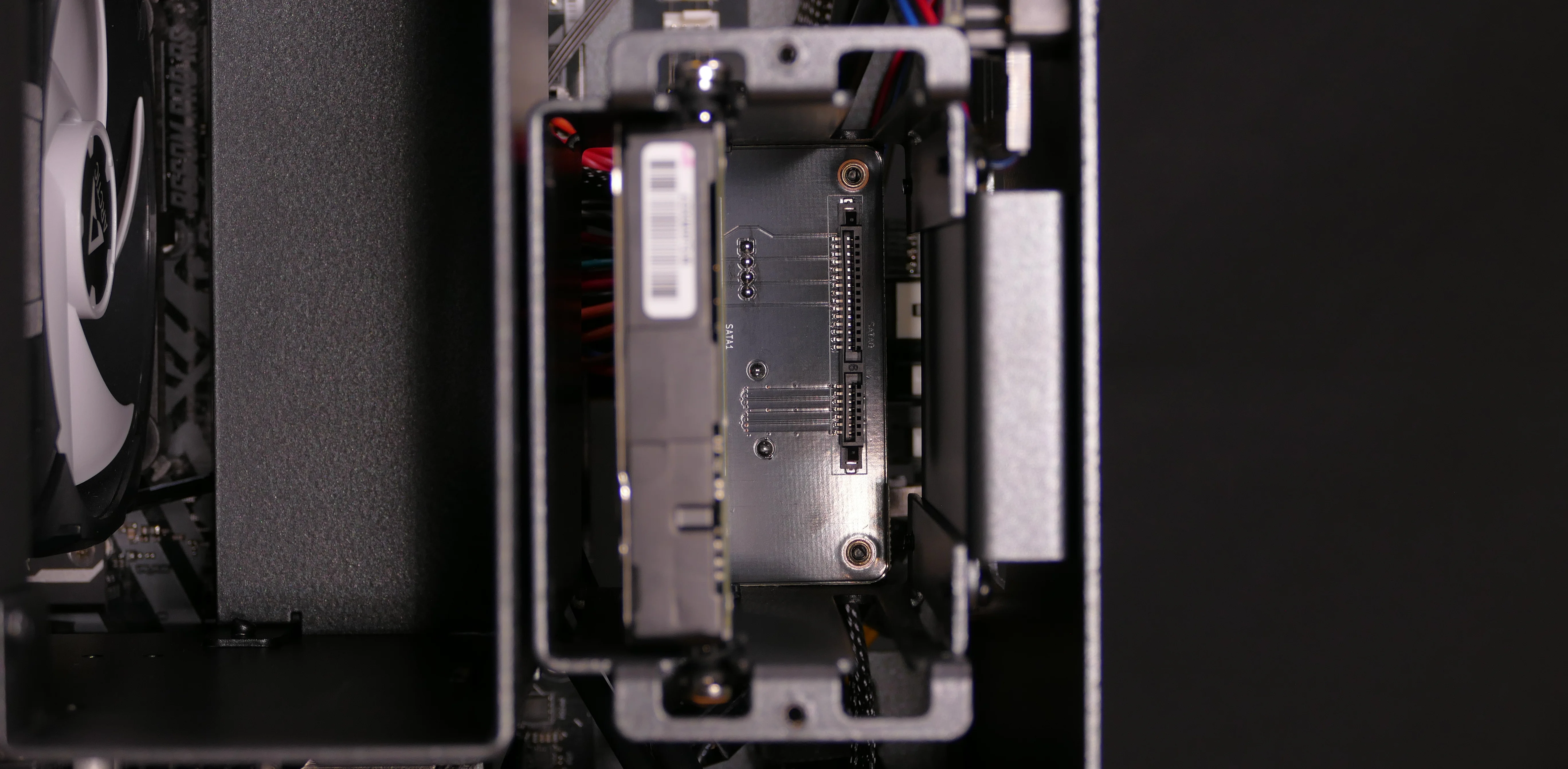
- Slide each 2.5“ drive into one of the slots leading to the SATA backplane.
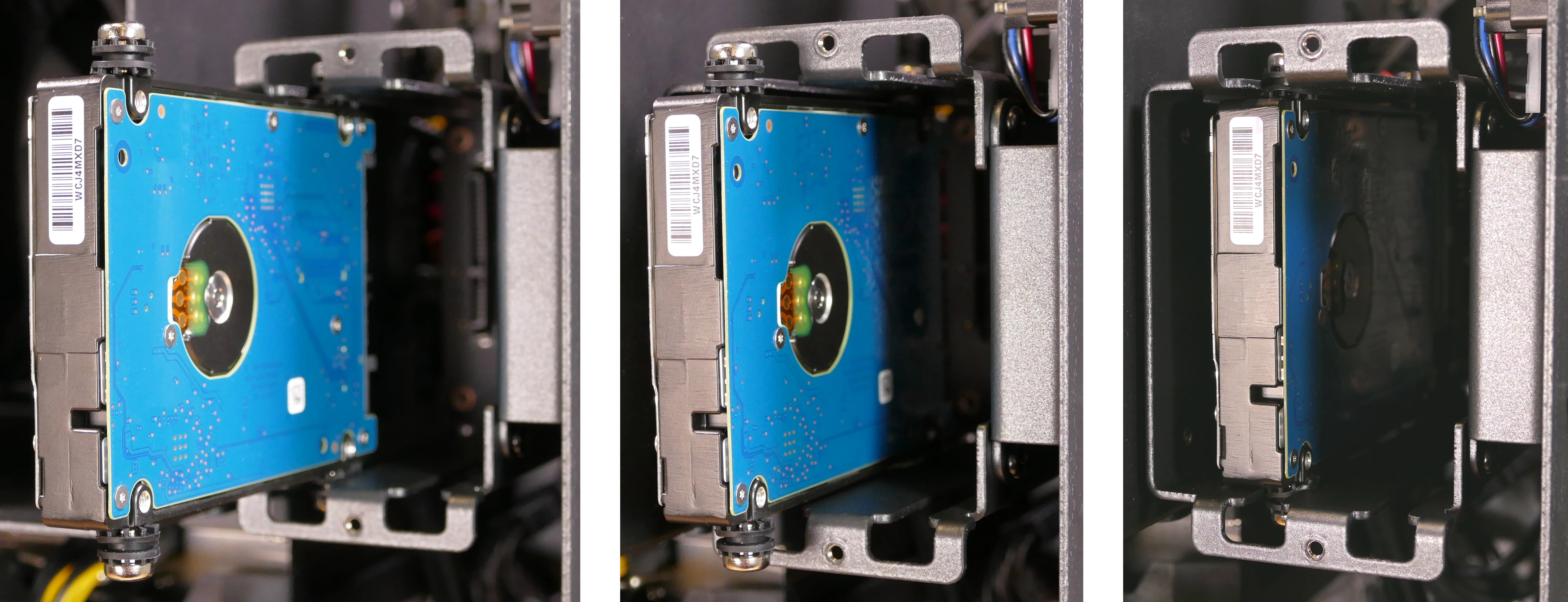
- Replace the black plastic screw ring and the 2.5“ drive bay cover.
Removing the side brace:
The side brace provides a mounting point for the GPU brace finger, which helps keep GPUs or other PCI Express cards in place during shipping. It also provides mounting points for two 120mm fans, which are not offered as part of Thelio Spark but can optionally be installed as an aftermarket upgrade.
The GPU brace finger is only required during shipping. The system can be run without this part if it does not fit an upgraded GPU.
Tools required: Cross-head (Phillips) screwdriver
Time estimate: 15 minutes
Difficulty: Easy ●
Steps to remove the side brace:
- Follow the steps above to remove the top case.
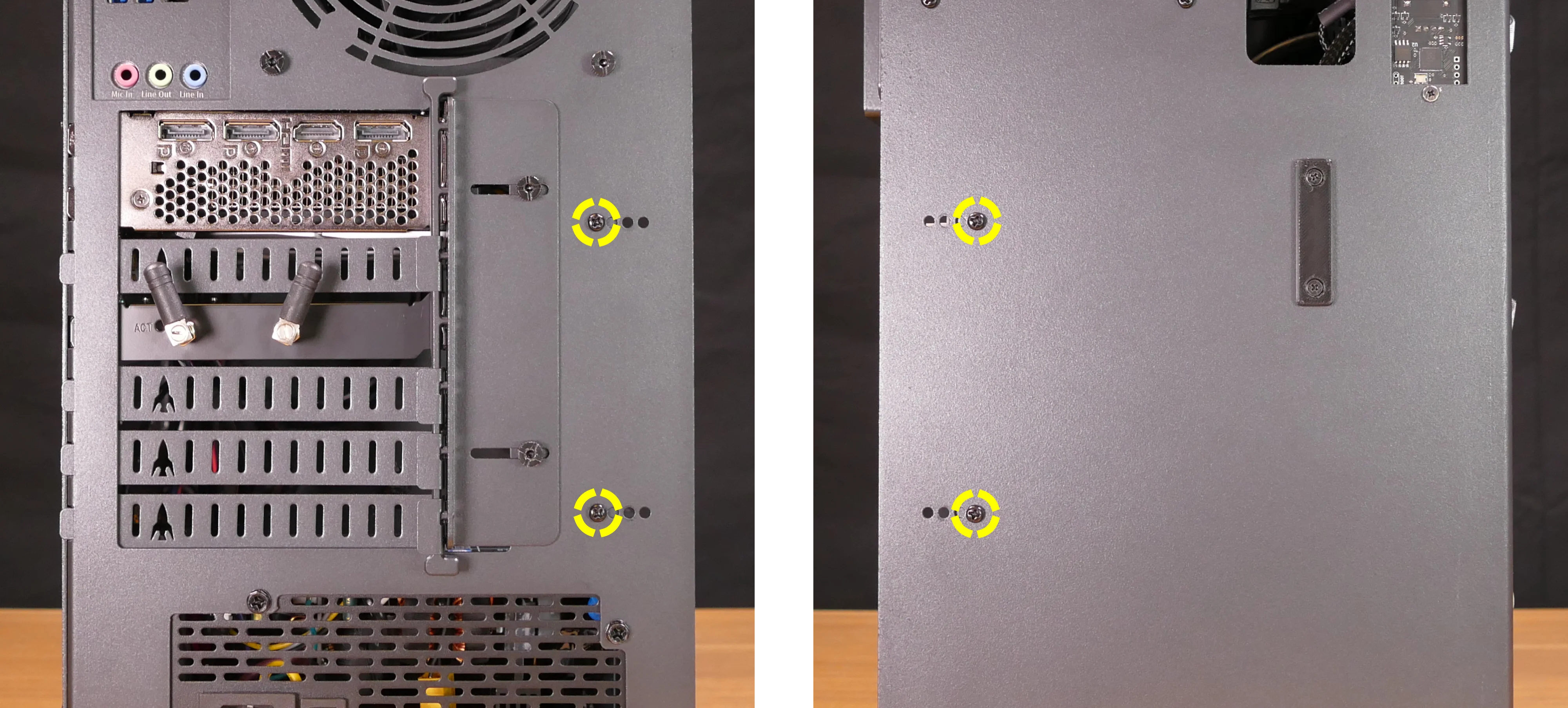
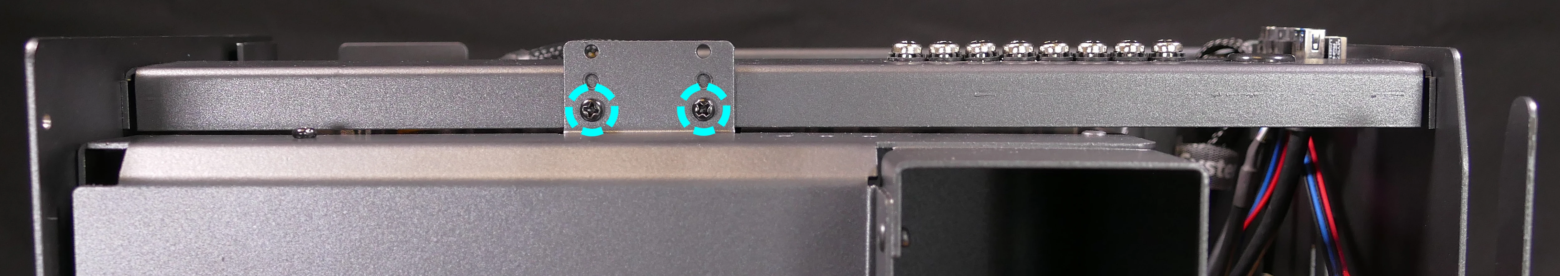
- Unscrew the four screws holding the side bracket in place (two on the front of the case, two on the back.)
- Pull the side brace out of the chassis. Unplug the side fan connector from the splitter board on the right side, if connected.
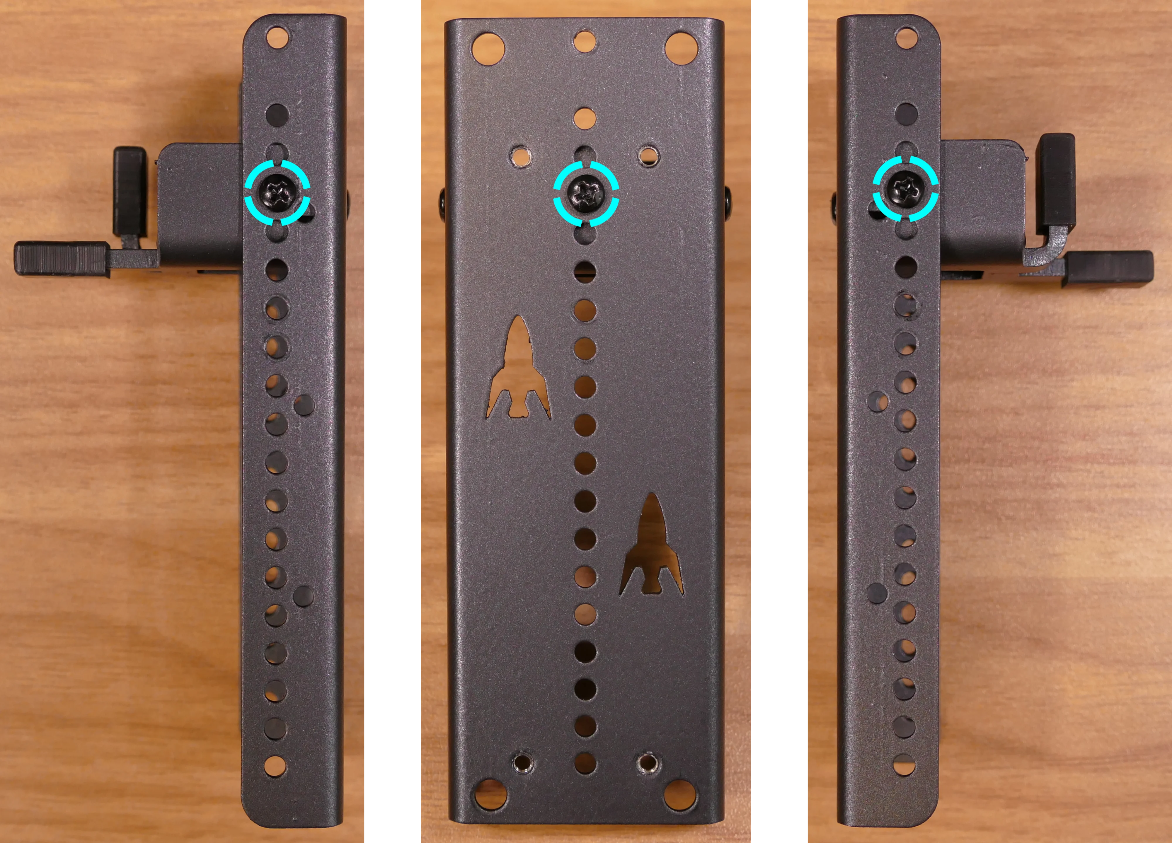
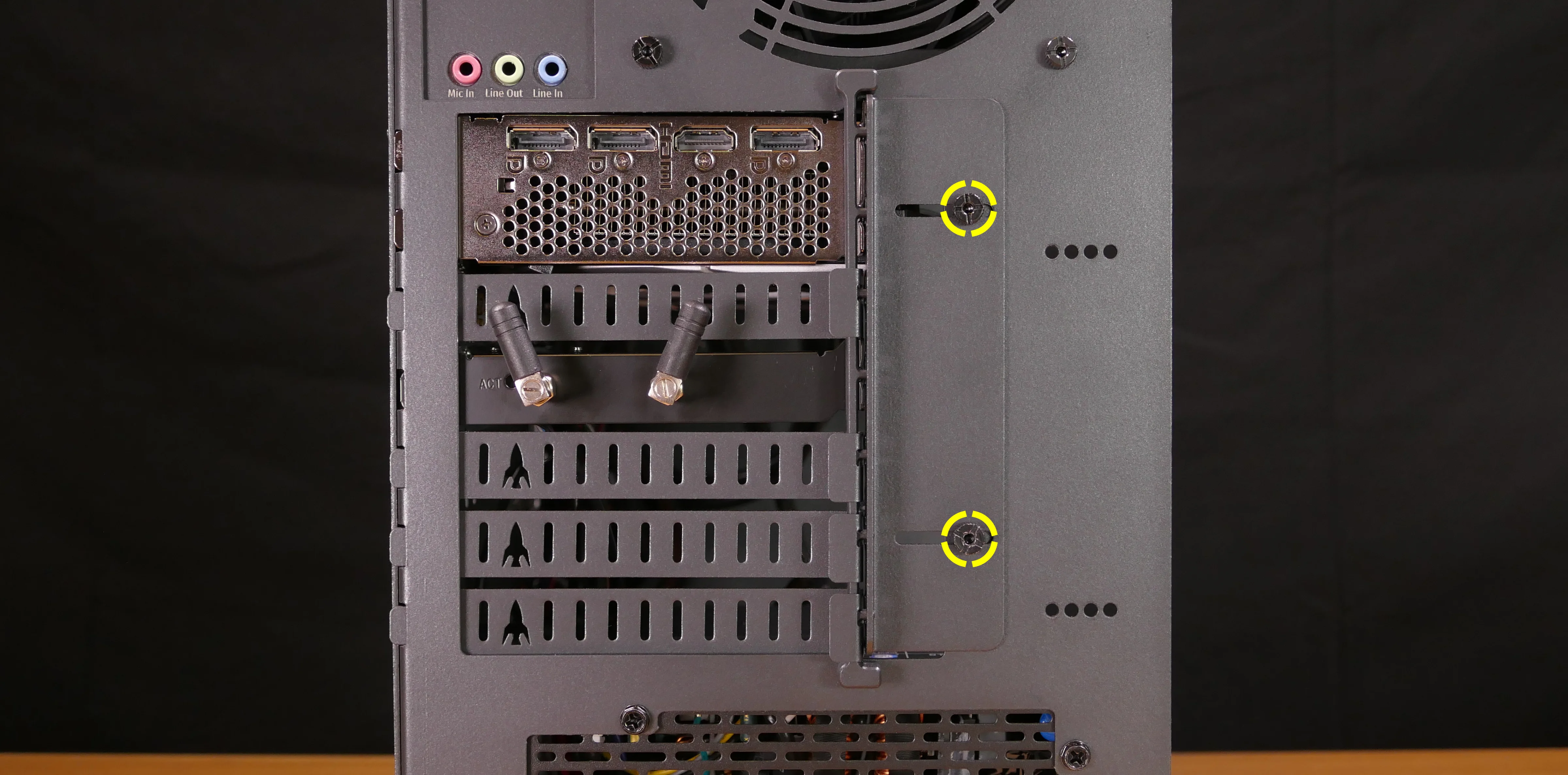
Steps to adjust the GPU brace finger:
- Follow the steps above to remove the top case and remove the side brace.
- To adjust the GPU brace finger’s horizontal position, unscrew the four corner screws (highlighted green below), move the GPU brace finger’s mounting bar, and reattach it in the desired position.
- The center vertical adjustment screw (highlighted cyan below) may also need to be removed or loosened.
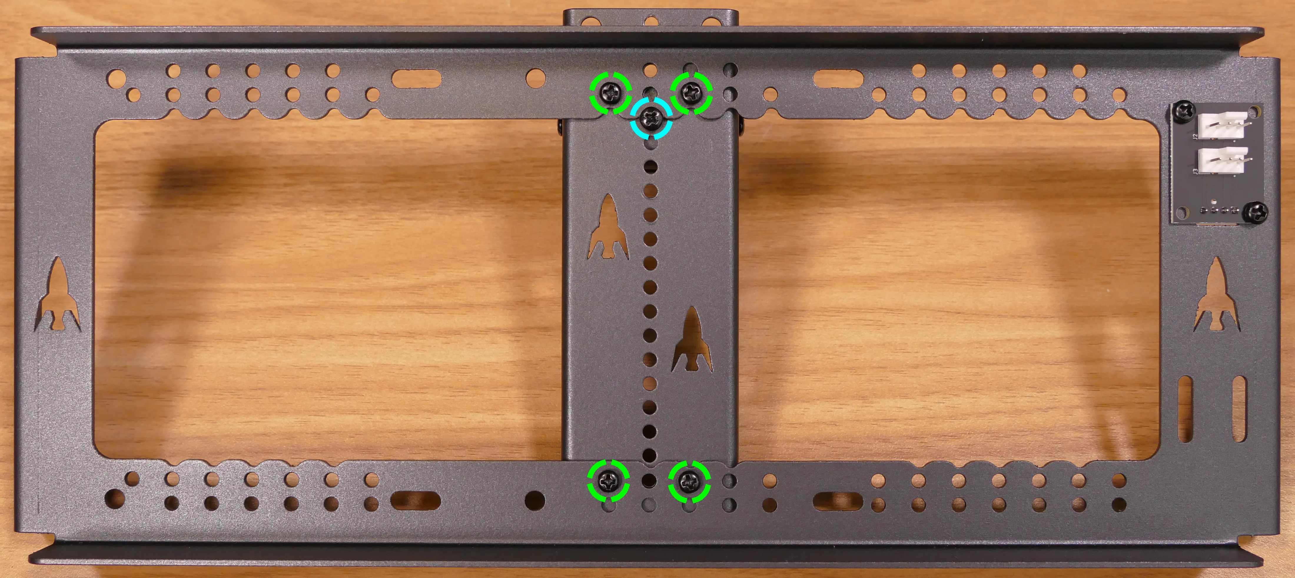
- To adjust the GPU brace finger’s vertical position, unscrew the three vertical adjustment screws, move the GPU brace finger, and reattach it in the desired position.
Replacing the bottom case fan:
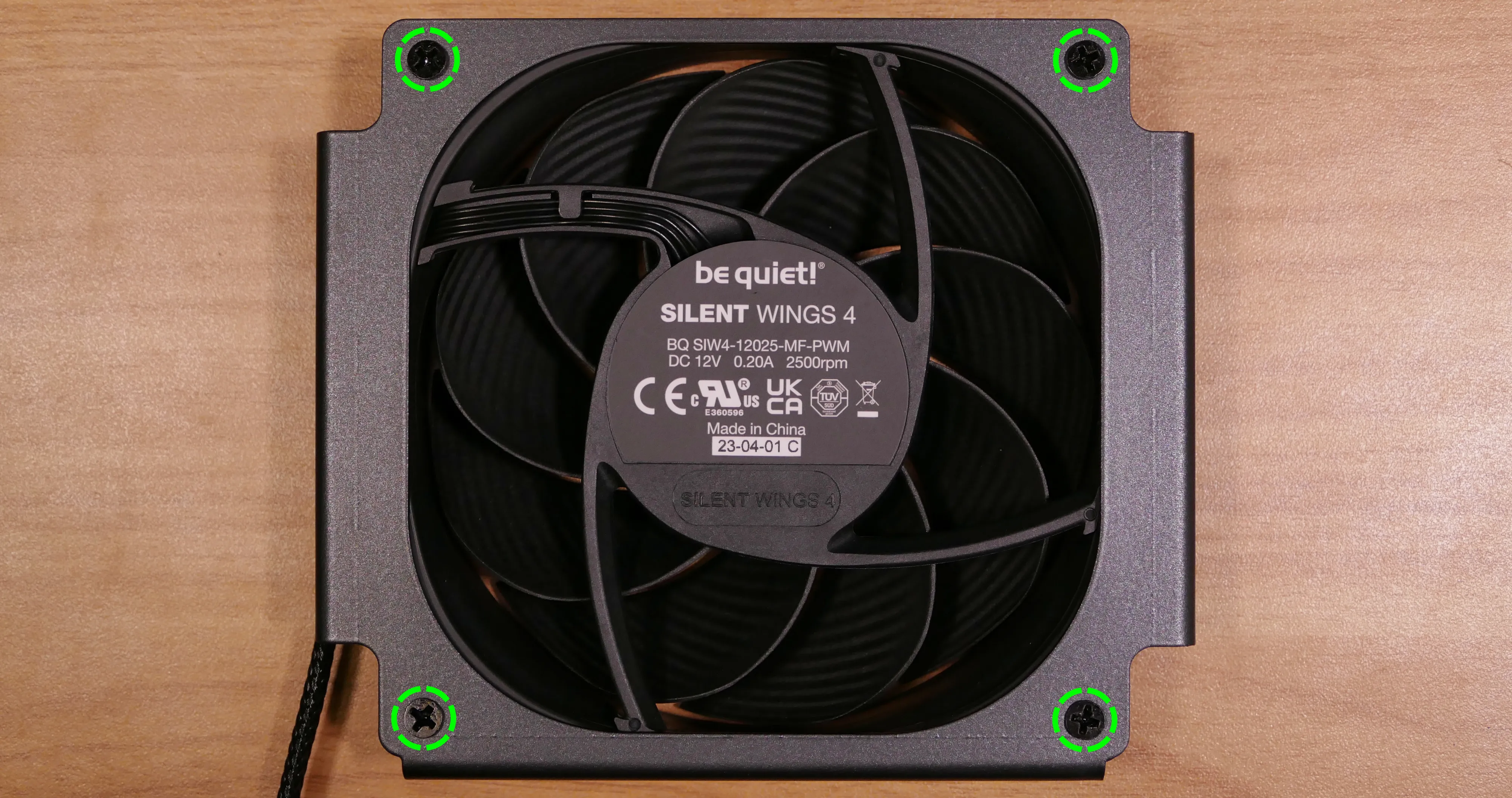
Thelio Spark B1-N2 has one case-mounted intake fan on the bottom of the chassis. The fan is a 140mm Be Quiet! Silent Wings 4 (model number BQ SIW4-14025-MF-PWM).
Tools required: Cross-head (Phillips) screwdriver
Time estimate: 20 minutes
Difficulty: Medium ●
Steps to replace the bottom case fan:
- Follow the steps above to remove the top case.
- The side brace can optionally be removed to provide easier access to the fan and its cabling.
- Unplug the fan’s cable from the Thelio Io daughterboard.
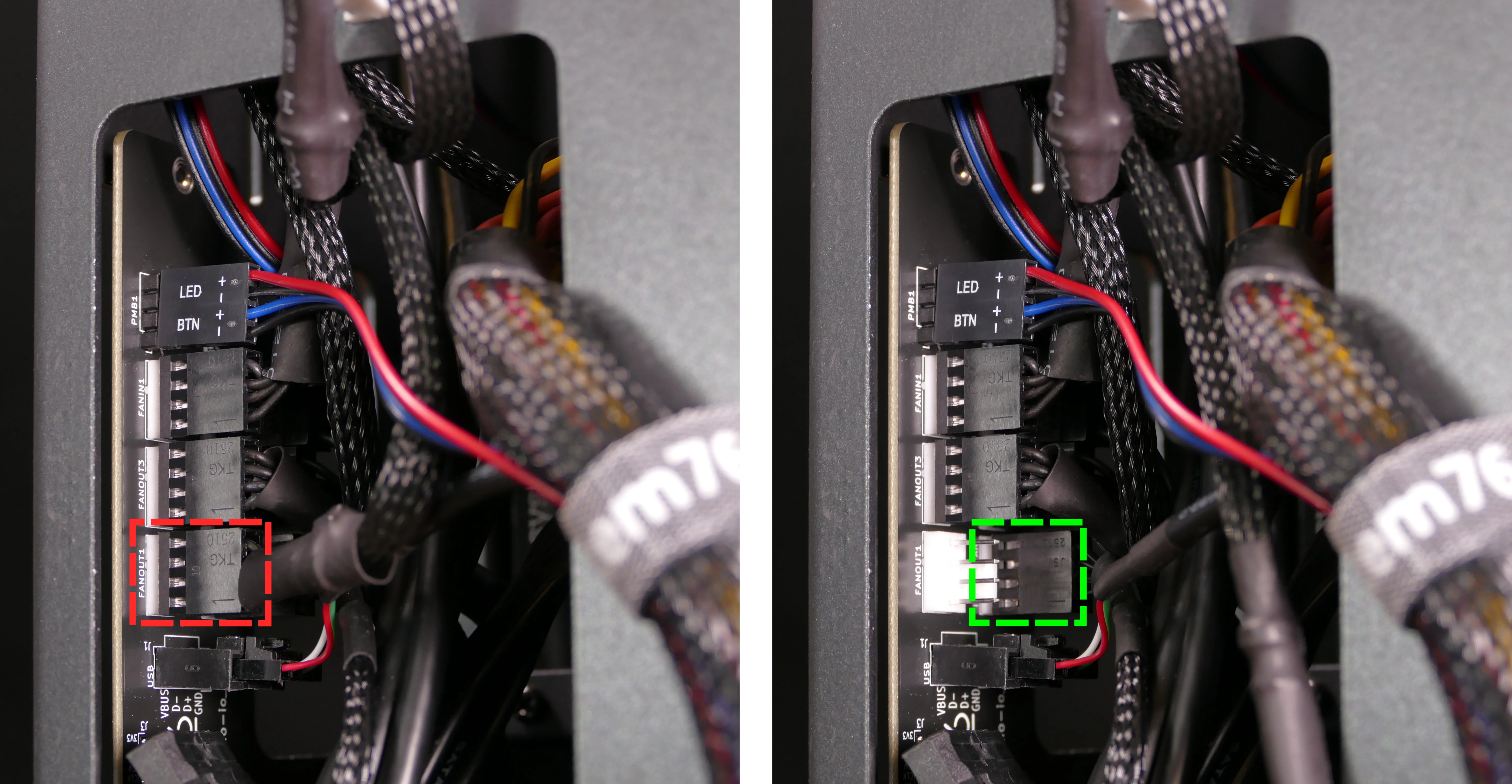
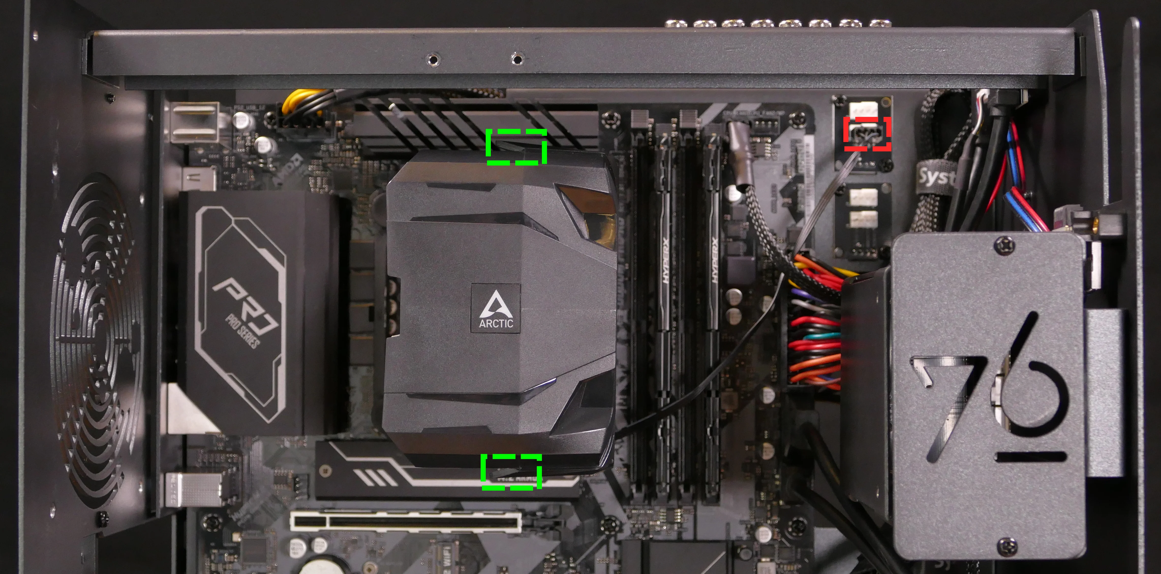
- The bottom case fan plugs into the
INTAKE FANport on the Thelio Io board. - When viewed from the access cutout on the side of the case, this connector is second from the bottom, next to the
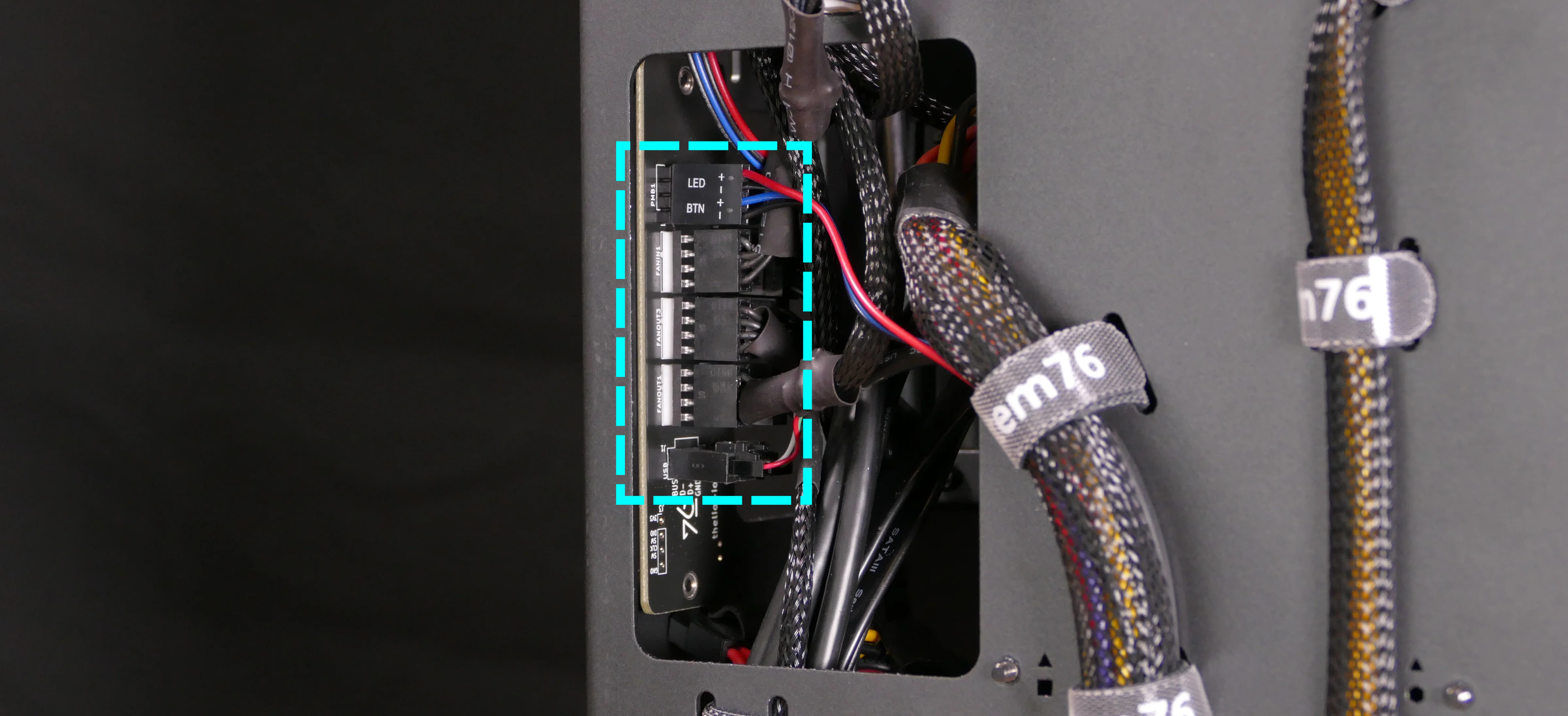
FANOUT1port.- The
FANOUT1port (highlighted red below) can be unplugged for easier access to theINTAKE FANport (highlighted green below).
- The
- The bottom case fan plugs into the
- Unscrew the four fan screws from the bottom of the machine.
- To avoid damaging other components, place the machine on its front side when working with the bottom surface.
- A soft surface such as a towel can optionally be used to protect the work surface and the machine.
- Remove the old fan from the case.
- When installing the fan, mount the components in the following order:
- Chassis
- Dust filter
- Acrylic spacer
- Fan
- The new fan’s cable should be oriented towards the front-right corner of the case.
- The cable runs along the inner corner of the case, passing through the bottom two velcro straps twice (left through both, then right through both) and the higher two velcro straps once.
Removing the CPU duct:
The CPU duct guides airflow through the CPU cooler. It covers the CPU and partially obstructs the RAM slots and top PCIe slot.
Tools required: Cross-head (Phillips) screwdriver
Time estimate: 7 minutes
Difficulty: Easy ●
Steps to remove the CPU duct:
- Follow the steps above to remove the top case and remove the side brace.
- The GPU can also optionally be removed to provide more room for working with the components.
- Unplug the braided connector for the duct-mounted CPU fan from the top splitter board in the front corner of the machine.
- The splitter board provides the same signal to both ports, so it doesn’t matter which fan is plugged into which port.
- Unscrew the four back thumbscrews and two top crossbar screws holding the CPU duct in place.
- Pull the CPU duct away from the machine.
Replacing the GPU:
Thelio Spark ships with an optional dedicated GPU in the PCIe 4.0 x16 slot (top slot). Factory-installed GPUs are two slots tall, but the fans may extend slightly into the third slot’s space. Aftermarket GPUs can be up to three slots tall; GPUs higher than three slots tall require removing the wireless card to fit.
If the wireless card is removed and the first GPU is three or fewer slots tall, then a second GPU can be installed in the PCIe 3.0 x16 slot (bottom slot) as an aftermarket upgrade.
Tools required: Cross-head (Phillips) screwdriver
Time estimate: 15 minutes
Difficulty: Medium ●
Steps to replace the GPU:
- Follow the steps above to remove the top case and remove the side brace.
- You can optionally remove the CPU duct for easier access to the PCIe slot and power cable latches.
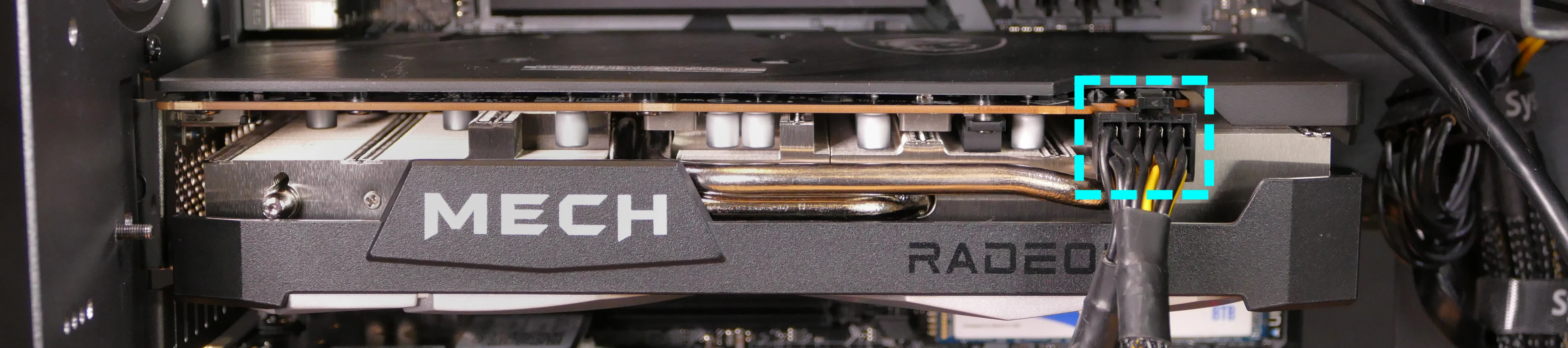
- If you’re removing a GPU, unplug the GPU power cable from the right side of the card. Hold down the latch on the connector while unplugging the cable.
- Unscrew the two back screws holding the PCIe bracket in place, and remove the PCIe bracket (or slide it into the rightmost position).
- Push back the latch on the motherboard to free the PCIe connection, then pull the card out of the slot.
- If the latch is difficult to reach between the GPU and the CPU heatsink, a long object (such as a screwdriver) can be used to push the latch.
- After inserting the new GPU into its slot, connect the power cable.
- Once the GPU is installed, replace the back PCIe bracket, side brace, and top case.
- The GPU brace finger may need to be adjusted before the side brace can be reinstalled.
Replacing the CMOS battery:
The CMOS battery supplies power to the system’s CMOS chip. UEFI settings and the computer’s hardware clock are stored on the CMOS. If your system doesn’t boot, you can reset the CMOS to force a low-level hardware reset. If your clock is constantly resetting, it’s likely your CMOS battery needs to be replaced.
Warning (ingestion hazard): Keep batteries out of reach of children. Death or serious injury can occur if ingested. If a battery is suspected to be swallowed or inserted inside any part of the body, seek immediate medical attention. In the US, you can also call the National Battery Ingestion Hotline for guidance: 1 (800) 498-8666
Tools required: Cross-head (Phillips) screwdriver
Time estimate: 20 minutes
Difficulty: Medium ●
Steps to replace the CMOS battery:
- Follow the steps above to remove the top case, remove the side brace, and remove the GPU.
- Pull the clip away from the CMOS battery.
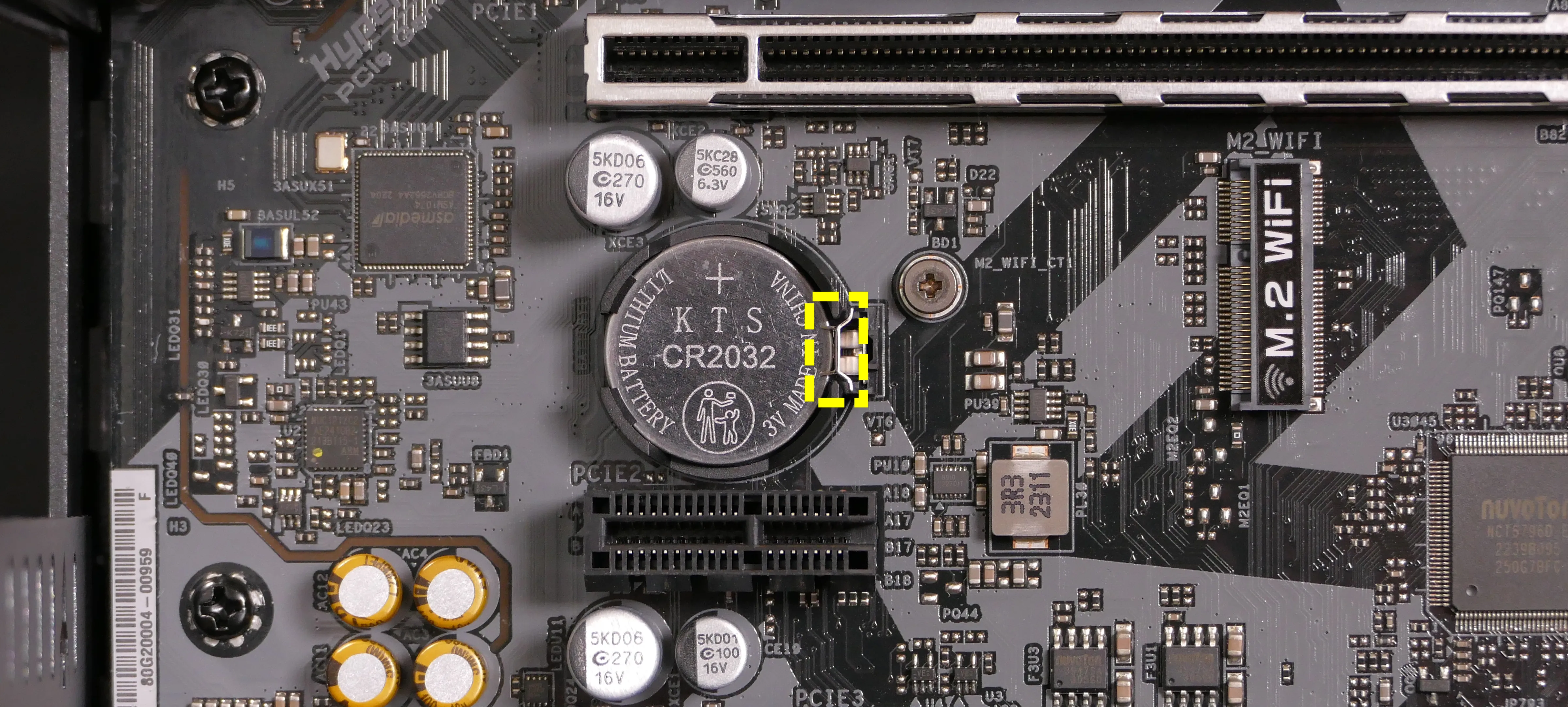
- Pull the CMOS battery out of its slot.
- If you are resetting the CMOS, hold down the power button for 10 seconds to discharge any residual energy in the system.
- Replace the CMOS battery starting with the left side of the slot (opposite from the clip).
- The positive side of the battery (with text) should face outward.
- Replace the GPU, side brace, and top case.
Replacing the wireless card:
Thelio Spark’s wireless card is a Ubit PCI Express x1 card with an Intel AX210 chipset. This chipset suppots WiFi 6E and Bluetooth 5.2. System76 installs custom external antennas that are shorter than the default Ubit antennas.
Tools required: Cross-head (Phillips) screwdriver
Time estimate: 20 minutes
Difficulty: Medium ●
Steps to replace the wireless card:
- Follow the steps above to remove the top case and remove the side brace.
- Unscrew the two back screws holding the PCIe bracket in place, and remove the PCIe bracket (or slide it into the rightmost position).
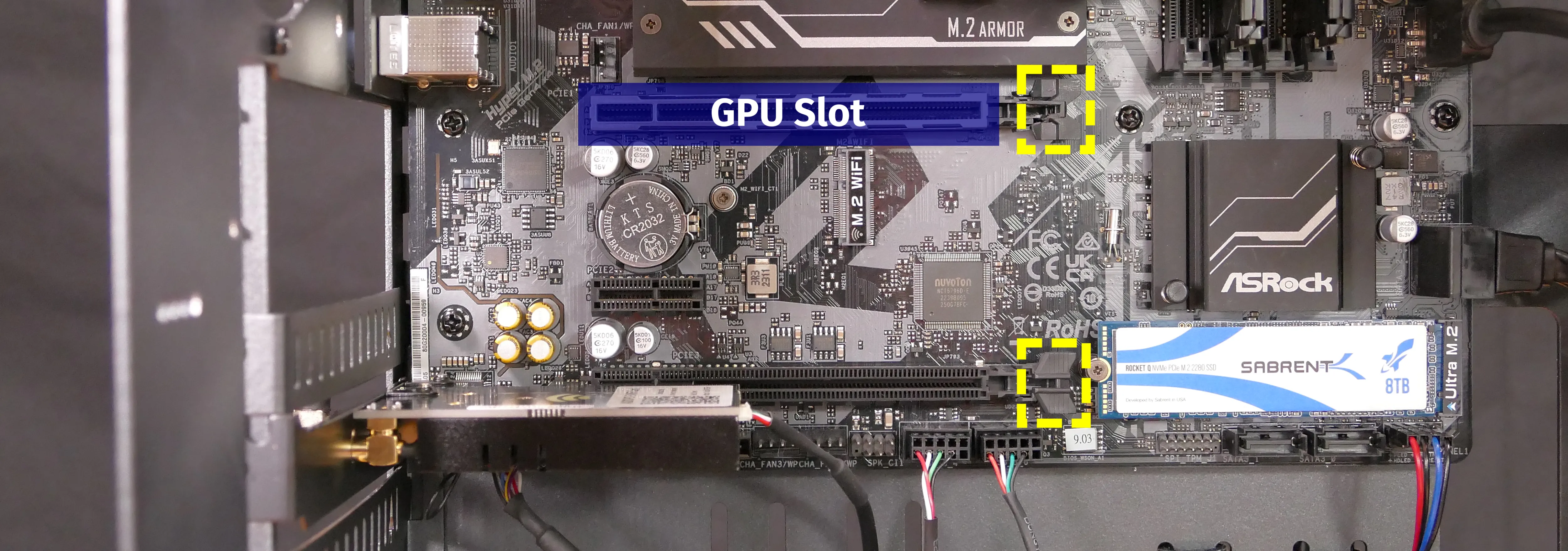
- Unplug the wireless card’s data cable from the
USB_5_6port on the motherboard, highlighted yellow below.- The cable may alternatively be plugged into the adjacent
USB_3_4port.
- The cable may alternatively be plugged into the adjacent
- Remove the wireless card from the PCIe slot.
- You may need to rotate the antennas to fit them through the PCIe slot cutout in the chassis.
- Install the new wireless card or reinstall the existing wireless card into the PCIe slot, screw in the antennas (if applicable), then ensure the data cable is plugged into both the white port on the wireless card (highlighted green above) and the
USB_5_6port on the motherboard.- The cable may alternatively be plugged into the adjacent
USB_3_4port if theUSB_5_6port is occupied by another component.
- The cable may alternatively be plugged into the adjacent
- Replace the back PCIe bracket, side brace, and top case.
Replacing the RAM:
Thelio Spark B1-N2 supports up to 128GB (4x32GB) of RAM. Factory configurations are limited to 64GB (4x16GB).
The RAM sticks are DDR4 DIMMs (non-ECC) running at a speed of up to 3200MHz. With aftermarket DIMMs, overclocked speeds of up to 5333 MHz may function but are not guaranteed.
If you’ve purchased new RAM, need to replace your RAM, or are reseating your RAM, follow these steps.
Tools required: Cross-head (Phillips) screwdriver
Time estimate: 15 minutes
Difficulty: Medium ●
Steps to replace the RAM:
- Follow the steps above to remove the top case and remove the CPU duct.
- If there’s no dedicated GPU installed, then removing the CPU duct is optional, but removal is still recommended to provide easier access to the RAM slots.
- To remove an existing RAM stick, flip the top latch away from the stick, then pull the stick out of the slot.
- The bottom of the RAM slot does not move.
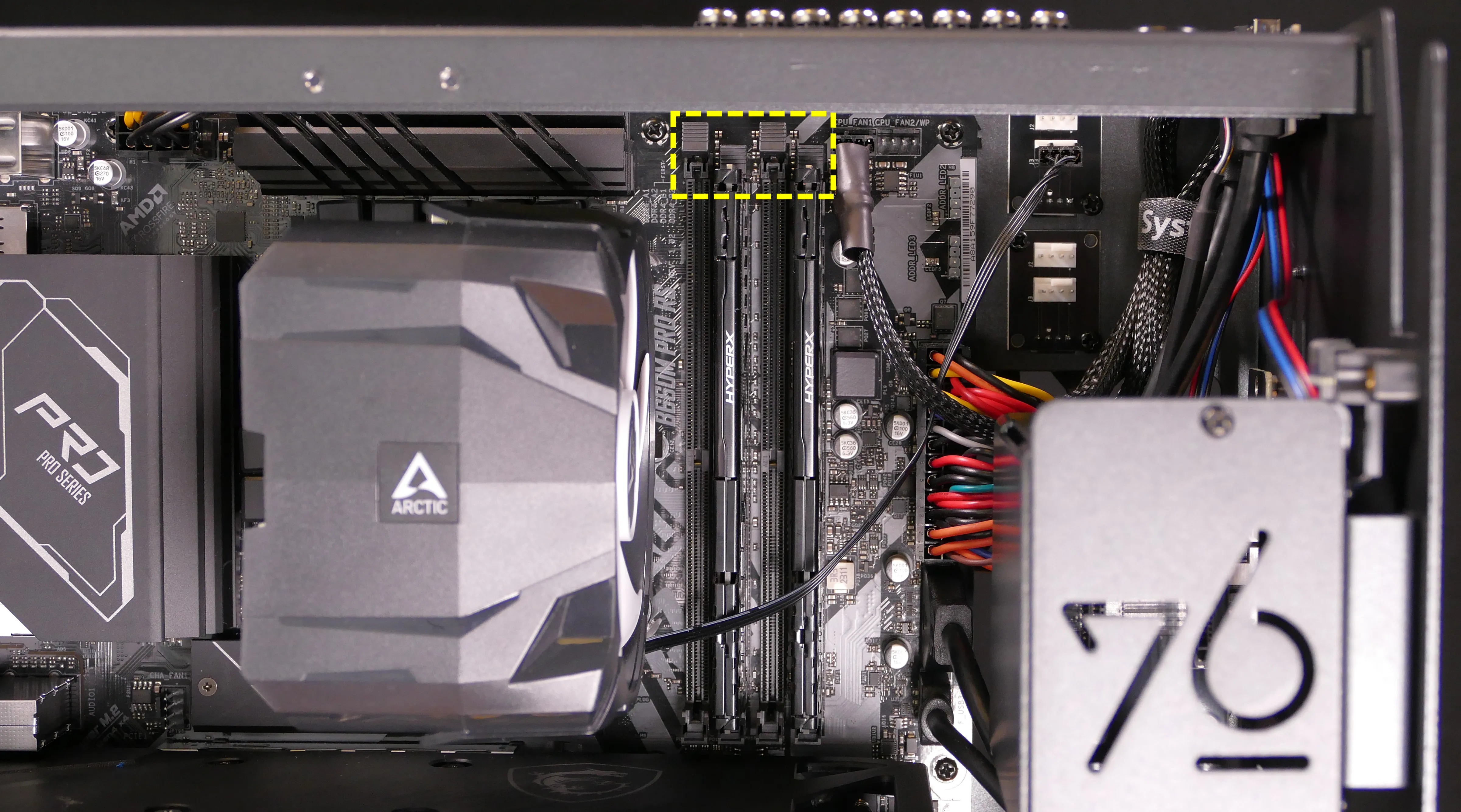
- Make sure the tabs on the top and bottom of the slot are open (pulled away from the slot), then insert the new RAM (or re-seat the existing RAM) into the slot.
- The RAM stick will only fit in one direction. The larger group of pins goes on top.
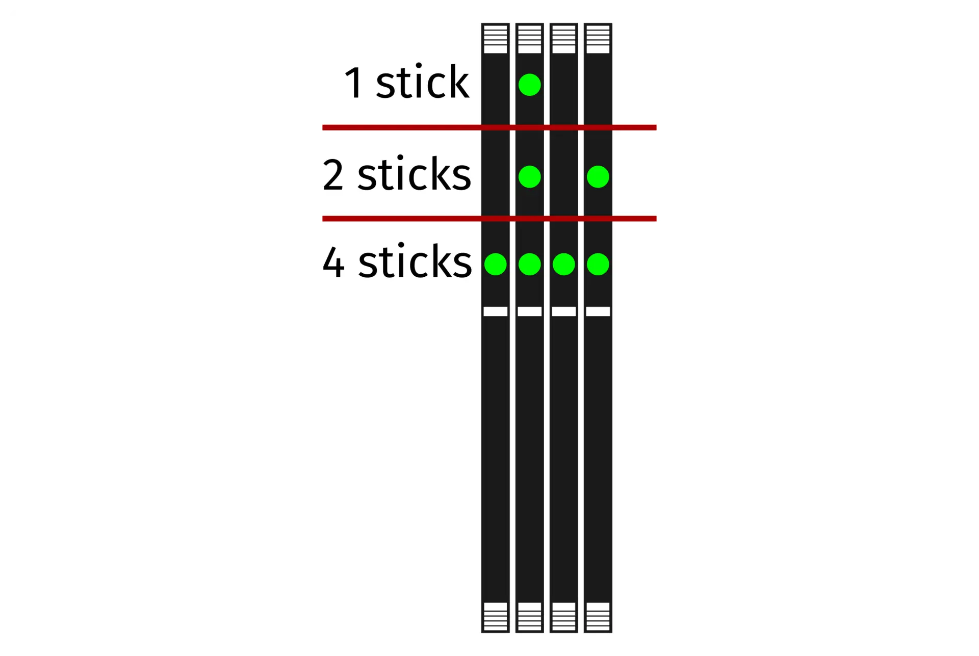
- Use the following guide for placement of the RAM sticks:
- Replace the top case.
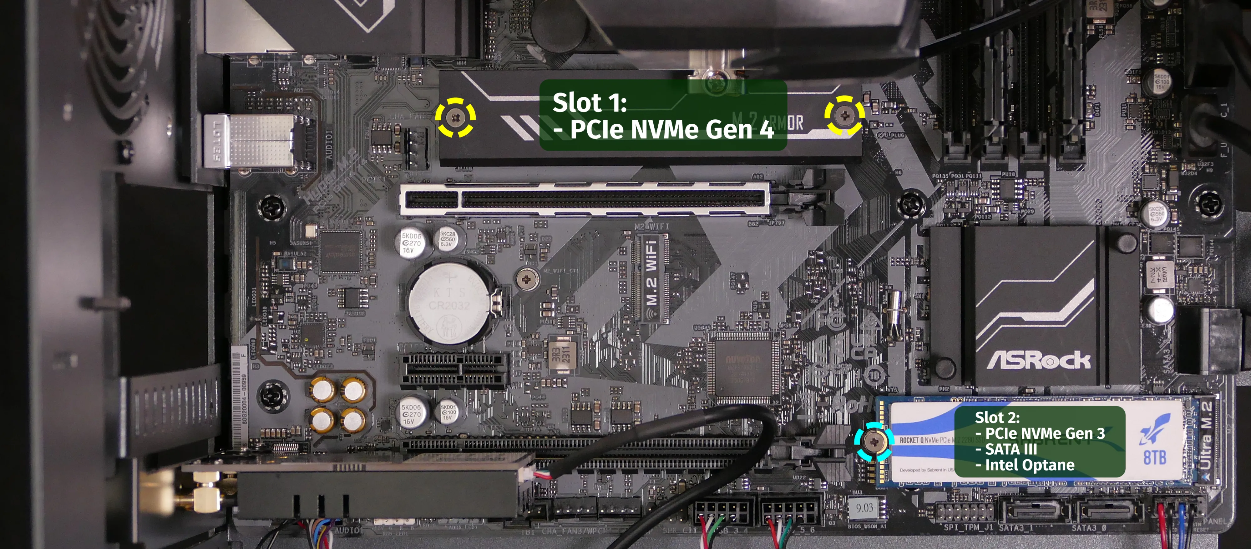
Replacing the M.2 drives:
Thelio Spark B1-N2 has two M.2 storage slots. All four slots are M-key and size 2280.
- Slot 1 supports PCIe NVMe Gen 4.
- Slot 2 supports PCIe NVMe Gen 3, SATA III, and Intel Optane.
Tools required: Cross-head (Phillips) screwdriver
Time estimate: 30 minutes
Difficulty: Medium ●
Steps to replace the M.2 drive:
- Follow the steps above to remove the top case.
- For Slot 1, remove the CPU duct.
- Removing the GPU is not required, but makes accessing Slot 1’s screws easier.
- For Slot 2, remove the side brace.
- For Slot 1, remove the CPU duct.
- For Slot 1, unscrew and remove the M.2 heatsink. For Slot 2, unscrew the screw opposite from the slot.
- For Slot 1, pull the M.2 heatsink directly away from the motherboard to break the seal of the thermal tape, then slide the M.2 heatsink down and out from behind the CPU heatsink.
- For both slots, the existing M.2 drive (if installed) will pop up at a 30-degree angle from the motherboard.
- Remove the existing M.2 drive by pulling it out of the slot.
- Insert the new M.2 drive into the slot and hold it in place.
- Replace the M.2 heatsink and/or M.2 screw(s).
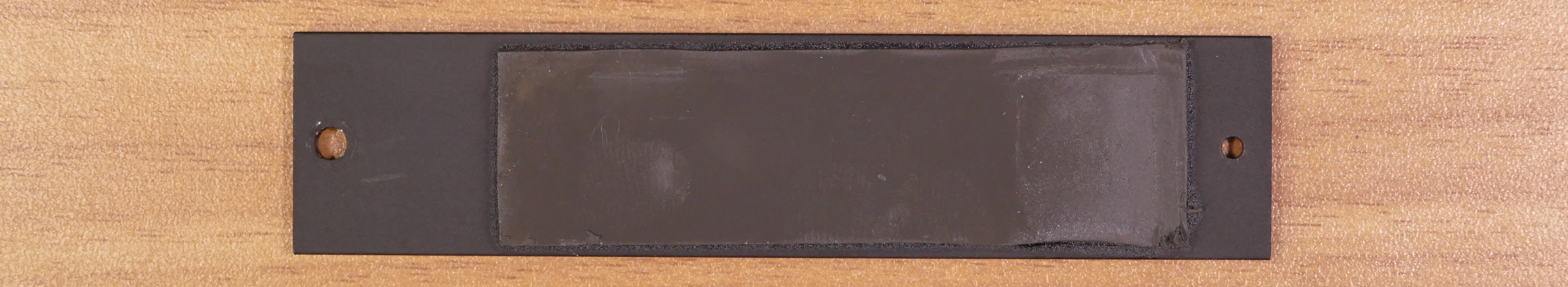
- Because Slot 1 is always populated in factory configurations, the M.2 thermal tape should already be applied and exposed on the M.2 heatsink. The thermal tape is shown below.
- Replace the CPU duct, GPU, side brace, and top case as applicable.
Replacing the CPU fans:
Thelio Spark B1-N2 contains two CPU fans. One is mounted on the CPU duct, and one is mounted on the CPU heatsink.
The heatsink-mounted CPU fan is built onto the cooler’s plastic molding. While it can be removed, replacements generally can’t be obtained separately from the heatsink.
Tools required: Cross-head (Phillips) screwdriver
Time estimate: 25 minutes
Difficulty: Medium ●
Steps to replace the duct-mounted CPU fan:
- Follow the steps above to remove the top case and remove the CPU duct.
- Free the fan cable from the velcro loop, highlighted cyan below.
- Unscrew the four screws (two on each side) holding the fan bracket onto the duct.
- Removing the bracket from the duct is not required to remove the fan, but it makes installing the fan much easier.
- Unscrew the four screws attaching the bracket to the fan.
- When reinstalling the fan into the CPU duct:
- The spinning side should face inward (towards the front of the chassis).
- The cable should point towards the closed corner of the top side of the duct (the top-right corner, when viewed from the back); the side of the fan where the cable originates should match the side of the duct with the velcro strap.
- Overtightening the fan bracket’s screws may cause fan noise; if the fan is creating excessive noise, try slightly loosening some of the screws.
Steps to replace the heatsink-mounted CPU fan:
- Follow the steps above to remove the top case and remove the CPU duct.
- For easier access to the fan tabs, it’s also recommended to remove the side brace and remove the dedicated GPU (if installed).
- If the heatsink-mounted fan is still plugged in, unplug it from the top splitter board in the front corner of the machine.
- Pull the top and bottom edges of the fan’s plastic molding away from the heatsink it’s clipped onto; the fan can be pulled away from the heatsink once the plastic molding’s tabs are held far enough away from the heatsink.
- Repeat the process for the bottom clip, then pull the fan and clips away from the CPU heatsink.
- When reinstalling the CPU heatsink fan, the side with a stationary cover should face the heatsink, while the spinning side should face the front of the chassis.
- The cable should point towards the bottom inner corner (bottom-left when viewed from the back of the case.)
Replacing the CPU cooler and CPU:
The CPU cooler dissipates heat from the CPU to the heatsink, where the CPU fans expel it from the system. Depending on your climate and the age of the machine, replacing the thermal paste between the CPU and the cooler/heatsink may help the system run cooler.
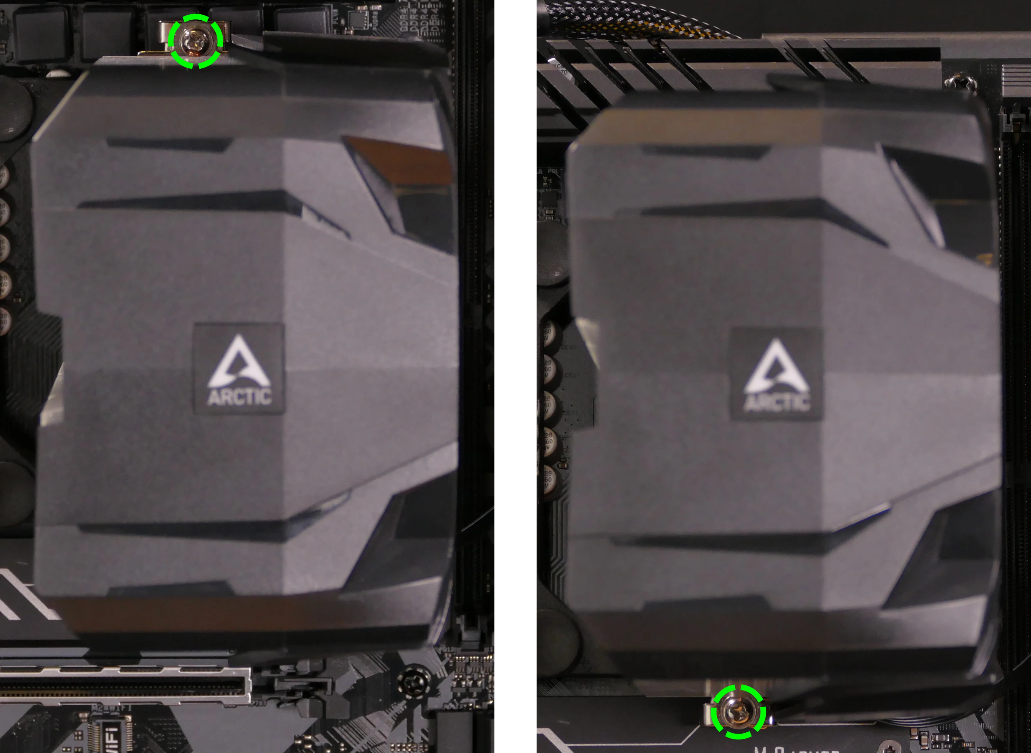
The CPU uses an Intel LGA 1700 socket. The CPU cooler is an Arctic Freezer 7 X Rev 3.
Tools required: Cross-head (Phillips) screwdriver, thermal paste
Time estimate: 45 minutes
Difficulty: High ●
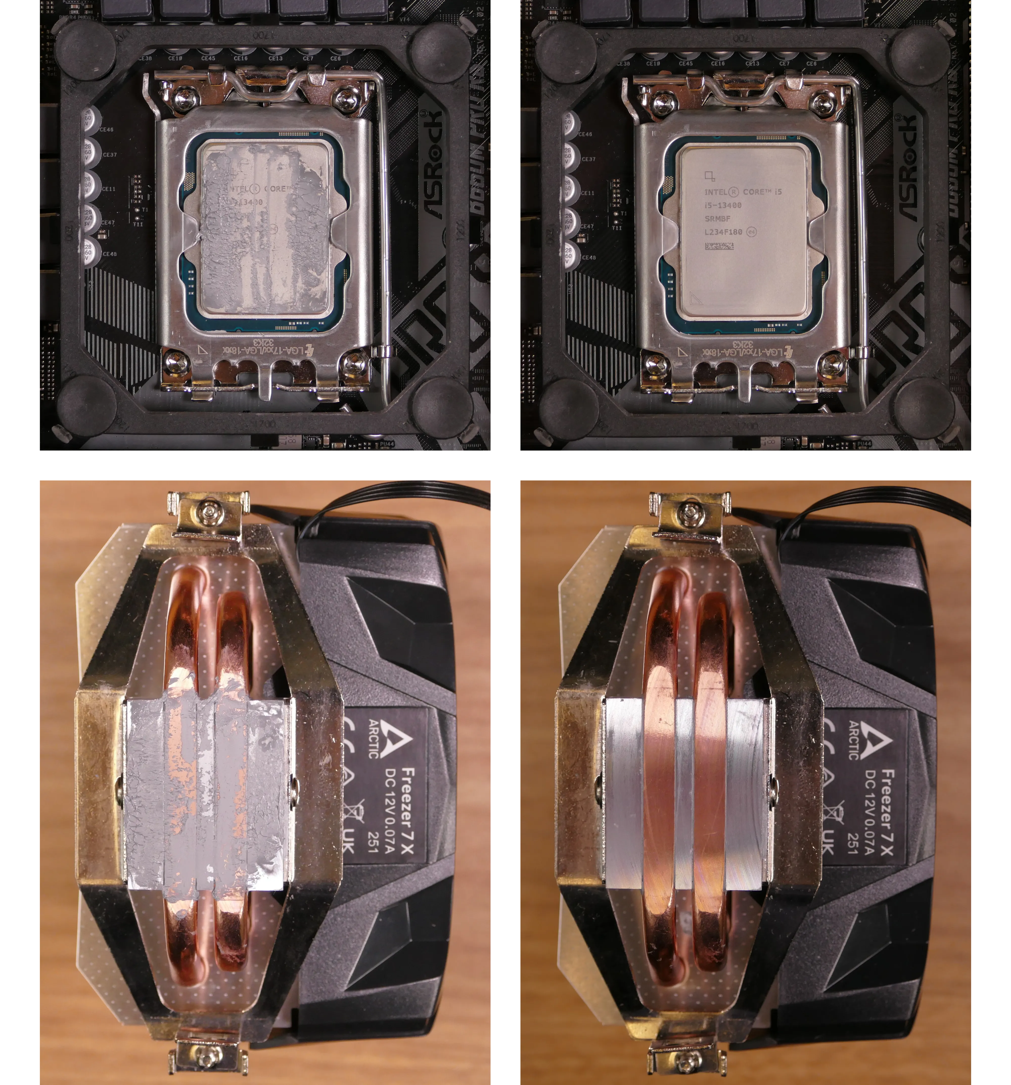
Steps to remove the CPU cooler/thermal paste:
- Follow the steps above to remove the top case, remove the side brace, remove the CPU duct, and remove the GPU.
- Unplug the heatsink-mounted CPU fan unless it’s already been removed.
- While holding the CPU cooler in place so it doesn’t fall, loosen the screws on the top and bottom of the CPU cooler holding it onto the mounting bracket.
- If you unscrew the screws too far, the 90-degree clips will detatch from the vertical mounting bar. Reattach them facing inwards when reinstalling the cooler.
- Pull the cooler away from the CPU, alternating between the top and bottom to free the 90-degree clips from the mounting bracket.
- Using a paper towel, clean the existing thermal paste off of the heatsink and CPU. You may also use a small amount of rubbing alcohol if the old paste is dried or difficult to remove.
Steps to replace the CPU:
- Place the computer on its side so the motherboard is facing up.
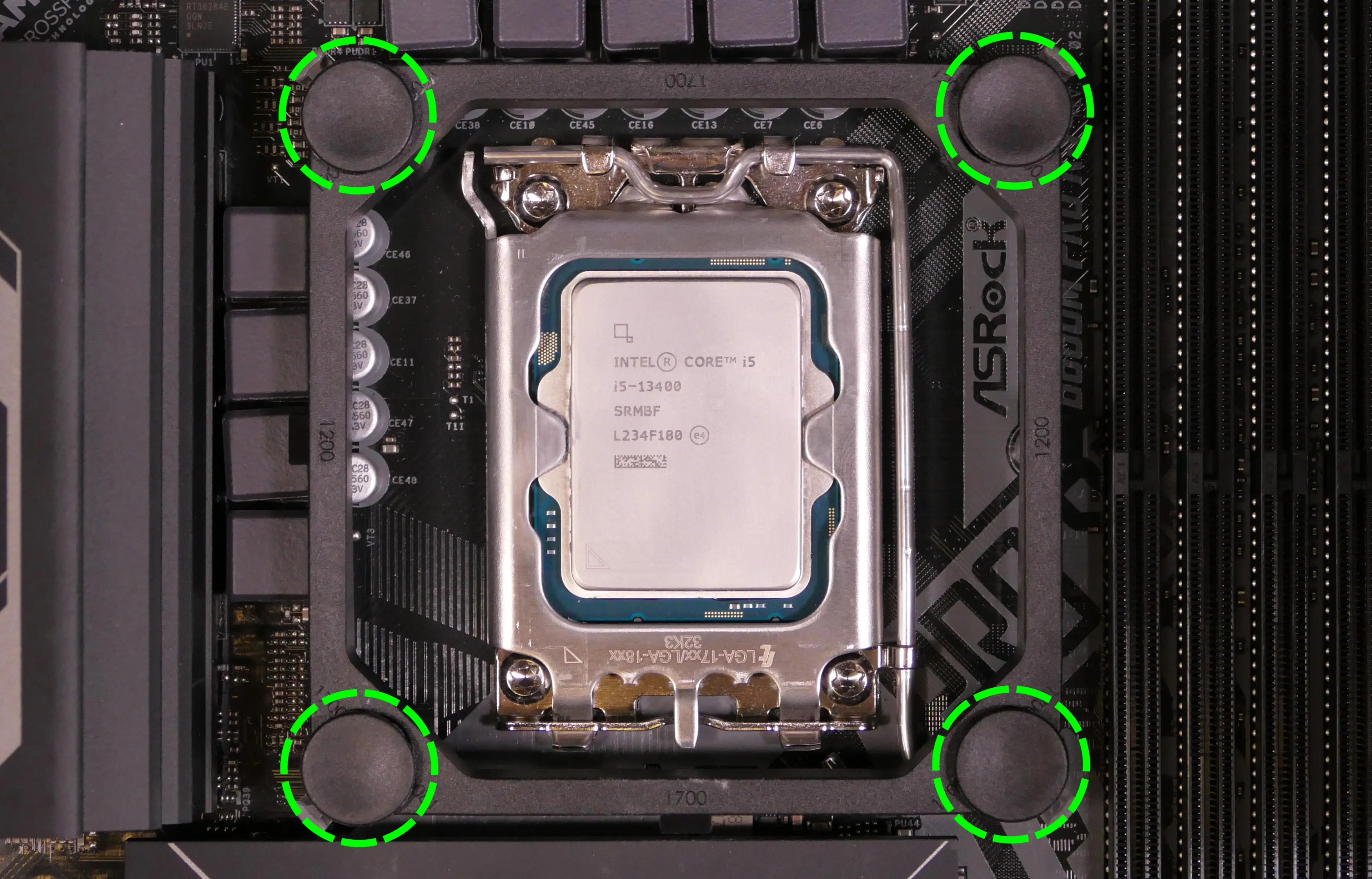
- Remove the RAM to provide easier access to the cooler mounting bracket’s plastic retention pins.
- Pull the plastic retention pins out of the four corners of the cooler mounting bracket, then remove the cooler mounting bracket.
- Push the locking lever outward until it’s able to spring away from the motherboard.
- Caution: the locking lever may spring up with significant force when freed.
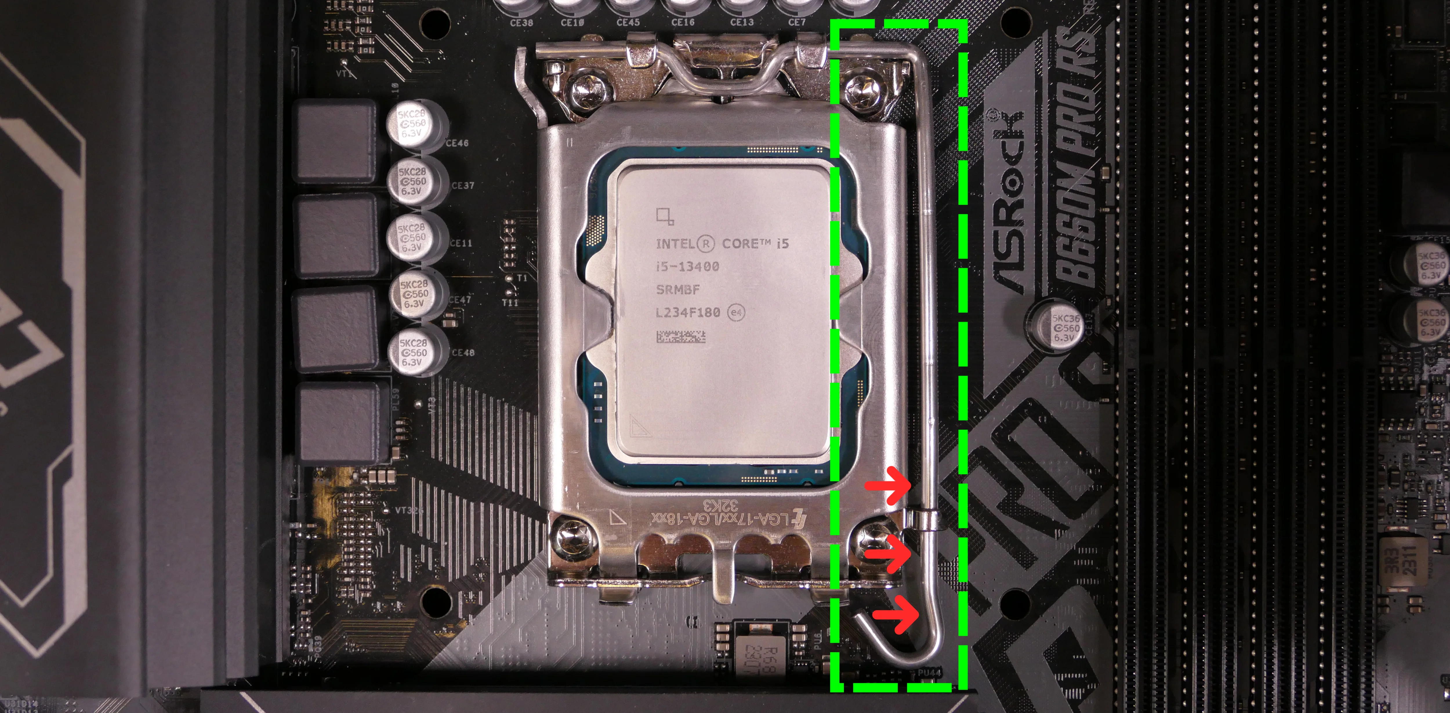
- Flip the CPU holder away from the CPU.
- The CPU holder opens in the opposite direction from the locking lever.
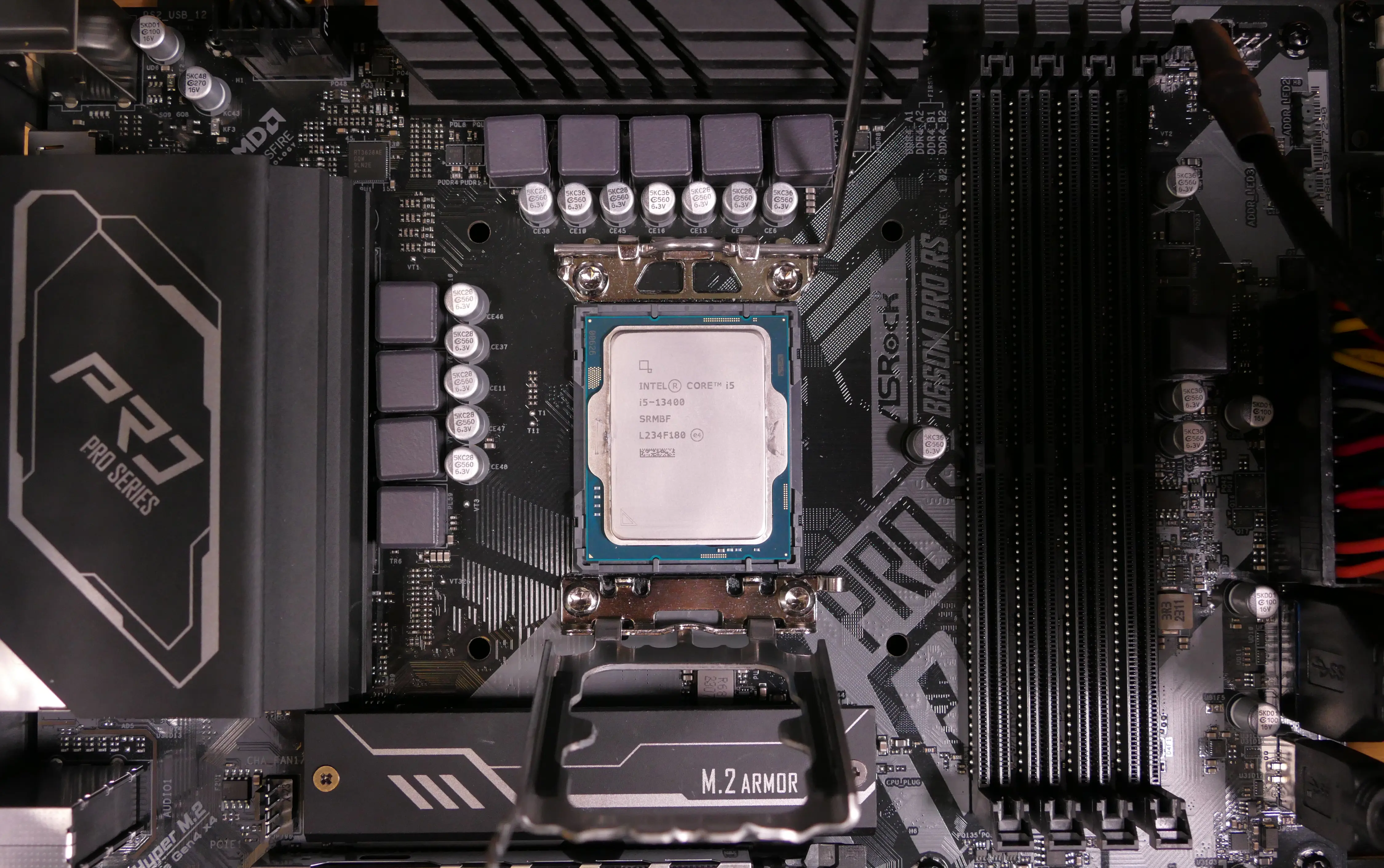
- Carefully lift the CPU out of the CPU socket.
- Be careful not to bend any of the gold pins on the CPU socket, and do not touch the gold pads on the CPU.
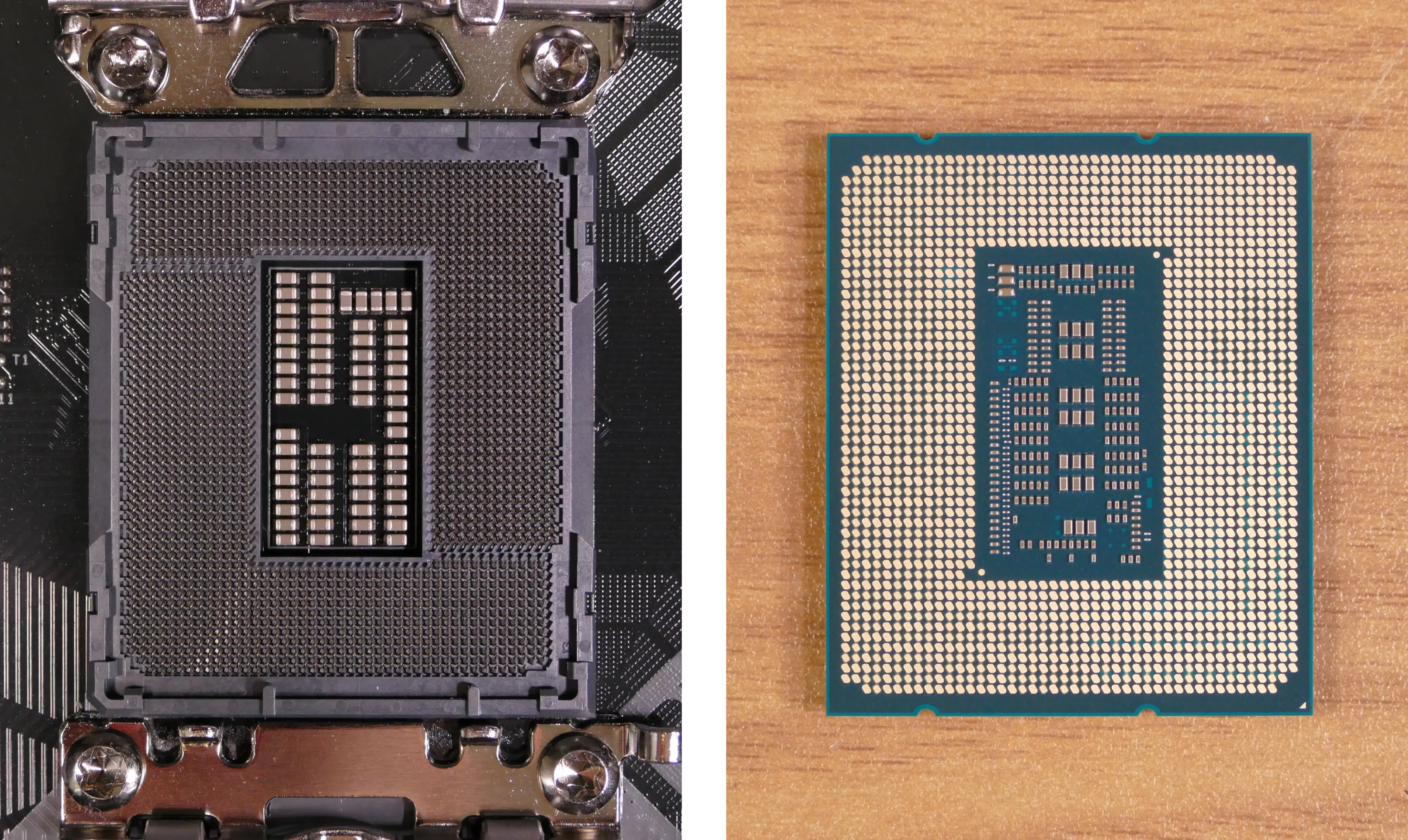
- Gently place the new CPU into the socket.
- The triangle on the CPU should be oriented to match the triangle on the CPU cover, pointing towards the bottom left of the motherboard.
- Flip the CPU cover back onto the CPU and push the locking lever down into place.
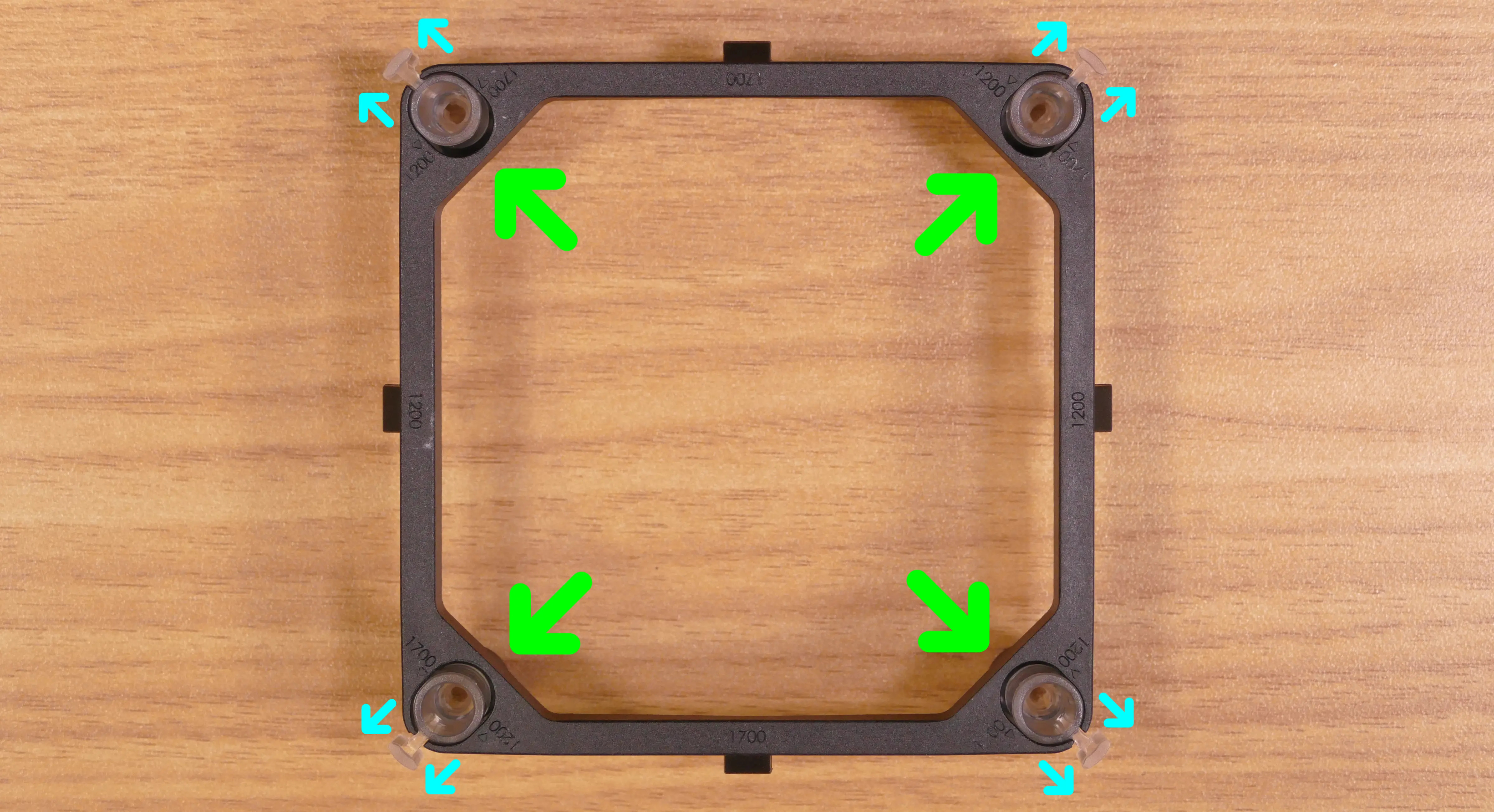
- Reinstall the cooler mounting bracket by lining it up with the holes in the motherboard and pushing the plastic retention pins back into place.
- Ensure that the transparent sleeves in the corners of the mounting bracket are pulled outwards to the
1700position. - The orientation of the cooler mounting bracket doesn’t matter. By default, the
1700number is on the top and bottom of the bracket, while the1200number is on the left and right.
- Ensure that the transparent sleeves in the corners of the mounting bracket are pulled outwards to the
Steps to install the thermal paste/CPU cooler:
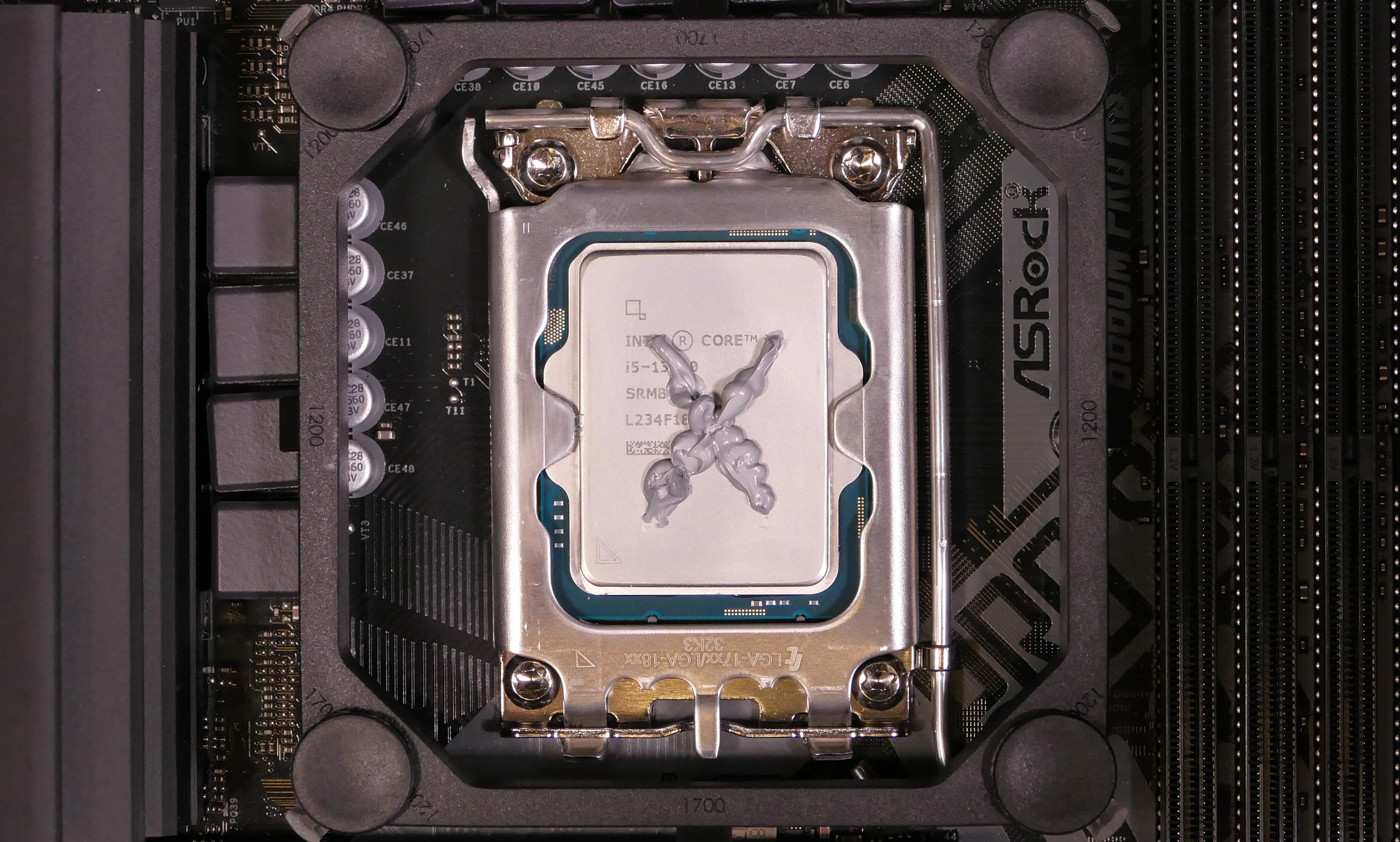
- Draw an
Xshape of thermal paste onto the CPU.
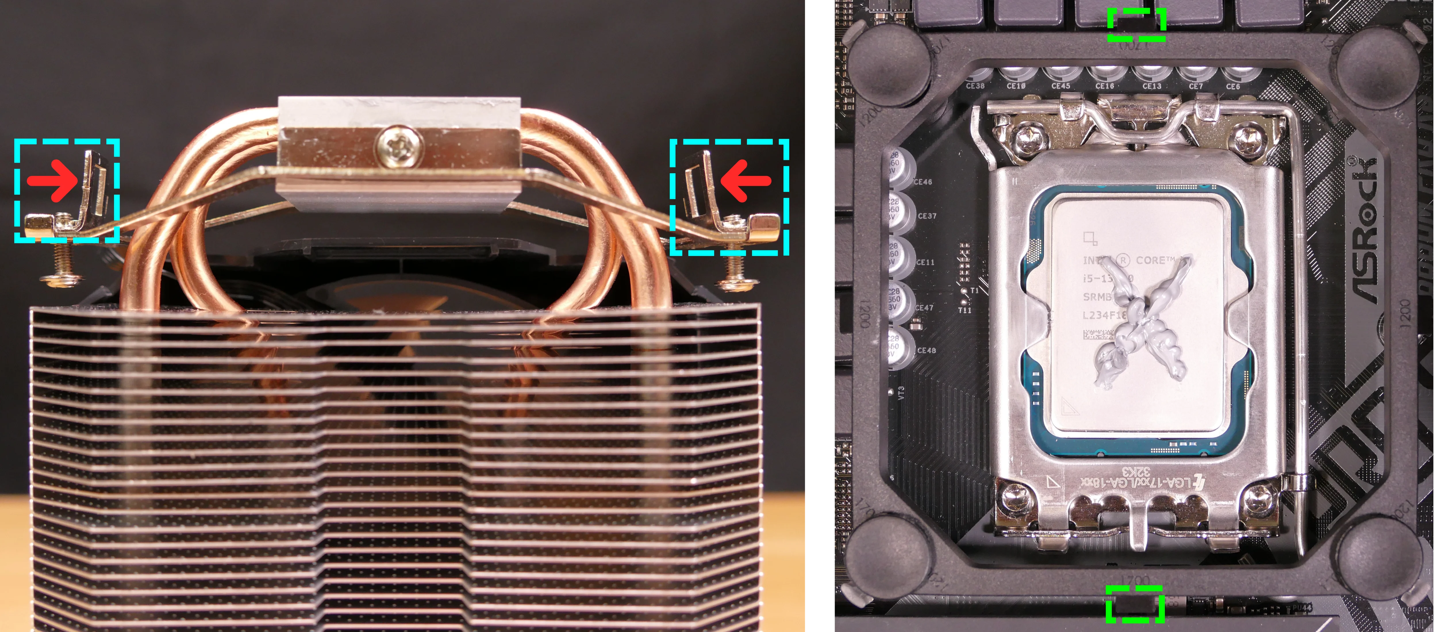
- Place the CPU cooler onto the CPU; while holding it in place, tighten the screws on the top and bottom of the vertical mounting bar to tighten the 90-degree clips onto the mounting bracket.
- The cooler should be oriented so the fan is on the right side (towards the front of the case).
- The 90-degree clips must be oriented inward to fasten onto the mounting bracket.
- Set the computer upright, then reinstall the cooler-mounted CPU fan (if necessary), RAM, CPU duct, GPU, side bracket, and top case.
Replacing the power supply:
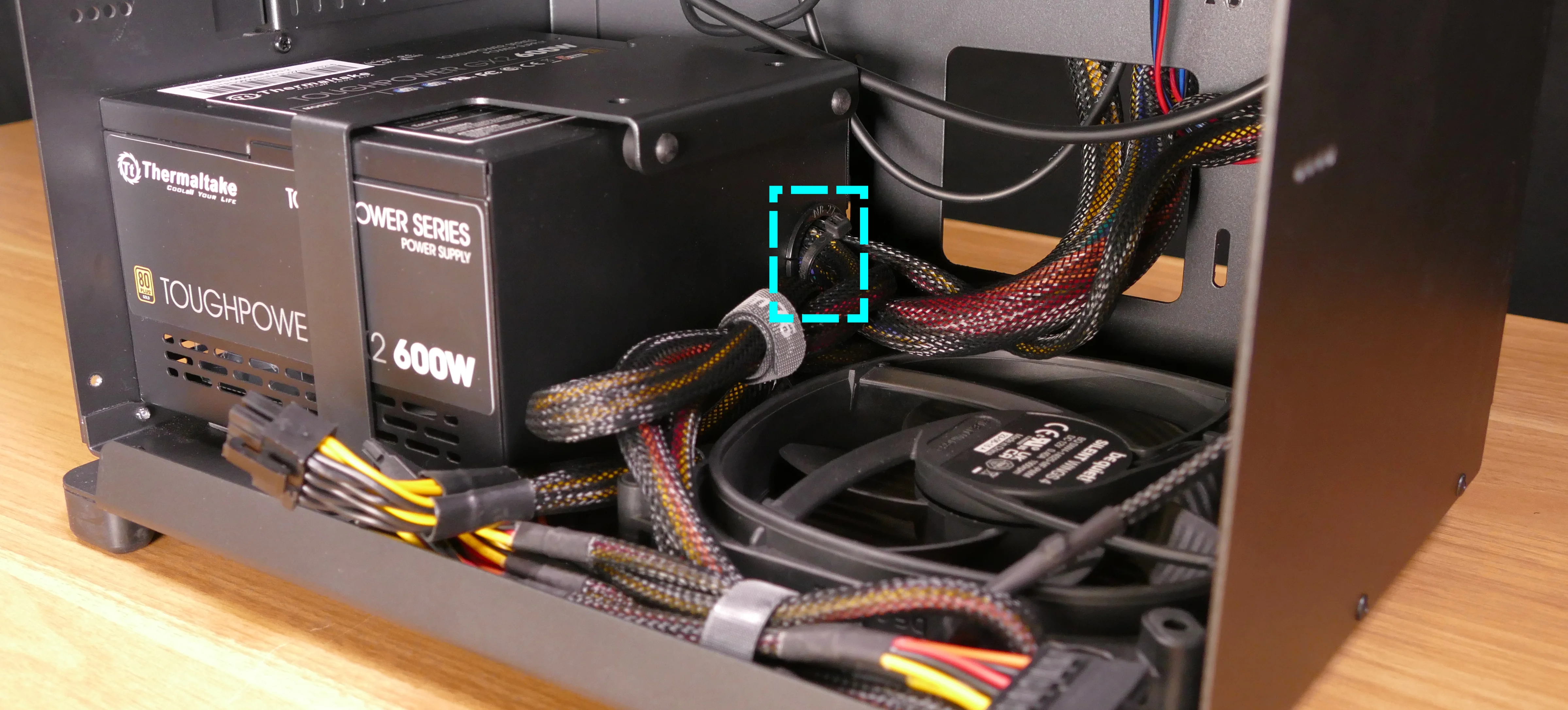
The power supply unit (PSU) can be replaced with another unit of the same model. One possible preinstalled model is the Thermaltake Toughpower GX2 600W (80+ Gold).
The PSU is not modular, so all of its cabling will need to be unplugged and removed, then the new PSU’s cabling will need to be run through the system and connected.
Tools required: Cross-head (Phillips) screwdriver
Time estimate: 45 minutes
Difficulty: Medium ●
Steps to replace the power supply:
- Follow the steps above to remove the top case, remove the side brace, and unplug the GPU.
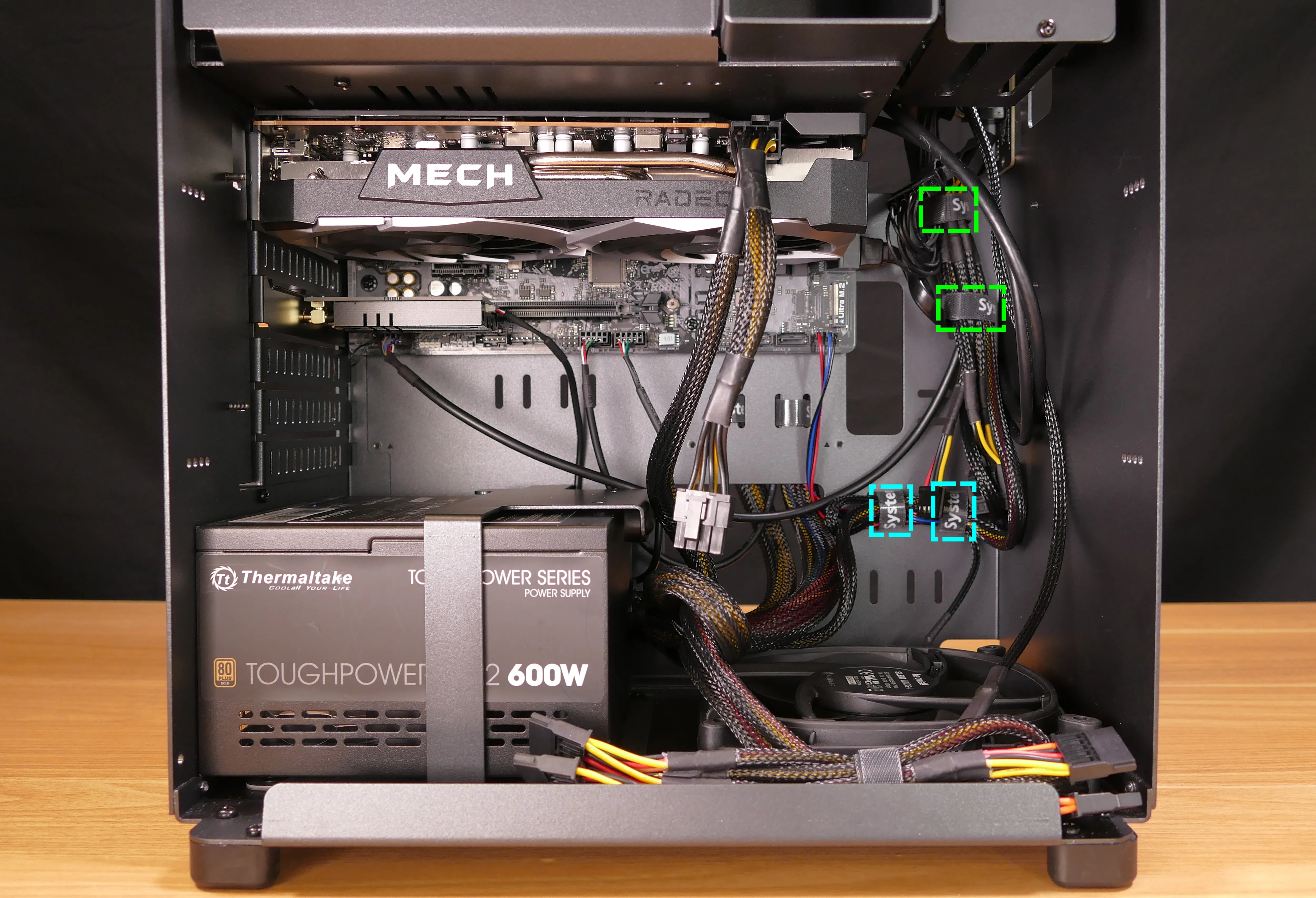
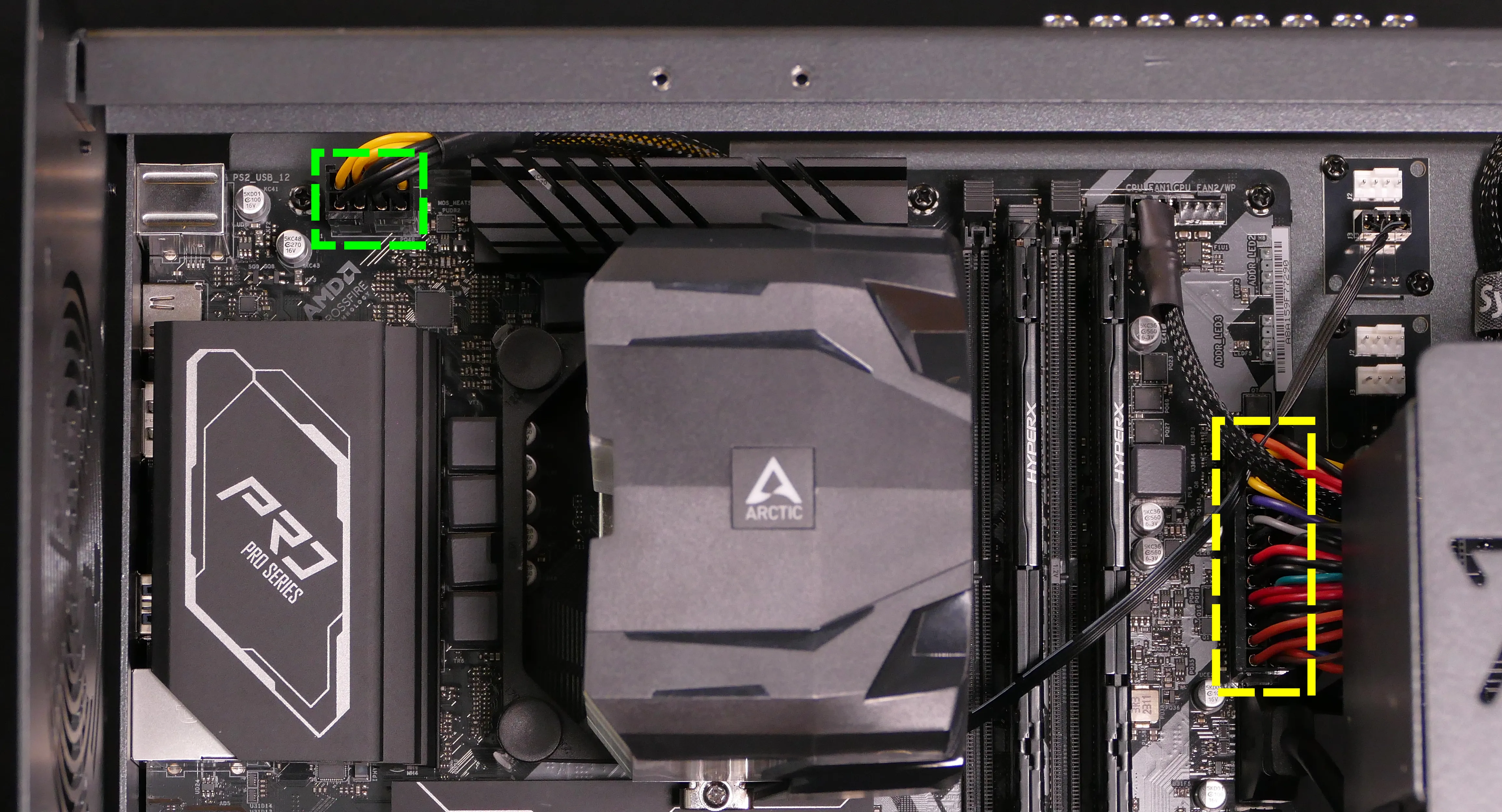
- Locate and unplug all of the cables emanating from the power supply (shown below), including the following:
- The 8-pin CPU power cable labeled
ATX12V1near the top-left of the motherboard, highlighted green below. - The 24-pin motherboard power cable labeled
ATXPWR1on the right side of the motherboard, highlighted yellow below.
- The 4-pin Berg connector labeled
POWER1on the Thelio Io board.
- The 4-pin Berg connector labeled
POWER0on the SATA backplane.
- Unscrew and remove the PSU bracket.
- One screw is located on the opposite side of the case.
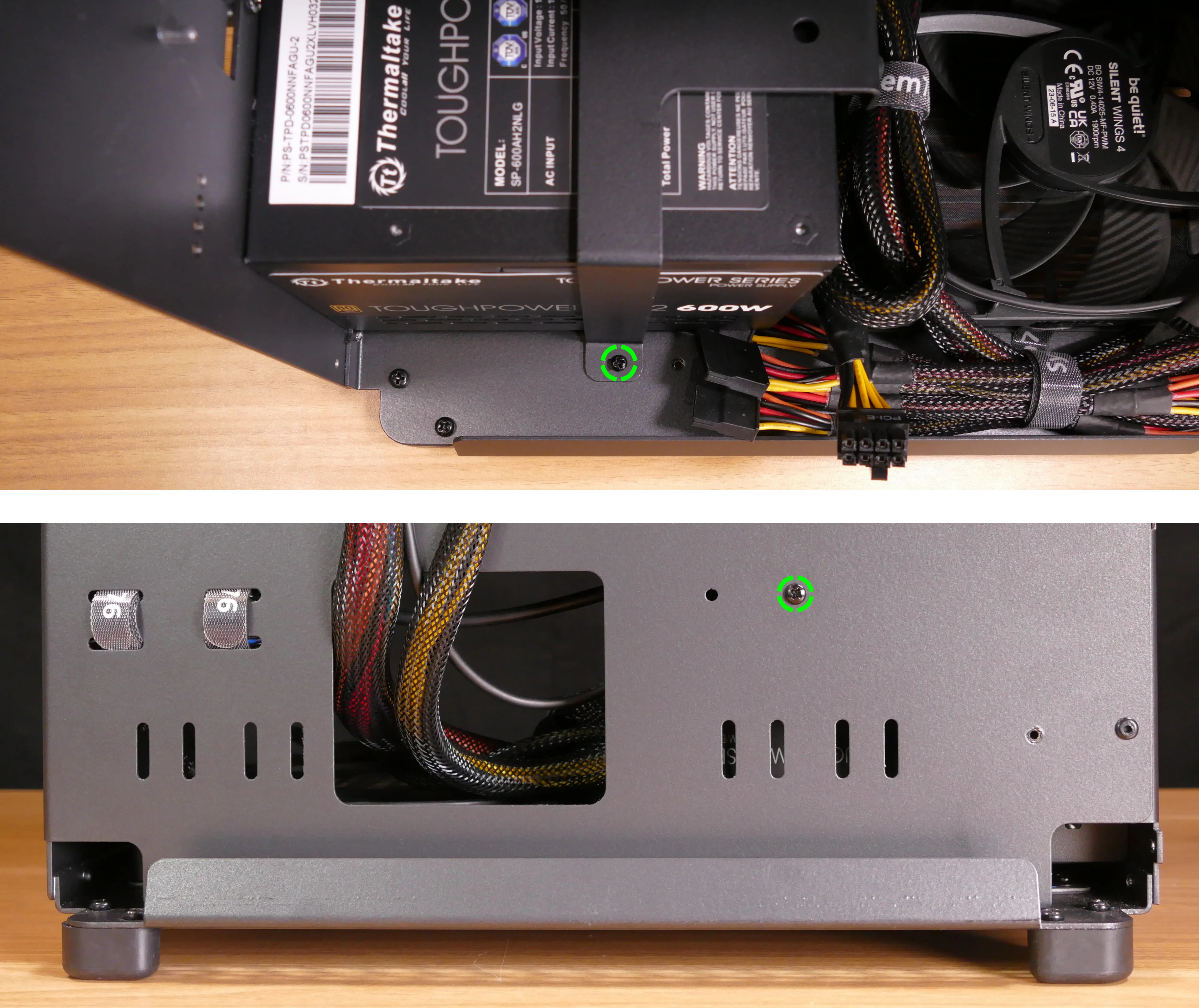
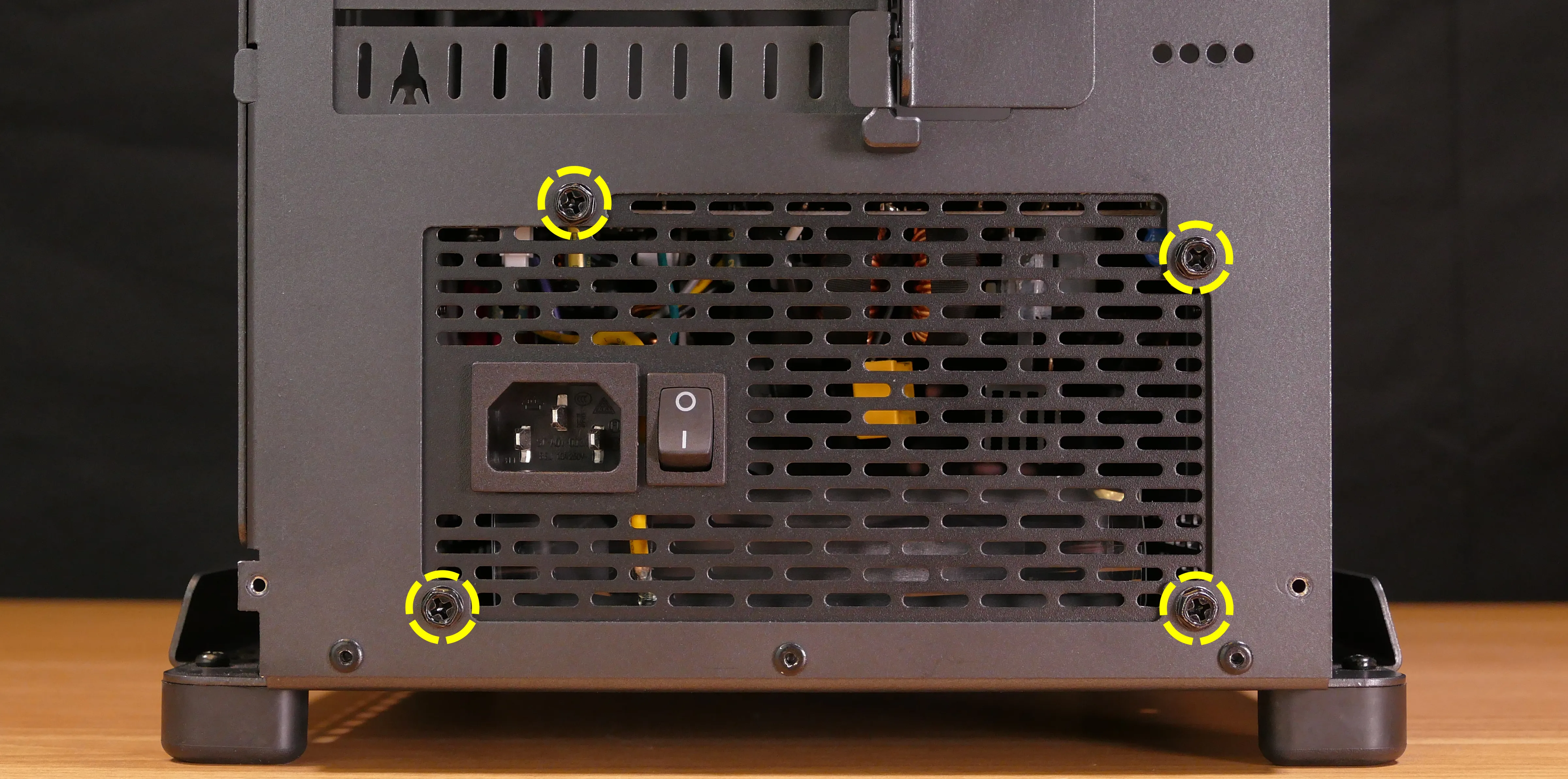
- Unscrew the four screws holding the PSU in from the back of the case.
- Remove/replace the PSU.
- The replacement PSU should be installed with the fan facing the bottom of the case.
- Hold the PSU up to the screwholes in the back of the case while attaching it.
- Run the new PSU’s wires through the system (securing them with velcro straps where necessary), then plug in the new PSU’s wires into the motherboard (including the CPU plug), Thelio Io board, SATA backplane, and dedicated GPU (if installed).
Replacing the Thelio Io board:
Named after Jupiter’s moon Io, the Thelio Io daughterboard handles the front power button and fan control. Thelio Spark B1-N2 uses Thelio Io version 2. If the Thelio Io board becomes defective, it can be replaced using the instructions below.
Tools required: Cross-head (Phillips) screwdriver
Time estimate: 30 minutes
Difficulty: High ●
Steps to replace the Thelio Io board:
- Follow the steps above to remove the top case.
- The CPU duct and side brace can optionally be removed to provide easier access to the cabling.
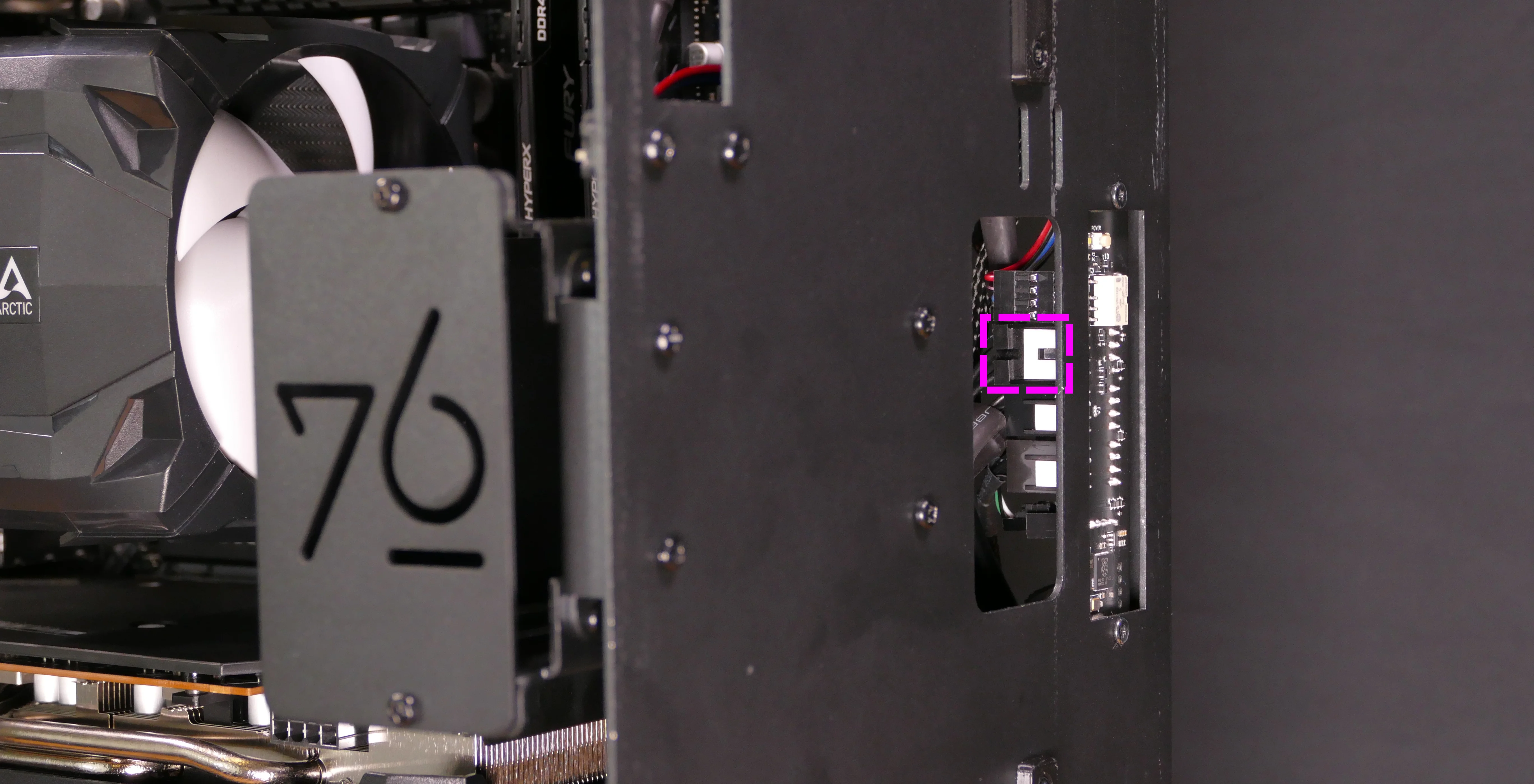
- Use the cutouts on the front right corner of the chassis to unplug all cabling from the Thelio Io board.
- The topmost connector requires pulling the white tab while unplugging.
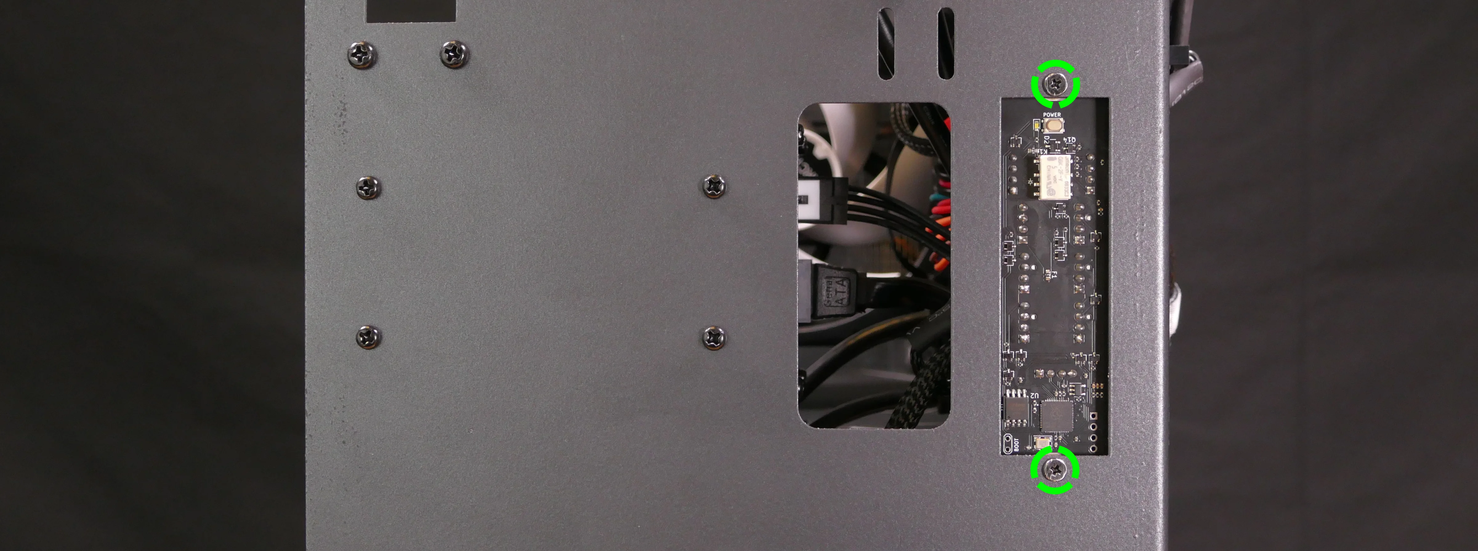
- Unscrew the two screws holding the daughterboard on from the front of the chassis.
- Screw in the new Thelio Io board and reconnect the wiring.
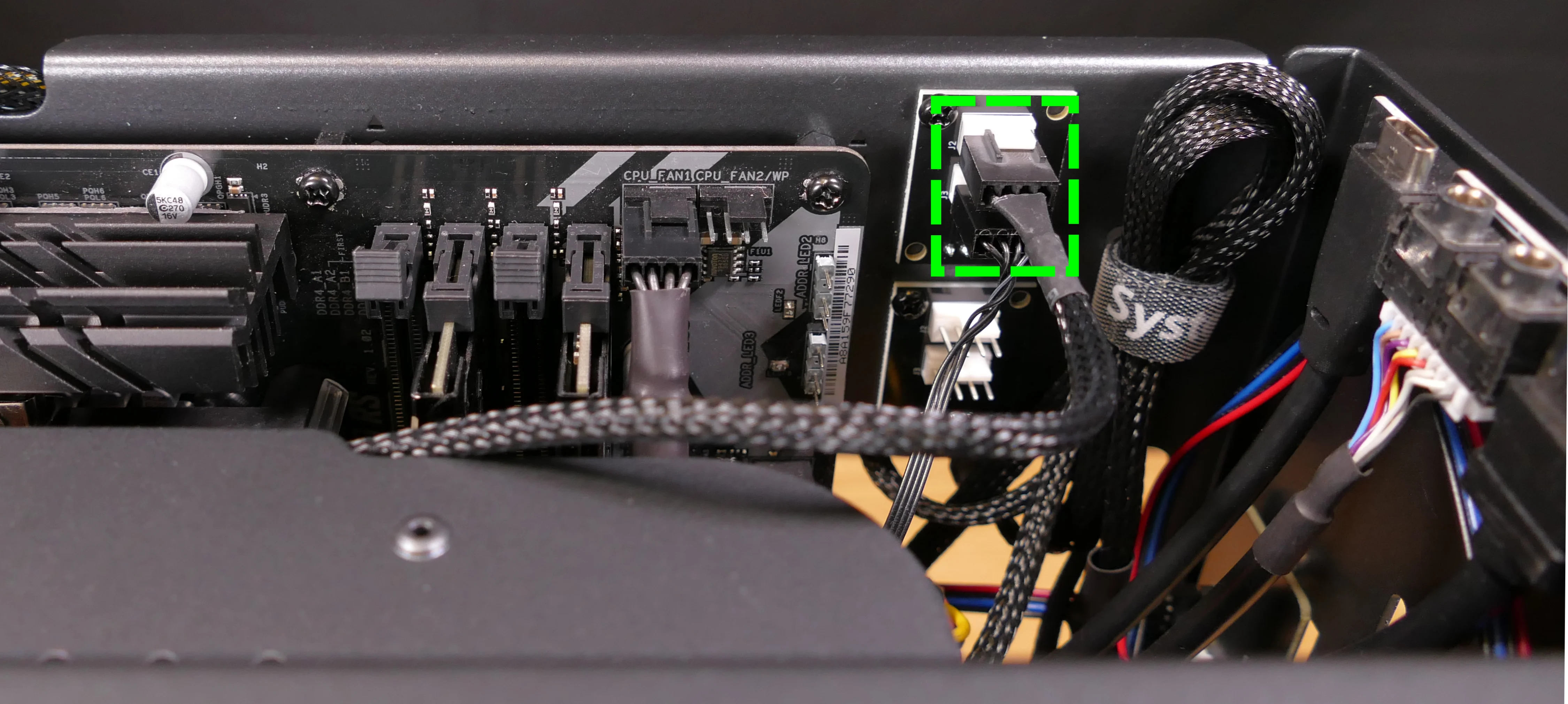
Thelio Io wiring guide:
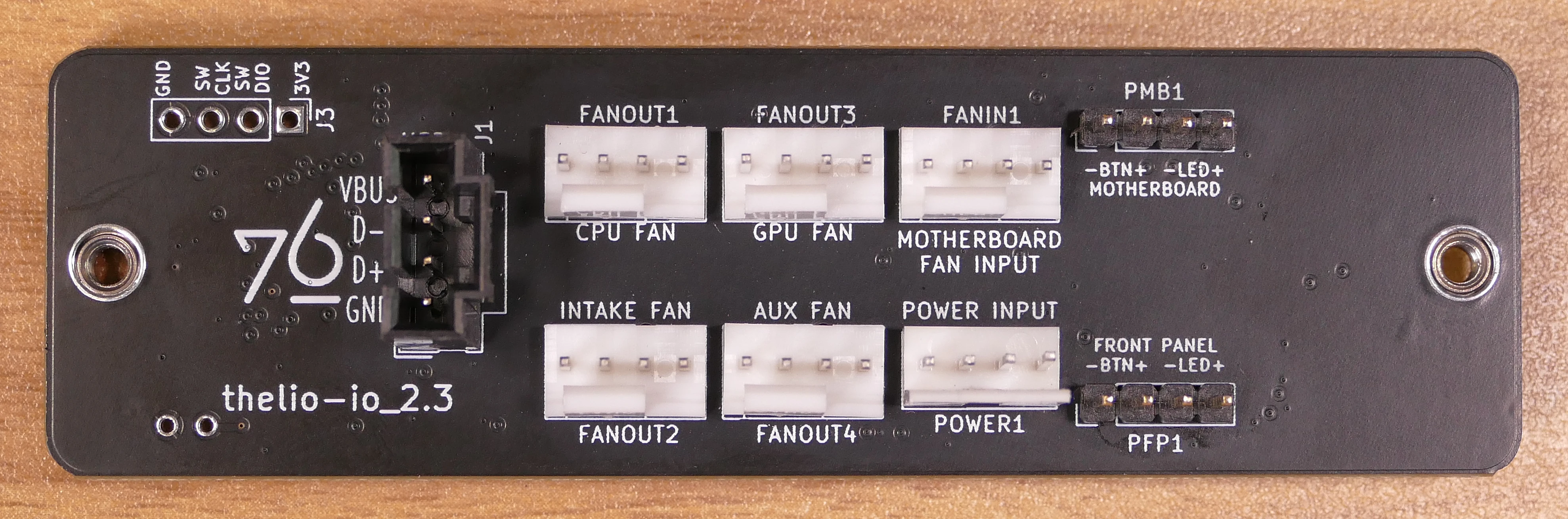
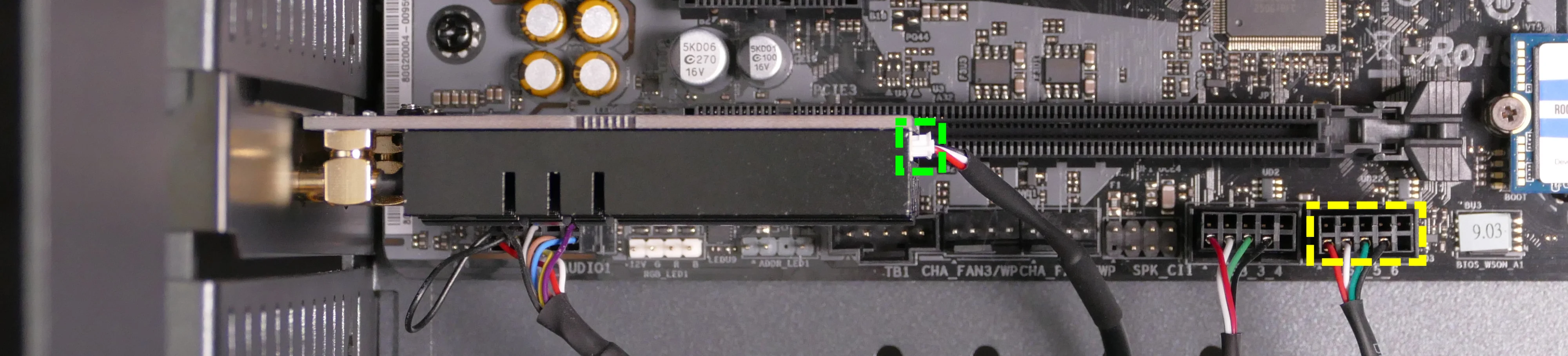
-
When wiring the Thelio Io board, refer to the port labels and the following guide.
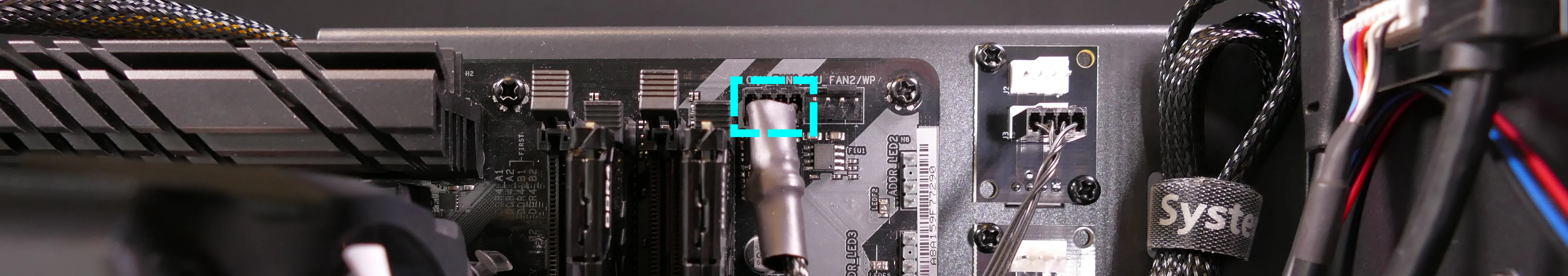
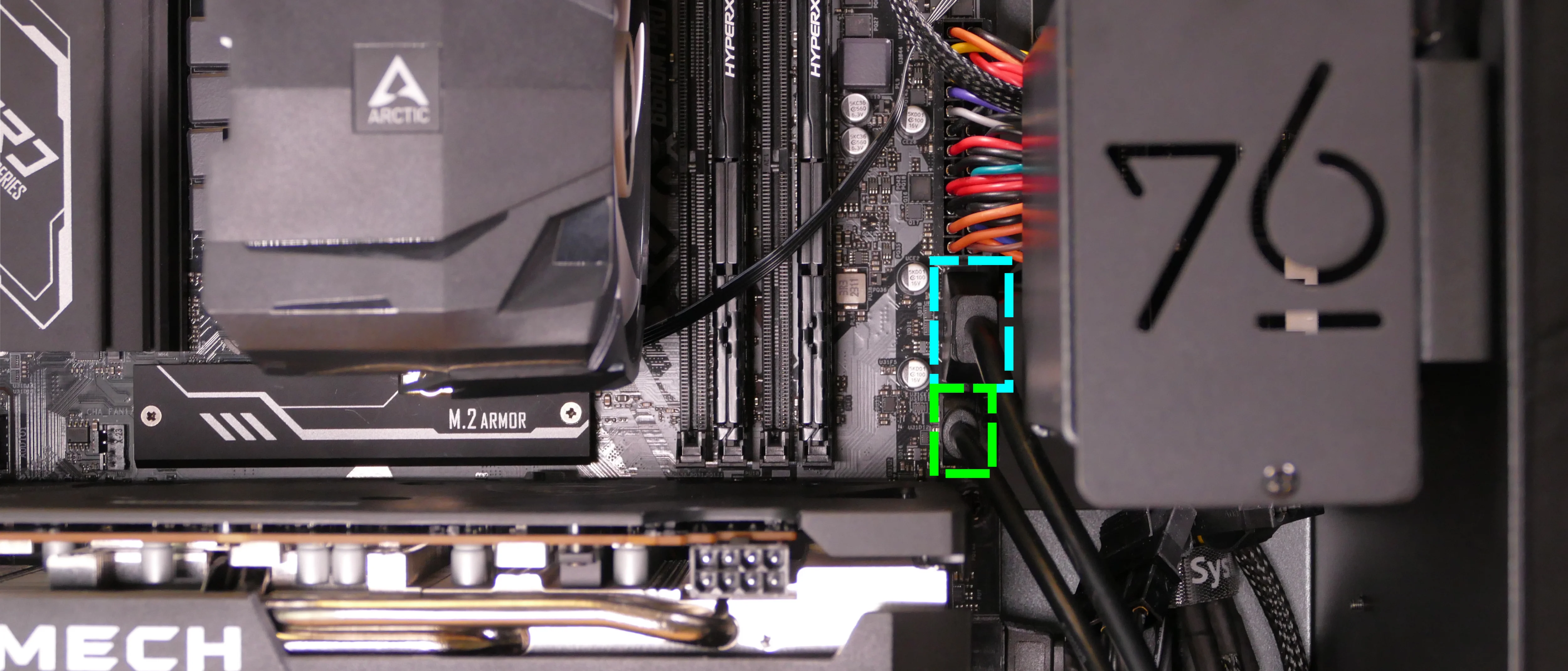
FANOUT1/CPU FAN- to the top fan splitter (connecting to the CPU fans).FANOUT4/AUX FAN- to the bottom fan splitter (below the CPU fan splitter).FANOUT2/INTAKE FAN- to the bottom case fan.FANOUT3/GPU FAN- to the side brace fan splitter (disconnected by default).FANIN1/MOTHERBOARD FAN INPUT- to theCPU_FAN1header at the top right of the motherboard, highlighted cyan below.
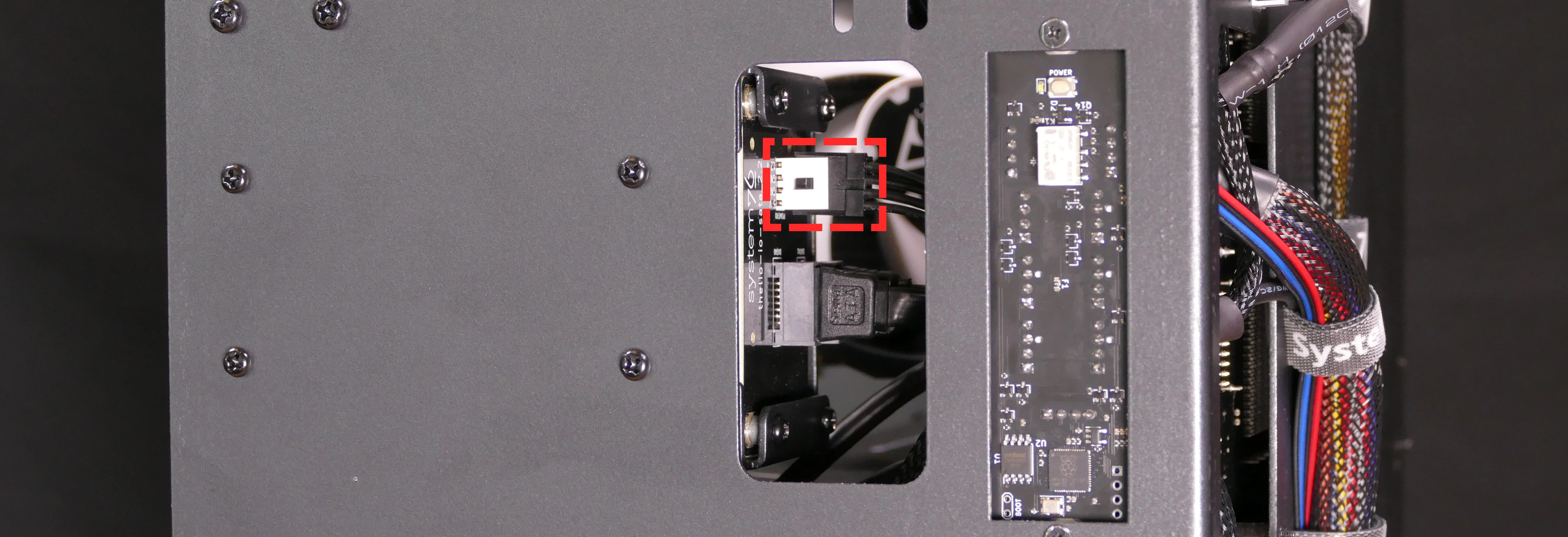
POWER1/POWER INPUT- to the power supply.- The white plastic backing needs to be held away from the connector to unplug this cable from the Thelio Io board.
PFP1/FRONT PANEL- to the power button receptacle on the front panel.- On the Thelio Io board, the wire color order (from top to bottom) is red, black, blue, black.
- On the power button receptacle, the wire color order (from left to right) is red, black, blue, black.
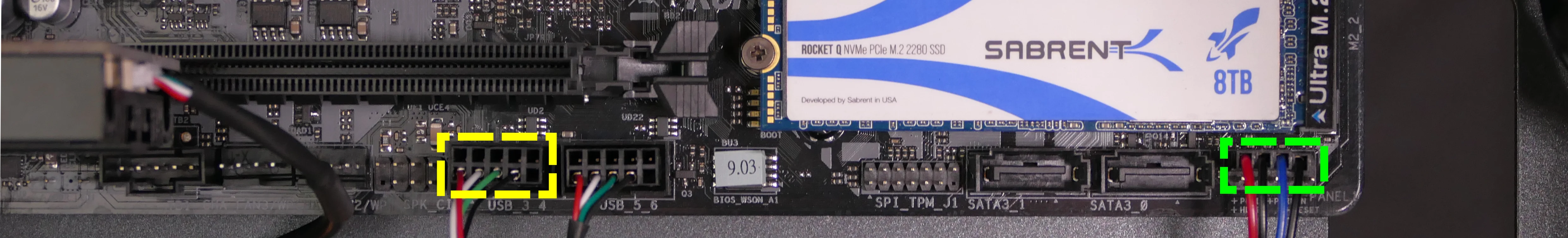
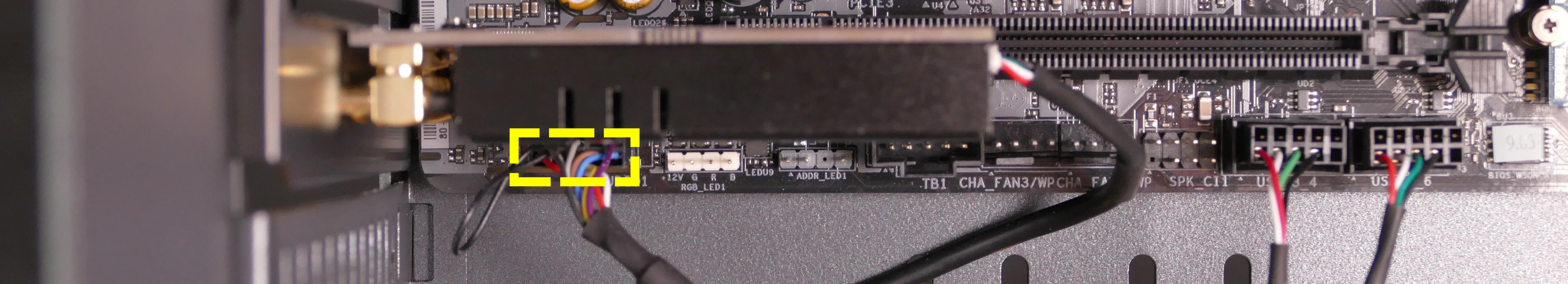
PMB1/MOTHERBOARD- to thePANEL1header at the bottom right of the motherboard, highlighted green below.- On the Thelio Io board, the wire color order (from top to bottom) is red, black, blue, black.
- On the motherboard, the wire color order (from left to right) is red, black, blue, black.
USB- to theUSB_3_4header on the bottom edge of the motherboard, highlighted yellow below.- A small clip needs to be held down to unplug this cable from the Thelio Io board.
- This port can alternatively be connected to the
USB_5_6header if theUSB_3_4header is connected to the wireless card.
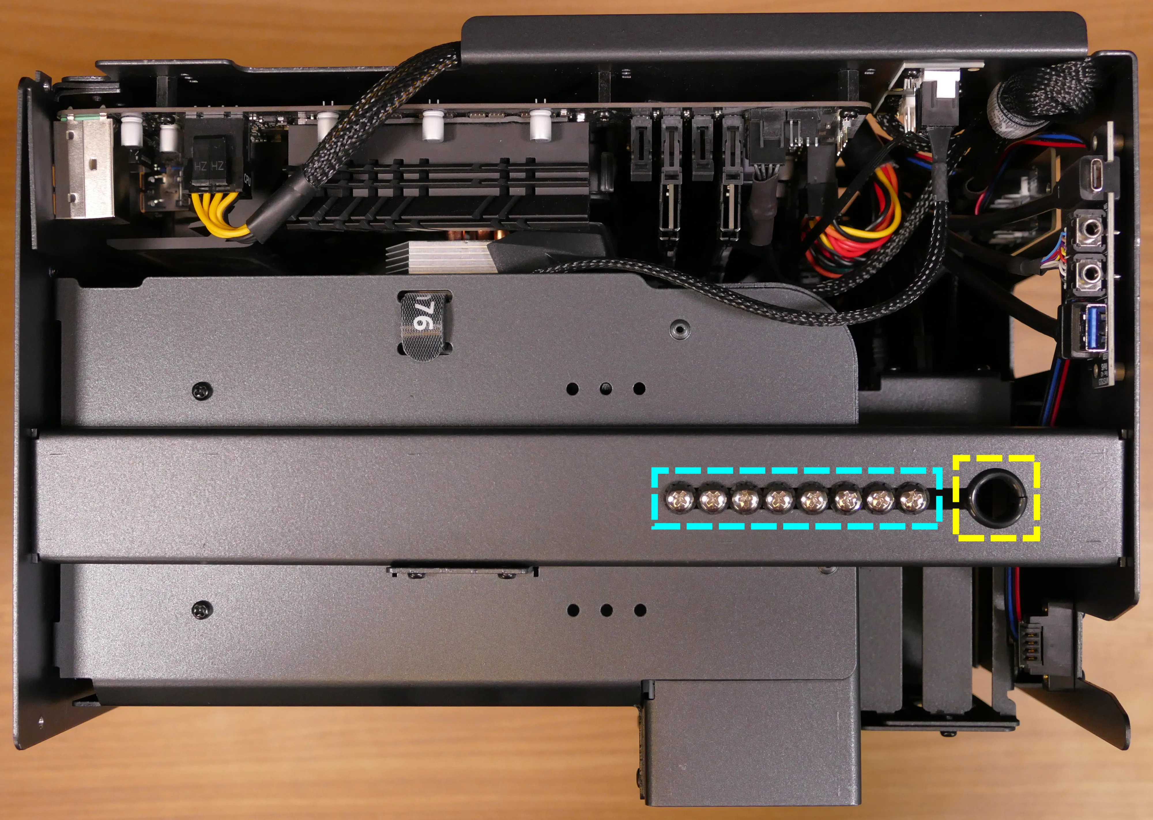
Replacing the SATA backplane:
The SATA backplane provides two 2.5“ SATA data and power connectors for the 2.5“ drive cage. The part number and version for the SATA backplane is thelio-io-sata_2.2.
Tools required: Cross-head (Phillips) screwdriver
Time estimate: 30 minutes
Difficulty: Medium ●
Steps to replace the SATA backplane:
- Follow the steps above to remove the top case, then remove the 2.5“ drive cage cover and all 2.5“ SATA drives.
- The CPU duct can optionally be removed to provide easier access to the cabling.
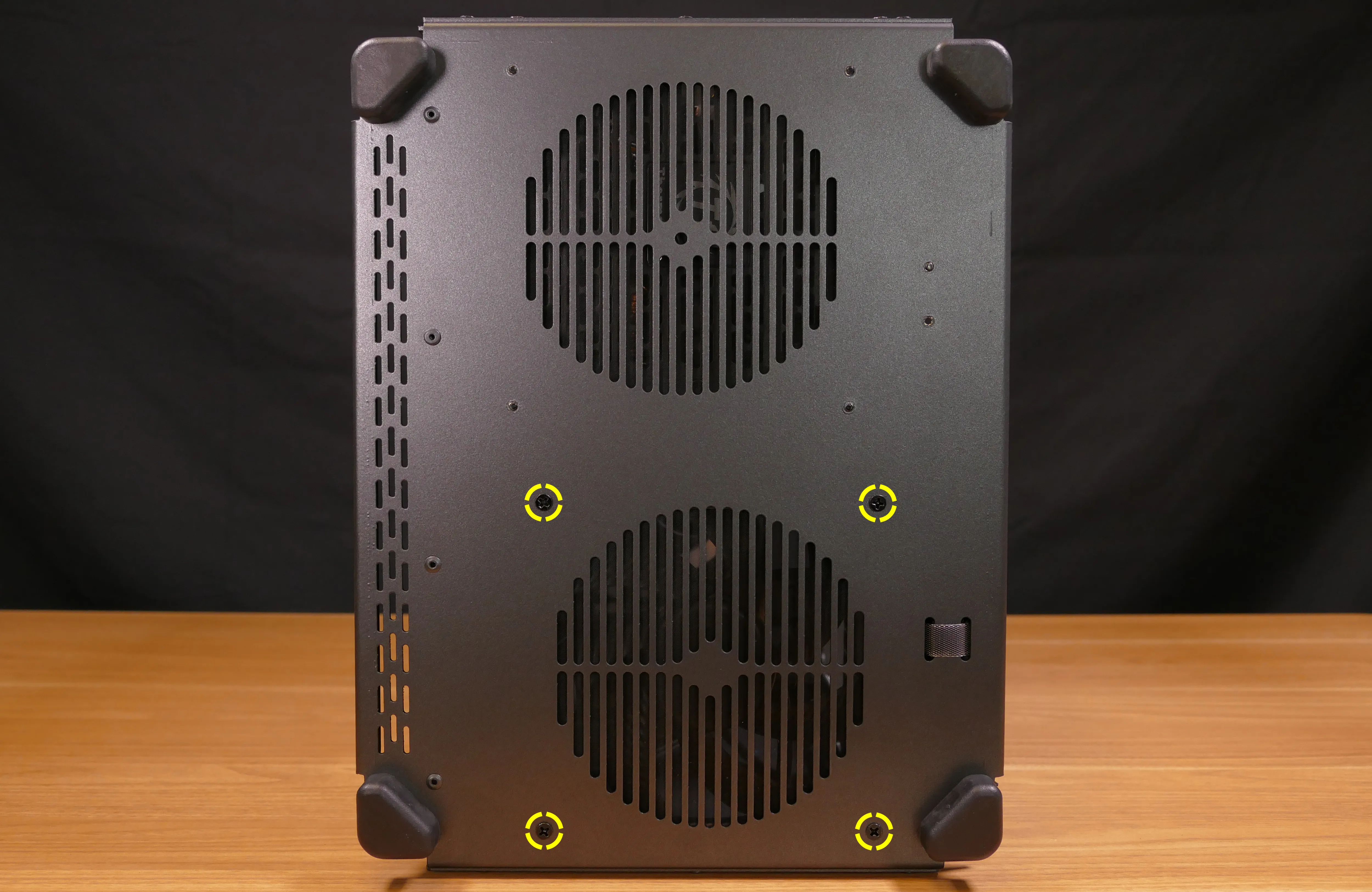
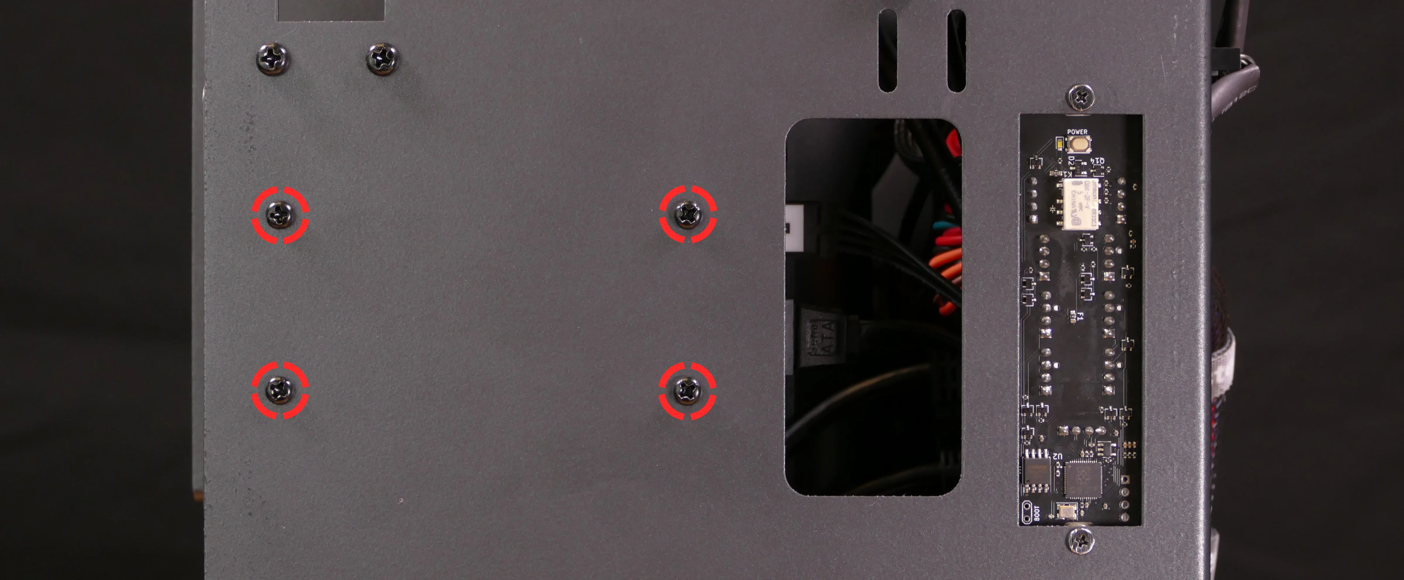
- Use the cutouts on the front right corner of the chassis to unplug the 4-pin Berg power connector (highlighted cyan below) and the two SATA data cables (highlighted green below) from the SATA backplane.
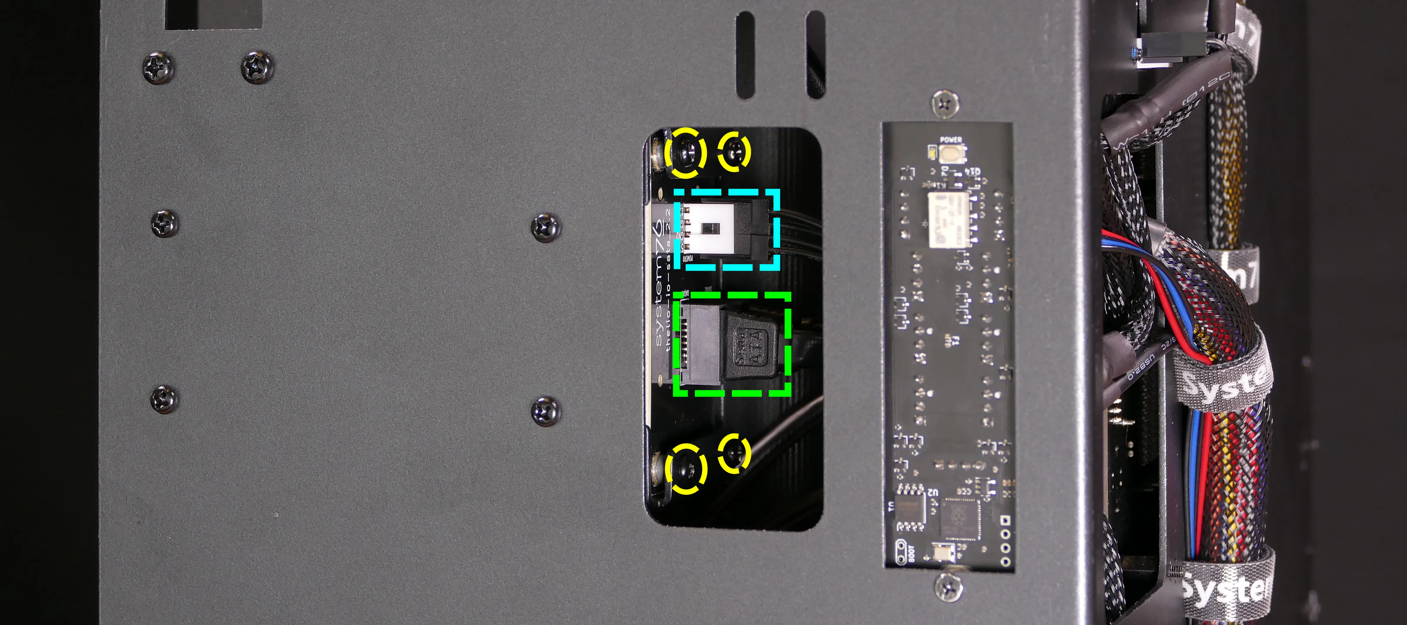
- Unscrew the four screws holding the drive cage onto the chassis (highlighted red above), then remove the drive cage from the chassis.
- This step is optional if you can remove the four SATA backplane screws (highlighted yellow above and below) from the drive cage without removing it from the chassis. The Thelio Io cabling partially obstructs the screws, so removing the cage is suggested.
- Unscrew the four SATA backplane screws from the drive cage, then push the SATA backplane out through the front of the drive cage.
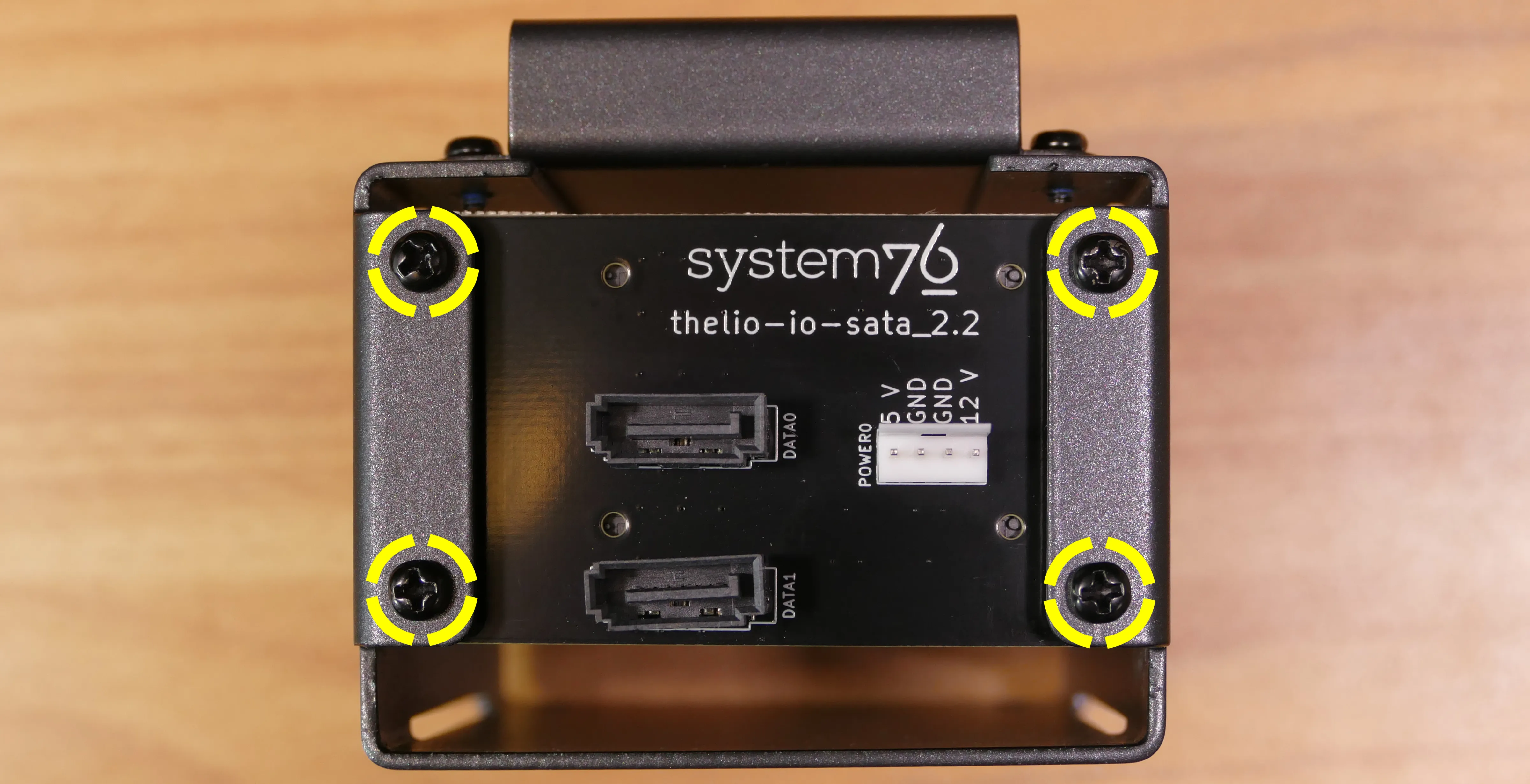
- Place the new SATA backplane into the drive cage and secure it with the four SATA backplane screws, then reinstall the drive cage (if necessary).
- Plug the 4-pin Berg power connector and SATA data cables into the SATA backplane.
- The order of the SATA data cables shouldn’t matter as long as your operating system and software is configured to address disks by UUID (e.g.
/dev/disk/by-id/...) instead of by letter (e.g./dev/sd_). - By default, the
DATA1port connects to the innermost SATA connector on the motherboard, and theDATA0port connects to the outermost SATA connector on the motherboard.
- The order of the SATA data cables shouldn’t matter as long as your operating system and software is configured to address disks by UUID (e.g.
- Reinstall the CPU shroud (if necessary), any 2.5“ drives that were removed, the 2.5“ drive cage cover, and the top case.
Replacing the top I/O:
Thelio Spark B1-N2 includes a top I/O module providing audio and USB ports. This module’s part number is MYS7523 Rev. 4.0.
If the top ports are damanged or become defective, they can be replaced using the steps below.
Tools required: Cross-head (Phillips) screwdriver
Time estimate: 30 minutes
Difficulty: Medium ●
Steps to replace the top I/O:
- Follow the steps above to remove the top case and remove the CPU duct.
- You can optionally remove the side brace for easier access to the wiring.
- Unplug the
HD_AUDIO1header at the bottom-left corner of the motherboard, below the wireless card.
- Unplug the
F_USB3_5_6header (highlighted cyan below) andF_USB3_TC_1header (highlighted green below) along the right edge of the motherboard, between the RAM and the 2.5“ drive cage.
- Unscrew the two front screws holding the top I/O board onto the chassis.
- Remove the top I/O board from the system.
- Insert the new top I/O board into the system and screw it into place.
- Reconnect the audio and USB headers.
- Replace the side brace (if necessary), CPU shroud, and top case.
Troubleshooting the power button:
If the front power button doesn’t power the machine on or doesn’t light up when the system is powered on, try the following troubleshooting steps:
- Ensure the system powers on normally using the internal power button.
- Reseat the front power button to ensure it’s making proper contact.
- Check the wiring for the front power button.
- Replace the front power button, if necessary.
Tools required: Cross-head (Phillips) screwdriver (optional)
Time estimate: 20 minutes
Difficulty: Medium ●
Steps to power the machine on using the internal power button:
- Follow the steps above to remove the top case.
- Ensure the system is plugged into power, and the power supply switch is in the 1 (On) position.
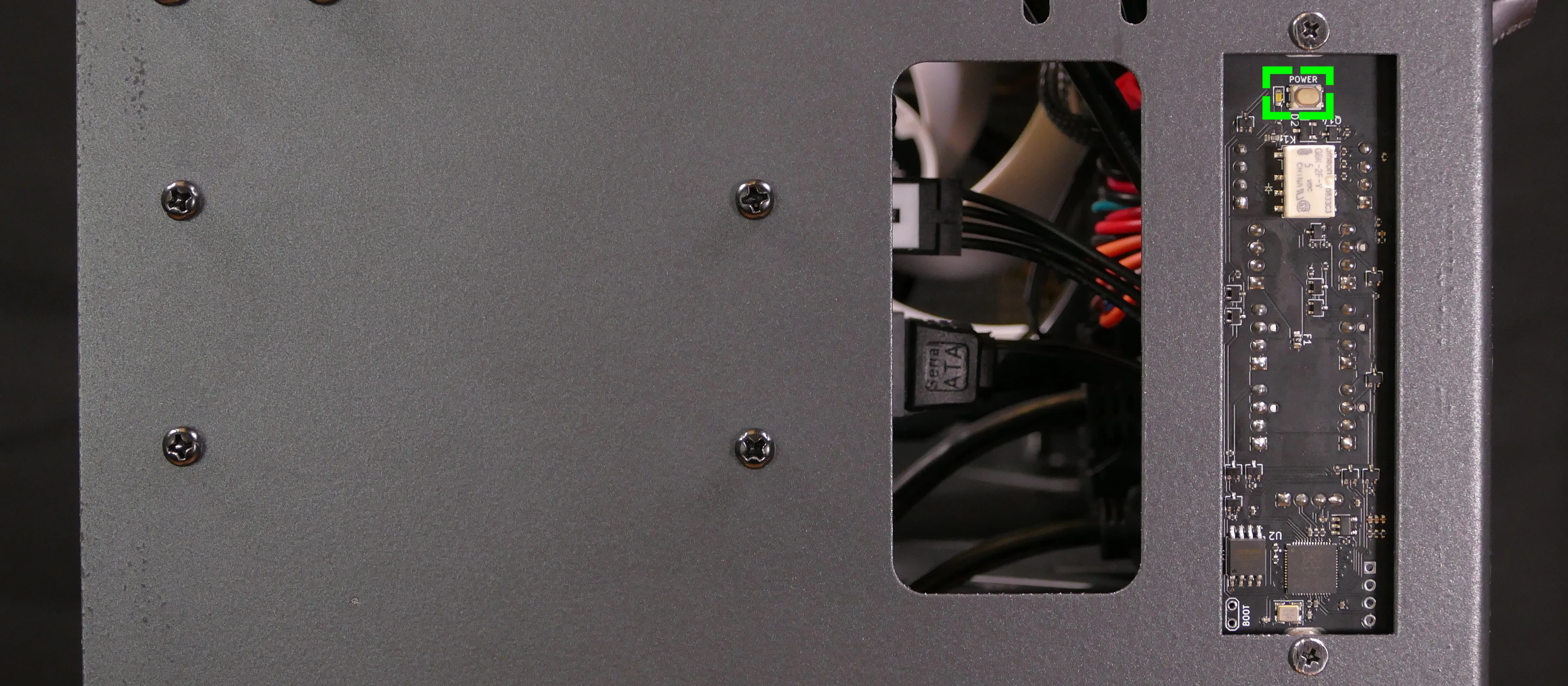
- Push the small button labeled
POWERon the Thelio Io board.- The white LED to the left of the button lights up to indicate when the system is powered on (and pulses when the system is suspended).
- If the Thelio Io
POWERbutton powers the machine on and the LED lights up, then the issue is either the front power button or its connection to the Thelio Io board. Check the front power button wiring. - If the Thelio Io
POWERbutton and/or LED does not work, then the issue is either the Thelio Io board or its connection to the motherboard. Check the wiring between the Thelio Io board and the motherboard.
Steps to check the front power button wiring:
- Follow the steps above to remove the top case.
- On the back of the power button, the four pins should be connected to the four-wire connector as follows:
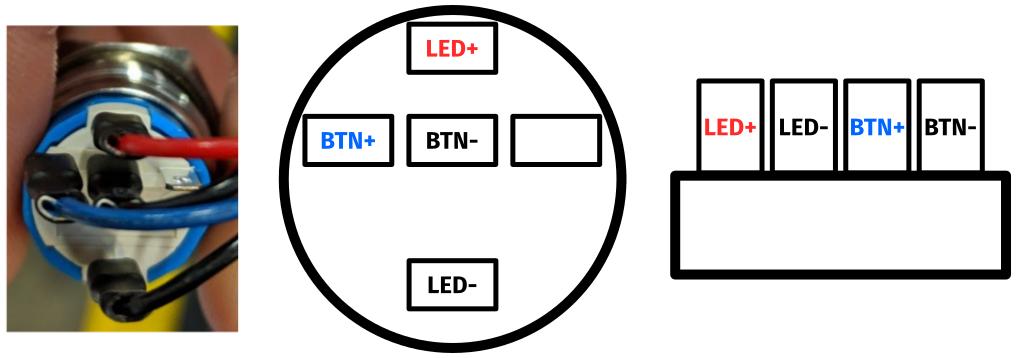
- On the front power button receptacle, the four-pin connector should have the red wire on the left and the black wire on the right (when viewed from the back of the computer.)
- If necessary, you can remove the 2.5“ drive cage for easier access to the power button receptacle’s connector.
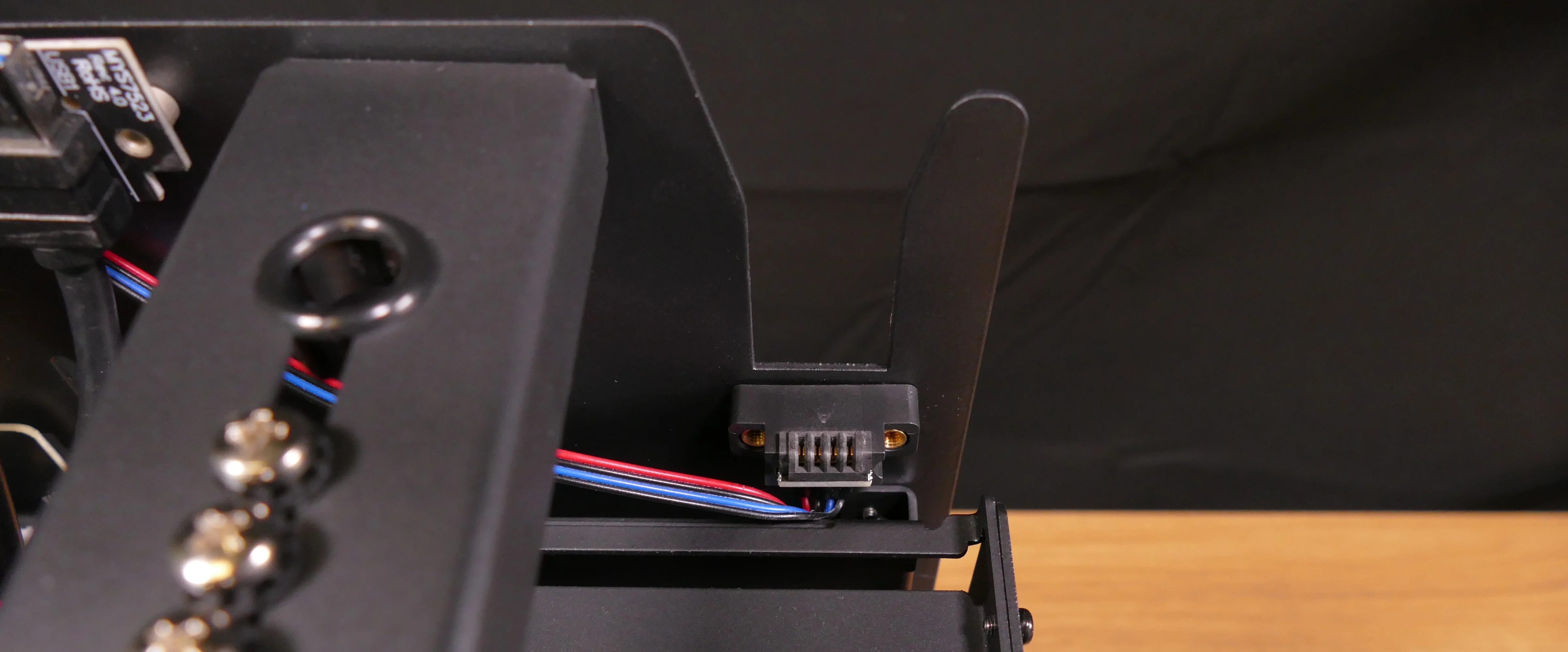
- The front power button receptacle should plug into the
PFP1port on the Thelio Io board, with the red wire on the top (see the Thelio Io wiring guide.)
Steps to replace the power button:
- Follow the steps above to remove the top case.
- Follow the instructions in the Replace the Thelio Power Button support article.