Thelio Mira (Parts & Repairs)
Many components in your Thelio Mira can be upgraded or replaced as necessary. This page uses photos of the initial revision for this generation (R3-0). Minor case details may vary on newer units, but screw counts, general component locations, and other details should remain the same unless otherwise noted.
Power the machine off, switch off the power supply, and unplug all peripherals before working with any internal components. Then, follow these step-by-step guides for instructions:
- Replacing the front accent strip
- Removing the top case
- Adding/removing 2.5“ storage drives
- Replacing the bottom case fan
- Replacing the GPU
- Removing the CPU duct
- Replacing the RAM
- Replacing the M.2 drives
- Replacing the CPU fans
- Replacing the CPU cooler/thermal paste and CPU
- Replacing the power supply
- Replacing the Thelio-IO board
- Troubleshooting the power button
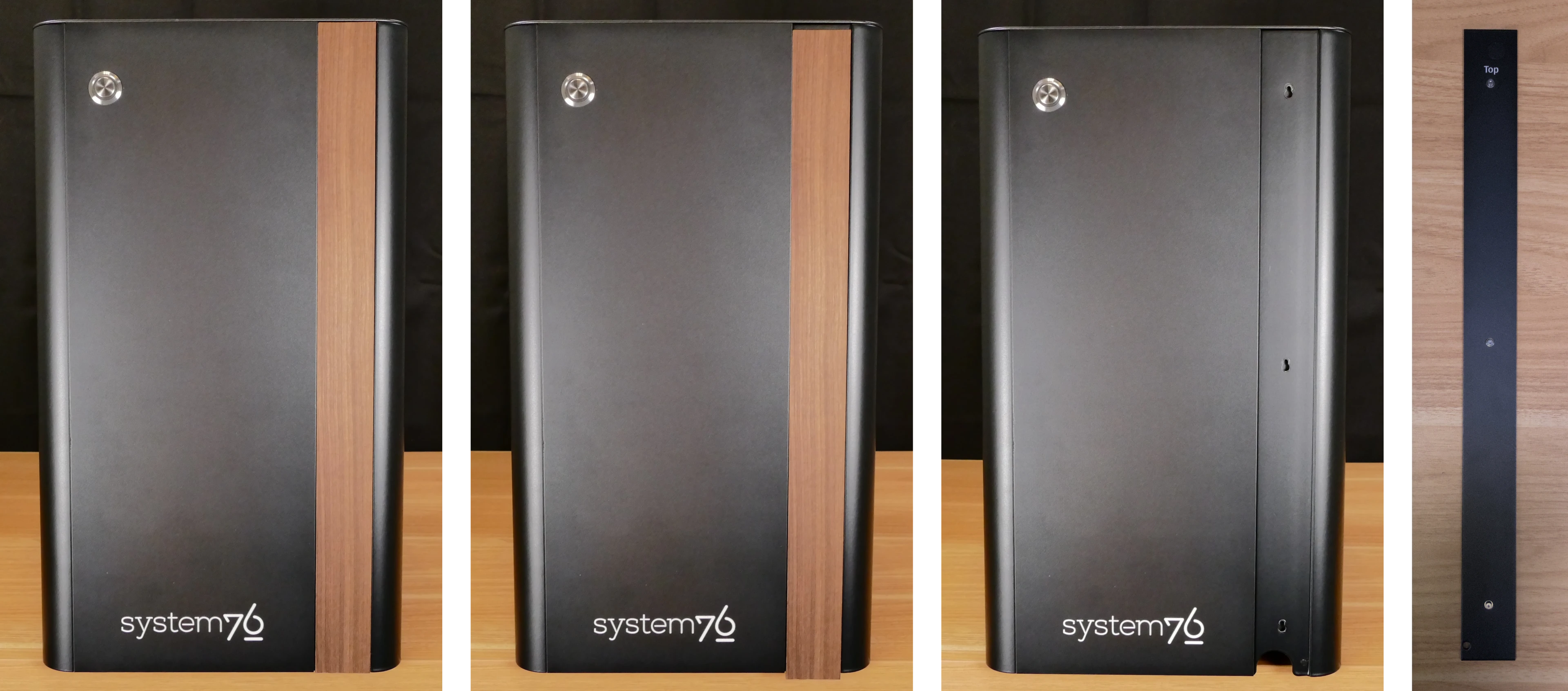
Replacing the front accent strip:
Thelio Mira includes a customizable accent panel on the front of the case, which can be swapped to change the case’s look and feel. The instructions for swapping the accent are also available in video form.
Tools required: None
Time estimate: 30 seconds
Difficulty: Easy ●
Steps to replace the front accent strip:
- Place the Thelio on the edge of the desk so the front side is hanging off of the desk.
- The Thelio can alternatively be lifted or tilted so the front of the computer is hovering above the desk.
- Slide the accent strip down to unlock it.
- The accent can be gripped at the bottom edge.
- Pull the accent strip off of the case, starting with the bottom edge.
- Place the new accent strip onto the front of the case and slide it up to lock it into place.
Removing the top case:
The top case can be removed to access the internal components.
Tools required: Cross-head (Phillips) screwdriver (optional)
Time estimate: 2 minutes
Difficulty: Easy ●
Steps to remove the top case:
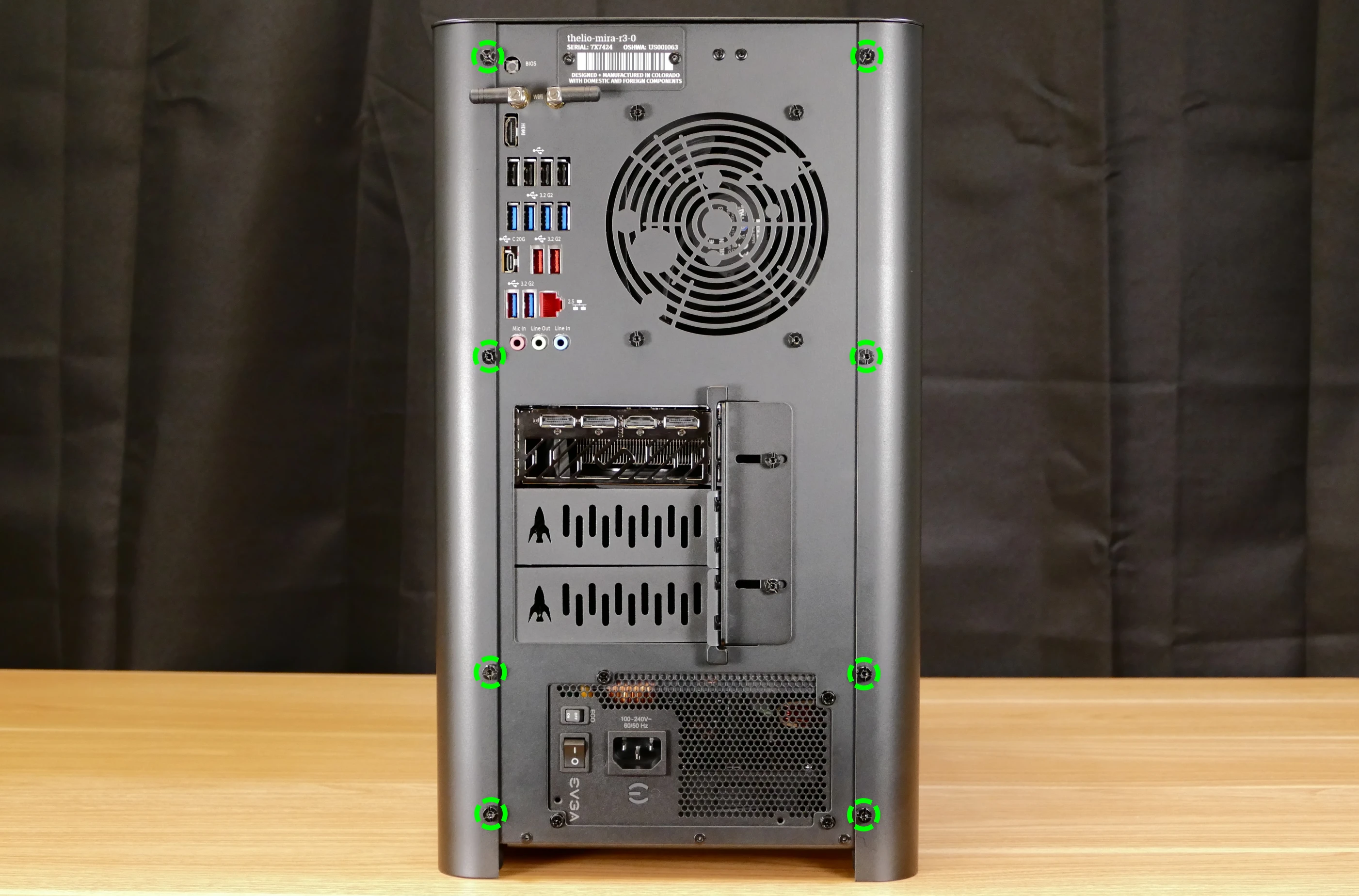
- Remove the eight outer screws holding the top case onto the machine.
- Slide the top case up and off of the machine.
Adding/removing 2.5“ storage drives:
Thelio Mira R3 supports up to four 2.5“ SATA III drives.
Tools required: Cross-head (Phillips) screwdriver (optional)
Time estimate: 7 minutes
Difficulty: Easy ●
Steps to add/remove 2.5“ storage drives:
- Follow the steps above to remove the top case.
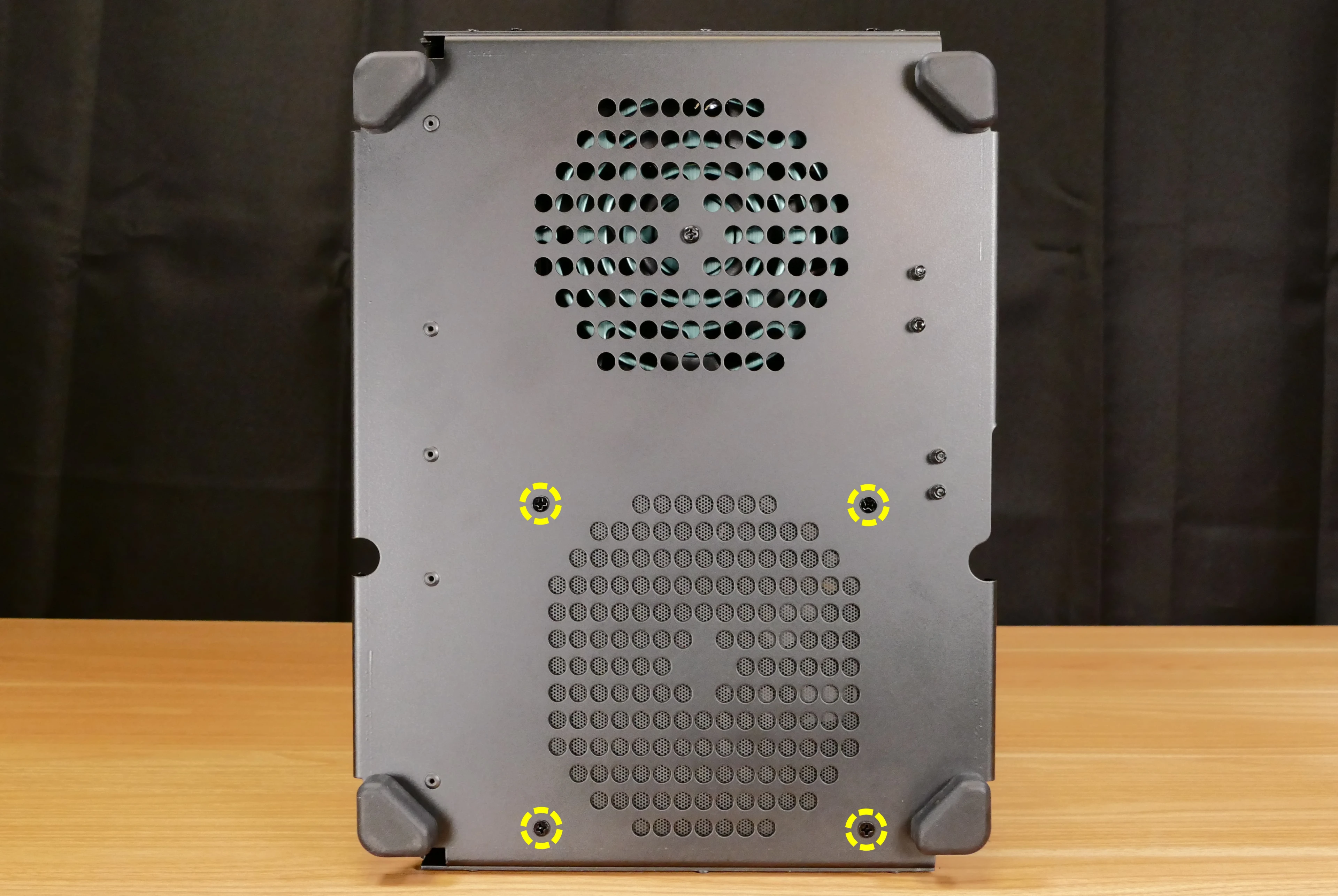
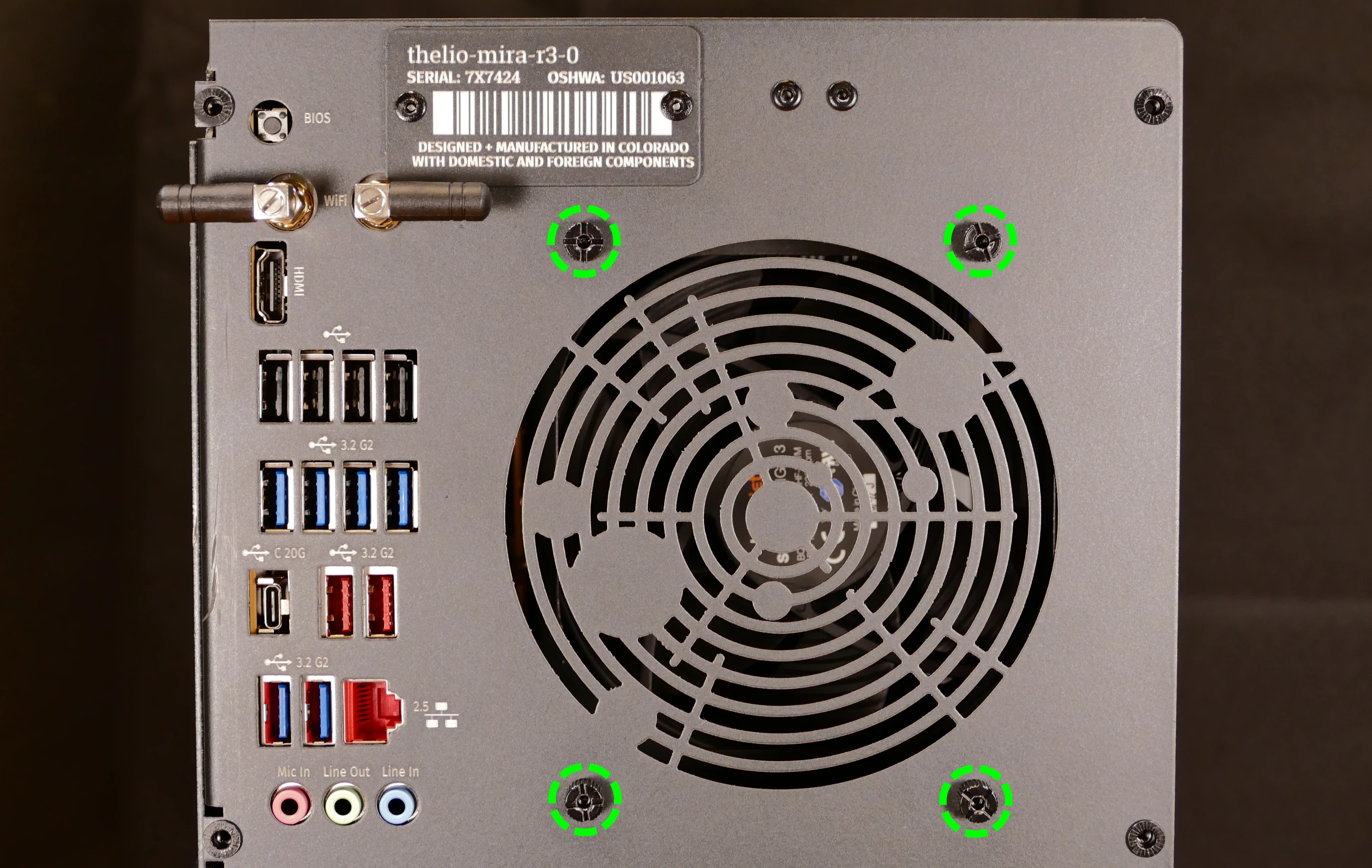
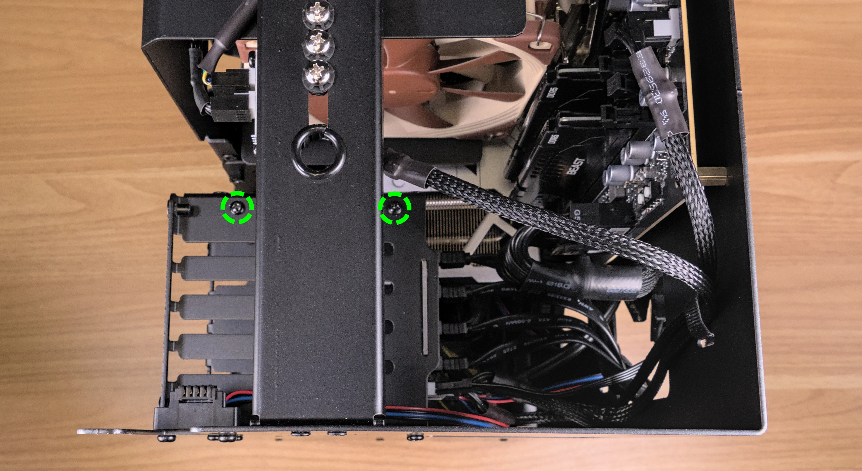
- Unscrew the two screws securing the drive bay’s cover, highlighted green below.

- If you are adding a new drive, pop out the black plastic ring on the top crossbar and slide out four screws (per drive).
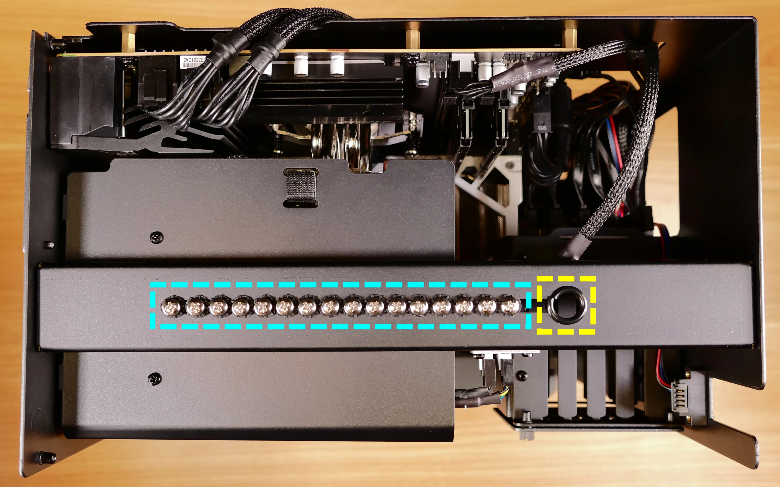
- Insert four screws into each 2.5“ storage drive you wish to install.
- Slide each 2.5“ drive into one of the slots leading to the Thelio-IO board.
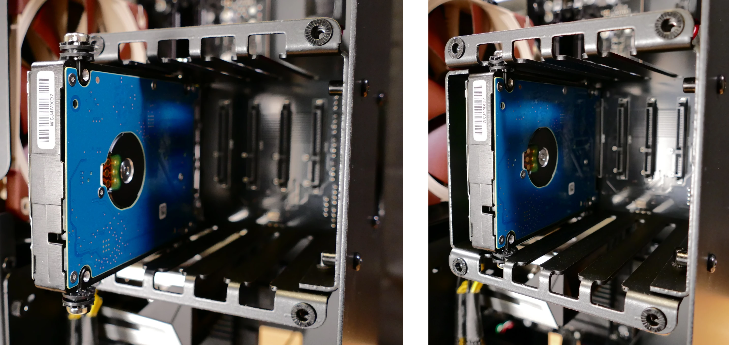
Thelio Mira R3 with one 2.5“ drive installed.
- Replace the black plastic screw ring and the 2.5“ drive bay cover.
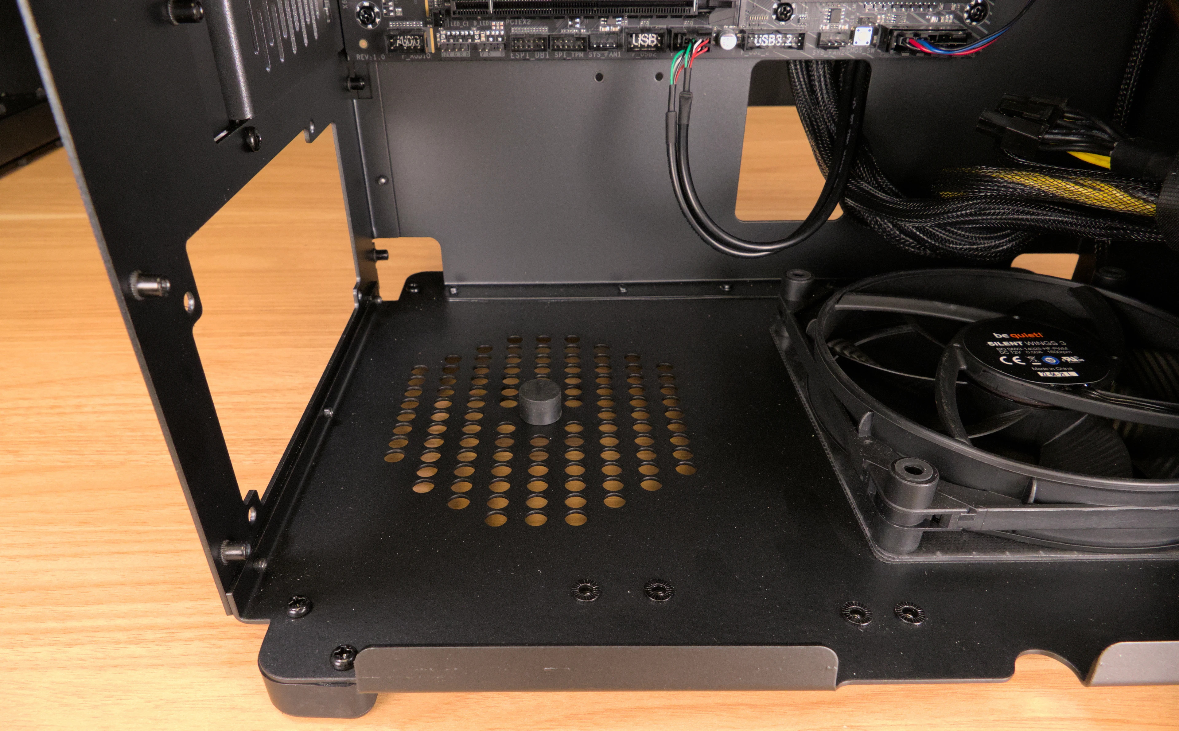
Replacing the bottom case fan:
Thelio Mira R3 has one case-mounted intake fan on the bottom of the chassis.
Tools required: Cross-head (Phillips) screwdriver
Time estimate: 20 minutes
Difficulty: Medium ●
Steps to replace the bottom case fan:
- Follow the steps above to remove the top case.
- Unplug the fan’s cable from the Thelio-IO daughterboard.
- The bottom case fan plugs into the
INTAKE0port on the Thelio-IO board. - When viewed from the front of the case, this connector is second from the top.
- The bottom case fan plugs into the
- Unscrew the four fan screws from the bottom of the machine.
- To avoid damaging other components, place the machine on its front side when working with the bottom surface.
- Remove the old fan from the case.
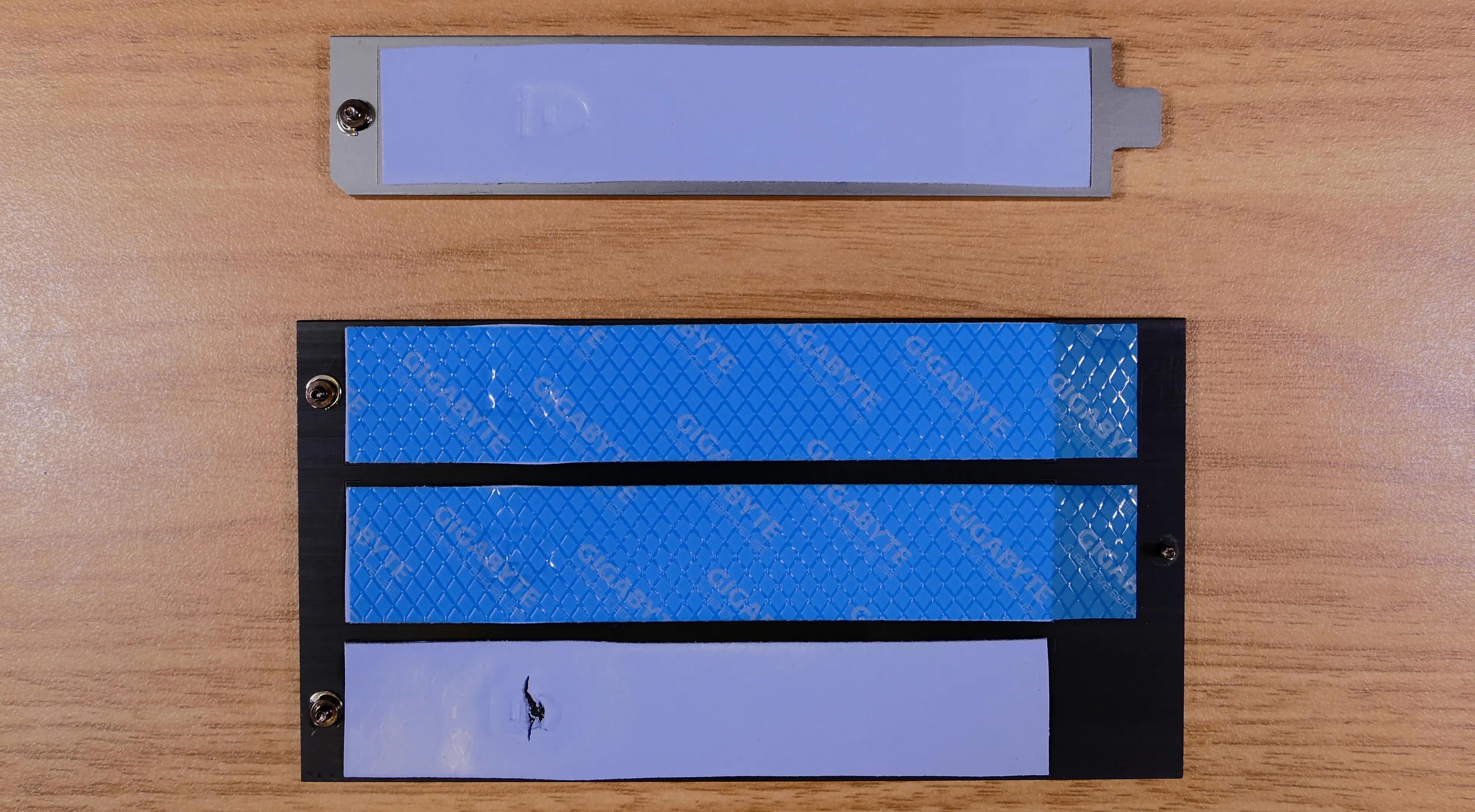
- When installing the fan, mount the components in the following order:
- Chassis
- Dust filter
- Acrylic spacer
- Fan
- The new fan’s cable should be oriented towards the front-right corner of the case.
- The cable runs along the inner corner of the case, and does not pass through any of the cable management holes or velcro strips.
Replacing the GPU:
Thelio Mira supports two multi-slot dedicated GPUs:
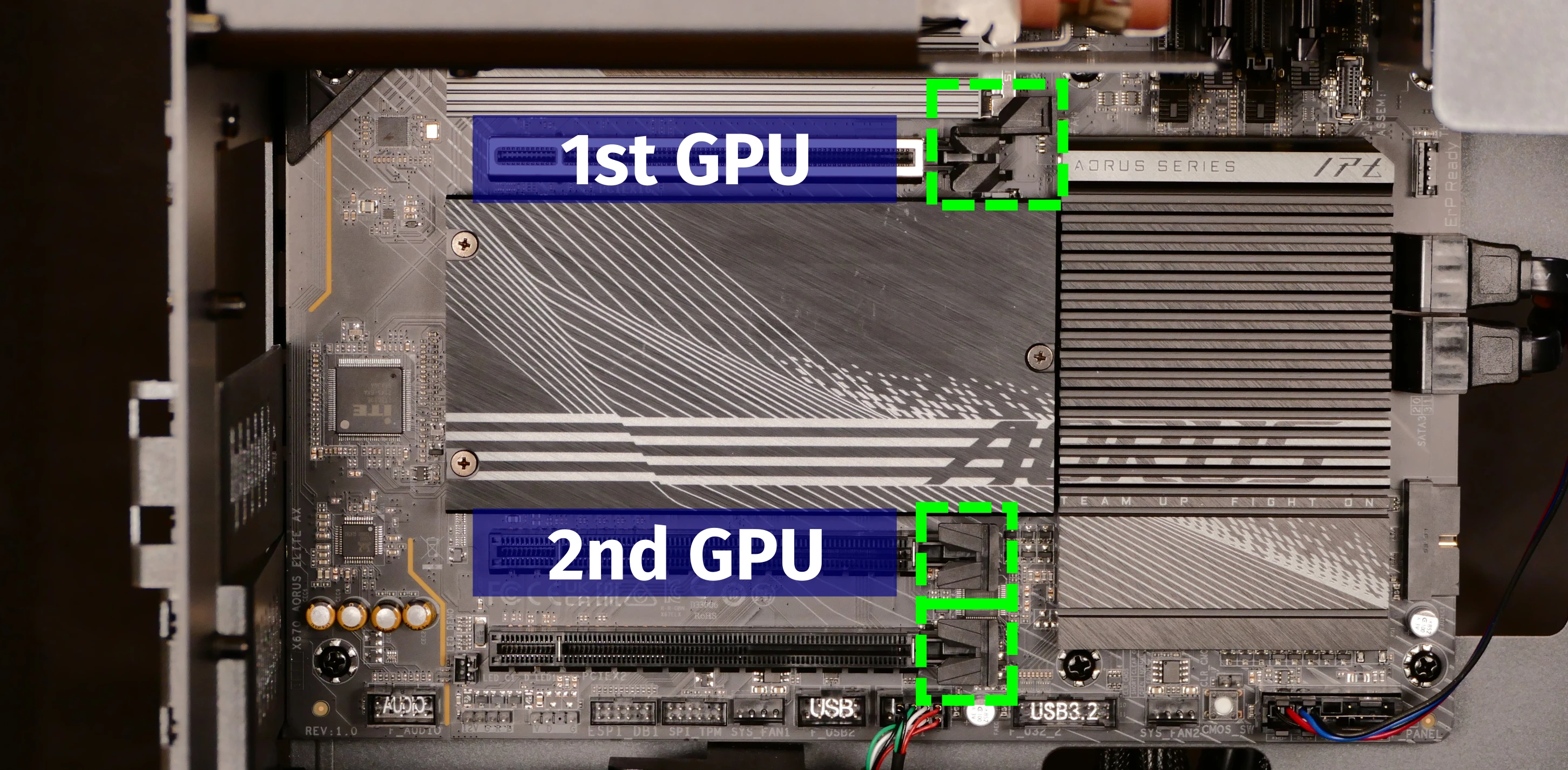
- The top GPU slot is a PCIe 4.0 x16 slot.
- There are four units of clearance in the back of the chassis.
- The bottom GPU slot is a PCIe 4.0 x4 slot.
- There are two units of clearance in the back of the chassis.
- This slot is forwards-compatible with x16 cards.
Factory configurations only include one GPU.
Tools required: Cross-head (Phillips) screwdriver
Time estimate: 15 minutes
Difficulty: Medium ●
Steps to replace the GPU:
- Follow the steps above to remove the top case.
- Unscrew the two back screws holding the PCIe bracket in place, and remove the PCIe bracket.
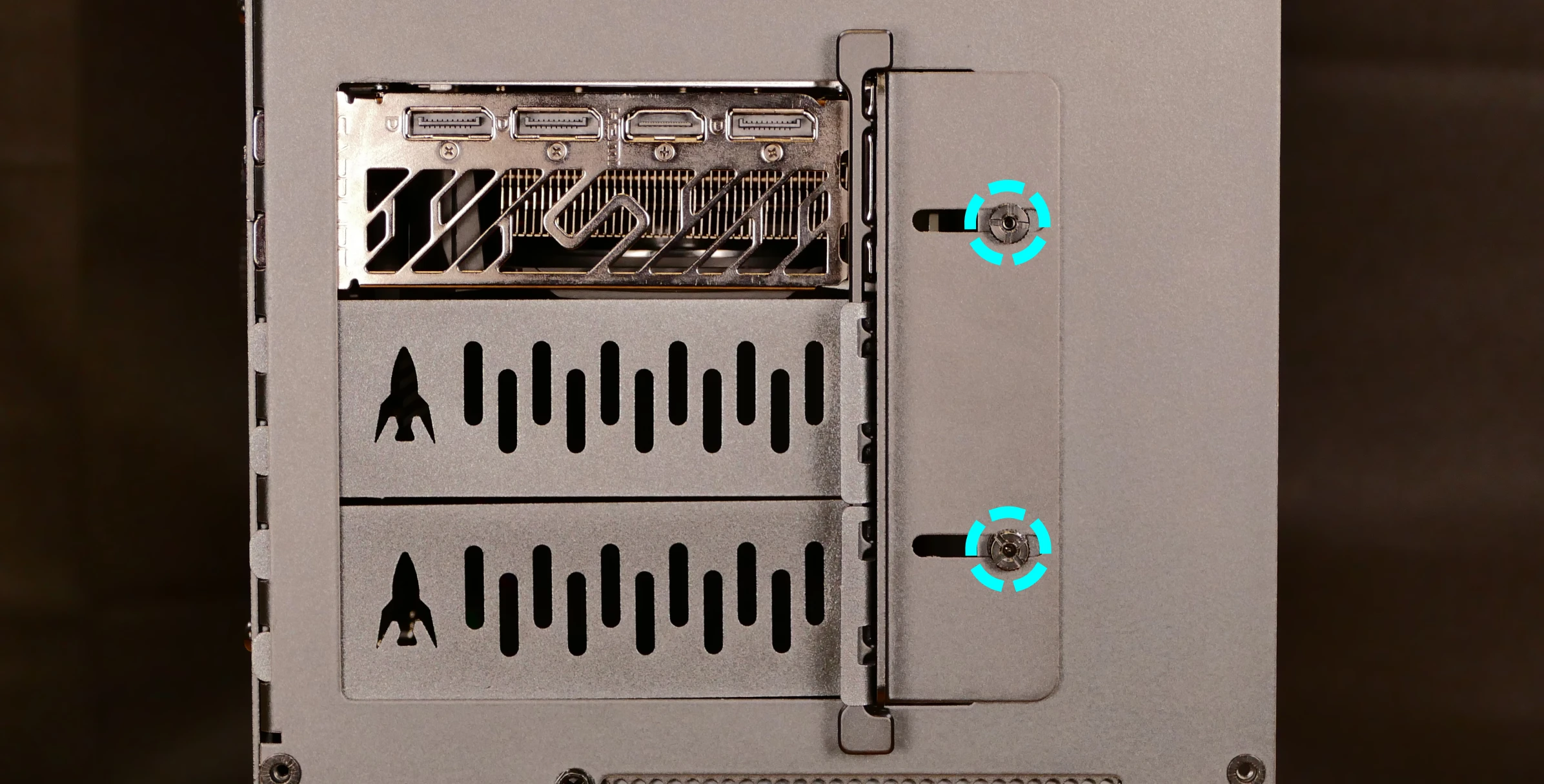
- Unscrew the four screws holding the side GPU brace in place. Remove the brace.
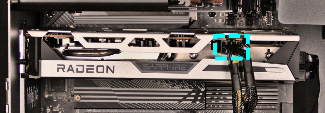
- If you’re removing a GPU, unplug the GPU power cable from the right side of the card. Hold down the latch on the connector while unplugging the cable.
- Push and hold the latch on the motherboard to free the PCIe connection, then pull the card out of the slot.
- After inserting the new GPU into its slot, connect the power cable.
- Once the GPU is installed, replace the side GPU brace, back PCIe bracket, and top case.
- The side GPU brace includes screws to adjust for the height and depth of the graphics cards.
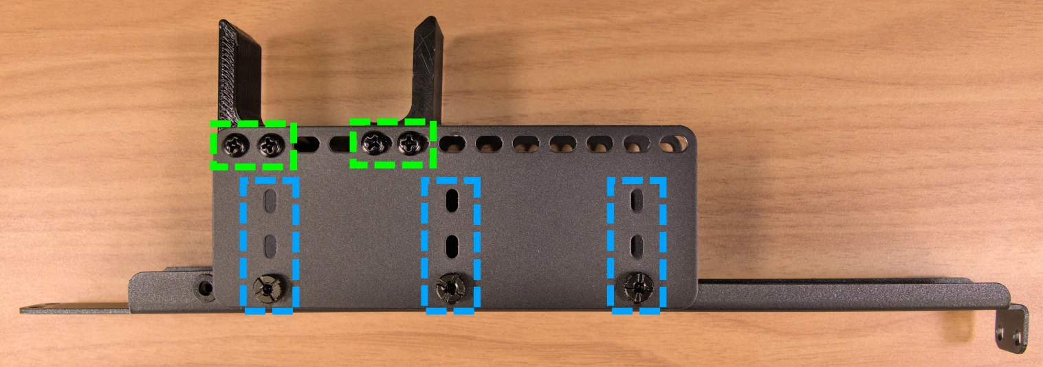
The GPU brace’s primary function is to prevent damage during shipping. The system can be run without the brace if it doesn’t fit an upgraded card; the back PCIe bracket provides primary support for the GPU.
Removing the CPU duct:
The CPU duct guides airflow through the CPU cooler. It covers the CPU and partially obstructs the RAM slots and top GPU.
Tools required: Cross-head (Phillips) screwdriver
Time estimate: 7 minutes
Difficulty: Easy ●
Steps to remove the CPU duct:
- Follow the steps above to remove the top case and remove the GPU brace.
- The GPU can also optionally be removed to provide more room for working with the components.
- Unplug the connectors for the CPU fans from the splitter board on the top crossbar.
- The splitter board provides the same signal to both ports, so it doesn’t matter which fan is plugged into which port.
- Unscrew the four back screws holding the CPU duct in place.
- Pull the CPU duct away from the machine.
Replacing the RAM:
Thelio Mira R3 supports up to 128GB (4x32GB) of RAM. The RAM sticks are DDR5 DIMMs (non-ECC) running at a speed of up to 4800MHz (the maximum 4x32GB configuration is limited to 3600MHz). If you’ve purchased new RAM, need to replace your RAM, or are reseating your RAM, follow these steps.
Tools required: Cross-head (Phillips) screwdriver
Time estimate: 15 minutes
Difficulty: Medium ●
Steps to replace the RAM:
- Follow the steps above to remove the top case and remove the CPU duct.
- Removing the CPU duct is optional, but is recommended to provide easier access to the leftmost RAM slot.
- To remove an existing RAM stick, flip the top and bottom latches away from the stick, then pull the stick out of the slot.
- Make sure the tabs on the top and bottom of the slot are open (pulled away from the slot), then insert the new RAM (or re-seat the existing RAM) into the slot.
- The RAM stick will only fit in one direction. The larger group of pins goes on top.
- Use the following guide for placement of the RAM sticks:
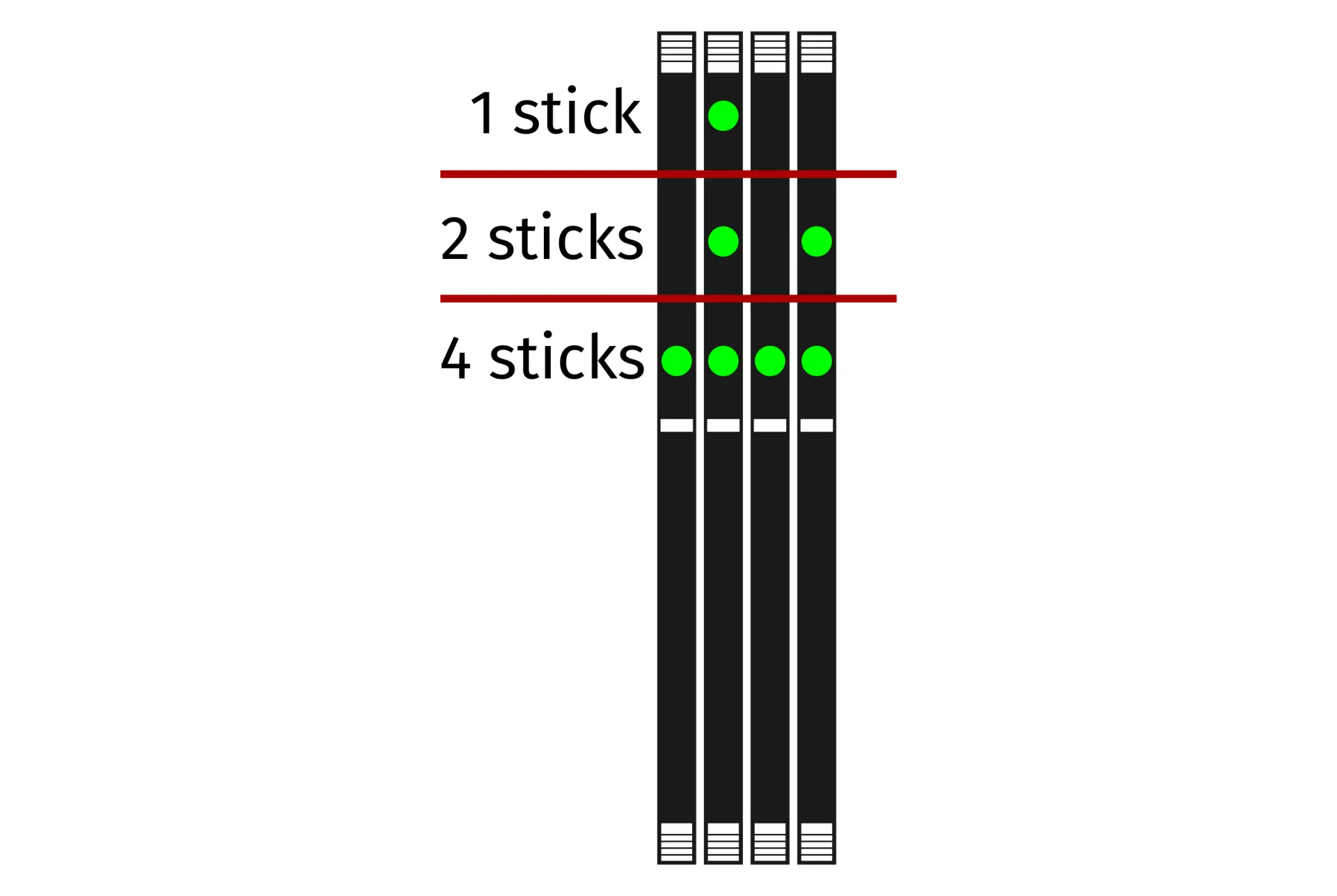
- Replace the top case.
Replacing the M.2 drives:
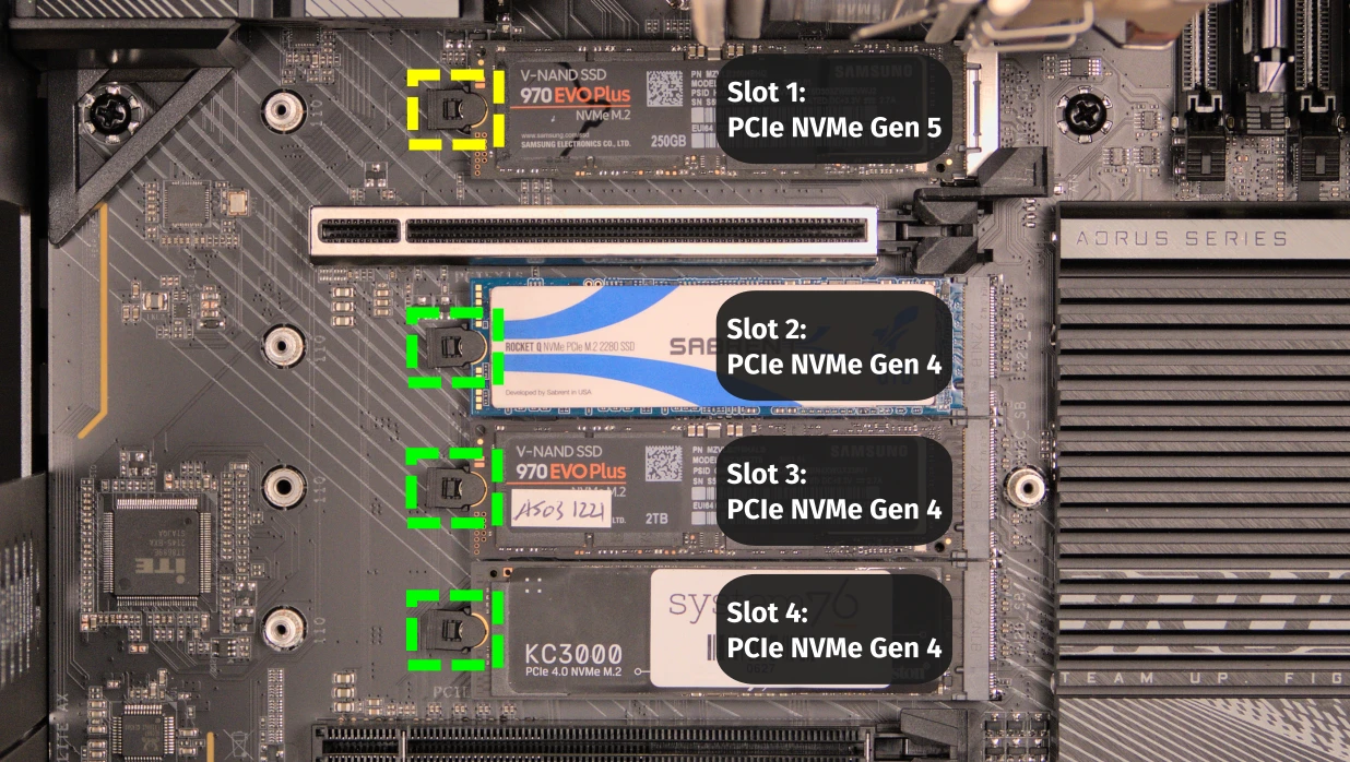
Thelio Mira R3 has four M.2 storage slots. All four slots are M key and size 2280.
- Slot 1 supports PCIe NVMe Gen 5.
- Slots 2, 3, and 4 support PCIe NVMe Gen 4.
Tools required: Cross-head (Phillips) screwdriver
Time estimate: 30 minutes
Difficulty: Medium ●
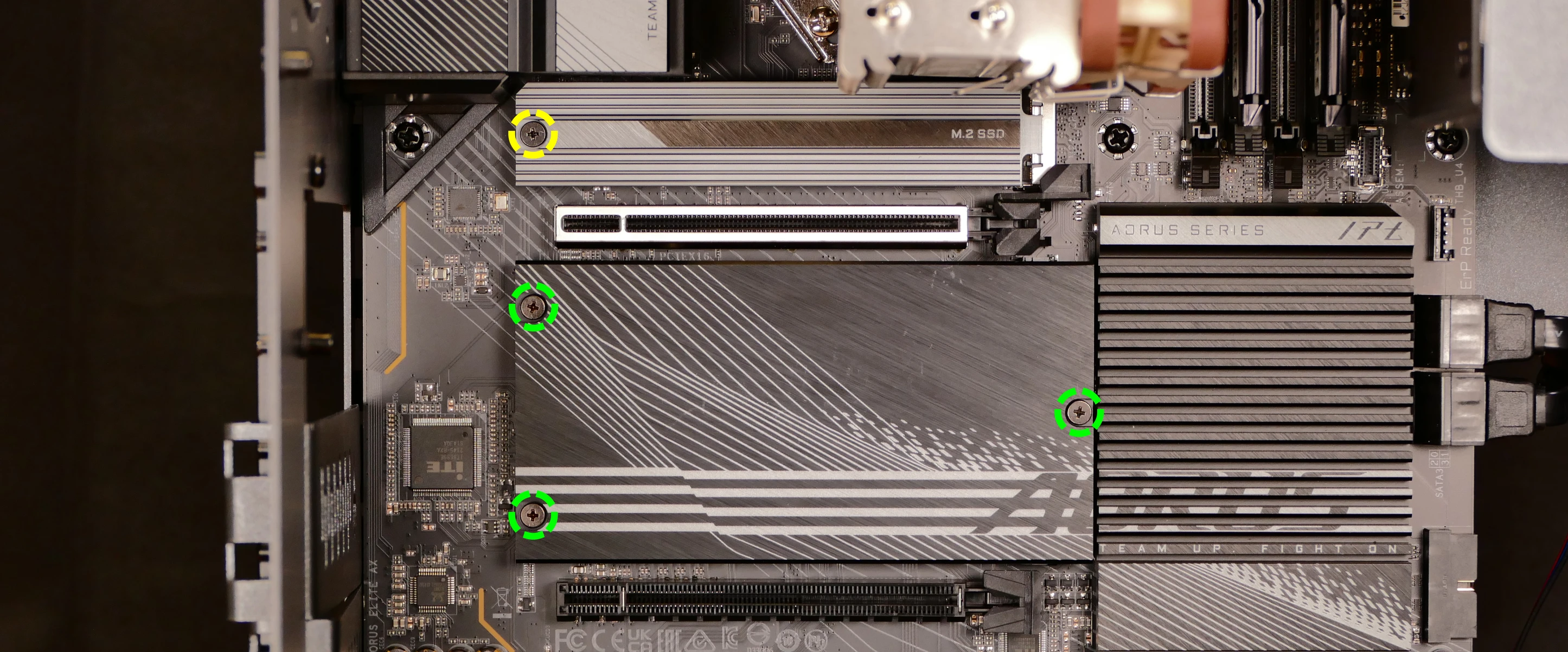
Steps to replace the M.2 drive:
- Follow the steps above to remove the top case.
- Unscrew and remove the M.2 heatsink.
- Slot 1 is located underneath the single-height heatsink; slots 2, 3, and 4 are located underneath the triple-height heatsink.
- The heatsink screws are held captive, and will not fully come out of the heatsink.
- It may take some pressure to remove the heatsink and thermal tape from the M.2 drive. After unscrewing the heatsink, pull slowly to avoid breaking the thermal tape.
- For the M.2 drive(s) being removed, push the rectangular side of the retaining clip to flip it open.
- Remove the existing M.2 drive by pulling it out of the slot.
- Insert the new M.2 drive into the slot and hold it in place.
- Flip the retaining clip back into place and push the circular side until it snaps closed.
- Replace the M.2 heatsink, CPU duct, GPU, GPU brace, and top case.
- If you are populating an SSD slot for the first time, remove any protective plastic that may be covering the thermal tape.
- When installing the Slot 1 heatsink, fit the tab on the opposite end from the screw into the motherboard standoff before lining up the screw.
Replacing the CPU fans:
Thelio Mira R3 contains two CPU fans. One is mounted on the CPU duct, and one is mounted on the CPU cooler.
Tools required: Cross-head (Phillips) screwdriver
Time estimate: 25 minutes
Difficulty: Medium ●
Steps to replace the duct-mounted CPU fan:
- Follow the steps above to remove the top case, remove the GPU brace, and remove the CPU duct.
- Free the fan cable from the velcro loop, highlighted cyan below.
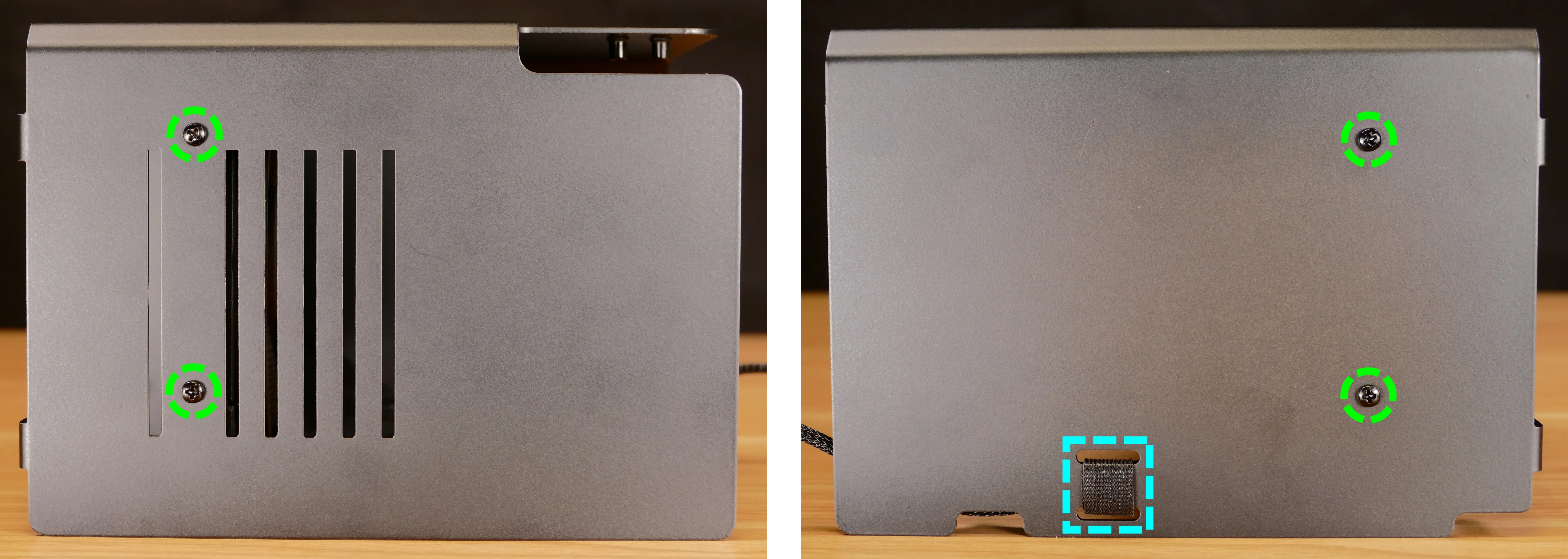
- Unscrew the four screws (two on each side) holding the fan bracket onto the duct.
- Removing the bracket from the duct is not required to remove the fan, but it makes installing the fan much easier.
- Unscrew the four screws attaching the bracket to the fan.
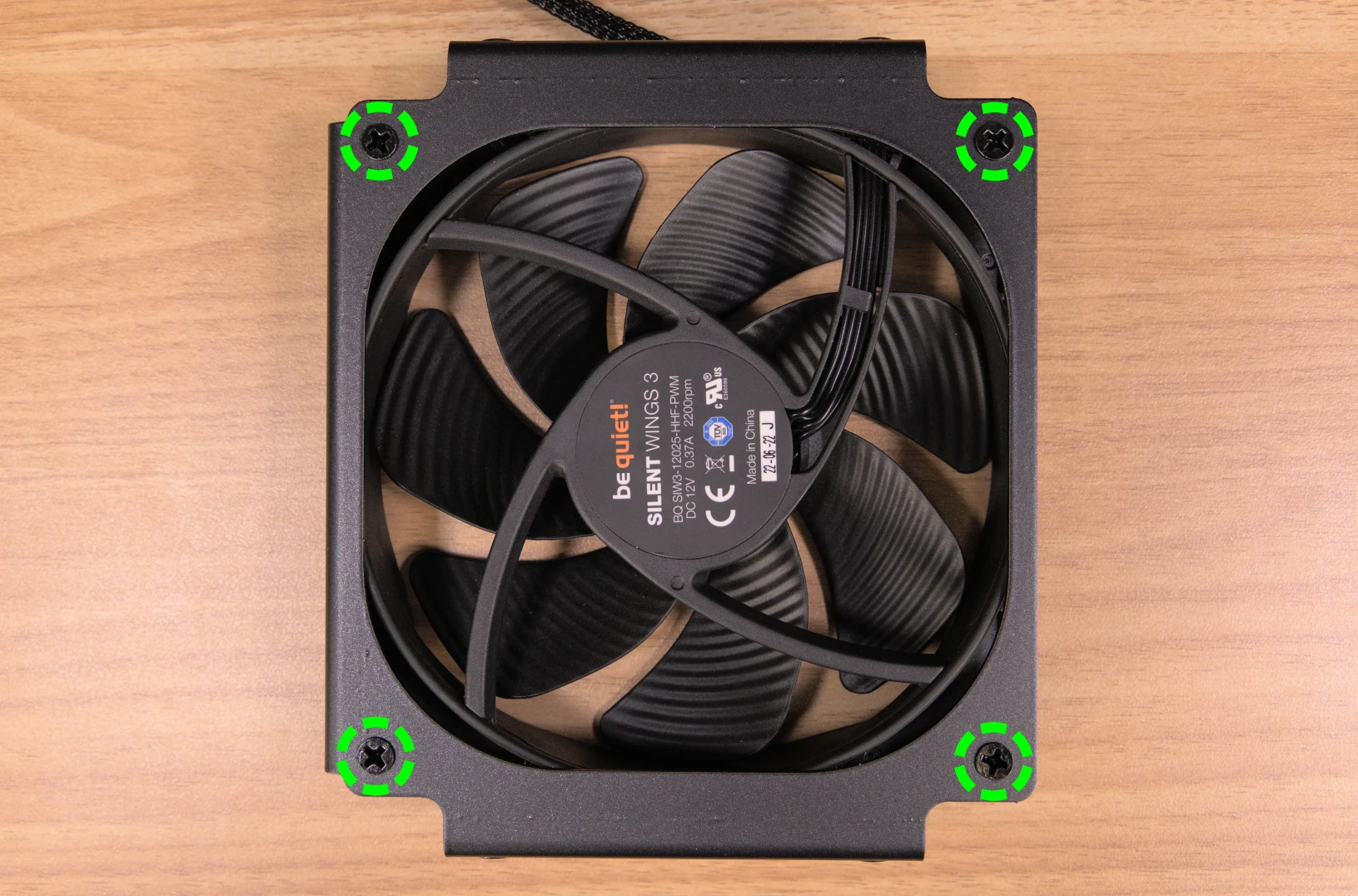
- When reinstalling the fan into the CPU duct, the spinning side should face inward (towards the front of the chassis), and the cable should point towards the closed corner of the top side of the duct (the top-right corner, when viewed from the back.)
- Overtightening the fan bracket’s screws may cause fan noise; if the fan is creating excessive noise, try slightly loosening some of the screws.
Steps to replace the cooler-mounted CPU fan:
- Follow the steps above to remove the top case, remove the GPU brace, and remove the CPU duct.
- Pull the corners of the fan’s top clip away from the heatsink it’s held to.
- Alternatively, the opposite side of the bracket (clipped onto the heatsink) can be released first.
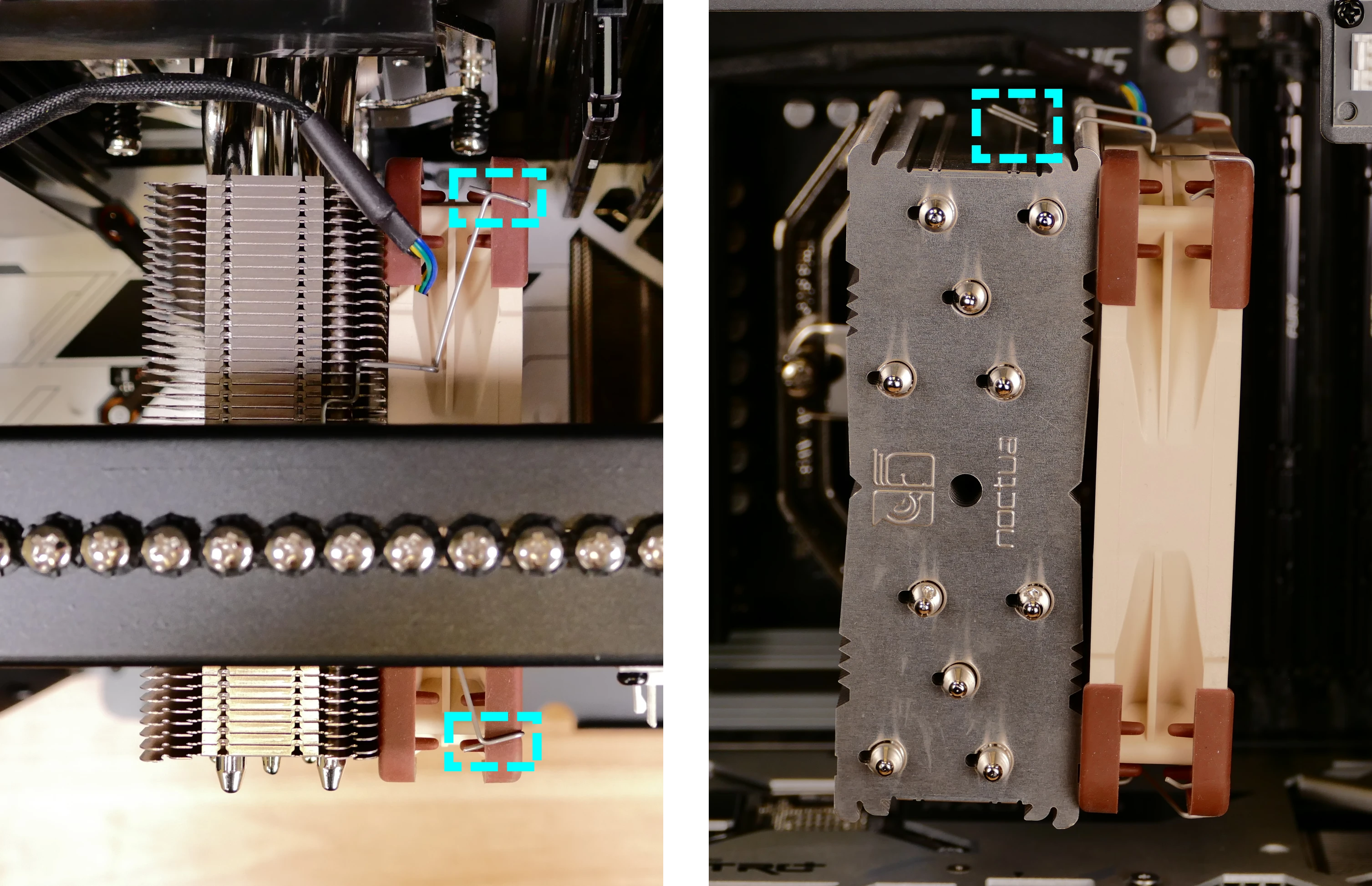
- Repeat the process for the bottom clip, then pull the fan and clips away from the CPU cooler.
- When reinstalling the CPU cooler fan, the side with a stationary cover should face the cooler, while the spinning side should face the front of the chassis.
- The cable should point towards the top inner corner (top-left when viewed from the back of the case.)
Replacing the CPU cooler and CPU:
The CPU cooler dissipates heat from the CPU to the heatsink, where the CPU fans expel it from the system. Depending on your climate and the age of the machine, replacing the thermal paste between the CPU and the cooler/heatsink may help the system run cooler.
The CPU uses an AMD AM5 socket. The CPU cooler is a Noctua NH-U12S.
Tools required: Cross-head (Phillips) screwdriver, thermal paste
Time estimate: 45 minutes
Difficulty: High ●
Steps to remove the CPU cooler/thermal paste:
- Follow the steps above to remove the top case, remove the GPU brace and GPU, remove the CPU duct, and remove the cooler-mounted CPU fan.
- While holding the CPU cooler in place so it doesn’t fall, unscrew the two screws holding the CPU cooler crossbar onto the vertical mounting brackets.
- The screws are held captive, and will not fully come out of the crossbar.
- Only the two outer screws need to be removed; the center screw holding the horizontal crossbar onto the heatsink does not need to be removed.
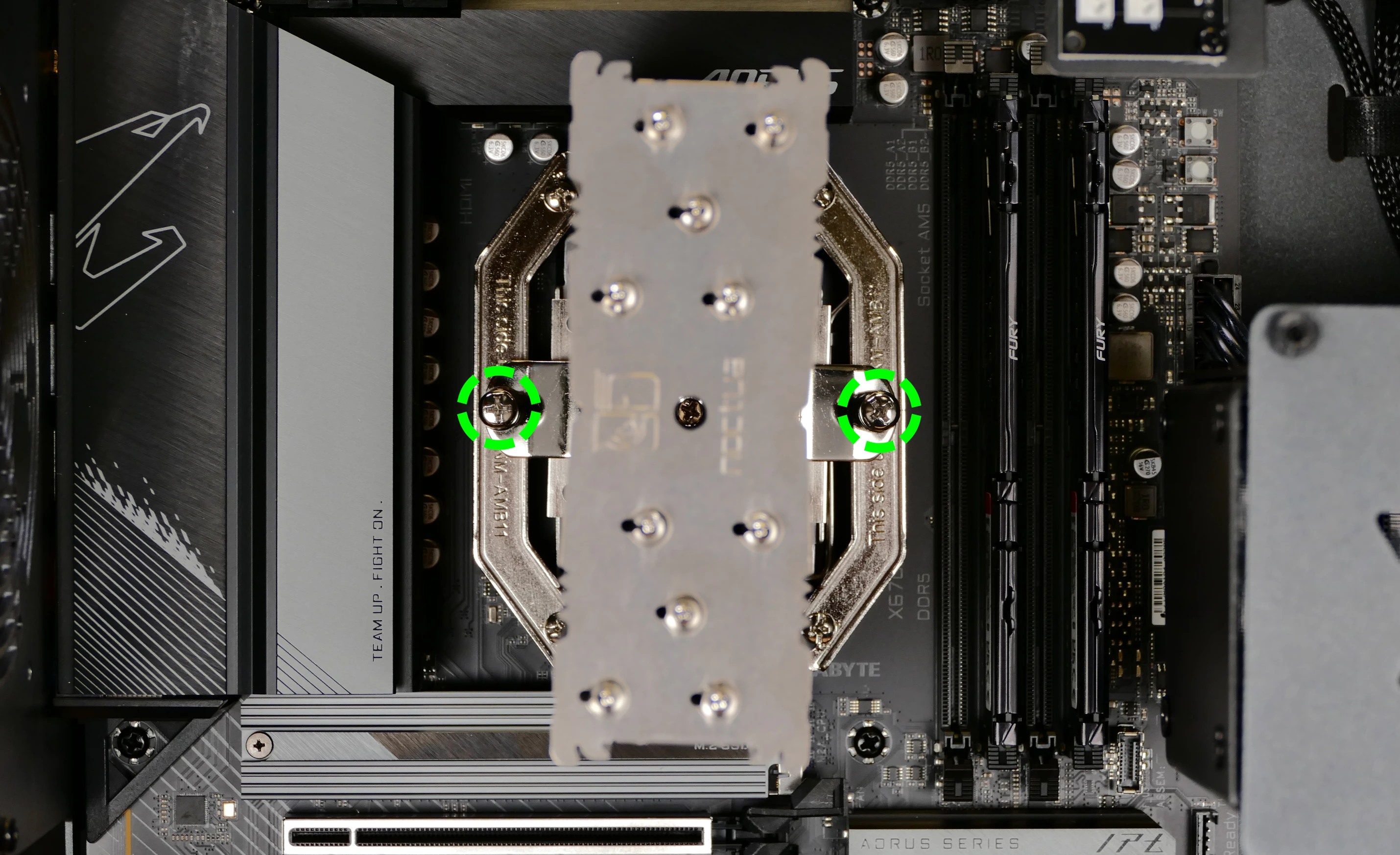
- The cooler will come away from the CPU.
- Using a paper towel, clean the existing thermal paste off of the heatsink and CPU. You may also use a small amount of rubbing alcohol if the old paste is dried or difficult to remove.
Steps to replace the CPU:
- Place the computer on its side so the motherboard is facing up.
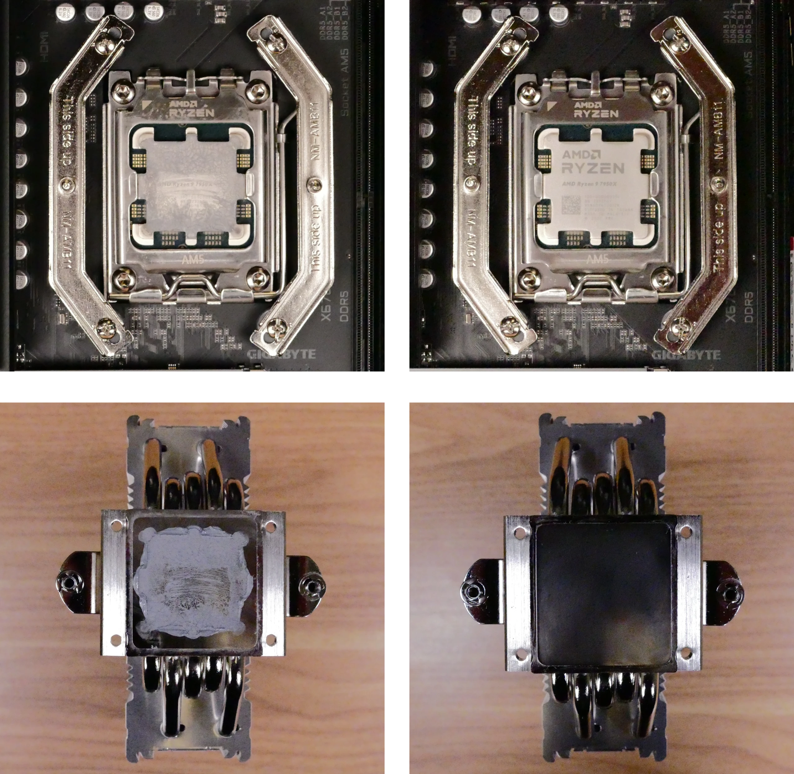
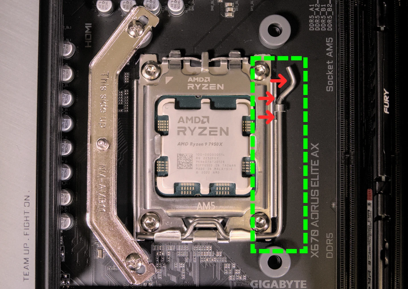
- Unscrew and remove the cooler mounting bracket on the right side of the CPU.
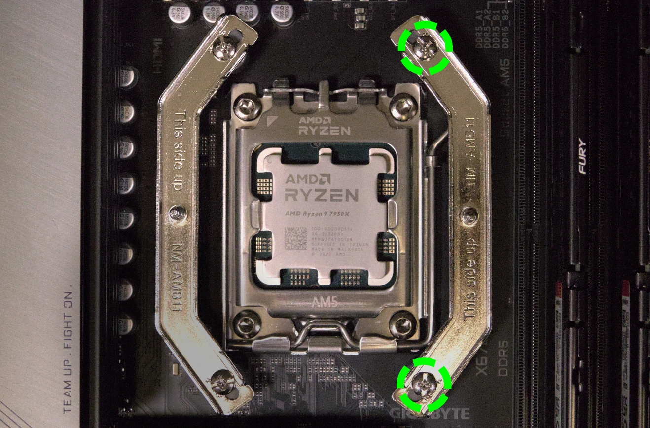
- Push the locking pin outward until it’s able to spring away from the motherboard.
- Caution: the locking pin may spring up with significant force when freed.
- Flip the CPU holder away from the CPU.
- The CPU holder opens in the opposite direction from the locking pin.
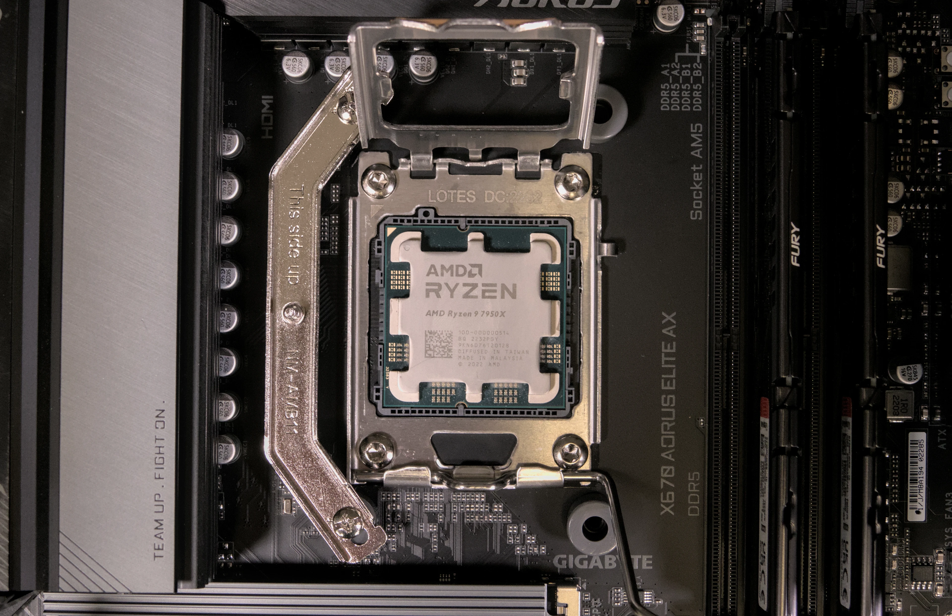
- Carefully lift the CPU out of the CPU socket.
- Be careful not to bend any of the gold pins on the CPU socket, and do not touch the gold pads on the CPU.
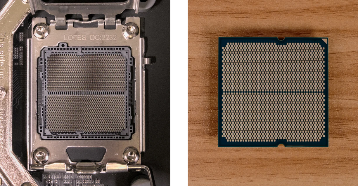
- Gently place the new CPU into the socket.
- The triangle on the CPU should be oriented to match the triangle on the CPU cover, pointing towards the top left of the motherboard.
- Flip the CPU cover back onto the CPU and push the locking pin down into place.
- Reinstall the right-side cooler mounting bracket.
Steps to install the thermal paste/CPU cooler:
- Draw an
Xshape of thermal paste onto the CPU.
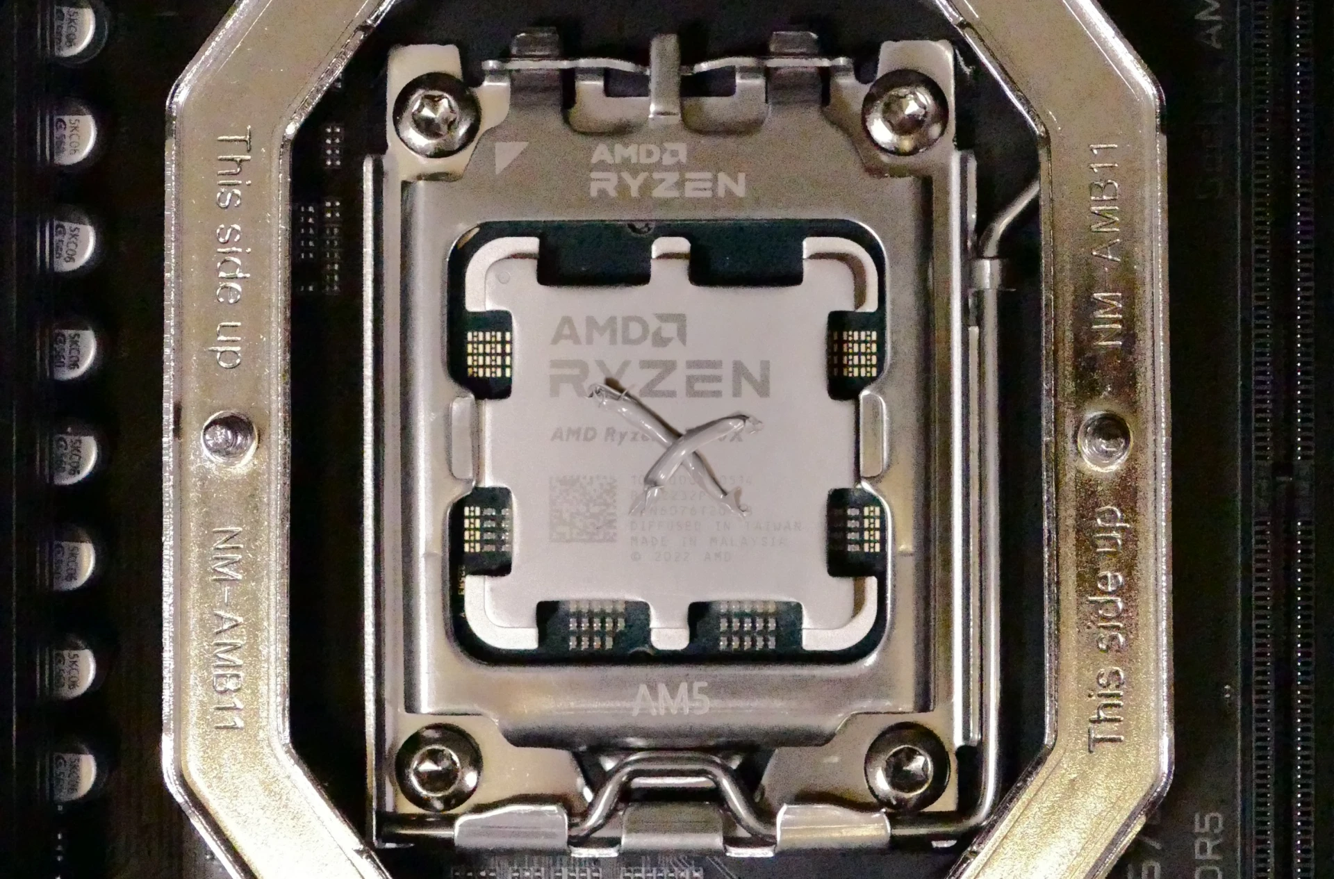
- Place the CPU cooler onto the CPU; while holding it in place, screw each end of the cooler crossbar onto one of the mounting brackets.
- The cooler should be oriented so the text is readable from the right side (front of the case).
- Insert each screw partially first, then fully tighten both.
- Set the computer upright, then reinstall the cooler-mounted CPU fan, CPU duct, GPU, GPU bracket, and top case.
Replacing the power supply:
The power supply unit (PSU) is modular and can be replaced with another unit of the same model. Different models may not be compatible with the cabling pre-installed in the Thelio.
Tools required: Cross-head (Phillips) screwdriver
Time estimate: 20 minutes
Difficulty: Medium ●
Steps to replace the power supply:
- Follow the steps above to remove the top case and remove the GPU brace and bottom GPU.
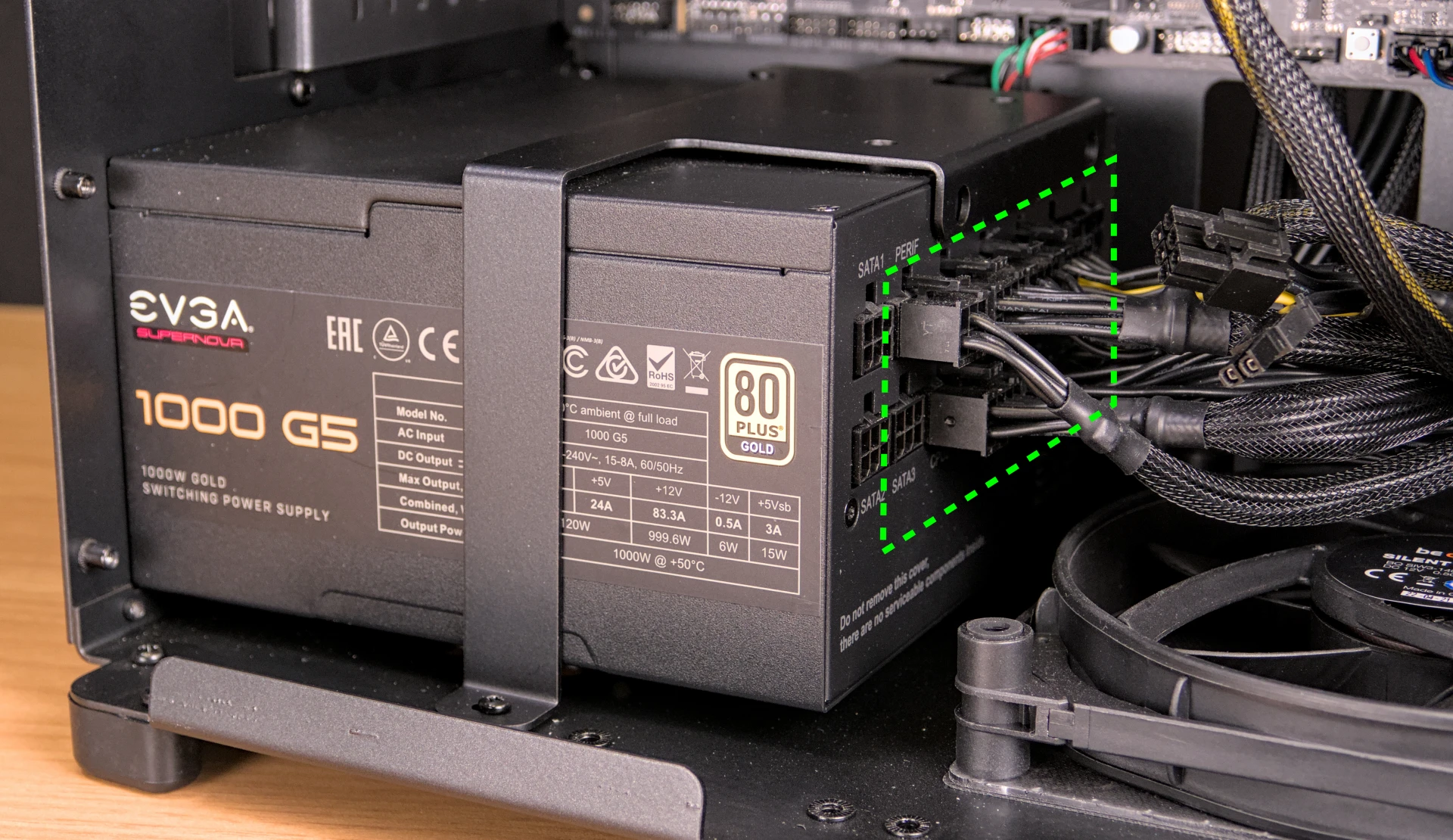
- Unplug all of the modular cabling from the back of the PSU.
- Some of the cables may be easier to unplug after the PSU has been unscrewed/removed from the case.
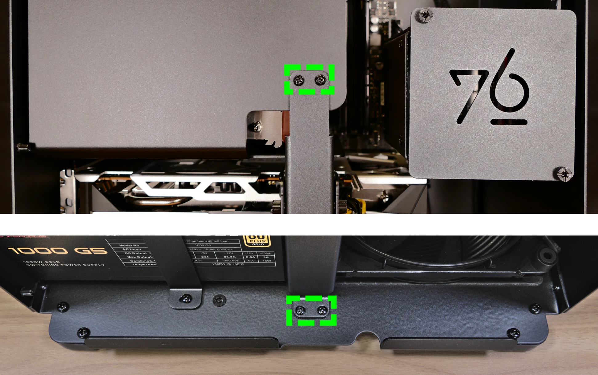
- Unscrew and remove the PSU bracket.
- One screw is located on the opposite side of the case.
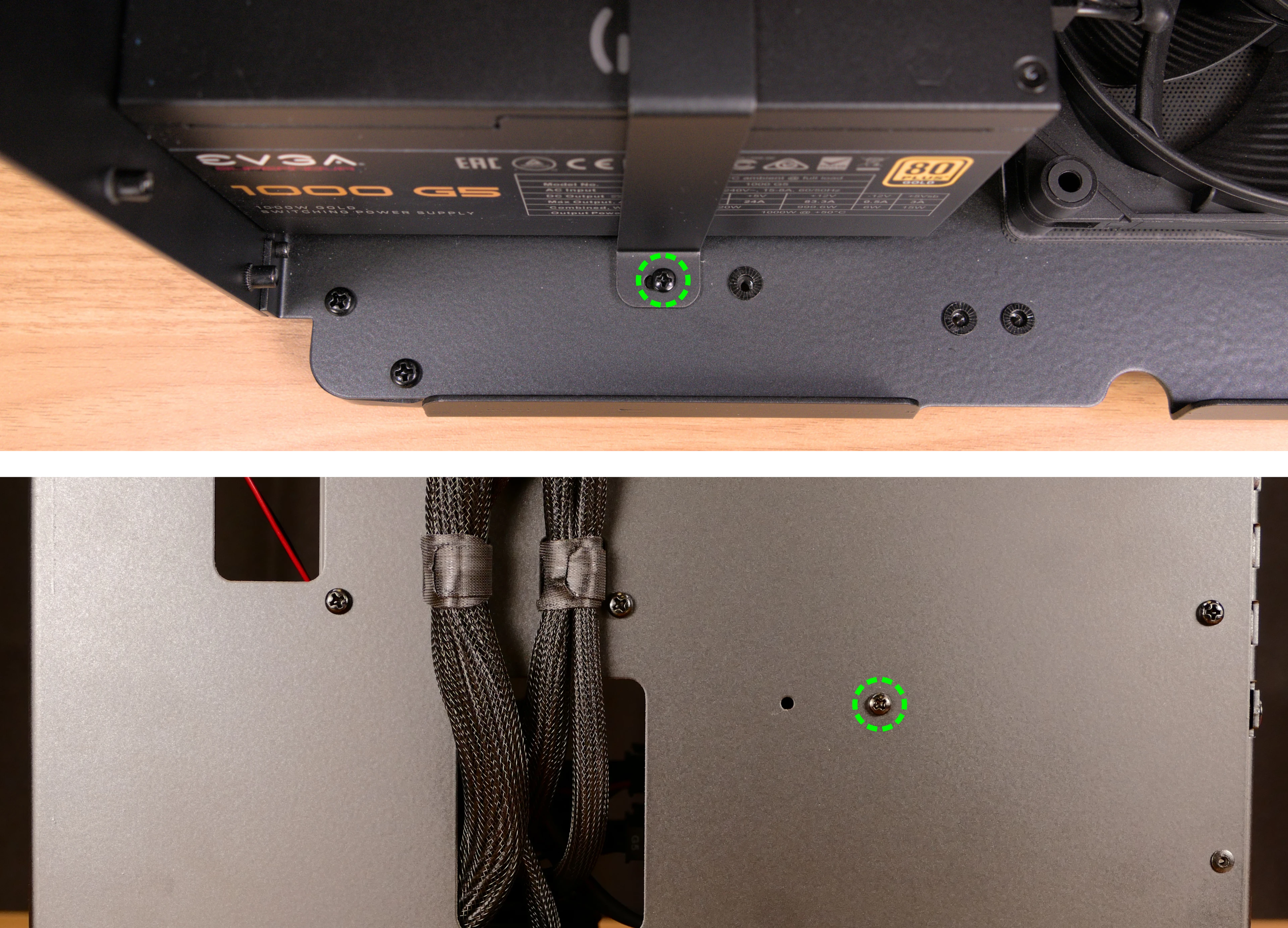
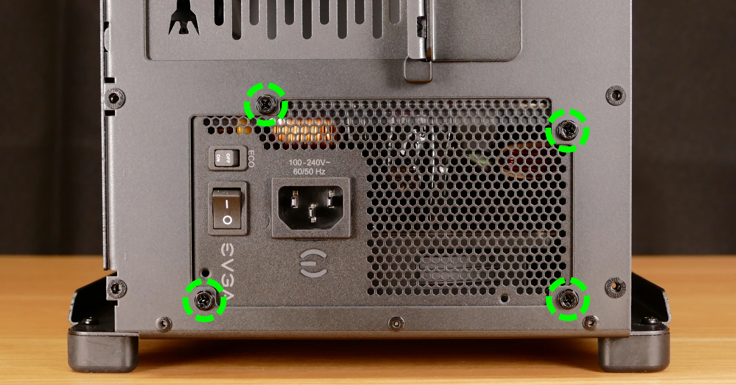
- Unscrew the four screws holding the PSU in from the back of the case.
- Remove/replace the PSU.
- Set the replacement PSU on top of the rubber post that holds it at the correct height.
- The replacement PSU should be installed with the fan facing the bottom of the case.
- After screwing in the replacement PSU, use the labels and pin counts on the cables and ports to ensure the power cables are reconnected in the proper locations.
- Remember that not all of the available connectors will plug into the PSU– two 8-pin (6 + 1) connectors are to be plugged into the GPUs.
- If the replacement PSU has an
ECOswitch, make sure it is switched on for an optimal fan curve.
Replacing the Thelio-IO board:
The Thelio-IO board handles the front power button, fan control, and 2.5“ SATA connectors for the system. If the Thelio-IO board becomes defective, it can be replaced using the instructions below.
Tools required: Cross-head (Phillips) screwdriver
Time estimate: 25 minutes
Difficulty: High ●
Steps to replace the Thelio-IO board:
- Follow the steps above to remove the top case and remove the 2.5“ drive cage cover and any 2.5“ drives that are installed.
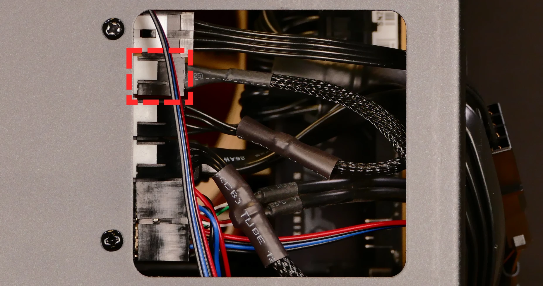
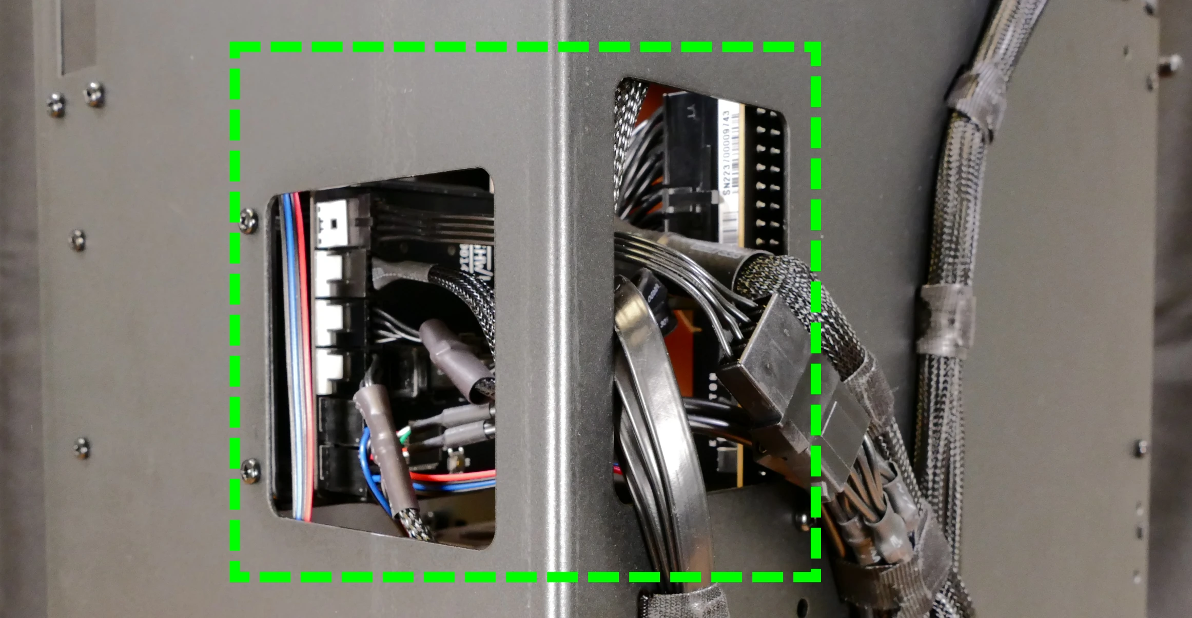
- Use the cutouts on the front right corner of the chassis to unplug all cabling from the Thelio-IO board.
- The topmost connector requires pulling the white tab while unplugging.
- Unscrew the two screws on the top side of the drive cage.
- While pulling the loose side of the drive cage away from the Thelio-IO board, move the board back and out of the drive cage.
- Place the new Thelio-IO board into the drive cage and replace the screws and wiring.
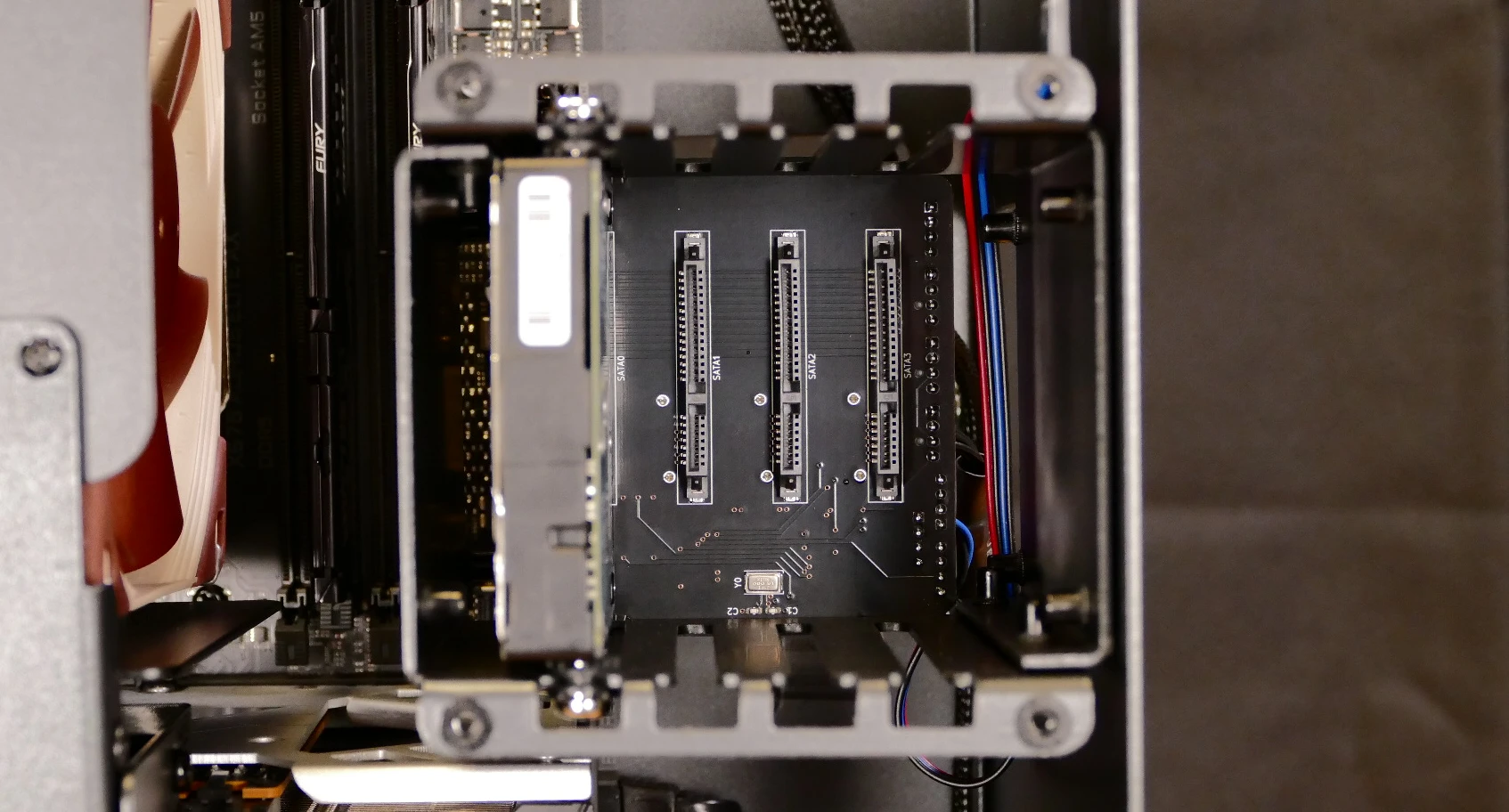
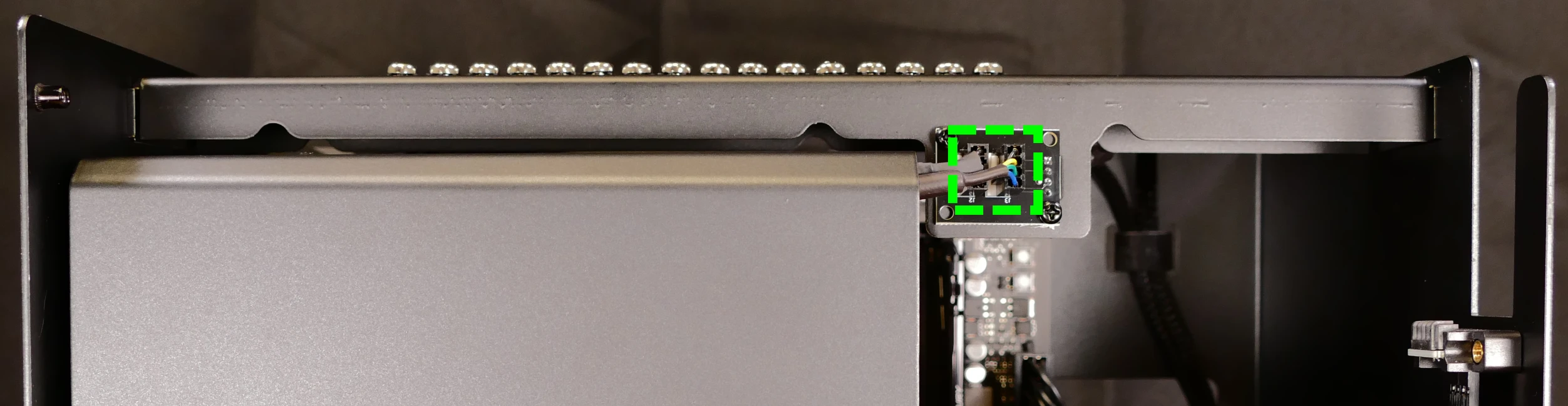
Thelio-IO wiring guide:
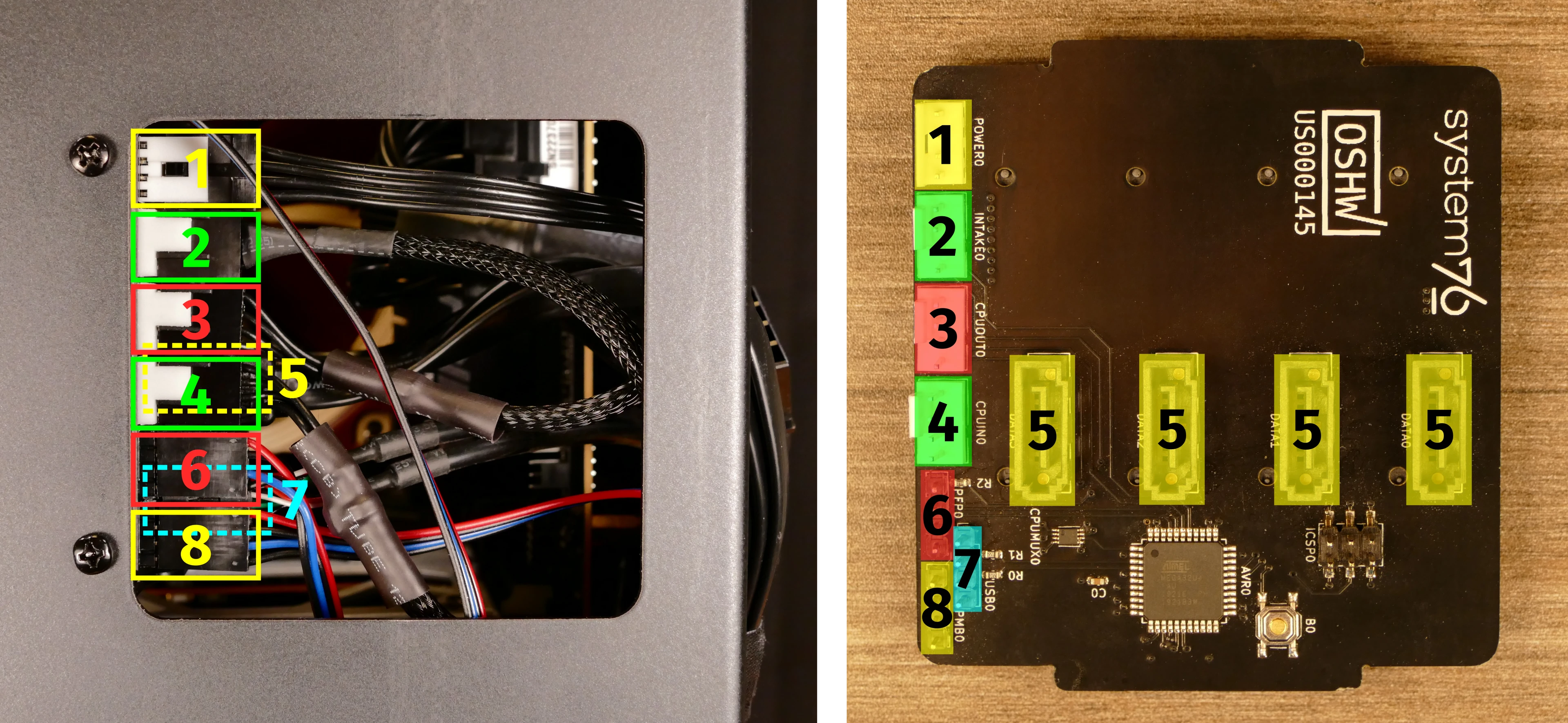
- When wiring the Thelio-IO board, refer to the above image and the following guide. The ports are numbered in the suggested connection order based on position and size.
- 1:
POWER0- to the power supplyPERIFport (via 4-pin Molex adapter.) - 2:
INTAKE0- to the bottom case fan. - 3:
CPUOUT0- to the splitter board (on the top crossbar) connecting to both CPU fans. - 4:
CPUIN0- to theCPU_FANheader at the top of the motherboard.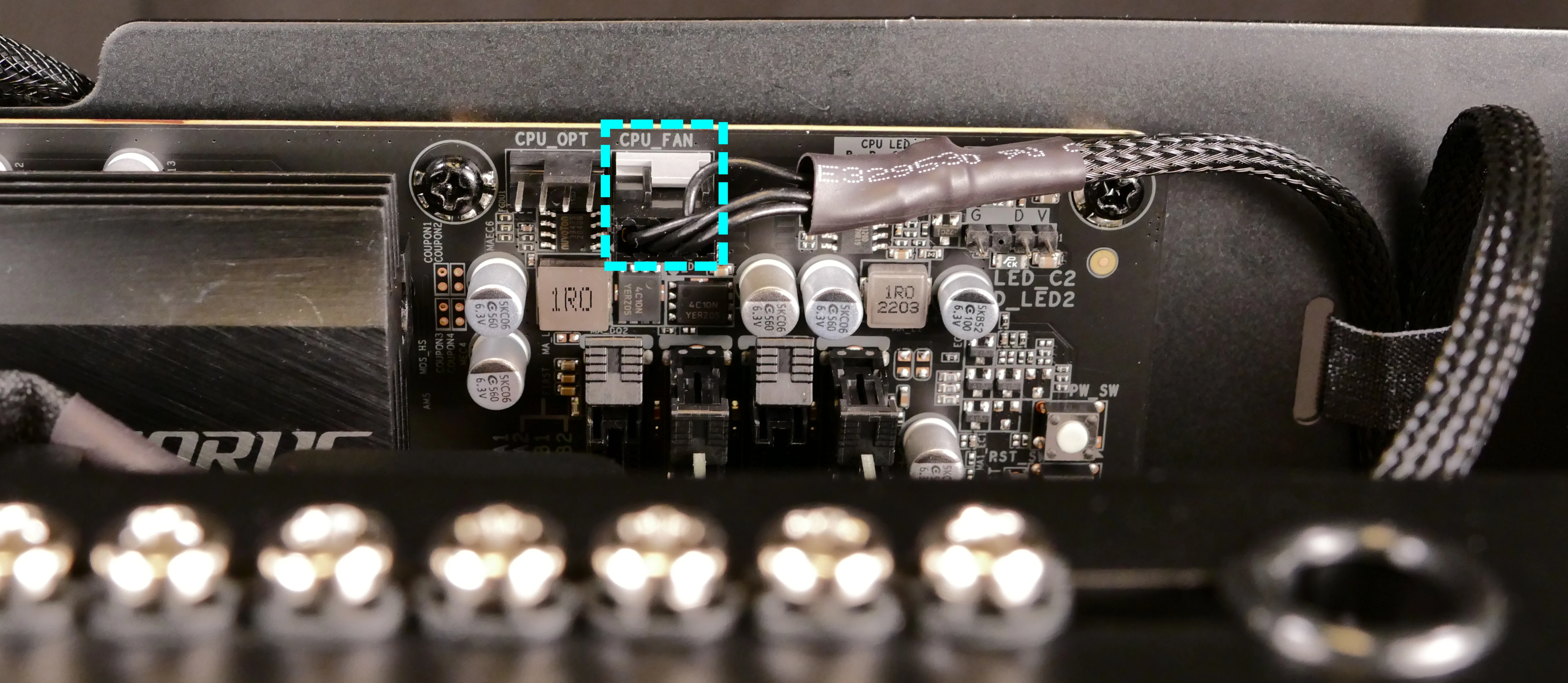
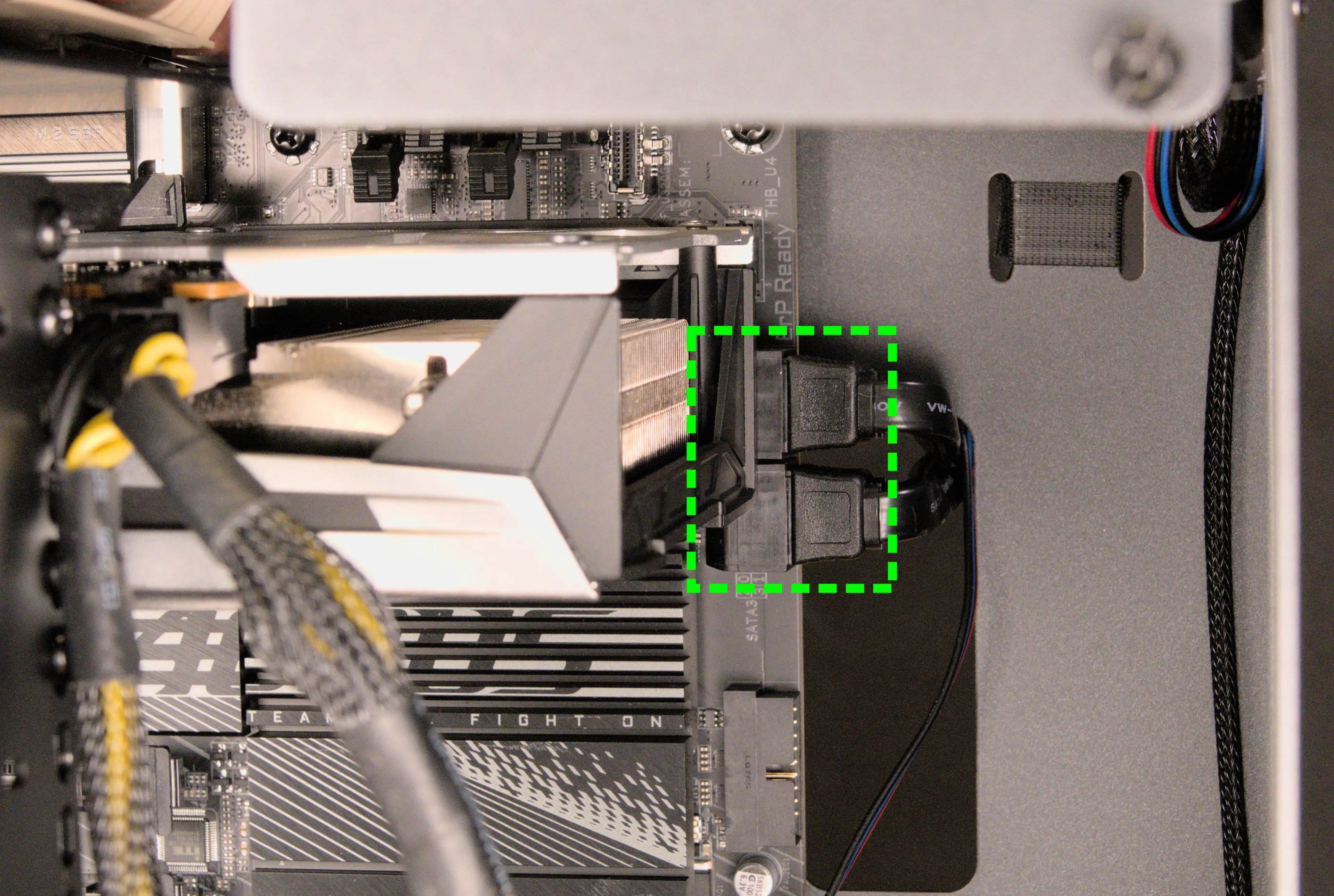
- 5:
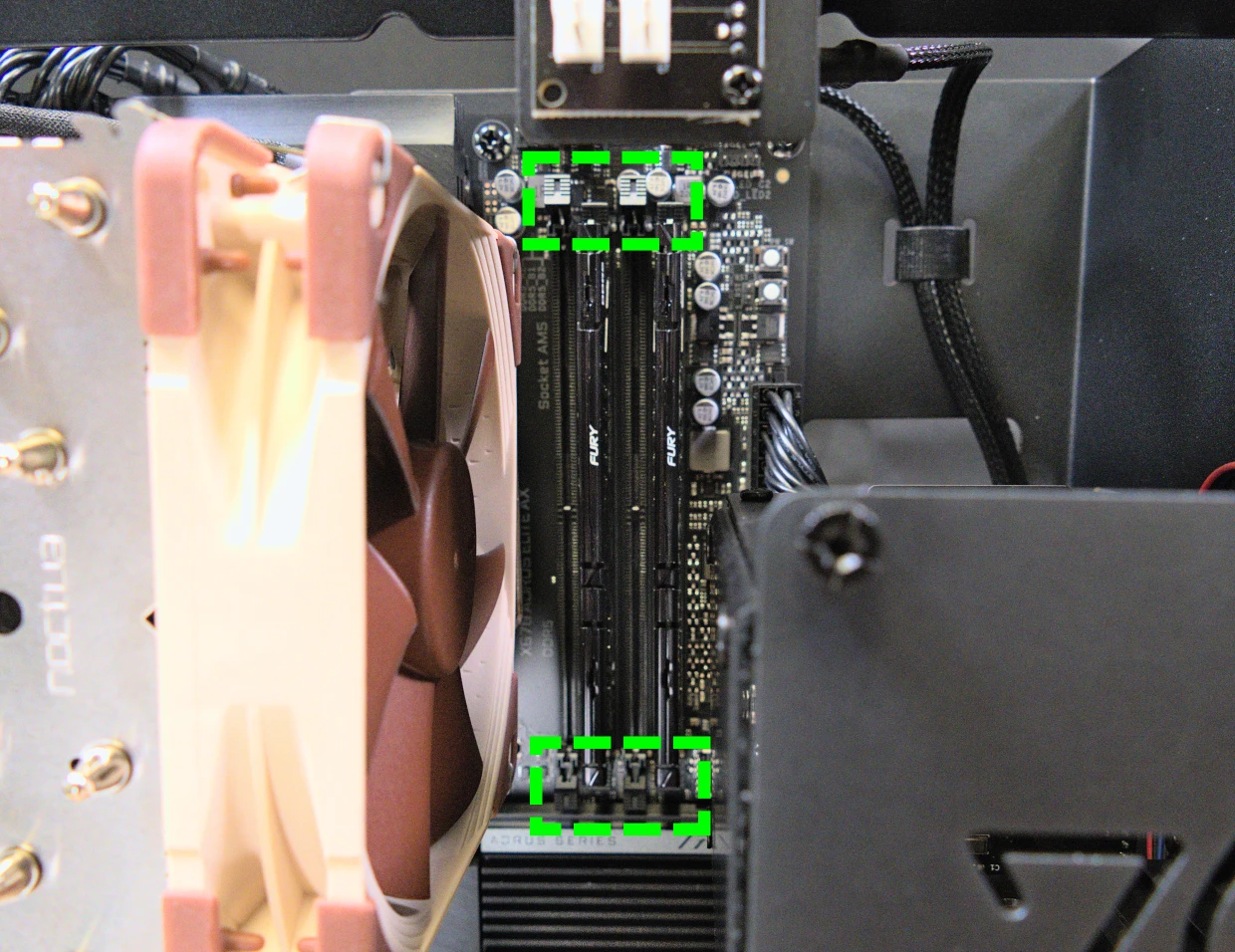
DATA0/1/2/3- to SATA ports #0/#1/#2/#3 on the motherboard, highlighted green below.- The ports are located next to the top GPU slot.
- These connectors provide data transfer for the 2.5“ drive slots.
- 6*:
PFP0- to the power button receptacle on the front panel. - 7*:
USB0- to theJUSB1header on motherboard, highlighted red below.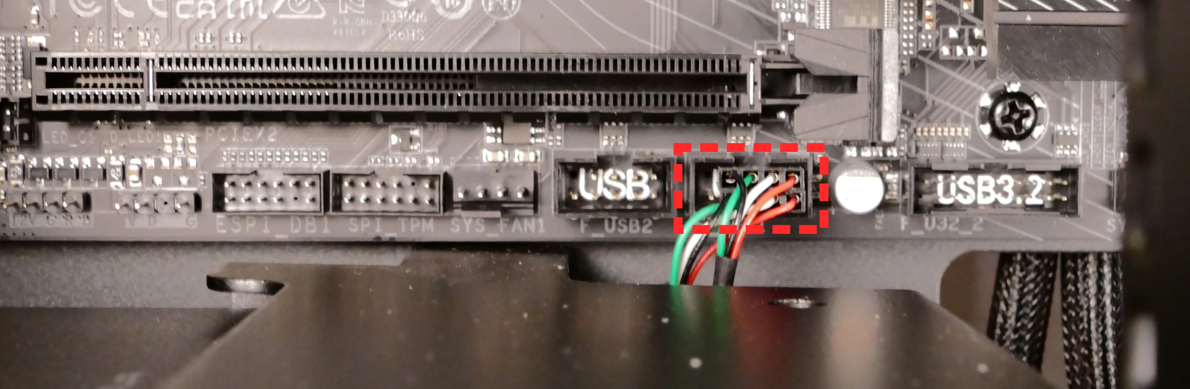
- On the Thelio-IO board, the row of four pins plugs in, while the row of five pins hangs off the back and does not plug in.
- This connector provides fan control and firmware updates.
- 8*:
PMB0- to the+PLED-and+PW-pins (the four top-left pins of theF_PANELheader) on the motherboard.- On the motherboard, the red wire goes on the inner-left and the black wire goes on the inner-right. The corresponding black wires go on the outer-left and outer-right.
- The
F_PANELheader is at the bottom right of the motherboard.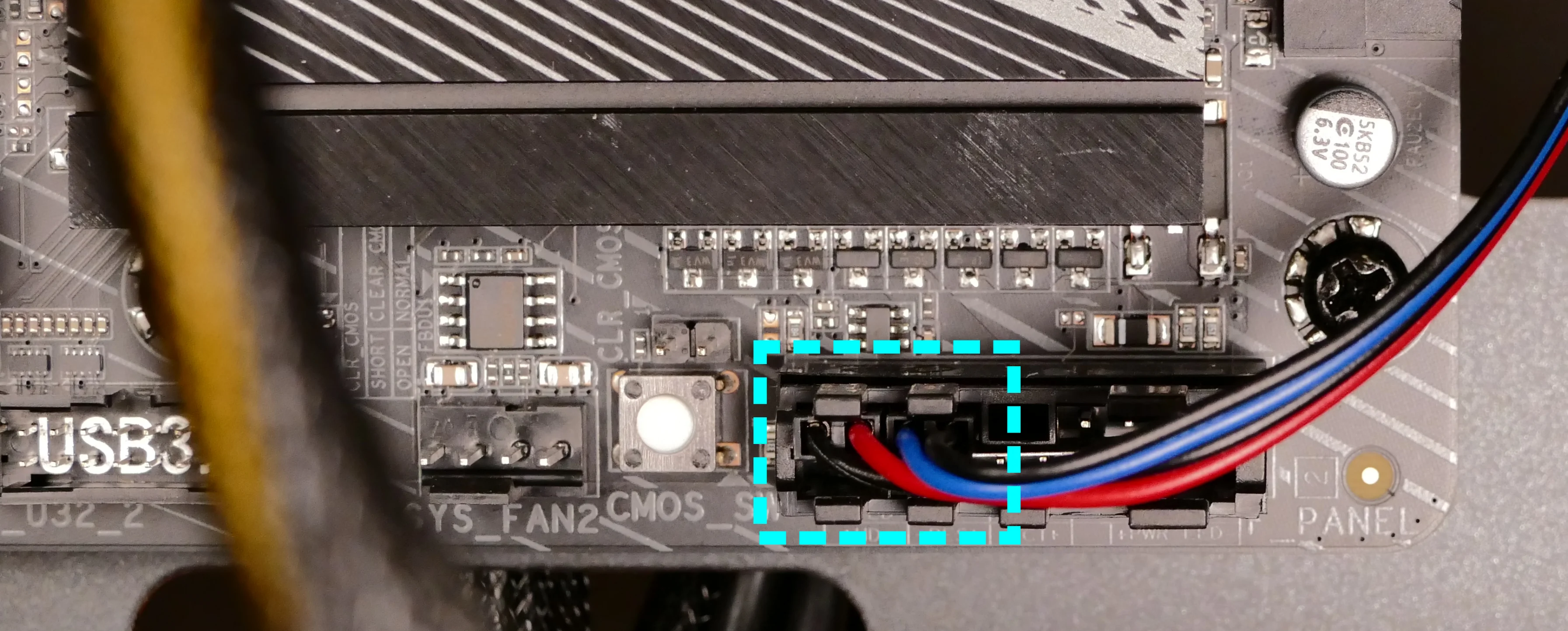
- * For all connectors with multi-colored wires plugging into the Thelio-IO board, the red wire goes on the top side (viewing from the front of the computer.)
- 1:
Troubleshooting the power button:
If the front power button doesn’t power the machine on or doesn’t light up when the system is powered on, try the following troubleshooting steps:
- Ensure the system powers on normally using the internal power button.
- Reseat the front power button to ensure it’s making proper contact.
- Check the wiring for the front power button.
- Replace the front power button, if necessary.
Tools required: Cross-head (Phillips) screwdriver (optional)
Time estimate: 20 minutes
Difficulty: Medium ●
Steps to power the machine on using the internal power button:
- Follow the steps above to remove the top case.
- Ensure the system is plugged into power, and the power supply switch is in the 1 (On) position.
- Push the small button labeled
B0on the Thelio-IO board.
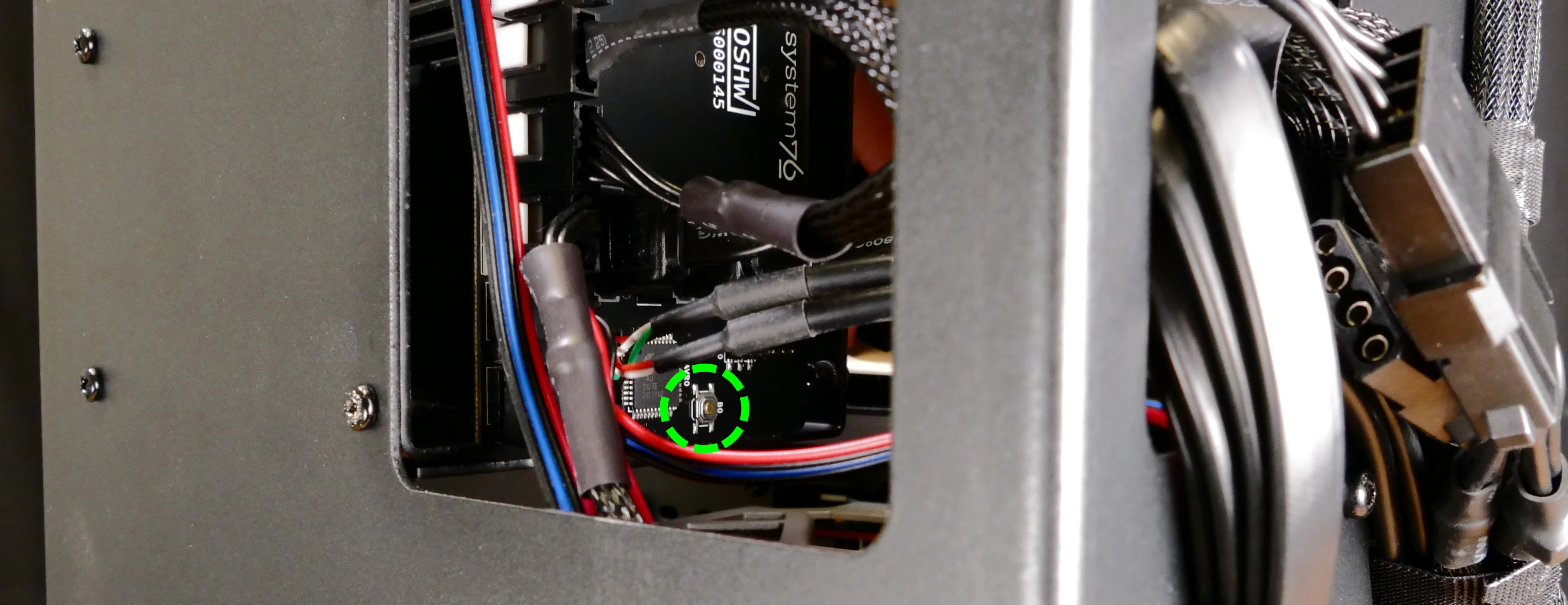
- If the Thelio-IO
B0button powers the machine on, then the issue is either the front power button or its connection to the Thelio-IO board. Check the front power button wiring. - If the Thelio-IO
B0button does not work, then the issue is either the Thelio-IO board or its connection to the motherboard. Check the wiring between the Thelio-IO board and the motherboard.
Steps to check the front power button wiring:
- Follow the steps above to remove the top case.
- On the back of the power button, the four pins should be connected to the four-wire connector as follows:
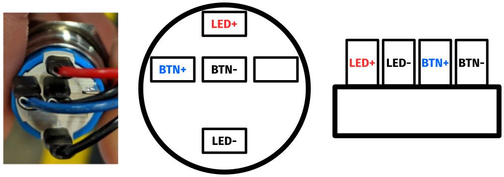
- On the front power button receptacle, the four-pin connector should have the red wire on the left and the black wire on the right (when viewed from the back of the computer.)
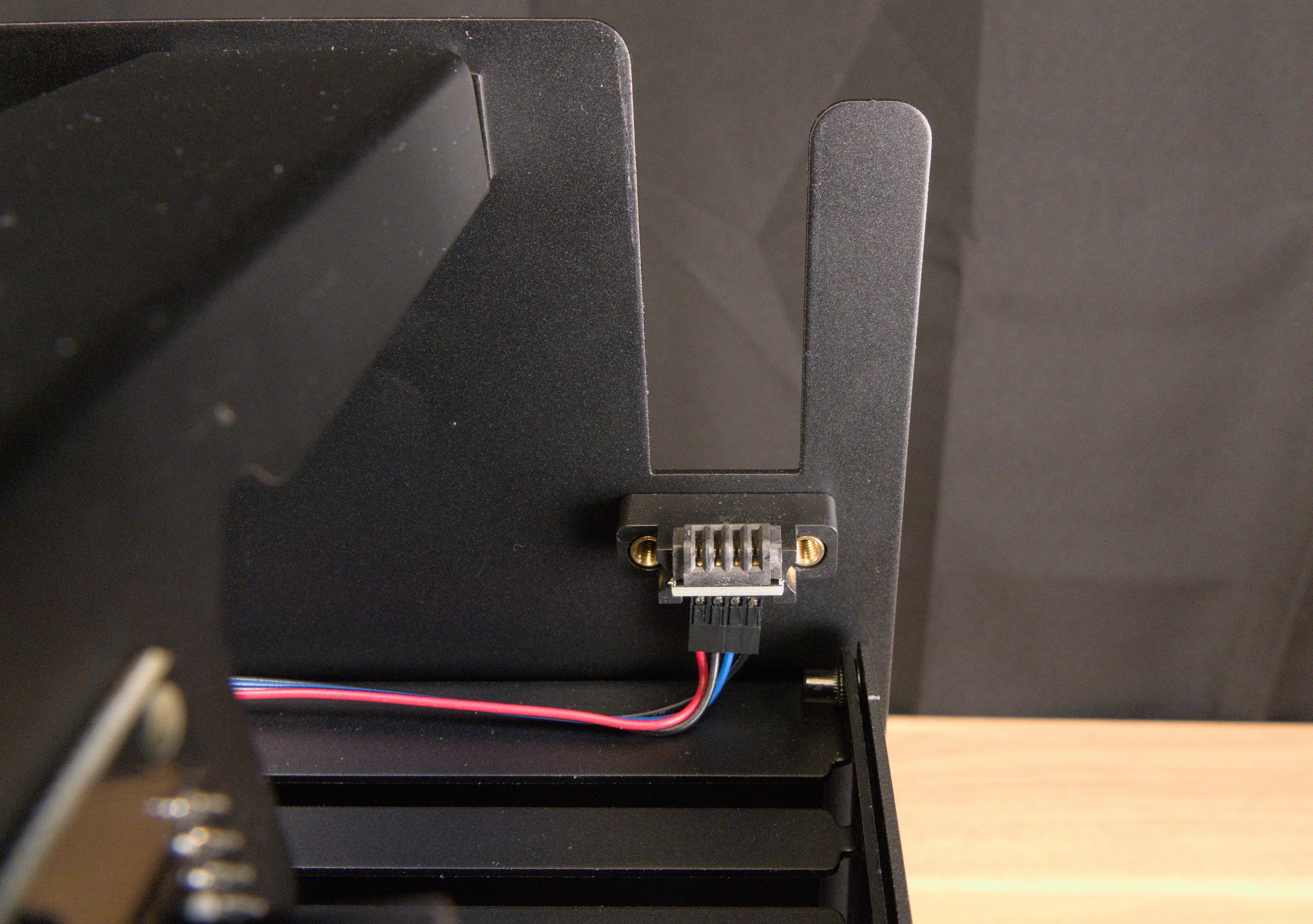
- The front power button receptacle should plug into the
PFPDport on the Thelio-IO board, with the red wire on the top (see the Thelio-IO wiring guide.)
Steps to replace the power button:
- Follow the steps above to remove the top case.
- Follow the instructions in the Replace the Thelio Power Button support article.