Darter Pro (Parts & Repairs)
Many components in your Darter Pro can be upgraded or replaced as necessary. Follow these step-by-step guides for instructions:
- Removing the bottom cover
- Replacing the RAM
- Replacing an M.2/NVMe SSD
- Replacing the WiFi/Bluetooth module
- Replacing the CMOS battery
- Replacing the fans/heatsink/thermal paste
- Replacing the keyboard
- Replacing the battery
Removing the bottom cover:
Removing the cover is required to access the internal components. Prior to removing the cover, ensure the AC power is unplugged and all peripherals (including SD cards and USB drives) are unplugged or removed from the system.
Tools required: Cross-head (Phillips) screwdriver
Time estimate: 7 minutes
Difficulty: Easy ●
Steps to remove the bottom cover:
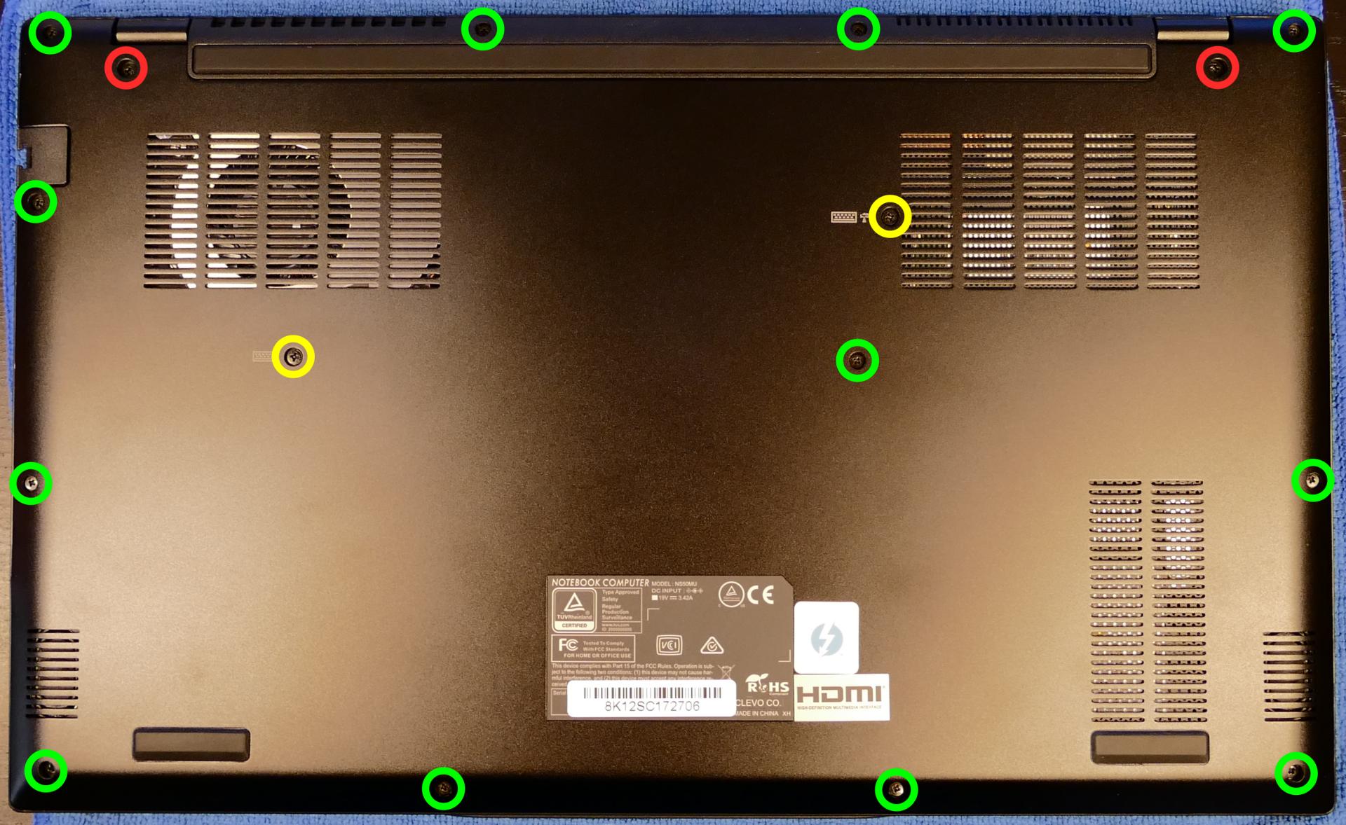
- Place the machine lid-side down.
- Use a soft surface (such as a towel) to avoid scratches.
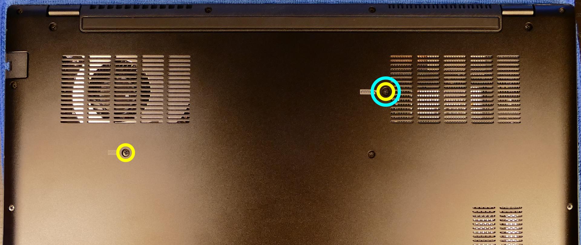
- Remove the 16 bottom panel screws:
- 12 perimeter screws (thin), highlighted green below.
- 2 keyboard screws (thicker), highlighted yellow.
- 2 inner hinge screws (thickest), highlighted red.
- Pull the bottom panel off, starting from the hinges in the back.
Replacing the RAM:
The Darter Pro 7 supports up to 64GB (2x32GB) of DDR4 SO-DIMMs running at 3200MHz. If you’ve purchased new RAM, need to replace your RAM, or are reseating your RAM, follow these steps.
Tools required: Cross-head (Phillips) screwdriver
Time estimate: 10 minutes
Difficulty: Easy ●
Steps to replace the RAM:
- Follow the steps above to remove the bottom cover.
- Press the small tabs on both sides of the RAM simultaneously. The RAM should spring up to an angle.
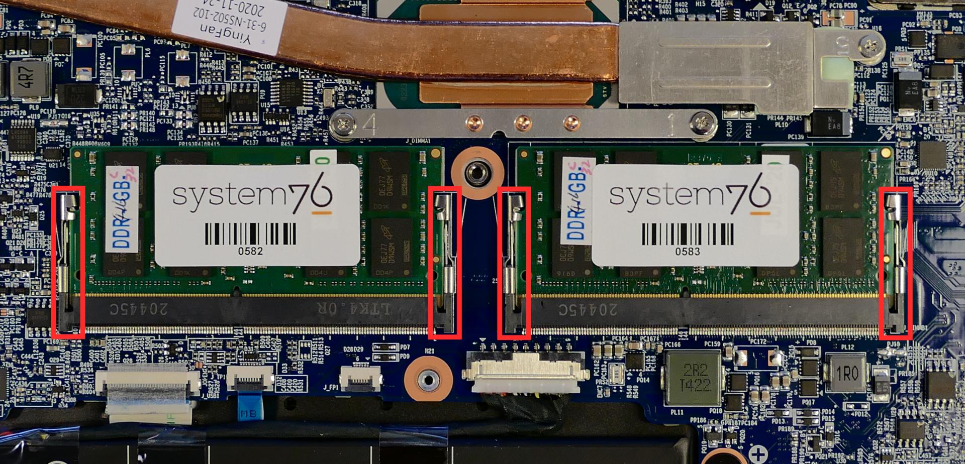
- Remove the RAM from the slot.
- Insert the new RAM (or reseat the existing RAM) by placing it in the keyed slot and pressing down until it clicks into place.
Replacing an M.2/NVMe SSD:
This model supports two M.2 SSDs. Both slots are size 2280. SSD-1 supports PCIe NVMe Gen 3 or SATA III, while SSD-2 supports PCIe NVMe Gen 4.
Tools required: Cross-head (Phillips) screwdriver
Time estimate: 10 minutes
Difficulty: Easy ●
Steps to replace the M.2 drive:
- Follow the steps above to remove the bottom cover.
- Unscrew the retainer screw opposite the M.2 slot.
- SSD-1 is closest to the battery (pictured on the left.)
- SSD-2 is closest to the outer edge of the machine (on the right.)
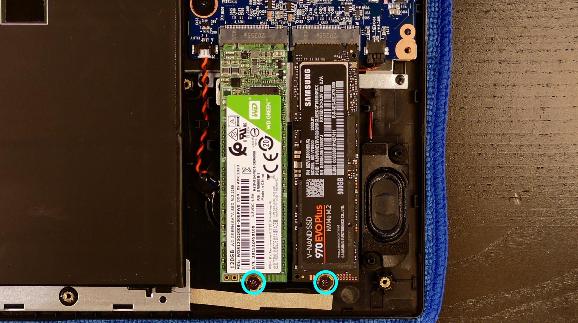
- Remove the existing M.2 drive by pulling it out of the slot.
- Insert the new M.2 drive into the slot and hold it in place.
- Replace the retainer screw.
- If a square brace was present on the old drive, transfer it to the new drive.
Replacing the wireless card:
Your Darter Pro’s WiFi and Bluetooth are both handled by the same module. It is a standard M.2 2230 slot with PCIe and USB interfaces (E-key).
Tools required: Cross-head (Phillips) screwdriver
Time estimate: 12 minutes
Difficulty: Medium ●
Steps to replace the WiFi/Bluetooth module:
- Follow the steps above to remove the bottom cover.
- Locate the wireless module. Remove any clear tape that is securing the wires.
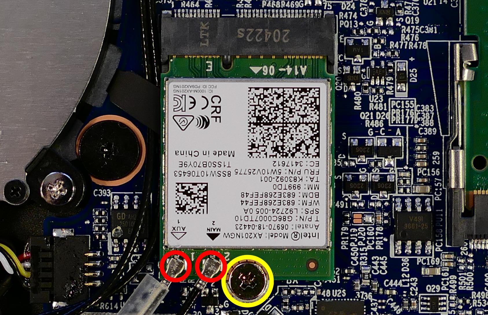
- Gently remove the two antennas (highlighted red above) by pulling them up and away from the wireless card.
- Remove the retaining screw opposite the M.2 slot, highlighted yellow above.
- The wireless card will pop up at an angle. Remove the card from the M.2 slot.
- Insert the new wireless card into the M.2 slot at an angle.
- Replace the retaining screw.
- Attach the two antennas by aligning the circular fittings and pressing onto the wireless card. The connectors will snap into place. Use caution when attaching the connectors; the pins can bend, break, or snap.
Replacing the CMOS battery:
The CMOS battery supplies power to the system’s CMOS chip. UEFI settings and the computer’s hardware clock are stored on the CMOS. If your system doesn’t boot, you can reset the CMOS to force a low-level hardware reset. If your clock is constantly resetting, it’s likely your CMOS battery needs to be replaced.
Warning (ingestion hazard): Keep batteries out of reach of children. Death or serious injury can occur if ingested. If a battery is suspected to be swallowed or inserted inside any part of the body, seek immediate medical attention. In the US, you can also call the National Battery Ingestion Hotline for guidance: 1 (800) 498-8666
Tools required: Cross-head (Phillips) screwdriver
Time estimate: 12 minutes
Difficulty: Easy ●
Steps to replace the CMOS battery:
- Follow the steps above to remove the bottom cover.
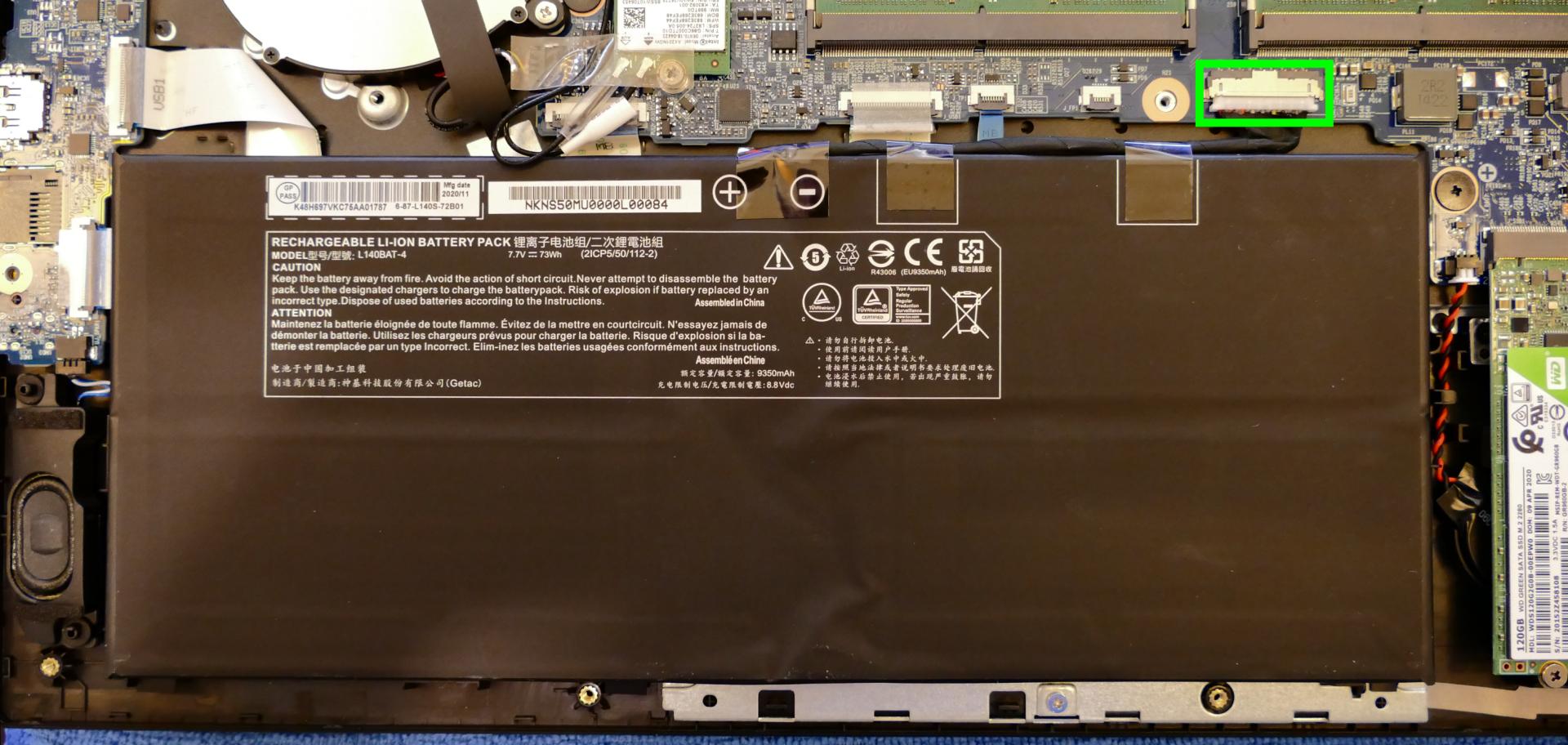
- Unplug the white connector attaching the CMOS battery to the motherboard (highlighted green below.)
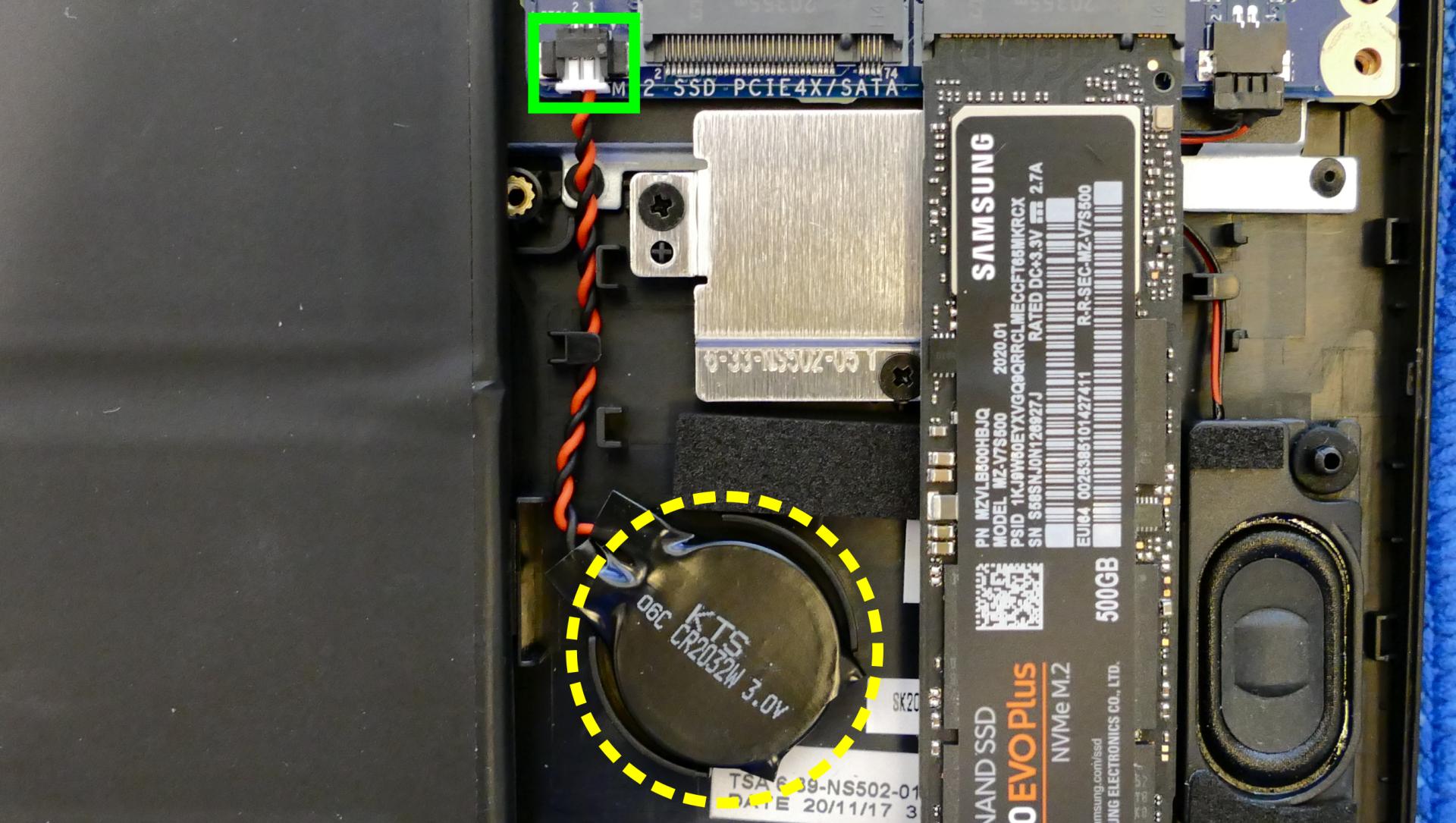
- If you are replacing the CMOS battery, remove SSD-1 to expose the CMOS battery, then pull it away from the adhesive holding it to the case.
- To clear the CMOS, disconnect the main battery, open the lid of the machine, and hold down the power button for at least 15 seconds to discharge any residual energy in the system.
- Re-connect the CMOS battery and the main battery, and replace the SSD and bottom panel.
- Power up the machine. The system may power itself off and on after initial boot; this is normal behavior when the CMOS has been reset.
Replacing the cooling system:
The Darter Pro 7 has a single fan and heatsink to cool the CPU. The fan and heatsink are a single part (they should not be replaced separately from one another.)
If the fan becomes noisy and cleaning it out doesn’t fix the issue, you may need a new fan. Contact Support to start a warranty claim or parts purchase.
Depending on your climate and the age of the machine, it may be necessary to apply new thermal paste between the CPU and the heatsink. Thermal paste helps facilitate effective heat transfer between the CPU and the cooling equipment. These instructions can also be used in the unlikely event your heatsink needs replacing.
Tools required: Cross-head (Phillips) screwdriver, thermal paste
Time estimate: 20 minutes
Difficulty: High ●
Steps to replace the fan/heatsink/thermal paste:
- Follow the steps above to remove the bottom cover.
- Peel back the black tape holding the fan to the chassis, and remove any clear tape that is securing the wires.
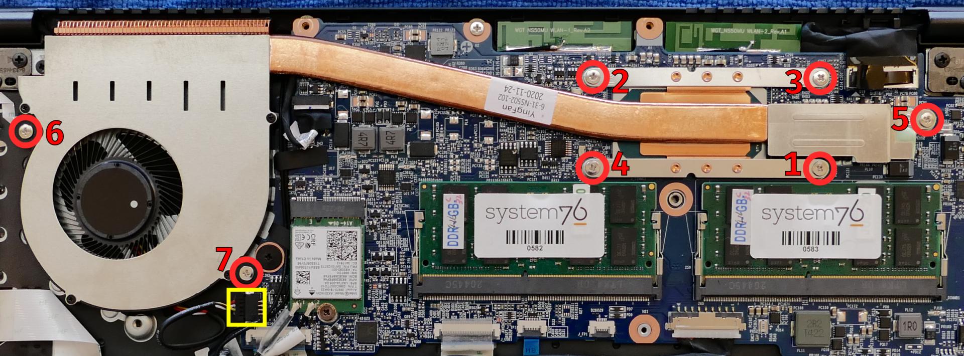
- Unplug the black fan connector.
- Remove the seven heatsink/fan screws in order, starting with #1, then #2, and so on until #7.
- Remove the fan and heatsink from the system, being careful not to bend the heatsink pipe. It may take some pressure to break the seal of the thermal paste.
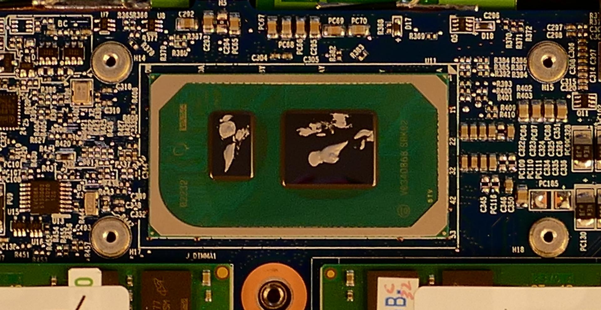
- Using a paper towel, remove the existing thermal paste. You may also use a small amount of rubbing alcohol if the old paste is dried or difficult to remove.
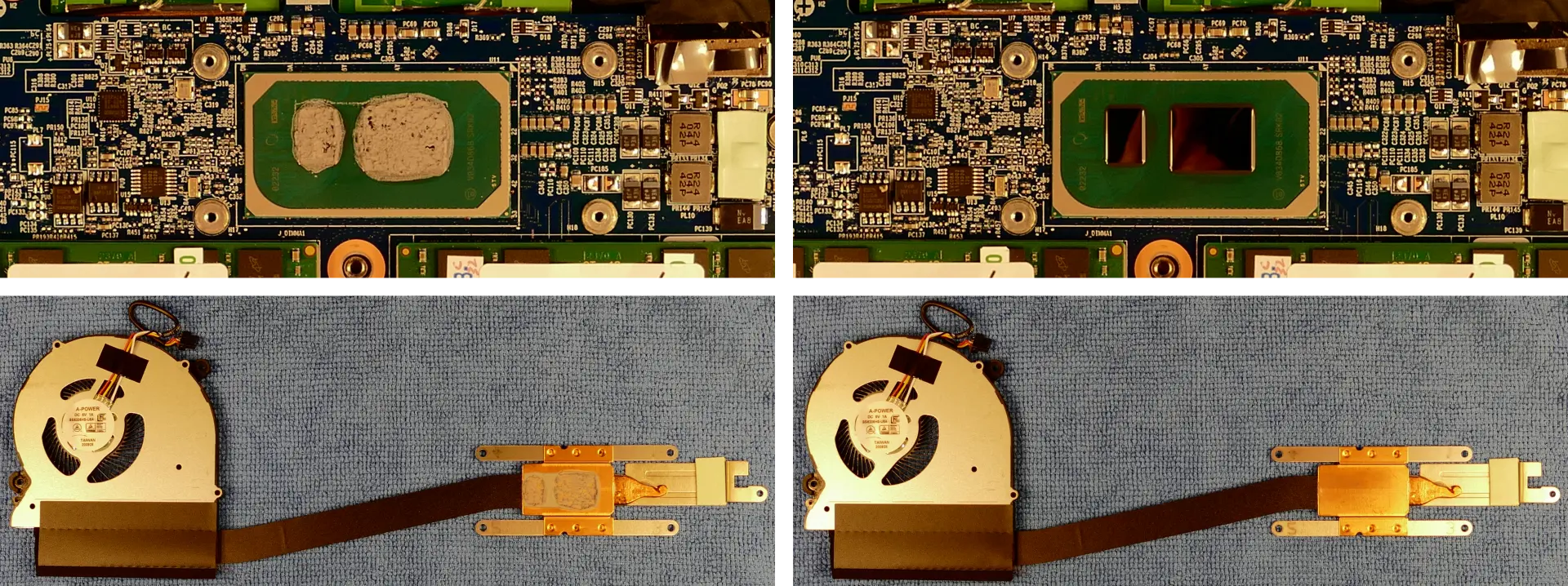
- After cleaning the CPU and heatsink, apply a small line of thermal paste directly onto the CPU chip.
- Carefully replace the heatsink.
- Replace the seven heatsink/fan screws in order, starting with #1, then #2, and so on until #7.
Replacing the keyboard:
The keyboard can be replaced using the instructions below.
Tools required: Cross-head (Phillips) screwdriver
Time estimate: 5 minutes
Difficulty: Easy ●
Steps to replace the keyboard:
- Place the machine lid-side down.
- Use a soft surface (such as a towel) to avoid scratches.
- Remove the two keyboard screws (highlighted yellow below).
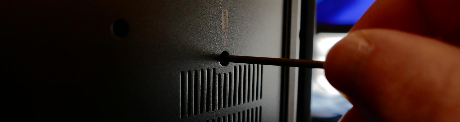
- Open the lid slightly and place the machine on its side.
- Push the screwdriver into the keyboard push point (highlighted cyan above) until the keyboard pops out.
- Set the machine back down and raise the keyboard away from the chassis. The larger ribbon cable is for the keyboard, while the smaller ribbon cable is for the keyboard backlight.
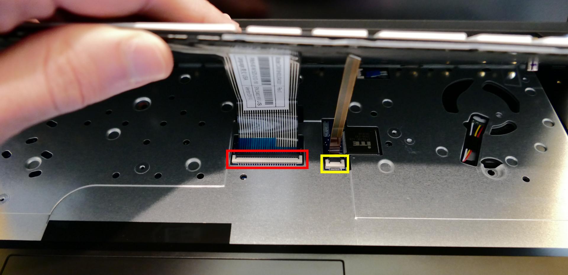
- Flip the black latches upwards to free the ribbon cables.
- Pull the ribbon cables out of the connectors.
- Remove the keyboard and replace it with the new one.
- Carefully slide both ribbon cables into their connectors.
- Flip the black latches back into place to secure the ribbon cables.
- Place the keyboard back into position, starting with the tabs on the bottom edge.
- Secure the rest of the keyboard by pressing down on each of its edges.
- Turn the machine lid-side down again and replace the two keyboard screws.
Replacing the battery:
The battery provides primary power whenever the system is unplugged.
CAUTION: Do not use metal tools to remove the battery. Do not touch the battery contacts with your hands or metal objects. If the battery is damaged during repairs, do not reinsert it into the laptop. Do not continue to use the computer if it contains a damaged battery. It is a potential fire hazard to operate a computer with a damaged battery. Keep children away from, and properly dispose of, the damaged battery. Always dispose of batteries carefully, by placing a piece of tape on the contact points. Take damaged batteries to an electronics recycling center and contact System76 to purchase a replacement. Batteries may explode or leak if exposed to fire, or if improperly handled or discarded. Only use batteries designed for your specific computer. This product contains a rechargeable battery. The battery is recyclable. At the end of its useful life, under various state and local laws, it may be illegal to dispose of this battery into the municipal waste stream. Check with your local solid waste officials for details in your area for recycling options or proper disposal.
The model number for the Darter Pro 7’s battery is L140BAT-4, and the original part number is 6-87-L140S-72B01. Third-party battery sellers may list one or both of these numbers, and may offer other compatible part numbers with the same model number. You can also contact System76 to purchase a replacement battery.
Tools required: Cross-head (Phillips) screwdriver
Time estimate: 20 minutes
Difficulty: High ●
Steps to replace the battery:
- Follow the steps above to remove the bottom cover.
- Unplug the white connector that connects the battery to the motherboard.
- Remove the battery.
- The battery is secured to foam standoffs with double-sided tape.
- A flat plastic object (such as a credit card) can be used to separate the tape from the battery.
- If any tabs from the tape are visible around the perimeter of the battery, hold them down while inserting the plastic tool so they don’t get pushed back under the battery.
- Put the battery back (or put your new battery in its place) and plug it back into the motherboard.